EP3819724B1 - Système agricole - Google Patents
Système agricole Download PDFInfo
- Publication number
- EP3819724B1 EP3819724B1 EP19208201.4A EP19208201A EP3819724B1 EP 3819724 B1 EP3819724 B1 EP 3819724B1 EP 19208201 A EP19208201 A EP 19208201A EP 3819724 B1 EP3819724 B1 EP 3819724B1
- Authority
- EP
- European Patent Office
- Prior art keywords
- clutch
- control
- power
- input shaft
- input
- Prior art date
- Legal status (The legal status is an assumption and is not a legal conclusion. Google has not performed a legal analysis and makes no representation as to the accuracy of the status listed.)
- Active
Links
Images

Classifications
-
- G—PHYSICS
- G05—CONTROLLING; REGULATING
- G05B—CONTROL OR REGULATING SYSTEMS IN GENERAL; FUNCTIONAL ELEMENTS OF SUCH SYSTEMS; MONITORING OR TESTING ARRANGEMENTS FOR SUCH SYSTEMS OR ELEMENTS
- G05B19/00—Program-control systems
- G05B19/02—Program-control systems electric
- G05B19/04—Program control other than numerical control, i.e. in sequence controllers or logic controllers
- G05B19/041—Function-oriented details
- G05B19/0415—Function-oriented details adapting phase duration according to measured parameters
-
- A—HUMAN NECESSITIES
- A01—AGRICULTURE; FORESTRY; ANIMAL HUSBANDRY; HUNTING; TRAPPING; FISHING
- A01F—PROCESSING OF HARVESTED PRODUCE; HAY OR STRAW PRESSES; DEVICES FOR STORING AGRICULTURAL OR HORTICULTURAL PRODUCE
- A01F15/00—Baling presses for straw, hay or the like
- A01F15/04—Plunger presses
- A01F15/042—Plungers
-
- A—HUMAN NECESSITIES
- A01—AGRICULTURE; FORESTRY; ANIMAL HUSBANDRY; HUNTING; TRAPPING; FISHING
- A01F—PROCESSING OF HARVESTED PRODUCE; HAY OR STRAW PRESSES; DEVICES FOR STORING AGRICULTURAL OR HORTICULTURAL PRODUCE
- A01F15/00—Baling presses for straw, hay or the like
- A01F15/08—Details
- A01F15/0841—Drives for balers
Definitions
- the invention relates to an agricultural system that includes agricultural baler machine, particularly but not exclusively, to a baler implement.
- Other aspects of the present invention relate to a method of controlling an agricultural baler.
- Baling machines are well known in agriculture and are widely used to bale plant matter in fields into bales that may be conveniently and effectively handled, stored and used. Baling machines are known that bale forage products such as grass and other leaves used as hay or other types of animal feed; straw or other plant parts resulting as by-products from a harvesting operation such as combine harvesting; cotton; and other plant parts of commercial or other value.
- baling machines in use in Europe are designed to be towed behind an agricultural tractor or another towing vehicle that, under the control of an operator and/or using operator-monitored software, moves the baling machine about a field and provides power to operate internal parts of the baling machine.
- the provision of power is effected by way of a rotatable power take-off (PTO) shaft connected to the rotary power take-off that typically is part of the tractor.
- PTO rotatable power take-off
- baler components are known in the part of the machine downstream of the pick-up.
- baling machine One commonplace type of baling machine is often referred to as a "rectangular baler”.
- This includes a cuboidal bale-forming chamber in which the ingested plant matter is compacted into a cuboidal shape by a piston or plunger that reciprocates longitudinally back and forth inside the bale-forming chamber between retracted and extended positions.
- Charges of plant matter repeatedly are fed into the bale-forming chamber from the pick-up by the mechanism of the baling machine. This action is timed with the motion of the plunger such that feeding of plant matter coincides with retraction of the plunger to one end of the bale-forming chamber.
- the plant matter then is compacted by subsequent extension strokes of the plunger along the bale-forming chamber.
- Such transverse-axis rotation is applied to a crank that is pivot-jointed to one end of a conrod the other end of which is pivot-jointed to the plunger, that is moveably captive inside the bale-forming chamber.
- rotation of the crank causes the reciprocal movement of the plunger.
- the flywheel and the plunger present a system having a high level of inertia and, in some cases, mechanical resistance (especially when the driveline is at rest or is moving slowly).
- the inertia and mechanical resistance can be increased by factors such as:
- the energy of the PTO shaft may be insufficient to cause either movement of the plunger or slipping of the baling machine driveline clutch, with the result that on engagement of the power take-off the engine of the tractor stalls. This may cause damage to the power take-off components or in some cases the engine of the tractor. Even if these outcomes do not occur, the inevitable interruptions in the baling activity are undesirable because of their adverse effect on bale quality and integrity and the wasting of commercially valuable plant matter.
- baling machine and "baler” are used synonymously herein and in the art generally.
- clutch except as otherwise explained embraces any design of clutch that is suitable for transferring drive in the circumstances described.
- plant matter potentially includes all types of matter that potentially may be ingested into a baling machine for the purpose of being formed into bales.
- bale and pluralnger in the context of the principal, moveable, bale-forming part of a bale-forming chamber are used synonymously herein.
- EP 3 398 427 A1 discloses an agricultural system comprises a baler with a plunger and a sensor for sensing a plunger-related value; a vehicle comprising a power source operable to convey power to said plunger; a CVT arranged to drive the plunger.
- an electronic control unit (ECU) is coupled to the sensor and to the CVT and is configured to receive the signal from the sensor; and cause said CVT to modify the gear ratio based on the signal from the sensor and on a mathematical model defining a CVT gear ratio variation profile derived from an expected load applied by the crop on the plunger.
- US 2014/0137757 A1 discloses a crop baler has a plunger reciprocable through compression and retraction strokes for compressing charges of crop material into bales within the baler.
- the crop baler also includes a rotatable flywheel operably coupled with the plunger for transferring kinetic energy to the plunger during reciprocation of the plunger.
- An output shaft is operably coupled with the flywheel for rotating the flywheel and driving the plunger through its compression and retraction strokes and an input shaft is adapted to be coupled with a power takeoff shaft of a towing tractor for receiving driving power from the tractor.
- the crop baler also includes a continuously variable transmission operably coupled between the input and output shafts for adjusting the ratio of the angular velocities of the shafts in response to changes in the angular velocity of the flywheel while maintaining the input shaft at a substantially constant angular velocity.
- WO2019/180040A1 relates to an agricultural baler comprising a flywheel and a drivetrain for coupling the flywheel to a connector that is arranged to be connected to a power take-off of a tractor, wherein the drivetrain includes a decoupling mechanism for decoupling the flywheel from the connector in case of an overload.
- EP3527064 (A1 ) relates to an agricultural baler for pressing cuboid bales, comprising a torque connection, a transmission shaft, a flywheel, a movement device, a compression element and a compression channel.
- the agricultural work vehicle may include one or more control devices, such as but not limited to programmable or non-programmable processors.
- the baler implement may include one or more control devices, such as but not limited to programmable or non-programmable processors. Additionally, or alternatively, the baler implement may be controlled by one or more control devices of the agricultural work vehicle. Similarly, the agricultural work vehicle may be controlled by one or more control devices of the baler implement.
- the agricultural work vehicle and/or the baler implement may be remote controlled, e.g. from a farm office. Accordingly, the agricultural work vehicle may include one or more communication interfaces for connection to a remote processor and/or a remote controller. Similarly, the baler implement may include one or more communication interfaces for connection to a remote processor and/or a remote controller.
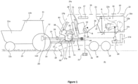
- baling machine 10 is shown being towed behind an agricultural work vehicle (towing vehicle) that in the illustrated embodiment non-limitingly is an agricultural tractor 11.
- the tractor 11 is a conventional tractor including a vehicle frame/body 11a, rearmounted cab 11b, front, steerable, ground-engaging wheels 11c and rear, driven, ground-engaging wheels 11d.
- Tractor 11 includes at its rear end between the rear wheels 11d a power take-off 12 of a conventional design that includes a rotative coupling for a PTO shaft 13 that extends rearwardly of the tractor 11.
- the PTO 12 may be engaged to cause rotation of the PTO shaft 13 or disengaged, such that the shaft 13 is not powered to rotate, for example through the operation of a control lever or pushbutton.
- the tractor 11 may have any of a range of engine power outputs including but not limited to 200 hp, 300 hp and 400 hp.
- the baling machine 10 is operable when towed by any such tractor 11, without a need for adjustment or modification, for the reasons explained below.
- the baling machine 10 i.e. a baling implement
- the baling machine 10 is secured to the rear of the tractor 11 by way of a drawbar 14 that typically is of an "A"-shape when viewed in plan and extends forwardly of the baling machine 10 below the PTO shaft 13.
- the drawbar 14 is pivotably secured to a conventional towing hitch at the rear of the tractor 11.
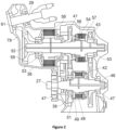
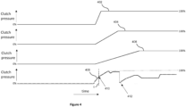
- the fourth plot 408 in Figure 4 shows a more sophisticated target-control-profile that can be used as the clutch-control-signal, wherein the clutch pressure level does not transition linearly from the low level to the high level. That is, the target-control-profile may have a nonlinearity. Also, the fourth plot 408 shows a clutch-control-signal for a clutch in a two-speed gearbox such as the gearbox that is described above with reference to Figure 2 .
- the rate of change of the clutch pressure changes from a first value (immediately before 't') to a second value (immediately after 't').
- This transition is labelled as 410 in Figure 4 , and represents a nonlinearity in the clutch-control-signal that is used to control the amount of torque transferred from the input shaft to the flywheel.
- the transition 410 occurs while the gearbox applies the same transmission ratio (that is, for the same gear in the gearbox). The specific details of the transition can be determined in a testing / configuration operation of the baler.
- the clutch-signal 408 of Figure 4 also shows that the clutch can be disengaged and then re-engaged to apply a second transmission ratio, as generally indicated with reference 412 in Figure 4 .
- the likelihood of engine stalling can be reduced or avoided by way of selecting an appropriate target-control-profile on the basis of the predefined-input-power-data received.
- the predefined-input-power-data may be indicative of the responsiveness of the engine driving the rotary input shaft, which may be provided by the operator or automatically retrieved by a control unit.
- the control unit may be able to accurately select an appropriate target-control-profile that will match the available power output of the engine and thus avoid inadvertent stalling.
- control unit determines and apply an appropriate target-control-profile as the clutch-control-signal for a high-powered tractor based on the received predefined-input-power-data.
- the control unit can perform similar processing for a mid- and low-power tractor.
- the control unit may set a maximum-pressure-value based on the power level of the tractor. The maximum-pressure-value can determine the end point of the pressure plots that are shown in the first to third plots in Figure 4 in particular.
- a high-power target-control-profile having a maximum-pressure-value of 19 bar for example, may be predetermined to be suitable for engine with an output power of 380 HP or more.
- a low-power target-control-profile having a maximum-pressure-value of 12 bar for example, may be predetermined to be suitable for engines with an output power between 270 HP and 319HP.
- a mid-power target-control-profile having a maximum-pressure-value of 15 bar for example, may be predetermined to be suitable for engines with an output power between 320 HP and 379 HP.
- Each of these power-related target-control-profiles will set the maximum-pressure-value of fluid pressure that will be applied to the clutch, such that it is suitable for the corresponding power rating of the tractor engine.
- Each of the target-control-profiles that are described with reference to Figure 4 can be considered as one of a plurality of predetermined target-control-profiles.
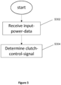
- Figure 5 shows a schematic flow chart of another method for controlling an agricultural baler according to an embodiment of the present disclosure.
- the method involves receiving input-power-data, which in this example is measured-input-power-data.
- the measured-input-power-data represents measurements of one or more operating parameters of the baler and / or the tractor (or more generally, of the agricultural system, which may or may not include the tractor).
- the measured-input-power-data may represent one or more of: the rotary input shaft speed, the PTO shaft speed, and/or the tractor engine output power.
- Each of these measures can indicate an ability of the tractor engine to meet the load requirements of the flywheel, especially during start-up when accelerating the flywheel up to its operating speed can require a lot of energy from the tractor engine.
- the method involves determining an error-factor.
- the error-factor can represent an indicator that one or more of the measurements has dropped below an expected value.
- the error-factor can include a binary flag that is set if a measurement drops below a threshold value, because this can be an indicator that the tractor engine is at risk of stalling.
- the error-factor can include an error-value that represents the difference between the measurement and a threshold value.
- the error-factor can include a binary flag that is set if a rate-of-change (optionally a negative rate-of-change) of the measurement exceeds a threshold value.
- the error-factor can include a derivative-value that represents the difference between the rate of change (derivative with respect to time) of the measurement and a threshold value.
- a derivative-value that represents the difference between the rate of change (derivative with respect to time) of the measurement and a threshold value.
- the method includes determining the clutch-control-signal based on the error-factor. As will be discussed below, this can involve determining a correction-factor for applying an offset to a current level of the clutch-control-signal to decrease the rate at which torque is transferred to the flywheel via the one or more clutches. This can either maintain a current clutch pressure (instead of increasing it) or can reduce the clutch pressure. This example enables the control unit to dynamically control the clutch such that the baler is started up (and the flywheel is brought up to speed) in a quick and efficient manner, with a reduced risk of the tractor engine stalling.
- control unit may not require operator input because it can start off with a clutch-control-signal that assumes that a highly-responsive tractor engine is available, and only reduce the speed with which the clutch is engaged (by reducing the slope of the clutch-control-signal) if the measured operating parameters indicate that the tractor engine is at risk of stalling.
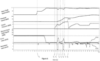
- the engine of the tractor is started at a time t 1 , which relates to around 11 seconds in Figure 4 .
- the tractor engine provides PTO shaft speeds, and therefore, baler input shaft speeds 602 of around 500rpm when the engine is first started, and no load is connected to the input shaft. It will be appreciated that this input shaft speed is dependent on the engine used and shall not be limiting to the scope of the present disclosure.
- the control unit will prompt the operator to increase the input shaft speed 602 (and hence the PTO shaft speed) to a level that is suitable for efficient operation of the baler.
- the target input shaft speed is 862rpm.
- the control unit may automatically increase the output speed of the tractor engine so as to increase the input shaft speed 602 without the operator being required to increase the speed manually. This automatic control of the tractor engine output speed may be in response to an operator providing input for initiating the baler start-up procedure.
- the control unit may monitor the input shaft speed 602 once it is up to speed, and before the clutch is engaged, to determine the value of the desired input shaft speed 608 that will be used during the clutch engagement operation. For example, if the input shaft speed has been successfully brought up to 862rpm, then this value will be used for the desired input shaft speed 608. If, however, it was only possible to bring the input shaft speed up to 850rpm, then this value will be used as the desired input shaft speed 608. This can enable any unexpected variance in the "normal" input shaft speed to be accommodated by the algorithm. Alternatively, a predetermined fixed value can be used as the desired input shaft speed 608.
- the input shaft speed 602 is an example of measured-input-power-data, and it is data that is indicative of whether or not sufficient drive power is available at the rotary input shaft.
- the control unit can process the input shaft speed 602 to determine the clutch-control signal (for setting the clutch-pressure 606). Furthermore, the control unit can determine one or both of (i) the error-value 610; and (ii) the derivative-value 612, based on the input shaft speed 602. The control unit can then determine the clutch-control signal based on one or both of (i) the error-value 610; and (ii) the derivative-value 612. Further details are provided below.
- the method is initiated at a time t 2 .
- the starting time t 2 may be automatically chosen by the control unit at a predetermined time after the input shaft speed 602 was brought up to its full operating speed (about 862rpm in this example), or once the input shaft speed 602 has remained above a set speed-threshold (such as 850rpm) for a predetermined period of time.
- the control unit applies a clutch-control-signal such that the clutch pressure 606 starts to increase with an initial slope / gradient.
- This initial-gradient may be a predetermined gradient, and may be a maximum-gradient in an attempt to start up the baler as quickly as possible.
- the maximum-gradient can correspond to a 7bar/s increase in the clutch-pressure 606.
- the control unit While the clutch is being engaged, the control unit is subtracting the input shaft speed 602 from the desired input shaft speed 608 in order to calculate the error-value 610. Also, the control unit is calculating the rate of change of the input shaft speed 602 in order to determine the derivative-value.
- control unit compares the error-value 610 with an error-value-threshold 614, and if the error-value 610 exceeds the error-value-threshold 614, then the control-unit determines a clutch-control-signal that has a reduced rate of change. This can be seen from Figure 4 after t 3 , where the clutch-pressure 606 initially flattens out from its initial-gradient and then has a negative gradient.
- control unit also compares the derivative-value 612 with a derivative-value-threshold 616, and if the derivative-value 612 falls below the derivative-value-threshold 616, then the control-unit determines a clutch-control-signal that has a reduced rate of change.
- the deceleration of the PTO shaft, as represented by the derivative-value 612, is directly proportional to the shortfall in the amount of power that is available for driving the flywheel.
- control unit can alter the clutch-control-signal (and hence the clutch-pressure 606) so as to reduce the amount of torque transferred from the input shaft to the flywheel.
- Figure 6 illustrates a sophisticated control algorithm in that it can take into account both the error-value 610 and the derivative-value 612 when determining the clutch-control-signal.
- Using the derivative-value 612 can advantageously enable any sharp changes in the input shaft speed 602 to be identified quickly such that remedial action can be taken by adjusting the slope of the clutch-control-signal.
- Using the error-value 610 can advantageously enable any slower changes in the input shaft speed 602 to be identified such that remedial action can be taken by adjusting the slope of the clutch-control-signal. Therefore, particularly good control can be achieved by determining the clutch-control-signal on the basis of both the error-value 610 and the derivative-value 612.
- control unit can determine the clutch-control-signal on the basis of only one of the error-value 610 and the derivative-value 612, or on the basis of the input shaft speed 602 directly (such as by comparing the input shaft speed 602 with a threshold).
- the control unit may determine the clutch-control-signal such that the clutch pressure 606 starts to increase with a predetermined slope / gradient.
- This gradient may be the initial-gradient, or a reduced-gradient (i.e. one that is less than the initial-gradient. It can be advantageous to apply a reduced-gradient on the assumption that the initial-gradient is unsustainable for the size of the tractor engine that is being used to power the baler.
- the reduction of the clutch pressure, and the reduction in torque transfer from the input shaft can be temporary, e.g. for as long as the error-value 610 remains above the error-value-threshold 614 and / or the derivative-value 612 remains below the derivative-value-threshold 616.
- the control unit may decrease the clutch-pressure 606 temporarily, shortly after the error-value has exceeded the error-value-threshold 614 and or the derivative-value 612 falls below the derivative-value-threshold 616.
- the decrease in clutch-pressure 606 can be temporary in order to enable the input shaft speed 602 (and hence also the tractor engine) to recover with a reduced load due to increased slip in the clutch. Once the input shaft speed 602 has recovered, the clutch-pressure can potentially start to be increased at a faster rate again without stalling the tractor engine.
- the amount of reduction in clutch-pressure 606, and therefore the amount of decrease in torque transferred to the flywheel may be based on the error-value.
- the control unit may reduce the clutch-pressure 606 by an amount that depends on the size of the error-value 610.
- a correction-factor (which represents a decrease in the amount of torque transferred to the flywheel) may be related to (optionally directly proportional to) the error-value 610.
- the control unit may set the correction-factor for the clutch-pressure 606 based on the size of the derivative-value 612.
- the control unit again reacts by decreasing the slope of the clutch-pressure 606 in order to delay full engagement of the one or more clutches and thereby provide more time for the tractor engine to reach its optimal working condition. Similar to the above, the slope of the clutch-pressure 606 may be reduced until a time t 7 , at which point the error-value 610 has dropped below the error-value-threshold 614.
- the control unit may determine the clutch-control-signal such that the clutch pressure 606 starts to increase with a predetermined slope / gradient. This gradient may be the same as an earlier used gradient, or may be a further-reduced-gradient (i.e. one that is less than the reduced-gradient).
- the clutch-control-signal that controls the clutch-pressure 606 as shown in Figure 6 may be applied by the control unit during start-up of the agricultural baler, e.g. when the transmission is set to its first selectable transmission ratio G1 by means of the first clutch 49. Once the first clutch 49 is fully engaged, a gear-change may be initiated at time t 8 , at which point the clutch-pressure 606 of the first clutch 49 is significantly reduced to disengage the first clutch 49 and select the second transmission ratio G2 by gradually pressurising the second clutch 54.
- the embodiment described above includes the use of a dynamically defined clutch-control-signal based on measured-input-power-data (the input shaft speed 602).
- the available power output of the engine was too low for the initial-gradient, such that the gradient of the clutch-pressure profile 606 was reduced to avoid stalling.
- the control unit may be configured to store a transcript of the clutch-control-signal (that results in the clutch-pressure 606 shown in Figure 6 ) as prior-clutch-control-data for future use.
- the prior-clutch-control-data may be used directly as a new target-control-profile for future baler start-up procedures (such as the ones shown in Figure 4 ).
- the control unit may prompt the user to enter predefined-input-power-data indicative of the responsiveness of the tractor engine that is driving the rotary input shaft.
- the control unit may be configured to automatically determine the predefined-input-power-data (e.g. the engine performance) before the start-up procedure is initiated.
- this predefined-input-power-data that is indicative of the responsiveness of the tractor engine may be used by the control unit to determine a suitable target-control-profile for controlling the engagement of the one or more clutches. This is in contrast to the embodiment of Figure 6 , in which the clutch-pressure is initially increased at a gradient that is chosen irrespective of the particular output performance of the corresponding tractor engine.
- control unit may choose a faster start-up procedure, i.e. determine clutch-control-signals that fully engage the one or more clutches within shorter periods of time (e.g. profiles 402, 412 of Figure 4 ), if the predefined-input-power-data indicates that the tractor engine has a highly responsive power output. Similarly, the control unit may choose a slower start-up procedure if the predefined-input-power-data indicates that the tractor has a less responsive engine (e.g. profile 406 of Figure 4 ).
- the control unit may have access to a plurality of predetermined target-control-profiles. Examples of target-clutch-control-profiles are illustrated in the plots 402, 404, 406, 412 depicted in Figure 4 .
- Each of the plurality of predetermined target-control-profiles (e.g. 402, 404, 406, 412) available to the control unit may be suitable for a range of tractor engine responsiveness levels.
- the target-control-profiles for a highly responsive tractor engine e.g. plots 402 and 412 will be applicable to increase the amount of torque transferred from the input shaft to the flywheel quicker than target-control-profiles for a less responsive tractor engine (e.g. plots 404, 406).
- the control unit will change (e.g. temporarily decrease) the gradient of the clutch-pressure to deviate from the chosen target-control-profile to avoid stalling. Then, when the input shaft speed has returned to an acceptable value, the control-unit will employ the target-control-profile as the clutch-control-signal again.
- prior-clutch-control-data may be used to determine the predefined-input-power-data provided to the control-unit. This may be an alternative to an operator manually providing the engine responsiveness during the baler start-up.
- the control-unit may be configured to check if prior-clutch-control-data is available before the baler start-up is initiated. If prior-clutch-control-data is available, the control unit may be configured to use the prior-clutch-control-data automatically for determination of the clutch-control-signal. Alternatively, the control unit may be configured to prompt the operator to determine whether the prior-clutch-control-data should be used by the control unit.
- the operator may then provide a trigger-input to confirm that the control unit should make use of the prior-clutch-control-data.
- the trigger-input may be provided via a touch screen interface.
- the operator may choose not to use the prior-clutch-control-data, for example, if a new tractor is connected to the baler for the first time and the prior-clutch-control-data was recorded with a different tractor.
- Examples disclosed herein can be particularly beneficial when the control unit associated with a baler does not know the available power on the tractor. Therefore, it can be challenging for the baler to use that unknown power source to start-up in an efficient way.
- One or more of the examples disclosed herein can avoid a need to use a fixed load that is suitable for all tractor engines (including less responsive ones). This can be advantageous because the start-up times for the least responsive engines will be much too slow for the more responsive engines. Similarly, if a fixed load value for a highly responsive engine were used for less responsive engine, then the tractor engine would stall. Therefore, examples disclosed herein can beneficially provide an adaptive load control, for adjusting the amount of load that is put on the tractor engine without stalling it, and without necessarily knowing what the tractor engine can deliver in advance.
- the gradient of the clutch-pressure of the example illustrated in Figure 6 is adjusted, i.e. decreased, twice during the start-up process. However, this should not be considered as limiting. In some examples, the clutch-pressure 606 may not need to be adjusted at all, particularly if the power output of the tractor engine exceeds the power output on which the initial-gradient of the clutch-pressure is based.
Landscapes
- Life Sciences & Earth Sciences (AREA)
- Environmental Sciences (AREA)
- Physics & Mathematics (AREA)
- General Physics & Mathematics (AREA)
- Engineering & Computer Science (AREA)
- Automation & Control Theory (AREA)
- Agricultural Machines (AREA)
Claims (14)
- Un système agricole comprenant :une presse à balles agricole (10), comprenant un arbre d'entrée rotatif (27) raccordé par l'intermédiaire d'une ligne d'arbres de transmission de presse à balles à un volant rotatif (28), la ligne d'arbres de transmission incluant un ou plusieurs embrayages (49, 54) pour transférer de manière contrôlée l'entraîneur rotatif entre l'arbre d'entrée (27) et le volant (28) ; etune unité de commande configurée pour, dans le cadre d'une procédure de démarrage de la presse à balles agricole (10) lorsque la puissance est initialement transférée d'un véhicule de travail agricole à l'arbre d'entrée (27) :recevoir des données de puissance d'entrée indiquant une puissance d'entraînement disponible au niveau de l'arbre d'entrée rotatif (27) ; etdéterminer un signal de commande d'embrayage pour contrôler un nombre de couples transféré de l'arbre d'entrée au volant par le biais d'un ou de plusieurs embrayages, en fonction des données de puissance d'entrée,dans lequel le ou les embrayages (49, 54) sont des embrayages à friction et le signal de commande d'embrayage est applicable afin de régler une pression d'embrayage appliquée pour engager les surfaces de friction du ou des embrayages (49, 54), et dans lequel :les données de puissance d'entrée comprennent des données de puissance d'entrée mesurées qui représentent des mesures d'un ou de plusieurs paramètres de fonctionnement du système agricole ou du véhicule de travail agricole, etcaractérisées en ce quel'unité de commande est configurée pour :déterminer un facteur d'erreur qui indique si une ou plusieurs des mesures sont tombées en dessous d'une valeur attendue, etdéterminer le signal de commande d'embrayage pour diminuer une vitesse à laquelle le couple est transféré au volant par l'intermédiaire d'un ou de plusieurs embrayages en fonction du facteur d'erreur.
- Le système agricole selon la revendication 1, dans lequel l'unité de commande est configurée pour déterminer le signal de commande d'embrayage afin d'augmenter le nombre de couples transféré au volant.
- Le système agricole selon la revendication 1 ou la revendication 2, dans lequel l'unité de commande est configurée pour :
déterminer le signal de commande d'embrayage pour diminuer un taux de variation de la pression d'embrayage et ainsi diminuer une vitesse à laquelle le couple est transféré au volant par l'intermédiaire d'un ou de plusieurs embrayages en fonction du facteur d'erreur. - Le système agricole selon la revendication 3, dans lequel :les données de puissance d'entrée mesurées représentent une mesure d'une vitesse de rotation de l'arbre d'entrée rotatif (27), etdans lequel l'unité de commande est configurée pour :déterminer une valeur d'erreur qui indique si la vitesse de rotation de l'arbre d'entrée rotatif (27) a dépassé un seuil de valeur d'erreur ; etdéterminer le signal de commande d'embrayage en fonction de la valeur d'erreur afin de diminuer la vitesse à laquelle le couple est transféré au volant par l'intermédiaire d'un ou de plusieurs embrayages.
- Le système agricole selon l'une quelconque des revendications 1 à 4, dans lequel :les données de puissance d'entrée mesurées représentent une mesure d'une vitesse de rotation de l'arbre d'entrée rotatif (27), etdans lequel l'unité de commande est configurée pour :déterminer une valeur dérivée qui indique si le taux de variation de la vitesse de rotation de l'arbre d'entrée rotatif (27) par rapport au temps a dépassé un seuil de valeur dérivée ; etdéterminer le signal de commande d'embrayage en fonction de la valeur dérivée afin de diminuer la vitesse à laquelle le couple est transféré au volant par l'intermédiaire d'un ou de plusieurs embrayages.
- Le système agricole selon la revendication 4 ou la revendication 5, dans lequel l'unité de commande est configurée pour déterminer le signal de commande d'embrayage afin de diminuer la vitesse à laquelle le couple est transféré au volant par le biais d'un ou de plusieurs embrayages jusqu'à ce que la valeur d'erreur soit tombée en dessous du seuil de valeur d'erreur et/ou jusqu'à ce que la valeur dérivée soit tombée en dessous du seuil de valeur dérivée.
- Le système agricole selon l'une quelconque des revendications 1 à 6, dans lequel :les données de puissance d'entrée comprennent des données de puissance d'entrée prédéfinies ; etl'unité de commande est configurée pour déterminer le signal de commande de l'embrayage comme l'un parmi une pluralité de profils de commande cibles prédéterminés en fonction des données de puissance d'entrée prédéfinies, dans lequel chacun parmi la pluralité de profils de commande cibles prédéterminés est configuré pour augmenter le nombre de couples transféré au volant à une vitesse différente.
- Le système agricole selon la revendication 7, dans lequel la pluralité de profils de commande cibles prédéterminés inclut un profil de commande cible très réactif et un profil de commande cible peu réactif, et dans lequel le profil de commande cible très réactif est configuré pour augmenter le nombre de couples transféré au volant plus rapidement que le profil de commande cible peu réactif.
- Le système agricole selon la revendication 7 ou la revendication 8, dans lequel les données de puissance d'entrée prédéfinies indiquent la réactivité d'un moteur entraînant l'arbre d'entrée rotatif (27), et dans lequel l'unité de commande est configurée pour sélectionner l'un parmi la pluralité de profils de commande cibles prédéterminés en fonction de la réactivité du moteur.
- Le système agricole selon la revendication 8 ou 9, dans lequel les données de puissance d'entrée prédéfinies sont fournies par un opérateur, et dans lequel l'unité de commande est configurée pour sélectionner un profil de commande cible très réactif si l'opérateur ne fournit pas les données de puissance d'entrée avant que la vitesse de rotation de l'arbre d'entrée rotatif (27) dépasse un seuil de vitesse défini.
- Le système agricole selon l'une quelconque des revendications 1 à 10, dans lequel l'unité de commande est configurée pour stocker une transcription du signal de commande d'embrayage en tant que données de commande d'embrayage antérieures pour une utilisation future.
- Le système agricole selon l'une quelconque des revendications 1 à 11, dans lequel la ligne d'arbres de transmission inclut une transmission (38) comprenant des composants de la ligne d'arbres de transmission définissant au moins le premier et le second rapport de transmission sélectionnable (G1, G2) entre l'arbre d'entrée (27) et le volant (28), un ou plusieurs embrayages sont capables d'engager sélectivement le premier ou le second rapport de transmission (G1, G2), et dans lequel l'unité de commande est configurée pour déterminer le signal de commande d'embrayage applicable pour engager sélectivement les composants de la ligne d'arbres de transmission définissant le premier rapport de transmission (G1) au cours du démarrage de la presse à balles agricole.
- Le système agricole selon la revendication 12, dans lequel l'unité de commande est configurée pour déterminer le signal de commande d'embrayage applicable pour engager sélectivement les composants de la ligne d'arbres de transmission définissant le second rapport de transmission, si un ou plusieurs embrayages sont complètement engagés, lorsque la transmission fonctionne au premier rapport de transmission, et que la vitesse de rotation de l'arbre d'entrée rotatif reste au-dessus d'un seuil de vitesse défini pendant une durée prédéterminée.
- Un procédé mis en œuvre par ordinateur pour commander une presse à balles agricole (10), ladite presse à balles (10) comprenant un arbre d'entrée rotatif (27) raccordé par l'intermédiaire d'une ligne d'arbres de transmission de presse à balles à un volant rotatif (28), la ligne d'arbres de transmission incluant un ou plusieurs embrayages (49, 54) pour transférer de manière contrôlée l'entraîneur rotatif entre l'arbre d'entrée (27) et le volant (28) ;
dans lequel le procédé comprend une procédure de démarrage de la presse à balles agricole (10) lorsque la puissance est initialement transférée d'un véhicule de travail agricole à l'arbre d'entrée (27), dans lequel la procédure de démarrage comprend :la réception de données de puissance d'entrée indiquant une puissance d'entraînement disponible au niveau de l'arbre d'entrée rotatif (27) ; etla détermination d'un signal de commande d'embrayage pour contrôler un niveau d'engagement de l'embrayage et ainsi un nombre de couples transféré de l'arbre d'entrée au volant par le biais d'un ou de plusieurs embrayages, en fonction des données de puissance d'entrée,dans lequel le ou les embrayages (49, 54) sont des embrayages à friction et le signal de commande d'embrayage est applicable afin de régler une pression d'embrayage appliquée pour engager les surfaces de friction du ou des embrayages (49, 54), dans lequel :les données de puissance d'entrée comprennent des données de puissance d'entrée mesurées qui représentent des mesures d'un ou de plusieurs paramètres de fonctionnement du système agricole ou du véhicule de travail agricole, etcaractérisées en ce que le procédé comprend en outre :la détermination d'un facteur d'erreur qui est un indicateur qu'une ou plusieurs des mesures sont tombées en dessous d'une valeur attendue, etla détermination du signal de commande d'embrayage pour diminuer une vitesse à laquelle le couple est transféré au volant par l'intermédiaire d'un ou de plusieurs embrayages en fonction du facteur d'erreur.
Priority Applications (2)
| Application Number | Priority Date | Filing Date | Title |
|---|---|---|---|
| EP19208201.4A EP3819724B1 (fr) | 2019-11-08 | 2019-11-08 | Système agricole |
| US17/092,884 US11968929B2 (en) | 2019-11-08 | 2020-11-09 | Agricultural system |
Applications Claiming Priority (1)
| Application Number | Priority Date | Filing Date | Title |
|---|---|---|---|
| EP19208201.4A EP3819724B1 (fr) | 2019-11-08 | 2019-11-08 | Système agricole |
Publications (2)
| Publication Number | Publication Date |
|---|---|
| EP3819724A1 EP3819724A1 (fr) | 2021-05-12 |
| EP3819724B1 true EP3819724B1 (fr) | 2025-04-02 |
Family
ID=68531377
Family Applications (1)
| Application Number | Title | Priority Date | Filing Date |
|---|---|---|---|
| EP19208201.4A Active EP3819724B1 (fr) | 2019-11-08 | 2019-11-08 | Système agricole |
Country Status (2)
| Country | Link |
|---|---|
| US (1) | US11968929B2 (fr) |
| EP (1) | EP3819724B1 (fr) |
Families Citing this family (2)
| Publication number | Priority date | Publication date | Assignee | Title |
|---|---|---|---|---|
| WO2023182320A1 (fr) * | 2022-03-24 | 2023-09-28 | 日立建機株式会社 | Dispositif de commande pour chargeuse sur roues |
| US20250072331A1 (en) * | 2023-09-05 | 2025-03-06 | Deere & Company | Square baler implement with two speed drivetrain |
Citations (2)
| Publication number | Priority date | Publication date | Assignee | Title |
|---|---|---|---|---|
| EP3527064A1 (fr) * | 2018-02-20 | 2019-08-21 | Usines Claas France S.A.S | Presse à balles agricole ainsi que son procédé de fonctionnement |
| WO2019180040A1 (fr) * | 2018-03-23 | 2019-09-26 | Cnh Industrial Belgium Nv | Presse à fourrage et procédé de protection de celle-ci contre les dommages de surcharge |
Family Cites Families (8)
| Publication number | Priority date | Publication date | Assignee | Title |
|---|---|---|---|---|
| DE102005002880A1 (de) * | 2005-01-21 | 2006-08-17 | Deere & Company, Moline | Antriebsanordnung einer landwirtschaftlichen Arbeitsmaschine |
| US8113114B2 (en) * | 2008-11-10 | 2012-02-14 | Deere & Company | Tractor and baler interaction system |
| US20140137757A1 (en) * | 2012-11-19 | 2014-05-22 | Agco Corporation | Agricultural implement with power input having continuously variable transmission |
| US8973493B2 (en) * | 2012-12-13 | 2015-03-10 | Agco Corporation | Square baler having flywheel planetary drive |
| BE1021141B1 (nl) * | 2013-04-15 | 2016-01-08 | Cnh Industrial Belgium Nv | Vliegwielopstartsysteem |
| US20200271170A1 (en) * | 2015-12-29 | 2020-08-27 | Agco Corporation | Integrated driveline slip clutch system for large square baler |
| IT201700048947A1 (it) * | 2017-05-05 | 2018-11-05 | Cnh Ind Italia Spa | Sistema agricolo provvisto di una imballatrice per balle quadrate controllato per mezzo di un cambio continuo |
| US10806092B2 (en) * | 2018-07-06 | 2020-10-20 | Deere & Company | Remote control system |
-
2019
- 2019-11-08 EP EP19208201.4A patent/EP3819724B1/fr active Active
-
2020
- 2020-11-09 US US17/092,884 patent/US11968929B2/en active Active
Patent Citations (2)
| Publication number | Priority date | Publication date | Assignee | Title |
|---|---|---|---|---|
| EP3527064A1 (fr) * | 2018-02-20 | 2019-08-21 | Usines Claas France S.A.S | Presse à balles agricole ainsi que son procédé de fonctionnement |
| WO2019180040A1 (fr) * | 2018-03-23 | 2019-09-26 | Cnh Industrial Belgium Nv | Presse à fourrage et procédé de protection de celle-ci contre les dommages de surcharge |
Also Published As
| Publication number | Publication date |
|---|---|
| US20210137018A1 (en) | 2021-05-13 |
| US11968929B2 (en) | 2024-04-30 |
| EP3819724A1 (fr) | 2021-05-12 |
Similar Documents
| Publication | Publication Date | Title |
|---|---|---|
| US11172619B2 (en) | Agricultural baling machine clutch control | |
| US11871701B2 (en) | Baling machine including a drive-transferring driveline | |
| AU2019370691B2 (en) | An agricultural baling machine | |
| EP3818815B1 (fr) | Ramasseuse-presse agricole | |
| EP3819724B1 (fr) | Système agricole | |
| US12041885B2 (en) | Agricultural baling machines | |
| US11246265B2 (en) | Agricultural system | |
| US10111390B2 (en) | Auxiliary power system for an agricultural baler with flywheel start up | |
| US11085852B2 (en) | Agricultural system | |
| US11950539B2 (en) | Agricultural system | |
| EP3166387B1 (fr) | Système d'alimentation auxiliaire pour une ramasseuse-presse agricole à volant de freinage mécanique | |
| EP3228182B1 (fr) | Système d'alimentation auxiliaire pour une ramasseuse-presse agricole à commande prédictive | |
| EP3819726A1 (fr) | Système agricole |
Legal Events
| Date | Code | Title | Description |
|---|---|---|---|
| PUAI | Public reference made under article 153(3) epc to a published international application that has entered the european phase |
Free format text: ORIGINAL CODE: 0009012 |
|
| STAA | Information on the status of an ep patent application or granted ep patent |
Free format text: STATUS: THE APPLICATION HAS BEEN PUBLISHED |
|
| AK | Designated contracting states |
Kind code of ref document: A1 Designated state(s): AL AT BE BG CH CY CZ DE DK EE ES FI FR GB GR HR HU IE IS IT LI LT LU LV MC MK MT NL NO PL PT RO RS SE SI SK SM TR |
|
| STAA | Information on the status of an ep patent application or granted ep patent |
Free format text: STATUS: REQUEST FOR EXAMINATION WAS MADE |
|
| 17P | Request for examination filed |
Effective date: 20211112 |
|
| RBV | Designated contracting states (corrected) |
Designated state(s): AL AT BE BG CH CY CZ DE DK EE ES FI FR GB GR HR HU IE IS IT LI LT LU LV MC MK MT NL NO PL PT RO RS SE SI SK SM TR |
|
| STAA | Information on the status of an ep patent application or granted ep patent |
Free format text: STATUS: EXAMINATION IS IN PROGRESS |
|
| 17Q | First examination report despatched |
Effective date: 20221130 |
|
| GRAP | Despatch of communication of intention to grant a patent |
Free format text: ORIGINAL CODE: EPIDOSNIGR1 |
|
| STAA | Information on the status of an ep patent application or granted ep patent |
Free format text: STATUS: GRANT OF PATENT IS INTENDED |
|
| RIC1 | Information provided on ipc code assigned before grant |
Ipc: A01F 15/08 20060101ALN20241014BHEP Ipc: G05B 19/04 20060101AFI20241014BHEP |
|
| INTG | Intention to grant announced |
Effective date: 20241024 |
|
| GRAS | Grant fee paid |
Free format text: ORIGINAL CODE: EPIDOSNIGR3 |
|
| GRAA | (expected) grant |
Free format text: ORIGINAL CODE: 0009210 |
|
| STAA | Information on the status of an ep patent application or granted ep patent |
Free format text: STATUS: THE PATENT HAS BEEN GRANTED |
|
| AK | Designated contracting states |
Kind code of ref document: B1 Designated state(s): AL AT BE BG CH CY CZ DE DK EE ES FI FR GB GR HR HU IE IS IT LI LT LU LV MC MK MT NL NO PL PT RO RS SE SI SK SM TR |
|
| REG | Reference to a national code |
Ref country code: GB Ref legal event code: FG4D |
|
| REG | Reference to a national code |
Ref country code: CH Ref legal event code: EP |
|
| REG | Reference to a national code |
Ref country code: IE Ref legal event code: FG4D |
|
| REG | Reference to a national code |
Ref country code: DE Ref legal event code: R096 Ref document number: 602019068023 Country of ref document: DE |
|
| REG | Reference to a national code |
Ref country code: NL Ref legal event code: MP Effective date: 20250402 |
|
| PG25 | Lapsed in a contracting state [announced via postgrant information from national office to epo] |
Ref country code: NL Free format text: LAPSE BECAUSE OF FAILURE TO SUBMIT A TRANSLATION OF THE DESCRIPTION OR TO PAY THE FEE WITHIN THE PRESCRIBED TIME-LIMIT Effective date: 20250402 |
|
| REG | Reference to a national code |
Ref country code: AT Ref legal event code: MK05 Ref document number: 1781859 Country of ref document: AT Kind code of ref document: T Effective date: 20250402 |
|
| PG25 | Lapsed in a contracting state [announced via postgrant information from national office to epo] |
Ref country code: FI Free format text: LAPSE BECAUSE OF FAILURE TO SUBMIT A TRANSLATION OF THE DESCRIPTION OR TO PAY THE FEE WITHIN THE PRESCRIBED TIME-LIMIT Effective date: 20250402 Ref country code: ES Free format text: LAPSE BECAUSE OF FAILURE TO SUBMIT A TRANSLATION OF THE DESCRIPTION OR TO PAY THE FEE WITHIN THE PRESCRIBED TIME-LIMIT Effective date: 20250402 Ref country code: PT Free format text: LAPSE BECAUSE OF FAILURE TO SUBMIT A TRANSLATION OF THE DESCRIPTION OR TO PAY THE FEE WITHIN THE PRESCRIBED TIME-LIMIT Effective date: 20250804 |
|
| REG | Reference to a national code |
Ref country code: LT Ref legal event code: MG9D |
|
| PG25 | Lapsed in a contracting state [announced via postgrant information from national office to epo] |
Ref country code: NO Free format text: LAPSE BECAUSE OF FAILURE TO SUBMIT A TRANSLATION OF THE DESCRIPTION OR TO PAY THE FEE WITHIN THE PRESCRIBED TIME-LIMIT Effective date: 20250702 Ref country code: GR Free format text: LAPSE BECAUSE OF FAILURE TO SUBMIT A TRANSLATION OF THE DESCRIPTION OR TO PAY THE FEE WITHIN THE PRESCRIBED TIME-LIMIT Effective date: 20250703 |
|
| PG25 | Lapsed in a contracting state [announced via postgrant information from national office to epo] |
Ref country code: PL Free format text: LAPSE BECAUSE OF FAILURE TO SUBMIT A TRANSLATION OF THE DESCRIPTION OR TO PAY THE FEE WITHIN THE PRESCRIBED TIME-LIMIT Effective date: 20250402 |
|
| PG25 | Lapsed in a contracting state [announced via postgrant information from national office to epo] |
Ref country code: BG Free format text: LAPSE BECAUSE OF FAILURE TO SUBMIT A TRANSLATION OF THE DESCRIPTION OR TO PAY THE FEE WITHIN THE PRESCRIBED TIME-LIMIT Effective date: 20250402 |
|
| PG25 | Lapsed in a contracting state [announced via postgrant information from national office to epo] |
Ref country code: HR Free format text: LAPSE BECAUSE OF FAILURE TO SUBMIT A TRANSLATION OF THE DESCRIPTION OR TO PAY THE FEE WITHIN THE PRESCRIBED TIME-LIMIT Effective date: 20250402 |
|
| PG25 | Lapsed in a contracting state [announced via postgrant information from national office to epo] |
Ref country code: AT Free format text: LAPSE BECAUSE OF FAILURE TO SUBMIT A TRANSLATION OF THE DESCRIPTION OR TO PAY THE FEE WITHIN THE PRESCRIBED TIME-LIMIT Effective date: 20250402 |
|
| PG25 | Lapsed in a contracting state [announced via postgrant information from national office to epo] |
Ref country code: RS Free format text: LAPSE BECAUSE OF FAILURE TO SUBMIT A TRANSLATION OF THE DESCRIPTION OR TO PAY THE FEE WITHIN THE PRESCRIBED TIME-LIMIT Effective date: 20250702 |
|
| PG25 | Lapsed in a contracting state [announced via postgrant information from national office to epo] |
Ref country code: IS Free format text: LAPSE BECAUSE OF FAILURE TO SUBMIT A TRANSLATION OF THE DESCRIPTION OR TO PAY THE FEE WITHIN THE PRESCRIBED TIME-LIMIT Effective date: 20250802 |
|
| PG25 | Lapsed in a contracting state [announced via postgrant information from national office to epo] |
Ref country code: LV Free format text: LAPSE BECAUSE OF FAILURE TO SUBMIT A TRANSLATION OF THE DESCRIPTION OR TO PAY THE FEE WITHIN THE PRESCRIBED TIME-LIMIT Effective date: 20250402 |
|
| REG | Reference to a national code |
Ref country code: DE Ref legal event code: R097 Ref document number: 602019068023 Country of ref document: DE |
|
| PGFP | Annual fee paid to national office [announced via postgrant information from national office to epo] |
Ref country code: DE Payment date: 20251126 Year of fee payment: 7 |
|
| PGFP | Annual fee paid to national office [announced via postgrant information from national office to epo] |
Ref country code: GB Payment date: 20251125 Year of fee payment: 7 |
|
| PG25 | Lapsed in a contracting state [announced via postgrant information from national office to epo] |
Ref country code: DK Free format text: LAPSE BECAUSE OF FAILURE TO SUBMIT A TRANSLATION OF THE DESCRIPTION OR TO PAY THE FEE WITHIN THE PRESCRIBED TIME-LIMIT Effective date: 20250402 Ref country code: SM Free format text: LAPSE BECAUSE OF FAILURE TO SUBMIT A TRANSLATION OF THE DESCRIPTION OR TO PAY THE FEE WITHIN THE PRESCRIBED TIME-LIMIT Effective date: 20250402 |
|
| PGFP | Annual fee paid to national office [announced via postgrant information from national office to epo] |
Ref country code: IT Payment date: 20251121 Year of fee payment: 7 |
|
| PGFP | Annual fee paid to national office [announced via postgrant information from national office to epo] |
Ref country code: FR Payment date: 20251124 Year of fee payment: 7 |
|
| PG25 | Lapsed in a contracting state [announced via postgrant information from national office to epo] |
Ref country code: CZ Free format text: LAPSE BECAUSE OF FAILURE TO SUBMIT A TRANSLATION OF THE DESCRIPTION OR TO PAY THE FEE WITHIN THE PRESCRIBED TIME-LIMIT Effective date: 20250402 |
|
| PG25 | Lapsed in a contracting state [announced via postgrant information from national office to epo] |
Ref country code: EE Free format text: LAPSE BECAUSE OF FAILURE TO SUBMIT A TRANSLATION OF THE DESCRIPTION OR TO PAY THE FEE WITHIN THE PRESCRIBED TIME-LIMIT Effective date: 20250402 |
|
| PG25 | Lapsed in a contracting state [announced via postgrant information from national office to epo] |
Ref country code: RO Free format text: LAPSE BECAUSE OF FAILURE TO SUBMIT A TRANSLATION OF THE DESCRIPTION OR TO PAY THE FEE WITHIN THE PRESCRIBED TIME-LIMIT Effective date: 20250402 Ref country code: SK Free format text: LAPSE BECAUSE OF FAILURE TO SUBMIT A TRANSLATION OF THE DESCRIPTION OR TO PAY THE FEE WITHIN THE PRESCRIBED TIME-LIMIT Effective date: 20250402 |
|
| PLBE | No opposition filed within time limit |
Free format text: ORIGINAL CODE: 0009261 |
|
| STAA | Information on the status of an ep patent application or granted ep patent |
Free format text: STATUS: NO OPPOSITION FILED WITHIN TIME LIMIT |
|
| REG | Reference to a national code |
Ref country code: CH Ref legal event code: L10 Free format text: ST27 STATUS EVENT CODE: U-0-0-L10-L00 (AS PROVIDED BY THE NATIONAL OFFICE) Effective date: 20260211 |
|
| 26N | No opposition filed |
Effective date: 20260105 |