EP3819864A1 - Programme de détection d'objet cible et dispositif de détection d'objet cible - Google Patents
Programme de détection d'objet cible et dispositif de détection d'objet cible Download PDFInfo
- Publication number
- EP3819864A1 EP3819864A1 EP19830090.7A EP19830090A EP3819864A1 EP 3819864 A1 EP3819864 A1 EP 3819864A1 EP 19830090 A EP19830090 A EP 19830090A EP 3819864 A1 EP3819864 A1 EP 3819864A1
- Authority
- EP
- European Patent Office
- Prior art keywords
- target object
- area
- image
- divisional
- divisional areas
- Prior art date
- Legal status (The legal status is an assumption and is not a legal conclusion. Google has not performed a legal analysis and makes no representation as to the accuracy of the status listed.)
- Withdrawn
Links
Images




Classifications
-
- G—PHYSICS
- G06—COMPUTING OR CALCULATING; COUNTING
- G06T—IMAGE DATA PROCESSING OR GENERATION, IN GENERAL
- G06T7/00—Image analysis
- G06T7/70—Determining position or orientation of objects or cameras
- G06T7/73—Determining position or orientation of objects or cameras using feature-based methods
-
- G—PHYSICS
- G06—COMPUTING OR CALCULATING; COUNTING
- G06N—COMPUTING ARRANGEMENTS BASED ON SPECIFIC COMPUTATIONAL MODELS
- G06N3/00—Computing arrangements based on biological models
- G06N3/02—Neural networks
- G06N3/04—Architecture, e.g. interconnection topology
- G06N3/0464—Convolutional networks [CNN, ConvNet]
-
- G—PHYSICS
- G06—COMPUTING OR CALCULATING; COUNTING
- G06N—COMPUTING ARRANGEMENTS BASED ON SPECIFIC COMPUTATIONAL MODELS
- G06N3/00—Computing arrangements based on biological models
- G06N3/02—Neural networks
- G06N3/08—Learning methods
- G06N3/09—Supervised learning
-
- G—PHYSICS
- G06—COMPUTING OR CALCULATING; COUNTING
- G06V—IMAGE OR VIDEO RECOGNITION OR UNDERSTANDING
- G06V10/00—Arrangements for image or video recognition or understanding
- G06V10/20—Image preprocessing
- G06V10/25—Determination of region of interest [ROI] or a volume of interest [VOI]
-
- G—PHYSICS
- G06—COMPUTING OR CALCULATING; COUNTING
- G06V—IMAGE OR VIDEO RECOGNITION OR UNDERSTANDING
- G06V10/00—Arrangements for image or video recognition or understanding
- G06V10/40—Extraction of image or video features
- G06V10/44—Local feature extraction by analysis of parts of the pattern, e.g. by detecting edges, contours, loops, corners, strokes or intersections; Connectivity analysis, e.g. of connected components
- G06V10/443—Local feature extraction by analysis of parts of the pattern, e.g. by detecting edges, contours, loops, corners, strokes or intersections; Connectivity analysis, e.g. of connected components by matching or filtering
- G06V10/449—Biologically inspired filters, e.g. difference of Gaussians [DoG] or Gabor filters
- G06V10/451—Biologically inspired filters, e.g. difference of Gaussians [DoG] or Gabor filters with interaction between the filter responses, e.g. cortical complex cells
- G06V10/454—Integrating the filters into a hierarchical structure, e.g. convolutional neural networks [CNN]
-
- G—PHYSICS
- G06—COMPUTING OR CALCULATING; COUNTING
- G06V—IMAGE OR VIDEO RECOGNITION OR UNDERSTANDING
- G06V10/00—Arrangements for image or video recognition or understanding
- G06V10/40—Extraction of image or video features
- G06V10/50—Extraction of image or video features by performing operations within image blocks; by using histograms, e.g. histogram of oriented gradients [HoG]; by summing image-intensity values; Projection analysis
-
- G—PHYSICS
- G06—COMPUTING OR CALCULATING; COUNTING
- G06V—IMAGE OR VIDEO RECOGNITION OR UNDERSTANDING
- G06V10/00—Arrangements for image or video recognition or understanding
- G06V10/70—Arrangements for image or video recognition or understanding using pattern recognition or machine learning
- G06V10/82—Arrangements for image or video recognition or understanding using pattern recognition or machine learning using neural networks
-
- G—PHYSICS
- G06—COMPUTING OR CALCULATING; COUNTING
- G06V—IMAGE OR VIDEO RECOGNITION OR UNDERSTANDING
- G06V20/00—Scenes; Scene-specific elements
- G06V20/50—Context or environment of the image
- G06V20/52—Surveillance or monitoring of activities, e.g. for recognising suspicious objects
-
- G—PHYSICS
- G06—COMPUTING OR CALCULATING; COUNTING
- G06V—IMAGE OR VIDEO RECOGNITION OR UNDERSTANDING
- G06V40/00—Recognition of biometric, human-related or animal-related patterns in image or video data
- G06V40/10—Human or animal bodies, e.g. vehicle occupants or pedestrians; Body parts, e.g. hands
- G06V40/103—Static body considered as a whole, e.g. static pedestrian or occupant recognition
-
- G—PHYSICS
- G06—COMPUTING OR CALCULATING; COUNTING
- G06V—IMAGE OR VIDEO RECOGNITION OR UNDERSTANDING
- G06V40/00—Recognition of biometric, human-related or animal-related patterns in image or video data
- G06V40/20—Movements or behaviour, e.g. gesture recognition
-
- G—PHYSICS
- G06—COMPUTING OR CALCULATING; COUNTING
- G06N—COMPUTING ARRANGEMENTS BASED ON SPECIFIC COMPUTATIONAL MODELS
- G06N3/00—Computing arrangements based on biological models
- G06N3/02—Neural networks
- G06N3/04—Architecture, e.g. interconnection topology
- G06N3/045—Combinations of networks
-
- G—PHYSICS
- G06—COMPUTING OR CALCULATING; COUNTING
- G06T—IMAGE DATA PROCESSING OR GENERATION, IN GENERAL
- G06T2207/00—Indexing scheme for image analysis or image enhancement
- G06T2207/20—Special algorithmic details
- G06T2207/20021—Dividing image into blocks, subimages or windows
-
- G—PHYSICS
- G06—COMPUTING OR CALCULATING; COUNTING
- G06T—IMAGE DATA PROCESSING OR GENERATION, IN GENERAL
- G06T2207/00—Indexing scheme for image analysis or image enhancement
- G06T2207/20—Special algorithmic details
- G06T2207/20084—Artificial neural networks [ANN]
Definitions
- the present invention relates to a target object detection program and a target object detection apparatus.
- Cared persons or the like are likely to fall during walking or tumble from beds in facilities such as hospitals or old person's welfare, resulting in injuries.
- a staff such as a caregiver and a nurse to readily run to a cared person or the like who is placed in the foregoing conditions
- development of a system for detecting conditions of cared persons or the like from a photographed image has been advanced.
- To detect the conditions of the cared person or the like using such a system it is required to detect a target object (target person or the like) to be detected, from the photographed image with high accuracy.
- Patent Document 1 discloses the following technique.
- a plurality of images is formed by rotations, each at a predetermined angle interval, of a fisheye image photographed by a fisheye lens camera, and the plurality of images showing conditions before and after the rotations is compared with an image of a target object to be detected, the image being previously stored in a database, thereby detecting the target object.
- the target object can be detected with high accuracy from the fisheye image in which distortion increases toward the periphery from the center of the image.
- Patent Document 2 discloses the following technique.
- a feature map is generated from a photographed image using a deep neural network. Based on the feature map, a candidate rectangle that is an area where an object is estimated to be present is detected. Then, respective reliability scores of object categories are calculated in each candidate rectangle, thereby detect the target object.
- By calculating both of the candidate rectangle and reliability scores using a single feature map generated from the whole of the photographed image it is possible to detect the target object with high accuracy and at a high speed.
- Patent Document 1 requires formation of a plurality of images that is formed by rotations of the fisheye image to be input. Therefore, a detecting process is required to be performed plural times for the plurality of images, respectively, which causes a problem of an increase in a processing time.
- Patent Document 2 in a case of detecting a target object from an image having relatively large distortion like the fisheye image, there is caused a problem of possible false detection of the target object due to the distortion of the image.
- the present invention has been made to solve the above-described problems. Specifically, it is an object of the invention to provide a target object detection program and a target object detection apparatus that can reduce false detection of the target object due to variation in the object with areas in the photographed image and can detect the target object at a high speed and with high accuracy.
- a target object is detected from a feature map generated from the photographed image by using a dictionary corresponding to the divisional area. This can reduce false detection of a target object due to variation in the object with areas in a photographed image and can detect the target object at a high speed and with high accuracy.
- Fig. 1 is a view schematically illustrating a configuration of a target object detection system including the target object detection apparatus according to the embodiment.
- the target object detection system 10 includes the target object detection apparatus 100, a photographing apparatus 200, a communication network 300, and a mobile terminal 400.
- the target object detection apparatus 100 is connected with the photographing apparatus 200 and the mobile terminal 400 via the communication network 300 so as to be communicatable with each other.
- a target object means an object to be detected by the target object detection apparatus 100.
- a target object can include a plurality of categories. Categories are kinds of objects that can be recognized by the target object detection apparatus 100 and include a person, a bed, a desk, a chair, a walker, and the like. Categories include kinds of objects other than the target object.
- the description will be made on the assumption that the target object is a target person 50 (i.e., a human being).
- the target object detection apparatus 100 receives an image photographed by the photographing apparatus 200 (hereinafter simply referred to as a "photographed image 250", (refer to Figs. 2A, 2B , and the like)) from the photographing apparatus 200 and detects the target person 500 included in the photographed image 250 as the target object. As described later, the target object detection apparatus 100 detects areas in each of which an object is present on the photographed image 250 and estimates the categories of the objects included in the detected areas, thereby detecting the target person 500. Each area in which an object is present is detected in the form of a rectangle including the object on the photographed image 250 (this rectangle will be hereinafter referred to as a "candidate rectangle 253", (refer to Fig. 7 )).
- the candidate rectangle 253 including an object of which category is estimated to be the person (this candidate rectangle 253 will hereinafter be referred to as an "output rectangle 254", (refer to Fig. 8 )) is detected, thereby detecting the target person 500.
- the target object detection apparatus 100 can further detect a posture and a behavior of the target person 500 based on the output rectangle 254. Further, the target object detection apparatus 100 can detect an event related to the target person 500 based on an estimated behavior. The event means a change in the conditions of the target person 70 recognized by the target object detection apparatus 100 or the like.
- the event is an incident that a staff 80 needs to be notified (informed) of, such as rising, bed leaving, falling, irregularity in slight body movement, and the like, for example.
- the target object detection apparatus 100 transmits a notice of event stating the contents of the event to the mobile terminal 400.
- the target object detection apparatus 100 can detect the target person 500 by using a deep neural network (hereinafter referred to as a "DNN").
- a DNN deep neural network
- known methods such as Faster R-CNN, Fast R-CNN, and R-CNN are cited.
- the description will be made on the assumption that the target object detection apparatus 100 detects the target object using Faster R-CNN.
- the target object detection apparatus 100 includes a computer.
- the target object detection apparatus 100 can be formed as a server.
- the photographing apparatus 200 includes a near-infrared camera, for example, and is installed in a predetermined position to photograph a photographed area that is viewed from above using the predetermined position as a sight point. More specifically, the photographing apparatus 200 irradiates a photographed area with near-infrared rays using a LED (light emitting device) and receives reflected light formed of the near-infrared rays reflected by an object in the photographed area, by a CMOS (complementary metal oxide semiconductor) sensor, thereby photographing the photographed area.
- the photographed image 250 can be a monochrome image including pixels, each of which having the reflectivity of the near-infrared rays as its value.
- the predetermined position is a ceiling of a room of the target person 500, for example.
- the photographed area is a three-dimensional area including the whole of the floor of the room, for example.
- the photographing apparatus 200 can photograph the photographed area as a moving image at a frame rate of 15 fps to 30 fps, for example.
- the photographed image 250 includes the moving image and a still image.
- the photographing apparatus 200 transmits the photographed image 250 to the target object detection apparatus 100 and the like.
- a camera forming the photographing apparatus 200 can be a wide-angle camera.
- the wide-angle camera is a camera that can photograph the photographed image 250 with a relatively wide angle of view, and is also a camera in which the degree of distortion varies with positions on the photographed image 250.
- a wide-angle camera includes a fisheye lens camera, for example.
- the camera forming the photographing apparatus 200 can be a camera with an angle of view being widened by adjustment of an installation height or the like of the camera to photograph a relatively wide range as a photographing range (hereinafter referred to as a "wide-range photographing camera").
- the wide-range photographing camera is a camera that photographs the photographed image 250 in which a ratio between a size of an object on the photographed image 250 and an actual size of the object varies with a distance from the camera to the object in a photographing direction.
- a general-purpose camera in which the degree of distortion is not varied with positions on the photographed image 250 can be used.
- Fig. 2A is an explanatory view illustrating a wide-angle image photographed by the wide-angle camera.
- Fig. 2B is an explanatory view illustrating a wide-range photographed image photographed by the wide-range photographing camera.
- Fig. 2A illustrates the wide-angle image 251 for a person 501 in a room photographed by the wide-angle camera. Note that in the wide-angle image 251, images of the same person 501 in three different positions are virtually shown as if they are photographed in the single wide-angle image 251 for the sake of simplicity in description. In the wide-angle image 251, distortion increases toward the periphery of the image from the center of the image as indicated by broken lines in Fig. 2A . Thus, the shape or the like of the same person 501 varies relatively greatly depending on whether the position of the person 501 on the wide-angle image 251 is near to or far from the center of the wide-angle image 251.
- Fig. 2B illustrates the wide-range photographed image 252 for a ship 502 located on a sea 504 or a beach 505 that is photographed by the wide-range photographing camera so as to include a sky 503, the sea 504, and the beach 505.
- images of the same ship 502 in three different positions are virtually shown as if they are photographed in the single wide-range photographed image 252 for the sake of simplicity in description.
- a distance from the wide-range photographing camera to the ship 502 in a photographing direction increases from the bottom toward the top as indicated by broken lines in the wide-range photographed image 252.
- an on-image size of the same ship 502 decreases as a position of the ship 502 on the wide-range photographed image 252 moves upward in the wide-range photographed image 252.
- a ratio between an on-image size of an object and an actual size of the object varies with variation in a distance from a wide-angle photographing camera to the object in a photographing direction.
- the photographing apparatus 200 can include a sensor box including a computer.
- the sensor box is a box-shaped apparatus including a near-infrared camera and a body motion sensor or the like.
- the sensor box can be configured so as to have a part or a whole of functions of the target object detection apparatus 100.
- the body motion sensor is a Doppler-shift sensor that transmits/receives microwaves to/from a bed and detects Doppler shift of microwaves generated by body motion (breathing, for example) of the target person 500.
- a network interface complying with wire communication standards such as Ethernet (registered trademark) can be used.
- a network interface complying with wireless communication standards such as Bluetooth (registered trademark) or IEEE 802.11 may be used.
- the communication network 300 is provided with an access point 310, by which the mobile terminal 400 is connected communicatably with the target object detection apparatus 100 and the photographing apparatus 200 via a wireless communication network.
- the mobile terminal 400 receives a notice of event from the target object detection apparatus 100 and displays contents of the notice of event.
- the mobile terminal 400 receives a detection result of the target person 500 detected by the target object detection apparatus 100 from the target object detection apparatus 100 and displays the detection result. More specifically, the mobile terminal 400 can display the detection result of the target person 500 by displaying the output rectangle 254 on the photographed image 250, for example.
- the mobile terminal 400 can receive detection results of a posture and a behavior of the target person 500 from the target object detection apparatus 100 and display the detection results.
- a detection result of posture includes an estimation result of joints 119 (refer to Fig. 9 ) of the target person 500 as will be described later.
- the detection result of behavior includes a detection result of behavior corresponding to an event such as rising, bed leaving, or irregularity in slight body movemtnt, and further includes a detection result of behavior such as entrance to the room, sleeping, or sitting.
- the detection result of behavior may be received while being included in the notice of event.
- the mobile terminal 400 can receive the photographed image 250 from the photographing apparatus 200 or the target object detection apparatus 100 and display the photographed image 250.
- the mobile terminal 400 includes a smartphone, for example.
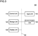
- Fig. 3 is a block diagram illustrating a hardware configuration of the target object detection apparatus.
- the target object detection apparatus 100 includes a control unit 110, a storage unit 120, a display unit 130, an input unit 140, and a communication unit 150. Those components are connected with each other via a bus 160.
- the control unit 110 which includes a CPU (central processing unit), controls the other components of the target object detection apparatus 100 and performs arithmetic processing in accordance with programs. Details of functions of the control unit 110 will be given later.
- the storage unit 120 can include a RAM (random access memory), a ROM (read only memory), and an SSD (solid state drive).
- the RAM serving as a workspace of the control unit 110 temporally stores therein programs and data.
- the ROM previously stores various kinds of programs and various kinds of data.
- the SSD holds various kinds of programs and various kinds of data including an operating system.
- the storage unit 120 stores therein area-by-area estimation parameters to which divisional areas resulting from division of the photographed image 250 into plural areas (hereinafter simply referred to as "divisional areas") and dictionaries corresponding to the divisional areas respectively, are set.
- Divisional areas can be determined by coordinates of pixels included in plural areas of the photographed image 250 having been divided, for example.
- Dictionaries are data that defines a weight given between nodes in respective layers of a DNN. Reflecting dictionaries in the DNN makes the DNN a learned model.
- one of dictionaries corresponding to the divisional area is reflected in the DNN and the target person 500 is detected from a feature map (convolutional feature map) described later.
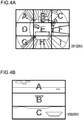
- Figs. 4A and 4B illustrate examples of divisional areas.
- Fig. 4A illustrates an example of the divisional areas set in the wide-angle image 251.
- Fig. 4B illustrates an example of the divisional areas set in the wide-range photographed image 252.
- one rectangular divisional area set at the center of the wide-angle image 251 an area denoted by gray "E”
- eight rectangular divisional areas set around the one rectangular divisional area areas denoted by gray "A" to "D” and "F” to “I”
- divisional areas are set such that they are classified into an area with relatively small distortion and an area with relatively large distortion in the wide-angle image 251.
- its corresponding area-by-area estimation parameter is used for each of the divisional areas.
- different area-by-area estimation parameters are used for an area with relatively slight distortion and for an area with relatively serious distortion in the wide-angle image 251, respectively.
- the divisional areas are set such that they are classified into the upper portion of the wide-range photographed image 252 where the ratio between the size of the object on the wide-range photographed image 252 and the actual size of the object is high, the lower portion of the wide-range photographed image 252 where the above-stated ratio is low, and the middle portion of the wide-range photographed image 252 where the above-stated ratio is middle between those in the upper and lower portions.
- different area-by-area parameters are used depending on the ratio between the size of the object on the wide-range photographed image 252 and the actual size of the object.
- the display unit 130 is a liquid-crystal display, for example, and displays various kinds of information
- the input unit 140 includes a touch panel or various kinds of keys, for example.
- the input unit 140 is used for various kinds of operations and inputting.
- the communication unit 150 is an interface for communicating with external apparatuses.
- a network interface complying with standards such as Ethernet (registered trademark), SATA, PCI, Express, USB, or IEEE 1394 can be used.
- a wireless communication interface complying with standards such as Bluetooth (registered trademark), IEEE 802.11, or 4G can be used.
- the communication unit 150 receives the photographed image 250 from the photographing apparatus 200.
- the communication unit 150 transmits the notice of event to the mobile terminal 400.
- the communication unit 150 transmits the detection result of the target person 500 detected from the photographed image 250, to the mobile terminal 400. Further, the communication unit 150 can transmit the detection results of posture and behavior of the target person 500 to the mobile terminal 400.
- control unit 110 Details of functions of the control unit 110 will be given.
- Fig. 5 is a block diagram illustrating functions of the control unit of the target object detection apparatus.
- the control unit 110 includes an image acquisition unit 111, a target object detection unit 112, a joint estimation unit 113, a behavior estimation unit 114, and an output unit 115.
- the image acquisition unit 111 forms an acquisition unit.
- the target object detection unit 112 forms a feature-map generation unit, a detection unit, an object detector, and a target object detector.
- the image acquisition unit 111 acquires the photographed image 250 received from the photographing apparatus 200 via the communication unit 150.
- the target object detection unit 112 detects the target person 500 from the photographed image 250 in the following manner.
- a convolution operation of the photographed image 250 by the DNN is performed, to generate a feature map in which features of pixels are extracted.
- Area-by-area estimation parameters are read out from the storage unit 120.
- the target person 500 is detected from the feature map by using the DNN in which the dictionary corresponding to the divisional area is reflected. More specifically, in each of divisional areas, an area where an object is present on the photographed image 250 is detected from the feature map as the candidate rectangle 253 by using the DNN, and the category of the object included in the candidate rectangle 253 is estimated.
- the candidate rectangle 253 including the object of which category has been estimated to be a person is detected as the output rectangle 254 including the target person 500.
- a method of detecting the candidate rectangle 253 and the output rectangle 254 from the feature map will be described in detail.
- Fig. 6 is an explanatory view for explaining a method of detecting the candidate rectangle based on the feature map.
- Fig. 7 is an explanatory view for explaining an example of the candidate rectangle.
- a part corresponding to the divisional area in the feature map 116 is illustrated as the feature map 116.
- grids 117 are set as local areas. Each of the grids 117 is brought into correspondence to anchors 118 that are reference rectangles on the photographed image 250. Each of the grids 117 is brought into correspondence to a plurality of anchors 118, each of which having a predetermined shape. The shapes of the plurality of anchors 118 may differ from local area to local area.
- a probability of presence of the object in each of the anchors 118 is estimated by the DNN in which the dictionary corresponding to the divisional area is reflected, and one of the anchors 118 that has the highest probability of presence of the object therein is determined.
- An amount of positional shift and an amount of scale shift of the determined anchor 118 with respect to a rectangular area where the object is present, are estimated. Then, those amounts of shift are minimized to detect the candidate rectangle 253.
- the candidate rectangles 253 including objects, i.e., a person, a bed, a desk, a chair, a walker, a television, a fan, and the like, respectively, are shown. Additionally, some objects (for example, moving objects such as animals) may be detected as the candidate rectangles 253.
- objects i.e., a person, a bed, a desk, a chair, a walker, a television, a fan, and the like, respectively. Additionally, some objects (for example, moving objects such as animals) may be detected as the candidate rectangles 253.
- the target object detection unit 112 calculates respective reliability scores of predetermined categories in each of the candidate rectangles 253 having been detected.
- the reliability score is a likelihood of each predetermined category.
- Predetermined categories are set to any categories including the person that is the category of the target person 500. Predetermined categories can be a person, a chair, a desk, and an instrumental, for example.
- the target object detection unit 112 detects the candidate rectangle 253 in which the category having the highest reliability score is the person, as the output rectangle 254.
- the target object detection unit 112 outputs the detected output rectangle 254 together with the calculated reliability scores of categories.
- Fig. 8 is a view illustrating an example of the output rectangle 254 output as the detection result of the target person.
- the detection result of the target person 500 in the wide-angle image 251 is shown.
- the output rectangle 254 output as the detection result is accompanied with a note indicating respective reliability scores of predetermined categories.
- the reliability score of a person category is 0.9
- the reliability score of an instrument category is 0.1
- the reliability score of each of the other categories is 0.
- the target person 500 is detected because the candidate rectangle 253 in which the reliability score of the person category is the highest has been detected as the output rectangle 254.
- only the target person 500 is defined as the target object as described above, and thus any of the candidate rectangles 253 in which the reliability score of the category other than a "person" is the highest is not detected as the output rectangle 254.
- the target person 500 in each of the divisional areas resulting from division of the photographed image 250, the target person 500 is detected from the feature map 116 generated from the photographed image 250 by using the dictionary corresponding to the divisional area. This can reduce false detection of the object due to variation in the object with areas in the photographed image 250. In contrast, in a case where the target person 500 is detected from the feature map 116 by using the same dictionary in all of areas in the photographed image 250, false detection of the object due to variation in the object with areas in the photographed image 250 can occur.
- the reliability score of the person in the candidate rectangle 253 including the walker is increased relative to reliability scores of the other categories, which can cause the walker to be falsely detected as the person.
- the feature map 116 is generated from the whole of the photographed image 250, and the feature map 116 for each of divisional areas is not generated.
- the single feature map 116 is shared in respective processes of detecting the target person 500 from the divisional areas, and the feature map 116 for each of divisional areas is not generated. This allows the target person 500 to be detected at a high speed and with high accuracy.
- the joint estimation unit 113 estimates the joints 119 as a posture of the target person 500, based on the output rectangle 254, and outputs the estimated joints 119 to the behavior estimation unit 114 as a detection result of the joints 119.
- the joint estimation unit 113 can estimate the joints 119 based on the output rectangle 254 by a known method using a DNN.
- Fig. 9 is an explanatory view illustrating an example of estimated joints.
- the joints 119 are shown while being superposed on the photographed image 250 and the positions of the joints 119 are indicated by outlined circles.
- the joints 119 include the joints 119 of a head, a neck, shoulders, elbows, hands, a waist, thighs, knees, and feet, for example.
- it can be recognized that the target person 500 is in a sitting posture, from positional relationships among the joints 119.
- the behavior estimation unit 114 estimates the behavior of the target person 500 based on the joints 119 estimated by the joint estimation unit 113 and outputs the estimated behavior to the output unit 115, as a detection result of behavior of the target person 500.
- the behavior estimation unit 114 can estimate the behavior of the target person 500 based on time variation in the joints 119 estimated from the plurality of photographed images 250. For example, in a case where an average speed of each of the joints 119 is rapidly reduced and a posture recognized from the joints 119 after the reduction of the average speed is decubitus, the behavior estimation unit 114 can estimate the behavior of the target person 500 to be "falling".
- the output unit 115 outputs the output rectangle 254 that is detected by the target object detection unit 112, the joints 119 of the target person 500 that are detected by the joint estimation unit 113, and the behavior of the target person 500 that is detected by the behavior estimation unit 114.
- Fig. 10 is a flowchart illustrating operations of the target object detection apparatus 100. Steps in the flowchart are preformed by the control unit 110 in accordance with a program stored in the storage unit 120.
- the control unit 110 causes the storage unit 120 to store area estimation parameters (S101).
- the control unit 110 acquires the photographed image 250 from the photographing apparatus 200 via the communication unit 150 (S102).
- the control unit 110 generates the feature map from the photographed image 250 by using the DNN (S103).
- the control unit 110 switches the area-by-area estimation parameters used for detecting the target person 500 by selection.
- the control unit 110 can select area-by-area parameters based on the distortion characteristics of the wide-angle camera.
- the distortion characteristics of the wide-angel camera are identified by the model number of the wide-angle camera.
- area-by-area parameters to which the divisional areas are set in accordance with the distortion characteristics of the wide-angle camera are previously stored in the storage unit 120 so as to correspond to the model number of the wide-angle camera,.
- the control unit 110 can select area-by-area parameters correspond to the model number of the wide-angle camera that are included in data of the photographed image 250 acquired from the wide-angle camera.
- the control unit 110 may cause the display unit 130 to display a screen that accepts inputting of distortion characteristics of a wide-angle camera of the photographing apparatus 200, to select area-by-area parameters to which the divisional areas are set in accordance with the distortion characteristics, based on the distortion characteristics input by a user in the input unit 140.
- the control unit 110 may select area-by-area parameters based on an installation height of the wide-angle camera of the photographing apparatus 200. For example, for each installation height of the wide-angle camera, area-by-area parameters to which the divisional areas are set in accordance with the installation height are previously stored in the storage unit 120 so as to correspond to the installation height in the storage unit 120.
- CAD Computer-Aided Design
- the control unit 110 calculates the height of a ceiling on which the wide-angle camera is installed in the room. Then, the control unit 110 can acquire area-by-area parameters to which the divisional areas are set in accordance with the installation height equal to the calculated height.
- the control unit 110 may cause the display unit 130 to display a screen that accepts inputting of an installation height of the wide-angle camera of the photographing apparatus 200, to select area-by-area parameters to which the divisional areas are set in accordance with the installation height, based on the installation height input by the user in the input unit 140.
- the control unit 110 can select area-by-area parameters based on an extent of a photographing range of the photographing apparatus 200. For example, for each extent of the photographing range of the wide-range photographed image 252, area-by-area parameters to which the divisional areas are set in accordance with the extent of the photographing range are previously stored in the storage unit 120 so as to correspond to the extent of the photographing range.
- the control unit 110 can cause the display unit 130 to display a screen that accepts inputting of the extent of the photographing range (a photographing area or an angle of view, for example) of the wide-range photographing camera of the photographing apparatus 200, to select area-by-area parameters to which the divisional areas are set in accordance with the extent of the photographing range, based on the extent of the photographing range input by the user in the input unit 140.
- the control unit 110 may select area-by-area parameters based on the installation height of the wide-range photographing camera of the photographing apparatus 200. For example, for each installation height of the wide-range photographing camera, area-by-area parameters to which the divisional areas are set in accordance with the installation height are previously stored in the storage unit 120 so as to correspond to the installation height.
- the CAD data of the facility is previously stored in the storage unit 120.
- the control unit 110 calculates the height of a ceiling on which the wide-range photographing camera is installed in the room. Then, the control unit 110 can acquire area-by-area parameters to which the divisional areas are set in accordance with the installation height equal to the calculated height.
- the control unit 110 may cause the display unit 130 to display a screen that accepts inputting of the installation height of the wide-range photographing camera of the photographing apparatus 200, to select area-by-area parameters to which the divisional areas are set in accordance with the installation height, based on the installation height input by a user in the input unit 140.
- the control unit 110 detects the candidate rectangle 253 including the object from the feature map in each of divisional areas by using the dictionary corresponding to the divisional area, based on area-by-area estimation parameter (S105).
- the control unit 110 calculates respective reliability scores of predetermined categories in each of the candidate rectangles 253 and detects the output rectangle 254, thereby detecting the target person 500 (S106).
- the control unit 110 transmits the output rectangle 254 and the respective reliability scores of the predetermined categories in the output rectangle 254 to the mobile terminal 400 or performs the other like operations, to achieve outputting (S107).
- the target object is detected from the feature map generated from the photographed image by using the dictionary corresponding to the divisional area. This can reduce false detection of the target object due to variation in the target object with areas in the photographed image, thereby detecting the target object at a high speed and with high accuracy.
- the divisional areas are set in accordance with the degree of distortion varying with positions on the image that is the wide-angle image.
- the photographed image is the wide-angle image
- the photographed image is the image in which the ratio between the size of an object on the photographed image and the actual size of the object varies with the distance from the camera that photographs the image to the object in the photographing direction, and the divisional areas are set in accordance with the ratio between the size of the object on the photographed image and the actual size of the object.
- the photographed image is the wide-range photographed image in which the ratio between the size of the object on the photographed image and the actual size of the object varies, it is possible to reduce false detection of the target object due to variation in the ratio between the size of the object on the photographed image and the actual size of the object in each area of the wide-range photographed image, thereby detecting the target object at a high speed and with high accuracy.
- respective reliability scores of predetermined object categories are calculated in each of the divisional areas by using the dictionary corresponding to the divisional area, thereby detecting the target object.
- the object is detected from the feature map in each of divisional areas by using the dictionary corresponding to the divisional area, and thereafter respective reliability scores of predetermined categories are calculated for each of the detected objects, thereby detecting the target object from the objects.
- the object is detected from the feature map in each of divisional areas by using the dictionary corresponding to the divisional area, and thereafter respective reliability scores of predetermined categories are calculated for each of the detected objects, thereby detecting the target object from the objects.
- the amount of the positional shift and the amount of scale shift of the reference rectangle set in the photographed image with respect to the rectangular area where the object is present are estimated in each of divisional areas by using the feature map and the dictionary, and the amount of positional shift and the amount of scale shift are minimized to detect the candidate rectangle 253.
- respective reliability scores of the predetermined categories are calculated for the object included in the candidate rectangle 253, and the candidate rectangle in which the category having the highest reliability score is the category of the target object is estimated as an output rectangle including the target object, thereby detecting the target object.
- the shape of the reference rectangle varies with the divisional areas. This allows a target object to be detected more simply, at a high speed and with high accuracy by using Faster R-CNN.
- the area-by-area estimation parameters used for detecting the target object are switched to the area-by-area estimation parameters to which the divisional areas are set in accordance with the distortion characteristics of the lens. This allows the target object to be detected from the wide-angle image in a simpler procedure, at a high speed, and with high accuracy.
- the area-by-area estimation parameters used for detecting the target object are switched to the area-by-area estimation parameters to which the divisional areas in accordance with the installation height of the camera are set. This allows the target object to be detected from the wide-angle image in a simpler procedure, at a high speed, and with high accuracy.
- area-by-area estimation parameters used for detecting the target object are switched to the area-by-area estimation parameters to which the divisional areas in accordance with the extent of the photographing range are set. This allows the target object to be detected from the wide-range photographed image in a simpler procedure, at a high speed, and with high accuracy.
- either the photographing apparatus 200 including the sensor box or the mobile terminal 400 may have the functions of the target object detection apparatus 100.
- each of the target object detection apparatus 100, the photographing apparatus 200, and the mobile terminal 400 may include a plurality of apparatuses and the plurality of apparatuses forming any of the apparatuses 100, 200, and 400 may be configured as a single apparatus.
- a part of steps may be omitted, or another step may be added. Moreover, a part of the steps may be performed at the same time, and a single step may be divided into plural steps and performed.
- the target object is not limited to a person, and may be a ship, a cat, a dog, and the like.
- the target object may include a plurality of categories.
- components and the method for performing various kinds of processing in the above-described target object detection system 10 can be implemented by either a dedicated hardware circuit or a computer loaded with programs.
- the programs may be provided by a computer-readable recording medium such as a USB memory or a DVD (digital versatile disc)-ROM, for example, or may be provided on-line via a network such as the Internet.
- programs recorded on a computer-readable recording medium are typically transferred to and stored in a storage unit such as a hard disc.
- the programs may be provided in the form of independent application software or may be incorporated into software of a device such as the detection unit or the like, as one of functions.
Landscapes
- Engineering & Computer Science (AREA)
- Theoretical Computer Science (AREA)
- Physics & Mathematics (AREA)
- General Physics & Mathematics (AREA)
- Multimedia (AREA)
- Computer Vision & Pattern Recognition (AREA)
- General Health & Medical Sciences (AREA)
- Evolutionary Computation (AREA)
- Health & Medical Sciences (AREA)
- Artificial Intelligence (AREA)
- Human Computer Interaction (AREA)
- Software Systems (AREA)
- Molecular Biology (AREA)
- Computing Systems (AREA)
- Biomedical Technology (AREA)
- Life Sciences & Earth Sciences (AREA)
- Medical Informatics (AREA)
- Social Psychology (AREA)
- Biodiversity & Conservation Biology (AREA)
- Databases & Information Systems (AREA)
- Psychiatry (AREA)
- Biophysics (AREA)
- Computational Linguistics (AREA)
- Data Mining & Analysis (AREA)
- General Engineering & Computer Science (AREA)
- Mathematical Physics (AREA)
- Image Analysis (AREA)
Applications Claiming Priority (2)
| Application Number | Priority Date | Filing Date | Title |
|---|---|---|---|
| JP2018126305 | 2018-07-02 | ||
| PCT/JP2019/018629 WO2020008726A1 (fr) | 2018-07-02 | 2019-05-09 | Programme de détection d'objet cible et dispositif de détection d'objet cible |
Publications (2)
| Publication Number | Publication Date |
|---|---|
| EP3819864A1 true EP3819864A1 (fr) | 2021-05-12 |
| EP3819864A4 EP3819864A4 (fr) | 2021-08-18 |
Family
ID=69060638
Family Applications (1)
| Application Number | Title | Priority Date | Filing Date |
|---|---|---|---|
| EP19830090.7A Withdrawn EP3819864A4 (fr) | 2018-07-02 | 2019-05-09 | Programme de détection d'objet cible et dispositif de détection d'objet cible |
Country Status (3)
| Country | Link |
|---|---|
| EP (1) | EP3819864A4 (fr) |
| JP (1) | JP7243725B2 (fr) |
| WO (1) | WO2020008726A1 (fr) |
Families Citing this family (2)
| Publication number | Priority date | Publication date | Assignee | Title |
|---|---|---|---|---|
| WO2023181277A1 (fr) * | 2022-03-24 | 2023-09-28 | ファナック株式会社 | Dispositif d'inspection d'aspect, procédé d'inspection d'aspect et support d'enregistrement lisible par ordinateur |
| JP7365729B1 (ja) | 2022-10-06 | 2023-10-20 | 株式会社アジラ | 姿勢推定システム |
Family Cites Families (5)
| Publication number | Priority date | Publication date | Assignee | Title |
|---|---|---|---|---|
| JP5739722B2 (ja) | 2011-04-26 | 2015-06-24 | 株式会社日立情報通信エンジニアリング | 物体認識方法及び認識装置 |
| JP5477394B2 (ja) | 2012-01-10 | 2014-04-23 | 株式会社デンソー | 車両周辺監視装置 |
| JP2016171526A (ja) * | 2015-03-13 | 2016-09-23 | 株式会社東芝 | 画像センサ、人検出方法、制御システム、制御方法及びコンピュータプログラム |
| US9858496B2 (en) | 2016-01-20 | 2018-01-02 | Microsoft Technology Licensing, Llc | Object detection and classification in images |
| JP6679512B2 (ja) | 2017-02-08 | 2020-04-15 | 株式会社オリンピア | 遊技機 |
-
2019
- 2019-05-09 EP EP19830090.7A patent/EP3819864A4/fr not_active Withdrawn
- 2019-05-09 JP JP2020528701A patent/JP7243725B2/ja active Active
- 2019-05-09 WO PCT/JP2019/018629 patent/WO2020008726A1/fr not_active Ceased
Also Published As
| Publication number | Publication date |
|---|---|
| JPWO2020008726A1 (ja) | 2021-07-08 |
| JP7243725B2 (ja) | 2023-03-22 |
| EP3819864A4 (fr) | 2021-08-18 |
| WO2020008726A1 (fr) | 2020-01-09 |
Similar Documents
| Publication | Publication Date | Title |
|---|---|---|
| US11298050B2 (en) | Posture estimation device, behavior estimation device, storage medium storing posture estimation program, and posture estimation method | |
| US7106885B2 (en) | Method and apparatus for subject physical position and security determination | |
| CN105283129B (zh) | 信息处理装置、信息处理方法 | |
| CN111212220B9 (zh) | 保存有图像处理程序的记录介质以及图像处理装置 | |
| JP6822328B2 (ja) | 見守り支援システム及びその制御方法 | |
| US20190313948A1 (en) | Monitoring assistance system, control method thereof, and program | |
| EP3855451A1 (fr) | Système de vision artificielle pour prédire les paramètres cliniques d'un patient | |
| CN115331283A (zh) | 用于检测人在生活空间中跌倒的检测系统及其检测方法 | |
| JP2022139507A (ja) | 検知装置、検知方法、および学習モデル生産方法 | |
| JP7314939B2 (ja) | 画像認識プログラム、画像認識装置、学習プログラム、および学習装置 | |
| Albawendi et al. | Video based fall detection using features of motion, shape and histogram | |
| JP7347577B2 (ja) | 画像処理システム、画像処理プログラム、および画像処理方法 | |
| JP7530222B2 (ja) | 検知装置、検知方法、画像処理方法、およびプログラム | |
| JP7243725B2 (ja) | 対象物体検出プログラム、および対象物体検出装置 | |
| JP2018082745A (ja) | 姿勢判定装置及び通報システム | |
| JP2021033379A (ja) | 画像処理システム、画像処理プログラム、および画像処理方法 | |
| JP2020134971A (ja) | 現場学習評価プログラム、現場学習評価方法、および現場学習評価装置 | |
| JP7435609B2 (ja) | 画像処理システム、画像処理プログラム、および画像処理方法 | |
| JP7351339B2 (ja) | 画像処理システム、画像処理プログラム、および画像処理方法 | |
| JP2021065617A (ja) | 画像処理装置および画像処理プログラム | |
| JP7388440B2 (ja) | 画像処理システム、画像処理プログラム、および画像処理方法 | |
| JP7608180B2 (ja) | 特定動作検出装置 | |
| EP4394725A1 (fr) | Procédure et système de surveillance des personnes alitées et des personnes se reposant dans leur lit | |
| JP2024160736A (ja) | 見守り装置、制御方法、および制御プログラム | |
| JP2025124118A (ja) | 介護システム、および制御プログラム |
Legal Events
| Date | Code | Title | Description |
|---|---|---|---|
| STAA | Information on the status of an ep patent application or granted ep patent |
Free format text: STATUS: THE INTERNATIONAL PUBLICATION HAS BEEN MADE |
|
| PUAI | Public reference made under article 153(3) epc to a published international application that has entered the european phase |
Free format text: ORIGINAL CODE: 0009012 |
|
| STAA | Information on the status of an ep patent application or granted ep patent |
Free format text: STATUS: REQUEST FOR EXAMINATION WAS MADE |
|
| 17P | Request for examination filed |
Effective date: 20201125 |
|
| AK | Designated contracting states |
Kind code of ref document: A1 Designated state(s): AL AT BE BG CH CY CZ DE DK EE ES FI FR GB GR HR HU IE IS IT LI LT LU LV MC MK MT NL NO PL PT RO RS SE SI SK SM TR |
|
| A4 | Supplementary search report drawn up and despatched |
Effective date: 20210715 |
|
| RIC1 | Information provided on ipc code assigned before grant |
Ipc: G06T 7/00 20170101AFI20210709BHEP Ipc: G06K 9/00 20060101ALI20210709BHEP Ipc: G06K 9/32 20060101ALI20210709BHEP Ipc: G06K 9/46 20060101ALI20210709BHEP Ipc: G06N 3/02 20060101ALI20210709BHEP |
|
| DAV | Request for validation of the european patent (deleted) | ||
| DAX | Request for extension of the european patent (deleted) | ||
| P01 | Opt-out of the competence of the unified patent court (upc) registered |
Effective date: 20230510 |
|
| STAA | Information on the status of an ep patent application or granted ep patent |
Free format text: STATUS: EXAMINATION IS IN PROGRESS |
|
| 17Q | First examination report despatched |
Effective date: 20230809 |
|
| REG | Reference to a national code |
Ref country code: DE Ref legal event code: R079 Free format text: PREVIOUS MAIN CLASS: G06T0007000000 Ipc: G06V0020520000 |
|
| GRAP | Despatch of communication of intention to grant a patent |
Free format text: ORIGINAL CODE: EPIDOSNIGR1 |
|
| STAA | Information on the status of an ep patent application or granted ep patent |
Free format text: STATUS: GRANT OF PATENT IS INTENDED |
|
| RIC1 | Information provided on ipc code assigned before grant |
Ipc: G06V 20/52 20220101AFI20250723BHEP Ipc: G06V 40/20 20220101ALI20250723BHEP Ipc: G06V 40/10 20220101ALI20250723BHEP Ipc: G06V 10/25 20220101ALI20250723BHEP Ipc: G06V 10/44 20220101ALI20250723BHEP Ipc: G06V 10/50 20220101ALI20250723BHEP Ipc: G06V 10/82 20220101ALI20250723BHEP Ipc: G06T 7/73 20170101ALI20250723BHEP |
|
| INTG | Intention to grant announced |
Effective date: 20250806 |
|
| STAA | Information on the status of an ep patent application or granted ep patent |
Free format text: STATUS: THE APPLICATION IS DEEMED TO BE WITHDRAWN |
|
| 18D | Application deemed to be withdrawn |
Effective date: 20251209 |