EP3819925B1 - Ensemble de support d'isolation améliorée pour disjoncteur - Google Patents
Ensemble de support d'isolation améliorée pour disjoncteur Download PDFInfo
- Publication number
- EP3819925B1 EP3819925B1 EP19306438.3A EP19306438A EP3819925B1 EP 3819925 B1 EP3819925 B1 EP 3819925B1 EP 19306438 A EP19306438 A EP 19306438A EP 3819925 B1 EP3819925 B1 EP 3819925B1
- Authority
- EP
- European Patent Office
- Prior art keywords
- circuit breaker
- main body
- shaped
- arrangement according
- metallic
- Prior art date
- Legal status (The legal status is an assumption and is not a legal conclusion. Google has not performed a legal analysis and makes no representation as to the accuracy of the status listed.)
- Active
Links
Images



Classifications
-
- H—ELECTRICITY
- H01—ELECTRIC ELEMENTS
- H01H—ELECTRIC SWITCHES; RELAYS; SELECTORS; EMERGENCY PROTECTIVE DEVICES
- H01H33/00—High-tension or heavy-current switches with arc-extinguishing or arc-preventing means
- H01H33/02—Details
-
- H—ELECTRICITY
- H01—ELECTRIC ELEMENTS
- H01H—ELECTRIC SWITCHES; RELAYS; SELECTORS; EMERGENCY PROTECTIVE DEVICES
- H01H1/00—Contacts
- H01H1/12—Contacts characterised by the manner in which co-operating contacts engage
- H01H1/36—Contacts characterised by the manner in which co-operating contacts engage by sliding
- H01H1/38—Plug-and-socket contacts
- H01H1/385—Contact arrangements for high voltage gas blast circuit breakers
-
- H—ELECTRICITY
- H01—ELECTRIC ELEMENTS
- H01H—ELECTRIC SWITCHES; RELAYS; SELECTORS; EMERGENCY PROTECTIVE DEVICES
- H01H33/00—High-tension or heavy-current switches with arc-extinguishing or arc-preventing means
- H01H33/60—Switches wherein the means for extinguishing or preventing the arc do not include separate means for obtaining or increasing flow of arc-extinguishing fluid
- H01H33/64—Switches wherein the means for extinguishing or preventing the arc do not include separate means for obtaining or increasing flow of arc-extinguishing fluid wherein the break is in gas
Definitions
- the present invention relates to a switching chamber insulation arrangement for a High Voltage (HV) circuit breaker.
- HV High Voltage
- it relates to an improved insulator for support and alignment of a high-voltage circuit breaker interrupter.
- high-voltage circuit breakers are mechanical switching devices which connect and break current circuits. They contain one or more interrupter units and each interrupter unit has two sub-assemblies, each containing a contact pole. The two contact poles can be moved relative to one another between a connection position and a disconnection position in which the two contact poles are separated by a gap.
- an insulating support is necessary across the two sub-assemblies of the interrupter. This insulating support enables the implementation of a single, self-supporting interrupter that can be fully assembled and aligned on a bench and then inserted into a tank of a circuit breaker.
- this insulating support is obtained by an arrangement of tubular insulation elements (struts 10, 20) which are set across the interrupter gap, their foot points 11, 21 and 13, 23 being attached to their respective contact poles 1, 2, for example by a screw connection.
- the circuit breaker has a housing 101, which surrounds a gas area 9, two contact poles 1 and 2 of the circuit breaker which are located within this gas area and the first contact pole 1 has a moving part 1a, which can be moved axially along a longitudinal extent direction L.
- FIG. 2 shows another exemplary embodiment of the prior art with an arrangement of four struts 10, 20, 30, 40, arranged along a circumference U and configured to be assembled to their respective contact pole along this circumference U (in the direction of the bold arrows, which are parallel to the longitudinal L direction).
- Such insulation support in the form of a strut or arrangement of a plurality of struts offers the advantage of not enclosing the interrupter gap, allowing for particulates generated by the interrupter during breaker operation to exit the zone of the interrupter gap and fall on the inner surface of the grounded housing of the tank.
- Such improved insulating support could also be used to provide electrical insulation and mechanical support between other parallel components of a circuit breaker, while maintaining a minimum radial dimension of the thus connected components.
- An object of the present invention is a circuit breaker insulation arrangement comprising at least one insulating support assembly and two components of a circuit breaker, the insulating support assembly configured to provide mechanical support and electrical insulation between two components of a circuit breaker, the insulating support assembly comprising a strut and two metallic shields, the strut comprising:
- the curvature of the main body is constant.
- the elongated main body has a C-shaped or substantially C-shaped profile.
- the elongated main body having a C-shaped or substantially C-shaped profile, the C-shaped or substantially C-shaped profiles of the shields are parallel and the plans containing the C-shaped or substantially C-shaped profiles of the shields are oriented at an angle of 90° with respect to the plane containing the C-shaped or substantially C-shaped profile of the main body.
- the elongated main body having a C-shaped or substantially C-shaped profile, one of the two C-shaped or substantially C-shaped profiles of the shields and the C-shaped or substantially C-shaped profile of the main body are in a same plane and this plane is oriented to an angle of 90° with respect to a plane containing the other one of the two C-shaped or substantially C-shaped profiles of the shields.
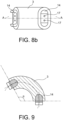
- an angle ⁇ (see for example in FIG. 9 ) between the two ends of the main body is comprised between 60° and 180° inclusive; preferably, the angle is comprised between 120° and 180° inclusive when the assembly has to provide mechanical support and electrical insulation between two interrupter sub-assemblies and between 60° and 120° inclusive when the assembly has to provide mechanical support and electrical insulation between a circuit breaker contact and a component which is a grading capacitor or a pre-insertion resistor.
- the circuit breaker insulation arrangement comprises at least three insulating support assemblies.
- one of the two components is a circuit breaker contact and the other one of the two components is a grading capacitor, a surge arrester or a pre-insertion resistor.
- Such a configuration is adapted, for example, for fitting a pre-insertion resistor with an additional insertion contact, the pre-insertion resistor and the insertion contact being connected in series with one or more insulating support assemblies.
- the two components might be adjacent, the longitudinal axis of one of the two components being parallel to the longitudinal axis of the other one of the two components.
- the two components are either two interrupter sub-assemblies, each containing a switch contact pole, or a circuit breaker contact and a grading capacitor or pre-insertion resistor):
- the insulating support assembly according to the invention can be used to provide mechanical support, as well as alignment and insulation across two components of a circuit breaker.
- the insulating support assembly can be used as a gap insulator to provide mechanical support, alignment and electrical insulation across the interrupter gap, while maintaining a minimum radial dimension of the interrupter and of the tank. It allows for a reduction in costs of the interrupter and the tank as a result of smaller radial dimensions. Furthermore, the curved form of the strut increases the strike distance and creepage distance, improving performance under polluted conditions.
- a plurality of insulating support assemblies can be used to connect to interrupter sub-assemblies 1, 2.
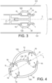
- two insulating support assemblies 12, 22 are arranged across the interrupter gap and the metallic shields are fixed around the perimeter of the interrupter sub-assemblies 1, 2.
- FIG. 4 is illustrated another exemplary of an arrangement according to the invention of three insulating support assemblies 12, 22, 32, each insulating support assembly 12, 22, 32 comprising a strut 120, 122, 132 and two metallic shields 15.
- the metallic shields 15 are arranged along a circumference U and configured to be assembled and fixed to their respective components (here interrupter sub-assemblies) along this circumference U (in the direction of the bold arrows, which are oriented in a radial direction relative to the longitudinal L direction).
- the insulating support assembly 12 comprises a strut 120 and two metallic shields 15.
- the strut 120 comprises an electrically insulating curved main body 3, made of a vacuum casted epoxy resin, and two metallic inserts 14, each insert being partially embedded at one end of the main body.
- Each metallic shield 15 is configured to be assembled with its respective metallic insert 14 on an outer surface of a component 1, 2 of a circuit breaker 100.
- the shield and the insert comprise holes or through-holes 17 for the insertion of fixing elements such as bolts or screws.
- the two metallic inserts 14 are included in the casting process of the main body 3 so that they are partially integrated in the main body.
- a metallic insert 14 and its respective shield 15 are two separate elements, the shield and the insert are assembled together, for example bolted together, and the shield is then assembled on the outer surface of its respective component.
- the insert and its respective shield can also be integrated into a single piece 16.
- An advantage of an integrated insert is that the insulating support assembly can be assembled on the outer surface of the component from the outer side of the component that it is intended to be joined to and support.
- the metallic shields 15 are used to fix the end of the inserts 14 on a component of a circuit breaker by means of fixing elements (such as bolts or screws), but they also serve as shields for the heads of the fixing elements against fuel peaks. Indeed, the fixing elements are inserted into holes 17 provided in the shields, so that the heads of the fixing elements are recessed in the shields and do not protrude from them. The fixing elements are thus shielded inside the shield body and the resulting electric field intensity is reduced.
- the preferred shape for the head of the fixing element is cylindrical (socket head type), which allows it to be recessed in a round countersunk hole.
- the metallic shields are configured to be affixed to the outer surface of the component on which it is to be fixed. Since the components have generally a tubular form, the shields will thus usually have a C-shaped profile.
- the profiles of two shields (for example C-shaped profiles) of a same strut can be oriented parallel to each other or differently, if necessary, depending on the orientation of the two components to be connected, in order to adapt to the profile of the outer surfaces of the components on which they are to be affixed. For example, as illustrated in FIG.
- the C-shaped profiles of the shields 15 are parallel and the plans containing the C-shaped profiles of the shields are oriented at an angle of 90° with respect to the plane containing the C-shaped profile of the main body of the strut.
- the C-shaped profile of one of the shields is parallel to the C-shaped profile of the main body and the plans of the C-shaped profiles of this shield and the main body are oriented at an angle of 90° with respect to the plane of the C-shaped profile of the other one of the shields.
- the main body 3 of the strut 120 is elongated and curved with a curvature 18 extending from one end of the main body to the other end and there is a metallic insert 14 partially embedded at each end of the main body.
- the main body of the strut has a C shape.
- the C shape actually allows for shorter spacing between the two shields 15, and thus between the two components to be joined by the strut, while still keeping a long distance along the insulator surface of the main body. This distance is important in order to avoid surface tracking under a voltage stress when the insulating support assembly is operating in polluted conditions.
- the breaking of currents creates decomposition products in the gas that is used for interruption and these form solid compounds that deposit on surfaces inside the circuit breaker, including on the surface of the main body of the strut.
- the main body 3 of the strut is made of an electrically insulating material, in particular a casted epoxy resin.
- Epoxy resin is the material that is most commonly used for solid electrical insulation in switchgear. In particular, it is used in Gas-Insulated Substations and in Metal Enclosed (dead-tank) circuit breakers.
- the epoxy resin is casted in a mold under a vacuum process in order to avoid voids or cavities in the material.
- the main body can have an ovoid or a circular cross section shape.
- the ovoid shape provides more mechanical strength in the direction in which the cross section is greater.
- the smallest dimension of the cross section of the main body is preferably greater than the greatest dimension of the cross section of the metallic insert 14. This configuration ensures that triple points are not protruding. As a reminder, triple points are regions where a solid dielectric material, a metal and a gas meet and these regions are very prone to electron emission under voltage. The configuration of the end fitting is such that the triple point is hidden behind the metal piece incorporated into the epoxy.
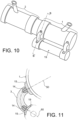
- the insulating support assemblies according to the invention can also be used to provide mechanical support to a graded capacitor 19 on an interrupter sub-assembly 1 (contact pole) in a high-voltage gas-insulated metal-enclosed circuit breaker.
- an interrupter sub-assembly 1 contact pole
- FIG. 5 the configuration illustrated in FIG. 5 is used here to connect the graded capacitor on the contact pole.
- a metallic shield 15 can be affixed on the outer surface of a component. Another option is to recess the entire metallic shield into the outer surface of the component. In the embodiment illustrated in FIG. 11 , one of the two metallic shields is affixed on the outer surface of the interrupter sub-assembly 1 and the other shield is recessed into the metal housing of the grading capacitor 19.
- one end of the main body 3 faces the radial direction 50 of the interrupter sub-assembly 1 and the other end of the main body 3 faces the radial direction 60 of the grading capacitor 19.
- the ends of the curved main body 3 have a 90° angle relative to the radial direction of its respective component.
- the grading capacitor 19 could be replaced with a pre-insertion resistor.
- the exposed surface of a shield 15 follows the contour of the outer surface of the component on which it is affixed and its perimeter is rounded to reduce the electric field intensity.
Landscapes
- Arc-Extinguishing Devices That Are Switches (AREA)
- Gas-Insulated Switchgears (AREA)
Claims (14)
- Agencement d'isolation de disjoncteur comprenant au moins un ensemble support isolant (12 ; 22 ; 32) et deux composants (1 ; 2) d'un disjoncteur (100), l'ensemble support isolant (12 ; 22 ; 32) étant configuré pour fournir un support mécanique et une isolation électrique entre les deux composants (1 ; 2) du disjoncteur (100), l'ensemble support isolant comprenant une entretoise (120 ; 122 ; 132) et deux blindages métalliques (15), l'entretoise comprenant :- un corps principal allongé (3) fait d'une résine époxy coulée sous vide présentant deux extrémités ; et- deux inserts métalliques (14), chaque insert étant partiellement intégré dans son extrémité respective du corps principal ;l'ensemble étant caractérisé en ce que le corps principal est incurvé de manière continue avec une courbure (18) s'étendant depuis une extrémité jusqu'à l'autre extrémité du corps principal, chaque extrémité du corps principal étant configurée pour faire face à une direction radiale du composant sur lequel elle doit être fixée, et le corps principal étant configuré pour être dans un même plan qu'un plan contenant les deux directions radiales des composants ; eten ce que chaque blindage métallique (15) est configuré pour être assemblé à son extrémité respective du corps principal (3) grâce à son insert métallique respectif (14) et fixé à une surface externe de son composant respectif (1 ; 2) du disjoncteur au moyen d'éléments de fixation, chaque blindage métallique présentant un profil en forme de C ou sensiblement en forme de C mis en forme pour accueillir la surface externe de son composant respectif.
- Agencement d'isolation de disjoncteur selon la revendication 1, dans lequel le corps principal allongé (3) présente un profil en forme de C ou sensiblement en forme de C.
- Agencement d'isolation de disjoncteur selon la revendication 2, dans lequel les profils en forme de C ou sensiblement en forme de C des blindages sont parallèles et les plans contenant les profils en forme de C ou sensiblement en forme de C des blindages sont orientés selon un angle de 90° par rapport au plan contenant le profil en forme de C ou sensiblement en forme de C du corps principal.
- Agencement d'isolation de disjoncteur selon la revendication 2, dans lequel un des deux profils en forme de C ou sensiblement en forme de C des blindages et le profil en forme de C ou sensiblement en forme de C du corps principal sont dans un même plan et ce plan est orienté selon un angle de 90° par rapport à un plan contenant l'autre des deux profils en forme de C ou sensiblement en forme de C des blindages.
- Agencement d'isolation de disjoncteur selon l'une quelconque des revendications 1 à 4, dans lequel un angle θ entre les deux extrémités du corps principal est compris entre 60° et 180° inclus.
- Agencement d'isolation de disjoncteur selon l'une quelconque des revendications 1 à 5, dans lequel une plus petite dimension d'une section transversale du corps principal (3) est plus grande qu'une plus grande dimension d'une section transversale de son insert métallique respectif (14).
- Agencement d'isolation de disjoncteur selon l'une quelconque des revendications 1 à 6, dans lequel au moins un blindage métallique (15) et son insert métallique respectif (14) sont intégrés dans un seul élément métallique (16).
- Agencement d'isolation de disjoncteur selon l'une quelconque des revendications 1 à 7, dans lequel le corps principal allongé (3) présente une section transversale ovoïde ou circulaire.
- Agencement d'isolation de disjoncteur selon l'une quelconque des revendications 1 à 8, dans lequel les deux composants (1 ; 2) du disjoncteur (100) sont deux sous-ensembles d'interrupteur, chaque sous-ensemble d'interrupteur contenant un pôle de contact d'interrupteur.
- Agencement d'isolation de disjoncteur selon la revendication 9, comprenant au moins trois ensembles supports isolants.
- Agencement d'isolation de disjoncteur selon l'une quelconque des revendications 1 à 8, dans lequel un des deux composants du disjoncteur est un contact de disjoncteur (1) et l'autre des deux composants est un condensateur de calibrage (19) ou une résistance de pré-insertion.
- Agencement d'isolation de disjoncteur selon l'une quelconque des revendications 9 à 11, dans lequel chaque insert métallique (14) est assemblé, à travers son blindage métallique respectif (15), sur la surface externe de son composant respectif dans une direction radiale dudit composant.
- Agencement d'isolation de disjoncteur selon l'une quelconque des revendications 9 à 12, dans lequel les blindages métalliques présentent des trous traversants (17) pour recevoir des éléments de fixation et sont fixés à leurs composants respectifs par les éléments de fixation, chaque élément de fixation étant évidé dans son trou traversant de manière à ne pas faire saillie d'une surface de son blindage métallique respectif.
- Agencement d'isolation de disjoncteur selon l'une quelconque des revendications 9 à 13, dans lequel au moins un blindage métallique (15) est logé dans un évidement dans la surface externe de son composant respectif du disjoncteur.
Priority Applications (2)
| Application Number | Priority Date | Filing Date | Title |
|---|---|---|---|
| EP19306438.3A EP3819925B1 (fr) | 2019-11-06 | 2019-11-06 | Ensemble de support d'isolation améliorée pour disjoncteur |
| US17/091,924 US11251003B2 (en) | 2019-11-06 | 2020-11-06 | Insulating support assembly for a circuit breaker |
Applications Claiming Priority (1)
| Application Number | Priority Date | Filing Date | Title |
|---|---|---|---|
| EP19306438.3A EP3819925B1 (fr) | 2019-11-06 | 2019-11-06 | Ensemble de support d'isolation améliorée pour disjoncteur |
Publications (2)
| Publication Number | Publication Date |
|---|---|
| EP3819925A1 EP3819925A1 (fr) | 2021-05-12 |
| EP3819925B1 true EP3819925B1 (fr) | 2025-04-02 |
Family
ID=68618102
Family Applications (1)
| Application Number | Title | Priority Date | Filing Date |
|---|---|---|---|
| EP19306438.3A Active EP3819925B1 (fr) | 2019-11-06 | 2019-11-06 | Ensemble de support d'isolation améliorée pour disjoncteur |
Country Status (2)
| Country | Link |
|---|---|
| US (1) | US11251003B2 (fr) |
| EP (1) | EP3819925B1 (fr) |
Family Cites Families (10)
| Publication number | Priority date | Publication date | Assignee | Title |
|---|---|---|---|---|
| US3816682A (en) * | 1972-03-14 | 1974-06-11 | Ite Imperial Corp | Two-pressure circuit breaker with contact cooling by the direct expansion of high-pressure dielectric gas |
| US4107498A (en) * | 1976-01-15 | 1978-08-15 | Westinghouse Electric Corp. | Disconnect switch and drive mechanism therefor |
| FR2592210B1 (fr) * | 1985-12-20 | 1990-07-27 | Merlin Gerin | Sectionneur d'isolement d'une installation blindee haute tension |
| JPH11224576A (ja) * | 1998-02-06 | 1999-08-17 | Nissin Electric Co Ltd | ガス遮断器 |
| DE29902208U1 (de) * | 1999-01-28 | 2000-08-17 | Siemens AG, 80333 München | Mehrphasig gekapselte Freiluft-Hochspannungsschalteinrichtung |
| US6495785B1 (en) * | 2000-06-29 | 2002-12-17 | Abb Power T&D Company Inc. | Non-glue mounting of non-metallic tubes |
| CN201527862U (zh) * | 2009-10-19 | 2010-07-14 | 山东彼岸电力科技有限公司 | 一种高压电器用绝缘支撑杆 |
| CN102770933A (zh) * | 2010-02-26 | 2012-11-07 | 三菱电机株式会社 | 电流断续器 |
| EP2390890B1 (fr) | 2010-05-28 | 2015-03-25 | ABB Technology AG | Agencement d'isolation de chambre de commutation pour un commutateur de puissance |
| EP2390887A1 (fr) * | 2010-05-28 | 2011-11-30 | ABB Technology AG | Commutateur de puissance |
-
2019
- 2019-11-06 EP EP19306438.3A patent/EP3819925B1/fr active Active
-
2020
- 2020-11-06 US US17/091,924 patent/US11251003B2/en active Active
Also Published As
| Publication number | Publication date |
|---|---|
| US11251003B2 (en) | 2022-02-15 |
| EP3819925A1 (fr) | 2021-05-12 |
| US20210134543A1 (en) | 2021-05-06 |
Similar Documents
| Publication | Publication Date | Title |
|---|---|---|
| JP7746529B2 (ja) | 真空遮断器、及び、複数の真空遮断器を備えたアセンブリ、並びに、複数の真空遮断器の電圧配分方法 | |
| US20150244156A1 (en) | Integrated compact bushing structure combining the functionality of primary contact with a current transformer primary conductor and a post insulator | |
| CN111480212B (zh) | 高压功率开关和用于电磁屏蔽绝缘子中的真空开关管的方法 | |
| JP6990294B2 (ja) | ガス絶縁型開閉装置用の回路遮断器 | |
| US4403125A (en) | Gas-insulated disconnecting switch | |
| DE3879981T2 (de) | Mehrphasenleistungsschalter mit Selbstausdehnung, ausgerüstet mit einer gekapselten Löschkammer je Phase. | |
| EP3905460A1 (fr) | Dispositif de connexion des barre omnibus | |
| US20070119818A1 (en) | Compressed-gas-insulated switch-disconnector module and bushing configuration | |
| US11251003B2 (en) | Insulating support assembly for a circuit breaker | |
| US10763062B2 (en) | Switching device with dual conductive housing | |
| JP2024527807A (ja) | 真空遮断器、及び、複数の真空遮断器を備えたアセンブリ、並びに、複数の真空遮断器の電圧配分方法 | |
| CN103181046B (zh) | 多极气体绝缘母线段 | |
| EP4027365B1 (fr) | Appareil de commutation pour systèmes électriques | |
| US20080105654A1 (en) | Polyphase Switching Device Comprising at Least Three Similar Interrupter Units | |
| KR102611655B1 (ko) | 가스 절연 개폐장치용 도체 | |
| KR102066227B1 (ko) | 가스절연 개폐장치 | |
| CN215815424U (zh) | 用于气体绝缘系统的间隔组件以及气体绝缘系统 | |
| KR19980070230A (ko) | 발전기 스위치 | |
| CN118783291A (zh) | 紧凑型开关设备 | |
| JPH0246113A (ja) | ガス絶縁断路器 | |
| JP2024147518A (ja) | 小型スイッチング機器 | |
| CN115938827A (zh) | 一种主母线导体、主母线导体组件和隔离接地开关 | |
| GB2538170A (en) | Manufactured piece for a gas-insulated high-voltage circuit breaker tank with particle traps and tank containing such a piece | |
| CN116598081A (zh) | 屏蔽结构、绝缘子和开关设备 | |
| JPS583563B2 (ja) | ゼツエントウ |
Legal Events
| Date | Code | Title | Description |
|---|---|---|---|
| PUAI | Public reference made under article 153(3) epc to a published international application that has entered the european phase |
Free format text: ORIGINAL CODE: 0009012 |
|
| STAA | Information on the status of an ep patent application or granted ep patent |
Free format text: STATUS: THE APPLICATION HAS BEEN PUBLISHED |
|
| AK | Designated contracting states |
Kind code of ref document: A1 Designated state(s): AL AT BE BG CH CY CZ DE DK EE ES FI FR GB GR HR HU IE IS IT LI LT LU LV MC MK MT NL NO PL PT RO RS SE SI SK SM TR |
|
| STAA | Information on the status of an ep patent application or granted ep patent |
Free format text: STATUS: REQUEST FOR EXAMINATION WAS MADE |
|
| 17P | Request for examination filed |
Effective date: 20210614 |
|
| RBV | Designated contracting states (corrected) |
Designated state(s): AL AT BE BG CH CY CZ DE DK EE ES FI FR GB GR HR HU IE IS IT LI LT LU LV MC MK MT NL NO PL PT RO RS SE SI SK SM TR |
|
| STAA | Information on the status of an ep patent application or granted ep patent |
Free format text: STATUS: EXAMINATION IS IN PROGRESS |
|
| 17Q | First examination report despatched |
Effective date: 20221205 |
|
| P01 | Opt-out of the competence of the unified patent court (upc) registered |
Effective date: 20230522 |
|
| GRAP | Despatch of communication of intention to grant a patent |
Free format text: ORIGINAL CODE: EPIDOSNIGR1 |
|
| STAA | Information on the status of an ep patent application or granted ep patent |
Free format text: STATUS: GRANT OF PATENT IS INTENDED |
|
| INTG | Intention to grant announced |
Effective date: 20241107 |
|
| GRAS | Grant fee paid |
Free format text: ORIGINAL CODE: EPIDOSNIGR3 |
|
| GRAA | (expected) grant |
Free format text: ORIGINAL CODE: 0009210 |
|
| STAA | Information on the status of an ep patent application or granted ep patent |
Free format text: STATUS: THE PATENT HAS BEEN GRANTED |
|
| AK | Designated contracting states |
Kind code of ref document: B1 Designated state(s): AL AT BE BG CH CY CZ DE DK EE ES FI FR GB GR HR HU IE IS IT LI LT LU LV MC MK MT NL NO PL PT RO RS SE SI SK SM TR |
|
| REG | Reference to a national code |
Ref country code: GB Ref legal event code: FG4D |
|
| REG | Reference to a national code |
Ref country code: CH Ref legal event code: EP |
|
| REG | Reference to a national code |
Ref country code: DE Ref legal event code: R096 Ref document number: 602019068036 Country of ref document: DE |
|
| REG | Reference to a national code |
Ref country code: IE Ref legal event code: FG4D |
|
| REG | Reference to a national code |
Ref country code: SE Ref legal event code: TRGR |
|
| REG | Reference to a national code |
Ref country code: NL Ref legal event code: MP Effective date: 20250402 |
|
| PG25 | Lapsed in a contracting state [announced via postgrant information from national office to epo] |
Ref country code: NL Free format text: LAPSE BECAUSE OF FAILURE TO SUBMIT A TRANSLATION OF THE DESCRIPTION OR TO PAY THE FEE WITHIN THE PRESCRIBED TIME-LIMIT Effective date: 20250402 |
|
| REG | Reference to a national code |
Ref country code: AT Ref legal event code: MK05 Ref document number: 1782154 Country of ref document: AT Kind code of ref document: T Effective date: 20250402 |
|
| RAP4 | Party data changed (patent owner data changed or rights of a patent transferred) |
Owner name: GE VERNOVA TECHNOLOGY GMBH |
|
| PG25 | Lapsed in a contracting state [announced via postgrant information from national office to epo] |
Ref country code: ES Free format text: LAPSE BECAUSE OF FAILURE TO SUBMIT A TRANSLATION OF THE DESCRIPTION OR TO PAY THE FEE WITHIN THE PRESCRIBED TIME-LIMIT Effective date: 20250402 Ref country code: PT Free format text: LAPSE BECAUSE OF FAILURE TO SUBMIT A TRANSLATION OF THE DESCRIPTION OR TO PAY THE FEE WITHIN THE PRESCRIBED TIME-LIMIT Effective date: 20250804 Ref country code: FI Free format text: LAPSE BECAUSE OF FAILURE TO SUBMIT A TRANSLATION OF THE DESCRIPTION OR TO PAY THE FEE WITHIN THE PRESCRIBED TIME-LIMIT Effective date: 20250402 |
|
| REG | Reference to a national code |
Ref country code: LT Ref legal event code: MG9D |
|
| PG25 | Lapsed in a contracting state [announced via postgrant information from national office to epo] |
Ref country code: NO Free format text: LAPSE BECAUSE OF FAILURE TO SUBMIT A TRANSLATION OF THE DESCRIPTION OR TO PAY THE FEE WITHIN THE PRESCRIBED TIME-LIMIT Effective date: 20250702 Ref country code: GR Free format text: LAPSE BECAUSE OF FAILURE TO SUBMIT A TRANSLATION OF THE DESCRIPTION OR TO PAY THE FEE WITHIN THE PRESCRIBED TIME-LIMIT Effective date: 20250703 |
|
| PG25 | Lapsed in a contracting state [announced via postgrant information from national office to epo] |
Ref country code: PL Free format text: LAPSE BECAUSE OF FAILURE TO SUBMIT A TRANSLATION OF THE DESCRIPTION OR TO PAY THE FEE WITHIN THE PRESCRIBED TIME-LIMIT Effective date: 20250402 |
|
| PG25 | Lapsed in a contracting state [announced via postgrant information from national office to epo] |
Ref country code: BG Free format text: LAPSE BECAUSE OF FAILURE TO SUBMIT A TRANSLATION OF THE DESCRIPTION OR TO PAY THE FEE WITHIN THE PRESCRIBED TIME-LIMIT Effective date: 20250402 |
|
| PG25 | Lapsed in a contracting state [announced via postgrant information from national office to epo] |
Ref country code: HR Free format text: LAPSE BECAUSE OF FAILURE TO SUBMIT A TRANSLATION OF THE DESCRIPTION OR TO PAY THE FEE WITHIN THE PRESCRIBED TIME-LIMIT Effective date: 20250402 |
|
| PG25 | Lapsed in a contracting state [announced via postgrant information from national office to epo] |
Ref country code: AT Free format text: LAPSE BECAUSE OF FAILURE TO SUBMIT A TRANSLATION OF THE DESCRIPTION OR TO PAY THE FEE WITHIN THE PRESCRIBED TIME-LIMIT Effective date: 20250402 |
|
| PG25 | Lapsed in a contracting state [announced via postgrant information from national office to epo] |
Ref country code: RS Free format text: LAPSE BECAUSE OF FAILURE TO SUBMIT A TRANSLATION OF THE DESCRIPTION OR TO PAY THE FEE WITHIN THE PRESCRIBED TIME-LIMIT Effective date: 20250702 |
|
| PG25 | Lapsed in a contracting state [announced via postgrant information from national office to epo] |
Ref country code: IS Free format text: LAPSE BECAUSE OF FAILURE TO SUBMIT A TRANSLATION OF THE DESCRIPTION OR TO PAY THE FEE WITHIN THE PRESCRIBED TIME-LIMIT Effective date: 20250802 |
|
| PG25 | Lapsed in a contracting state [announced via postgrant information from national office to epo] |
Ref country code: LV Free format text: LAPSE BECAUSE OF FAILURE TO SUBMIT A TRANSLATION OF THE DESCRIPTION OR TO PAY THE FEE WITHIN THE PRESCRIBED TIME-LIMIT Effective date: 20250402 |
|
| REG | Reference to a national code |
Ref country code: CH Ref legal event code: U11 Free format text: ST27 STATUS EVENT CODE: U-0-0-U10-U11 (AS PROVIDED BY THE NATIONAL OFFICE) Effective date: 20251201 |
|
| REG | Reference to a national code |
Ref country code: DE Ref legal event code: R097 Ref document number: 602019068036 Country of ref document: DE |
|
| PGFP | Annual fee paid to national office [announced via postgrant information from national office to epo] |
Ref country code: DE Payment date: 20251022 Year of fee payment: 7 |
|
| PG25 | Lapsed in a contracting state [announced via postgrant information from national office to epo] |
Ref country code: DK Free format text: LAPSE BECAUSE OF FAILURE TO SUBMIT A TRANSLATION OF THE DESCRIPTION OR TO PAY THE FEE WITHIN THE PRESCRIBED TIME-LIMIT Effective date: 20250402 Ref country code: SM Free format text: LAPSE BECAUSE OF FAILURE TO SUBMIT A TRANSLATION OF THE DESCRIPTION OR TO PAY THE FEE WITHIN THE PRESCRIBED TIME-LIMIT Effective date: 20250402 |
|
| PGFP | Annual fee paid to national office [announced via postgrant information from national office to epo] |
Ref country code: IT Payment date: 20251022 Year of fee payment: 7 |
|
| PGFP | Annual fee paid to national office [announced via postgrant information from national office to epo] |
Ref country code: FR Payment date: 20251022 Year of fee payment: 7 |
|
| PGFP | Annual fee paid to national office [announced via postgrant information from national office to epo] |
Ref country code: CH Payment date: 20251201 Year of fee payment: 7 Ref country code: SE Payment date: 20251022 Year of fee payment: 7 |
|
| PG25 | Lapsed in a contracting state [announced via postgrant information from national office to epo] |
Ref country code: CZ Free format text: LAPSE BECAUSE OF FAILURE TO SUBMIT A TRANSLATION OF THE DESCRIPTION OR TO PAY THE FEE WITHIN THE PRESCRIBED TIME-LIMIT Effective date: 20250402 |
|
| PG25 | Lapsed in a contracting state [announced via postgrant information from national office to epo] |
Ref country code: EE Free format text: LAPSE BECAUSE OF FAILURE TO SUBMIT A TRANSLATION OF THE DESCRIPTION OR TO PAY THE FEE WITHIN THE PRESCRIBED TIME-LIMIT Effective date: 20250402 |
|
| PG25 | Lapsed in a contracting state [announced via postgrant information from national office to epo] |
Ref country code: RO Free format text: LAPSE BECAUSE OF FAILURE TO SUBMIT A TRANSLATION OF THE DESCRIPTION OR TO PAY THE FEE WITHIN THE PRESCRIBED TIME-LIMIT Effective date: 20250402 Ref country code: SK Free format text: LAPSE BECAUSE OF FAILURE TO SUBMIT A TRANSLATION OF THE DESCRIPTION OR TO PAY THE FEE WITHIN THE PRESCRIBED TIME-LIMIT Effective date: 20250402 |
|
| PLBE | No opposition filed within time limit |
Free format text: ORIGINAL CODE: 0009261 |
|
| STAA | Information on the status of an ep patent application or granted ep patent |
Free format text: STATUS: NO OPPOSITION FILED WITHIN TIME LIMIT |
|
| REG | Reference to a national code |
Ref country code: CH Ref legal event code: L10 Free format text: ST27 STATUS EVENT CODE: U-0-0-L10-L00 (AS PROVIDED BY THE NATIONAL OFFICE) Effective date: 20260211 |
|
| 26N | No opposition filed |
Effective date: 20260105 |