EP3820139B1 - Dispositif et procédé de présentation de plan de capture d'image - Google Patents
Dispositif et procédé de présentation de plan de capture d'image Download PDFInfo
- Publication number
- EP3820139B1 EP3820139B1 EP19830411.5A EP19830411A EP3820139B1 EP 3820139 B1 EP3820139 B1 EP 3820139B1 EP 19830411 A EP19830411 A EP 19830411A EP 3820139 B1 EP3820139 B1 EP 3820139B1
- Authority
- EP
- European Patent Office
- Prior art keywords
- imaging
- plan
- imaging plan
- unit
- range
- Prior art date
- Legal status (The legal status is an assumption and is not a legal conclusion. Google has not performed a legal analysis and makes no representation as to the accuracy of the status listed.)
- Active
Links
Images


Classifications
-
- H—ELECTRICITY
- H04—ELECTRIC COMMUNICATION TECHNIQUE
- H04N—PICTORIAL COMMUNICATION, e.g. TELEVISION
- H04N23/00—Cameras or camera modules comprising electronic image sensors; Control thereof
- H04N23/60—Control of cameras or camera modules
- H04N23/64—Computer-aided capture of images, e.g. transfer from script file into camera, check of taken image quality, advice or proposal for image composition or decision on when to take image
-
- G—PHYSICS
- G03—PHOTOGRAPHY; CINEMATOGRAPHY; ANALOGOUS TECHNIQUES USING WAVES OTHER THAN OPTICAL WAVES; ELECTROGRAPHY; HOLOGRAPHY
- G03B—APPARATUS OR ARRANGEMENTS FOR TAKING PHOTOGRAPHS OR FOR PROJECTING OR VIEWING THEM; APPARATUS OR ARRANGEMENTS EMPLOYING ANALOGOUS TECHNIQUES USING WAVES OTHER THAN OPTICAL WAVES; ACCESSORIES THEREFOR
- G03B15/00—Special procedures for taking photographs; Apparatus therefor
-
- G—PHYSICS
- G03—PHOTOGRAPHY; CINEMATOGRAPHY; ANALOGOUS TECHNIQUES USING WAVES OTHER THAN OPTICAL WAVES; ELECTROGRAPHY; HOLOGRAPHY
- G03B—APPARATUS OR ARRANGEMENTS FOR TAKING PHOTOGRAPHS OR FOR PROJECTING OR VIEWING THEM; APPARATUS OR ARRANGEMENTS EMPLOYING ANALOGOUS TECHNIQUES USING WAVES OTHER THAN OPTICAL WAVES; ACCESSORIES THEREFOR
- G03B37/00—Panoramic or wide-screen photography; Photographing extended surfaces, e.g. for surveying; Photographing internal surfaces, e.g. of pipe
-
- H—ELECTRICITY
- H04—ELECTRIC COMMUNICATION TECHNIQUE
- H04N—PICTORIAL COMMUNICATION, e.g. TELEVISION
- H04N23/00—Cameras or camera modules comprising electronic image sensors; Control thereof
- H04N23/60—Control of cameras or camera modules
- H04N23/63—Control of cameras or camera modules by using electronic viewfinders
- H04N23/631—Graphical user interfaces [GUI] specially adapted for controlling image capture or setting capture parameters
- H04N23/632—Graphical user interfaces [GUI] specially adapted for controlling image capture or setting capture parameters for displaying or modifying preview images prior to image capturing, e.g. variety of image resolutions or capturing parameters
-
- H—ELECTRICITY
- H04—ELECTRIC COMMUNICATION TECHNIQUE
- H04N—PICTORIAL COMMUNICATION, e.g. TELEVISION
- H04N23/00—Cameras or camera modules comprising electronic image sensors; Control thereof
- H04N23/60—Control of cameras or camera modules
- H04N23/698—Control of cameras or camera modules for achieving an enlarged field of view, e.g. panoramic image capture
Definitions
- the present invention relates to imaging plan presentation apparatuses and methods, and more specifically to an imaging plan presentation apparatus and method for presenting an imaging plan to a user.
- JP6120037B discloses that when a combined image for checking is to be created, the overlap rate between adjacent images is determined, and the necessity of re-imaging on the basis of the overlap rate is determined.
- JP2017-71972A discloses that a first check plan is created on the basis of deterioration estimation, an inspection is performed in accordance with the first check plan, and then a more detailed second check plan is carried out on the basis of the results of check items in the first check plan.
- WO 2017/130700 A1 discloses a photography assistance device and a photography assistance method for enabling images satisfying a required image quality to be photographed without omission during divided photography.
- a photography assistance device is provided with: a photography place specification unit for specifying a photography place of a building based on drawing information; a photography planning unit for generating, based on the specified photography place and image quality information, photography plan information including at least one of photography position information and photography range information on a photography device each time the building is photographed; an actual photography information acquisition unit for acquiring actual photography information including at least one of actual photography position information and actual photography range information on the photography device each time the building is photographed; and a photography assistance information generation unit for combining the photography plan information and the actual photography information with the drawing information, and displaying on a display unit.
- US 2015/015730 A1 discloses an electronic device that wirelessly connects to another electronic device including a camera unit, receives image data from the other electronic device, displays an image using the image data, receives a user input for changing a photographic composition, and transmits, to the other electronic device, a control signal formed based on the user input.
- WO 2017/155005 A1 discloses determining a coefficient to transform a three-dimensional mesh approximating at least a part of a three-dimensional model including at least a part of a target object and generated from a plurality of two-dimensional images, into two-dimensional panoramic coordinates.
- a first position on a first image determined from a plurality of two-dimensional images corresponding to a portion of the two-dimensional panoramic coordinates, and an annotation to be projected onto the two-dimensional panoramic coordinates are specified according to the first image.
- a second position corresponding to projection of the annotation onto the two-dimensional panoramic coordinates is determined.
- the annotation is superimposed on a second image obtained by projecting the first image onto the two-dimensional panoramic coordinates.
- a third position corresponding to projection of the first position onto a third image is determined, and the annotation is projected and superimposed at the third position on the third image.
- JP6120037B and JP2017-71972A it is not presented to the user which portion to photograph from the captured images.
- the present invention has been made in view of the foregoing problems, and an object thereof is to provide an imaging plan presentation apparatus and method capable of presenting an imaging plan to a user in accordance with conditions of images necessary for checking and an imaging range in a captured image.
- the invention is defined in the independent claims.
- An imaging plan presentation apparatus includes an imaging condition acquisition unit that acquires an imaging condition necessary for detection of damage to a structure, an imaging plan generation unit that generates an imaging plan for an entire check point for the structure on the basis of the imaging condition acquired by the imaging condition acquisition unit, and an imaging plan presentation unit that presents the imaging plan to a user.
- the imaging plan generation unit re-generates an imaging plan corresponding to an uncaptured area of the check point for the structure on the basis of an actual imaging result of the check point for the structure.
- the imaging plan presentation unit generates an imaging plan such that the number of times imaging is to be performed to cover the entire check point for the structure is minimum.
- the imaging plan presentation unit generates an imaging plan such that a moving distance of an imaging device to perform imaging to cover the entire check point for the structure is shortest.
- the imaging condition includes a size of the structure, the number of pixels of a captured image, a resolution, and an overlap rate between different images.
- the imaging plan is an imaging range corresponding to sub-areas obtained by dividing a surface of the check point for the structure into a plurality of areas
- the imaging plan generation unit calculates an actual imaging size of each captured image from the resolution and the number of pixels, and generates, as an imaging plan, an imaging range that covers the surface of the check point for the structure at the overlap rate or greater.
- the imaging plan includes an imaging order of the sub-areas, and the imaging plan generation unit generates an imaging plan such that a moving distance of an imaging device to perform imaging in the imaging order is shortest.
- the imaging plan presentation unit presents the imaging range in such a manner that the imaging range is superimposed on a drawing of the structure.
- the imaging plan presentation unit presents the imaging range in such a manner that the imaging range is superimposed on a drawing of the structure displayed on a display.
- the imaging plan presentation unit presents the imaging range in such a manner that the imaging range is superimposed on the check point for the structure by using a projector.
- the imaging plan presentation unit presents the imaging range in such a manner that the imaging range is superimposed on a captured image of the check point for the structure by using an augmented reality device.
- the imaging plan presentation unit includes a user guidance unit that guides the user to an imaging position on the basis of position information of an imaging device or distance measurement information from the imaging device to the structure.
- An imaging plan presentation apparatus further includes an actual size acquisition unit that acquires an actual size of the check point for the structure, and a panoramic image creation unit that combines a plurality of captured images of the check point for the structure to create a panoramic image.
- the imaging plan generation unit identifies an uncaptured area on the basis of the actual size of the check point for the structure acquired by the actual size acquisition unit and the panoramic image created by the panoramic image creation unit, and re-generates an imaging plan corresponding to the identified uncaptured area.
- An imaging plan presentation apparatus further includes a full-view image acquisition unit that acquires a full-view image of the check point for the structure, and a sub-image acquisition unit that acquires a plurality of sub-images, each being a captured image of a portion of the check point for the structure.
- the imaging plan generation unit checks the plurality of sub-images against the full-view image to identify an uncaptured area, and re-generates an imaging plan corresponding to the identified uncaptured area.
- An imaging plan presentation apparatus further includes an actual imaging condition acquisition unit that acquires an actual imaging condition including at least one of an imaging position of an actually captured image of the check point for the structure, an imaging direction, an imaging distance, a focal length, or a sensor size.
- the imaging plan generation unit identifies an uncaptured area on the basis of the actual imaging condition, and re-generates an imaging plan corresponding to the identified uncaptured area.
- An imaging plan presentation method is performed by a computer, including the steps of acquiring an imaging condition necessary for detection of damage to a structure, generating an imaging plan for an entire check point for the structure on the basis of the imaging condition, presenting the imaging plan to a user, and re-generating an imaging plan corresponding to an uncaptured area of the check point for the structure on the basis of an actual imaging result of the check point for the structure.
- An imaging plan presentation program for causing a computer to perform the imaging plan presentation method described above is also included in aspects of the present disclosure.
- an imaging plan is updated in accordance with an uncaptured area, and an imaging range to be captured next is presented to a user. This allows the user to easily capture an uncaptured portion.
- the inspection-target photographic subject can be photographed for all the required ranges.
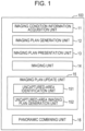
- Fig. 1 is a block configuration diagram of an imaging plan presentation apparatus 100 according to a preferred embodiment of the present invention.
- the imaging plan presentation apparatus 100 includes an imaging condition information acquisition unit 11, an imaging plan generation unit 12, an imaging plan presentation unit 13, an imaging unit 14, an imaging plan update unit 15, and a panoramic combining unit 16.
- a processor includes a CPU (Central Processing Unit), an ASIC (Application Specific Integrated Circuit), a GPU (Graphics Processing Unit), and so on.
- the imaging plan presentation apparatus 100 is constituted by a mobile information terminal such as a smartphone, a tablet terminal, or a digital camera, a personal computer, or the like.
- the imaging unit 14 and/or the panoramic combining unit 16 may or may not be integrated with the imaging plan presentation apparatus 100.
- the imaging condition information acquisition unit 11 acquires imaging condition information from an internal sensor, an external terminal (a smartphone possessed by a user at an inspection site), or the like.
- the imaging condition information includes the conditions of the inspection site, namely, position information of the inspection site, the current time, the weather, the size of the inspection-target structure (photographic subject), and the imaging distance from the photographic subject to the camera, the imaging conditions of the camera, namely, the focal length, the number of pixels, the size of an image sensor of the digital camera, and the required resolution of the photographic subject, and so on.
- the size of the photographic subject is, for example, the size of a panel (the vertical and horizontal sizes of a panel) on a bridge, the height and width of a bridge pier, or the like.
- the imaging distance is the distance from the camera to the photographic subject, examples of which include the distance from the camera to the deck.
- the position information of the inspection site can be acquired by using GPS (Global Positioning System).
- the imaging plan generation unit 12 generates, based on the imaging condition information, an imaging plan including a set of imaging ranges to cover the entirety of each check point for the inspection-target photographic subject. For example, the imaging plan generation unit 12 calculates the actual imaging size of each image satisfying a desired photographic-subject resolution and generates an imaging range covering each check point and having the calculated actual imaging size such that the overlap rate between different images is greater than or equal to a predetermined overlap rate.
- the predetermined overlap rate is assumed to be 30%. More specifically, an imaging plan is generated in which the predetermined overlap rate (such as 30%) is satisfied and the number of captured images is minimum. If no imaging plan satisfying the imaging conditions can be generated, a warning such as "the imaging distance is too long" or "the predetermined photographic-subject resolution is not satisfied with the focal length of the lens to be used" may be displayed on a display of the imaging plan presentation apparatus 100, for example, to notify the user of the warning to prompt the user to reset the imaging condition information.
- the overlap rate can be set as desired so long as the panoramic combining unit 16 can combine individual imaging ranges into a panoramic image.
- the imaging plan includes at least an imaging range and the number of pixels. Since the user can adjust, as desired, the focal length, the imaging distance, and the imaging position to match the imaging range, the imaging plan may or may not include the focal length, the imaging distance, and the imaging position.
- the imaging plan presentation unit 13 presents the imaging range to be captured in the current session to the user.
- Examples of the method of presenting the imaging range include displaying the imaging range on an internal display of the imaging plan presentation apparatus 100, displaying the imaging range on a display of an AR (Augmented Reality) device, and projecting the imaging range onto the photographic subject by using a projector.
- the imaging range may be displayed superimposed on a design drawing or the like of the inspection-target photographic subject.
- the imaging unit 14 is a device constituted by a digital camera or the like and configured to generate and output image data (sub-image) obtained by capturing the imaging range of each check point for the photographic subject, that is, the structure.
- the imaging unit 14 may or may not be contained in the imaging plan presentation apparatus 100.
- the imaging unit 14 may be a digital still camera separate from the imaging plan presentation apparatus 100.
- the imaging unit 14 wirelessly communicates with the imaging plan presentation apparatus 100 and transmits the image data obtained through imaging to the imaging plan presentation apparatus 100.
- the imaging-target structure is not specifically limited, and examples thereof include a deck of a bridge, a road surface, a body concrete surface of a dam, a concrete surface in tunnel lining, and an outer wall of a building.
- the imaging plan update unit 15 includes an uncaptured-area identification unit 151 and an uncaptured-area imaging plan generation unit 152.
- the uncaptured-area identification unit 151 identifies an uncaptured imaging range on the basis of the imaging plan generated by the imaging plan generation unit 12 and the image output from the imaging unit 14.
- the uncaptured-area imaging plan generation unit 152 updates the imaging plan on the basis of the uncaptured imaging range identified by the uncaptured-area identification unit 151 and re-generates an imaging plan corresponding to the uncaptured imaging range.
- the uncaptured-area identification unit 151 converts imaging ranges in a panoramic image obtained by combining sub-images captured in accordance with the imaging plan into the actual size from the actual scale of the photographic subject whose photographic-subject resolution or size in the image are known.
- the uncaptured-area identification unit 151 acquires the measurement value of the actual size of the entire inspection-target photographic subject or actual size information obtained from the drawing, as the actual size of the inspection-target photographic subject.
- the uncaptured-area identification unit 151 compares the actual size of the panoramic image with the actual size of the inspection-target photographic subject and identifies a non-matching portion therebetween as an uncaptured area.
- the uncaptured-area identification unit 151 checks a panoramic image obtained by combining sub-images captured in accordance with the imaging plan against the full view of the photographic subject by using block matching or the like and identifies an area corresponding to the difference therebetween as an uncaptured area.
- the uncaptured-area identification unit 151 acquires imaging condition information (such as imaging position information, the imaging direction, the imaging distance, the focal length, and the size of the image sensor) of an image captured in accordance with the imaging plan. These are imaging condition information corresponding to a captured imaging range. Then, the uncaptured-area identification unit 151 compares the imaging condition information corresponding to the captured imaging range with the imaging condition information of the imaging plan and identifies an uncaptured area from a non-matching portion therebetween.
- imaging condition information such as imaging position information, the imaging direction, the imaging distance, the focal length, and the size of the image sensor
- the imaging plan that is re-generated by the imaging plan update unit 15 is presented to the user again by the imaging plan presentation unit 13.
- the user can continuously capture a required imaging range in accordance with the imaging plan.
- Fig. 3 illustrates an example of an imaging plan.
- the inspection point of the inspection-target photographic subject is a surface R of a deck of a bridge.
- the imaging plan includes imaging ranges R1 to R12 having a predetermined overlap rate D.
- R1 to R12 denote ranges to be captured in order from first to twelfth, respectively, to capture the full view (all the check points) of the inspection-target photographic subject in the shortest imaging order (shortest distance).
- the full view of the photographic subject is captured as a single image in advance by using a full-view image acquisition unit constituted by the imaging unit 14 and so on.
- the imaging resolution for the full view of the photographic subject is arbitrary since fine cracks are not to be detected.
- the moving distance for imaging is the shortest.
- the movement direction of the imaging position may be fixed or priority may be given to the movement order depending on the circumstances. In this case, it is desirable to generate an imaging plan in accordance with a rule for the movement direction, the movement order, or the like.
- Fig. 4 illustrates an example of the presentation of an imaging plan.
- a live view image W of a photographic subject and an imaging range Rk are displayed in a superimposed manner on the imaging plan presentation unit 13 of the imaging plan presentation apparatus 100, which is constituted by a display of a camera-equipped mobile information terminal such as a tablet, a digital camera, or a smartphone.
- the imaging range to be displayed on the imaging plan presentation unit 13, which is constituted by a display may be calculated on the basis of the position information of the camera-equipped mobile information terminal acquired by using GPS (Global Positioning System).
- GPS Global Positioning System
- the imaging range may be displayed superimposed on a live view of a real photographic subject viewed by the user using an AR (Augmented Reality) device such as a head-mounted display.
- AR Augmented Reality
- the imaging plan presentation apparatus 100 acquires a live view image captured by the imaging unit 14, which is constituted by a digital still camera, and performs object recognition using the image.
- the imaging plan presentation apparatus 100 recognizes the inspection target in real time, superimposes the imaging range on the recognized inspection target in the live view image in real time, and displays the live view image on the AR device. Even if an imaging condition such as the imaging position or the imaging angle changes in accordance with a movement of the imaging plan presentation apparatus 100, the imaging range is displayed accordingly.
- an imaging start instruction may be transmitted from the imaging plan presentation apparatus 100 to the imaging unit 14, and the imaging unit 14 may perform imaging in accordance with the instruction. This allows imaging to be automatically performed when an inspection target to be photographed in accordance with the imaging plan is captured in the imaging range, which is convenient.
- the user may be notified of this state through a message such as "imaging OK" that is displayed on a display of an AR device or the like or is reproduced audibly, or through the activation of the vibration function of the mobile phone to prompt the user to start imaging.
- the imaging range X1 and the live view X2 of the inspection target match includes a state where both match completely and a state where X1 and X2 overlap with the shift therebetween being within a predetermined threshold allowable range (for example, the area of the shift portion is within 5% of the area of the imaging range).
- a message such as "imaging NG” may be displayed.
- an image of the imaging range to be captured in the current session may be directly projected onto the inspection-target photographic subject by using a projector.
- the imaging ranges to be captured in the next and subsequent sessions may also be projected together with the imaging order.
- a device capable of measuring the distance and the angle from a reference object, such as a GPS (Global Positioning System) terminal or a total station with a built-in range finder, may be used to guide the user by video or audio toward the imaging position, the imaging angle, and the imaging direction at which the imaging range can be captured. If the imaging direction, the imaging distance, the focal length, and the like of the imaging unit 14 do not vary, the user may be guided only to the imaging position. The camera may be guided to the imaging position by using a device such as a total station.
- a GPS Global Positioning System
- Fig. 7 is a flowchart of an imaging plan presentation process.
- a program for causing various computers (processors) to execute this process is recorded on various computer (processor) readable recording media such as an SDRAM, a ROM, and a CD-ROM.
- the imaging condition information acquisition unit 11 acquires imaging condition information from an internal sensor, an external terminal, or the like.
- the imaging condition information includes the size of a structure, which includes the actual size of check points for the structure, the number of pixels of a captured image, the resolution, and the overlap rate between different images.
- the imaging plan generation unit 12 generates, based on the imaging condition information, an imaging plan including imaging ranges for respective imaging sessions such that the entirety (all the check points) of the inspection-target photographic subject can be covered.
- the imaging plan presentation unit 13 presents, based on the imaging plan, the imaging range to be captured to the user by using a display, audio, vibration, or the like.
- the imaging unit 14 outputs image data (sub-image) obtained by photographing the photographic subject within the imaging range.
- the photographic subject is photographed by the imaging unit 14 when an instruction is input from the user or when the processor determines that a predetermined imaging condition is satisfied (for example, that the imaging range X1 and the live view X2 of the inspection target match).
- the imaging plan update unit 15 determines whether an uncaptured area has been identified by the uncaptured-area identification unit 151 after the imaging unit 14 completes imaging. If Yes is obtained, S6 is performed. If No is obtained, the process ends.
- the imaging plan update unit 15 updates the imaging plan on the basis of the uncaptured imaging range, and re-generates an imaging plan corresponding to the uncaptured imaging range. Then, the process returns to S3, and the imaging plan presentation unit 13 presents, based on the re-generated imaging plan, the imaging range to be captured next to the user.
- the panoramic combining unit 16 may combine sub-images captured in accordance with the imaging plan to create a panoramic image.
- an imaging plan is updated in accordance with an uncaptured area, and an imaging range to be captured next is presented to a user. This allows the user to easily capture an uncaptured portion.
- the inspection-target photographic subject can be photographed for all the required ranges.
- the imaging time can be minimized.
Landscapes
- Engineering & Computer Science (AREA)
- Multimedia (AREA)
- Signal Processing (AREA)
- Physics & Mathematics (AREA)
- General Physics & Mathematics (AREA)
- Human Computer Interaction (AREA)
- Studio Devices (AREA)
- Stereoscopic And Panoramic Photography (AREA)
- Indication In Cameras, And Counting Of Exposures (AREA)
- Closed-Circuit Television Systems (AREA)
Claims (15)
- Appareil de présentation de plan d'imagerie (100), comprenant :
une unité d'acquisition de condition d'imagerie (11), laquelle est configurée pour acquérir une condition d'imagerie nécessaire pour la détection d'endommagement d'une structure :une unité de génération de plan d'imagerie (12), laquelle est configurée pour générer un plan d'imagerie incluant un jeu de plages d'imagerie pour couvrir une entièreté de chaque point de vérification pour la structure sur la base de la condition d'imagerie acquise par l'unité d'acquisition de condition d'imagerie ;une unité de présentation de plan d'imagerie (13), laquelle est configurée pour présenter le plan d'imagerie à un utilisateur, dans lequel l'appareil de présentation de plan d'imagerie est caractérisé en ce qu'il comprend en outre :une unité de mise à jour de plan d'imagerie (15), laquelle est configurée pour mettre à jour le plan d'imagerie sur la base d'une plage d'imagerie non capturée identifiée sur la base du plan d'imagerie généré par l'unité de génération de plan d'imagerie (12) et de données d'image obtenues en capturant la plage d'imagerie de chaque point de vérification pour la structure, et pour regénérer un plan d'imagerie correspondant à la plage d'imagerie non capturée,dans lequel l'unité de présentation de plan d'imagerie (13) est configurée pour présenter le plan d'imagerie regénéré par l'unité de mise à jour de plan d'imagerie (15) à l'utilisateur. - Appareil de présentation de plan d'imagerie (100) selon la revendication 1.
dans lequel l'unité de présentation de plan d'imagerie (13) est configurée pour présenter, à l'utilisateur, une plage d'imagerie à capturer ensuite, sur la base du plan d'imagerie regénéré par l'unité de mise à jour de plan d'imagerie (15). - Appareil de présentation de plan d'imagerie (100) selon la revendication 1 ou 2.
dans lequel l'unité de génération de plan d'imagerie génère un plan d'imagerie de telle sorte qu'un chevauchement entre différentes images est supérieur ou égal à un taux de chevauchement prédéterminé et qu'un nombre d'images capturées pour couvrir l'entièreté du point de vérification pour la structure est minimal, sur la base d'une taille d'imagerie réelle de chaque image satisfaisant une résolution de sujet photographique souhaitée. - Appareil de présentation de plan d'imagerie (100) selon l'une quelconque des revendications 1 à 3,
dans lequel l'unité de génération de plan d'imagerie (12) est configurée pour générer un plan d'imagerie de telle sorte qu'une distance de déplacement d'un dispositif d'imagerie pour réaliser une imagerie pour couvrir l'entièreté des points de vérification pour la structure est la plus courte. - Appareil de présentation de plan d'imagerie (100) selon l'une quelconque des revendications 1 à 4,
dans lequel la condition d'imagerie inclut une taille de la structure, le nombre de pixels d'une image capturée, une résolution, et un taux de chevauchement entre différentes d'images. - Appareil de présentation de plan d'imagerie (100) selon la revendication 5.dans lequel le plan d'imagerie est une plage d'imagerie correspondant à des sous-zones obtenues en divisant une surface des points de vérification pour la structure en une pluralité de zones, etdans lequel l'unité de génération de plan d'imagerie (12) est configurée pour calculer une taille d'imagerie réelle de chaque image capturée à partir de la résolution et du nombre de pixels, et générer, comme plan d'imagerie, une plage d'imagerie, laquelle couvre la surface de chaque point de vérification pour la structure au taux de chevauchement ou davantage.
- Appareil de présentation de plan d'imagerie (100) selon la revendication 6.dans lequel le plan d'imagerie inclut un ordre d'imagerie des sous-zones, etdans lequel l'unité de génération de plan d'imagerie (12) est configurée pour générer un plan d'imagerie de telle sorte qu'une distance de déplacement d'un dispositif d'imagerie pour réaliser une imagerie dans l'ordre d'imagerie est la plus courte.
- Appareil de présentation de plan d'imagerie (100) selon la revendication 6 ou 7,dans lequel l'unité de présentation de plan d'imagerie (13) est configurée pour présenter la plage d'imagerie de telle sorte que la plage d'imagerie est superposée sur un dessin de la structure, oul'unité de présentation de plan d'imagerie (13) est configurée pour présenter la plage d'imagerie de telle sorte que la plage d'imagerie est superposée sur un dessin de la structure affichée sur un affichage, oul'unité de présentation de plan d'imagerie (13) est configurée pour présenter la plage d'imagerie de telle sorte que la plage d'imagerie est superposée sur les points de vérification pour la structure en utilisant un projecteur, oul'unité de présentation de plan d'imagerie (13) est configurée pour présenter la plage d'imagerie de telle sorte que la plage d'imagerie est superposée sur une image capturée des points de vérification pour la structure à l'aide d'un dispositif de réalité augmentée.
- Appareil de présentation de plan d'imagerie (100) selon la revendication 6 ou 7.
dans lequel l'unité de présentation de plan d'imagerie (13) inclut une unité de guidage d'utilisateur, laquelle est configurée pour guider l'utilisateur vers une position d'imagerie sur la base des informations de position d'un dispositif d'imagerie ou d'informations de mesure de distance du dispositif d'imagerie vers la structure. - Appareil de présentation de plan d'imagerie (100) selon l'une quelconque des revendications 1 à 9, comprenant en outre :une unité d'acquisition de taille réelle, laquelle est configurée pour acquérir une taille réelle des points de vérification pour la structure, etune unité de création d'image panoramique, laquelle est configurée pour combiner une pluralité d'images capturées des points de vérification pour la structure afin de créer une image panoramique,dans lequel l'unité de génération de plan d'imagerie (12) est configurée pour identifier une zone non capturée sur la base de la taille réelle des points de vérification pour la structure acquise par l'unité d'acquisition de taille réelle et de l'image panoramique créée par l'unité de création d'image panoramique, et régénère un plan d'imagerie correspondant à la zone non capturée identifiée.
- Appareil de présentation de plan d'imagerie (100) selon l'une quelconque des revendications 1 à 10, comprenant en outre :une unité d'acquisition d'image de vue complète, laquelle est configurée pour acquérir une image de vue complète des points de vérification pour la structure, etune unité d'acquisition de sous-image, laquelle est configurée pour acquérir une pluralité de sous-images, chacune étant une image capturée d'une portion des points de vérification pour la structure,dans lequel l'unité de génération de plan d'imagerie (12) est configurée pour vérifier la pluralité de sous-images par rapport à l'image de vue complète afin d'identifier une zone non capturée, et de regénérer un plan d'imagerie correspondant à la zone non capturée identifiée.
- Appareil de présentation de plan d'imagerie (100) selon l'une quelconque des revendications 1 à 10, comprenant en outreune unité d'acquisition de condition d'imagerie réelle, laquelle est configurée pour acquérir une condition d'imagerie réelle incluant au moins un élément parmi une position d'imagerie d'une image réellement capturée des points de vérification pour la structure, une direction d'imagerie, une distance d'imagerie, une longueur focale, ou une taille de capteur.dans lequel l'unité de génération de plan d'imagerie est configurée pour identifier une zone non capturée sur la base de la condition d'imagerie réelle, et de regénérer un plan d'imagerie correspondant à la zone non capturée identifiée.
- Procédé de présentation de plan d'imagerie réalisé par un ordinateur, comprenant les étapes consistant à :
acquérir (S1) une condition d'imagerie nécessaire pour la détection d'endommagement d'une structure :générer (S2) un plan d'imagerie incluant un jeu de plages d'imagerie pour couvrir une entièreté de chaque point de vérification pour la structure sur la base de la condition d'imagerie ;présenter (S3) le plan d'imagerie à un utilisateur,dans lequel le procédé de présentation de plan d'imagerie est caractérisé en ce qu'il comprend en outre des étapes pour :mettre à jour (S6) le plan d'imagerie sur la base d'une plage d'imagerie non capturée identifiée sur la base du plan d'imagerie et de données d'image obtenues en capturant la plage d'imagerie de chaque point de vérification pour la structure, et pour regénérer un plan d'imagerie correspondant à la plage d'imagerie non capturée, etprésenter (S3) le plan d'imagerie à l'utilisateur. - Procédé de présentation de plan d'imagerie selon la revendication 13,
dans lequel l'étape pour présenter (S3) le plan d'imagerie regénéré à l'utilisateur inclut une étape pour présenter une plage d'imagerie à capturer ensuite à l'utilisateur sur la base du plan d'imagerie regénéré. - Support d'enregistrement lisible par ordinateur non transitoire faisant en sorte qu'un ordinateur réalise le procédé de présentation de plan d'imagerie selon la revendication 13 ou 14 lorsque des instructions stockées dans le support d'enregistrement sont lues par l' ordinateur.
Applications Claiming Priority (2)
| Application Number | Priority Date | Filing Date | Title |
|---|---|---|---|
| JP2018126941 | 2018-07-03 | ||
| PCT/JP2019/025340 WO2020008973A1 (fr) | 2018-07-03 | 2019-06-26 | Dispositif et procédé de présentation de plan de capture d'image |
Publications (3)
| Publication Number | Publication Date |
|---|---|
| EP3820139A1 EP3820139A1 (fr) | 2021-05-12 |
| EP3820139A4 EP3820139A4 (fr) | 2021-08-25 |
| EP3820139B1 true EP3820139B1 (fr) | 2023-09-13 |
Family
ID=69059604
Family Applications (1)
| Application Number | Title | Priority Date | Filing Date |
|---|---|---|---|
| EP19830411.5A Active EP3820139B1 (fr) | 2018-07-03 | 2019-06-26 | Dispositif et procédé de présentation de plan de capture d'image |
Country Status (5)
| Country | Link |
|---|---|
| US (2) | US11528411B2 (fr) |
| EP (1) | EP3820139B1 (fr) |
| JP (1) | JP6965450B2 (fr) |
| CN (1) | CN112385207B (fr) |
| WO (1) | WO2020008973A1 (fr) |
Families Citing this family (6)
| Publication number | Priority date | Publication date | Assignee | Title |
|---|---|---|---|---|
| JP7050824B2 (ja) * | 2018-02-02 | 2022-04-08 | 富士フイルム株式会社 | 画像処理装置及び画像処理方法 |
| CN112887619A (zh) * | 2021-01-28 | 2021-06-01 | 维沃移动通信有限公司 | 拍摄方法、装置及电子设备 |
| WO2022202429A1 (fr) * | 2021-03-23 | 2022-09-29 | 富士フイルム株式会社 | Dispositif de traitement d'informations, procédé de traitement d'informations, programme, et système de traitement d'informations |
| WO2022249864A1 (fr) * | 2021-05-24 | 2022-12-01 | 富士フイルム株式会社 | Dispositif d'assistance à l'imagerie, système d'imagerie, procédé d'assistance à l'imagerie et programme |
| JP2023093044A (ja) | 2021-12-22 | 2023-07-04 | キヤノン株式会社 | 情報処理装置、撮影システム、方法、及びプログラム |
| DE112022006206T5 (de) | 2021-12-28 | 2024-11-07 | Fujifilm Corporation | Bildgebungsunterstützungsvorrichtung, Bildgebungsunterstützungsverfahren und Programm |
Family Cites Families (18)
| Publication number | Priority date | Publication date | Assignee | Title |
|---|---|---|---|---|
| JPS59158483A (ja) | 1983-02-28 | 1984-09-07 | Toshiba Corp | 文字読取方法 |
| US7418320B1 (en) * | 2005-01-24 | 2008-08-26 | International Business Machines Corporation | Navigating a UAV having an on-board digital camera to capture desired geographic area |
| US20070129626A1 (en) * | 2005-11-23 | 2007-06-07 | Prakash Mahesh | Methods and systems for facilitating surgical procedures |
| JP4715913B2 (ja) * | 2008-12-17 | 2011-07-06 | ソニー株式会社 | 撮像装置、画像処理装置、ズーム制御方法およびズーム制御プログラム |
| CN101815171B (zh) * | 2009-02-24 | 2011-11-23 | 华晶科技股份有限公司 | 图像撷取装置及其自动指示拍摄位置的方法 |
| JP5268025B2 (ja) | 2009-02-27 | 2013-08-21 | 株式会社リコー | 撮影装置 |
| KR101586071B1 (ko) * | 2012-08-29 | 2016-02-03 | 한국과학기술연구원 | 마커리스 증강현실 서비스 제공 장치 및 이를 위한 촬영 위치 추정 방법 |
| KR102246645B1 (ko) * | 2013-07-15 | 2021-04-30 | 삼성전자주식회사 | 영상 획득을 위한 장치 및 방법 |
| US9955068B2 (en) * | 2013-07-15 | 2018-04-24 | Samsung Electronics Co., Ltd. | Apparatus and method for operating a composition of a picture in a portable terminal |
| CN104243814B (zh) * | 2014-07-28 | 2018-02-02 | 小米科技有限责任公司 | 图像中物体布局的分析方法、图像拍摄提示方法及装置 |
| JP2017071972A (ja) | 2015-10-08 | 2017-04-13 | 株式会社ニコン | 点検支援方法および点検支援システム |
| JP6576474B2 (ja) * | 2016-01-26 | 2019-09-18 | 富士フイルム株式会社 | 撮影支援装置及び撮影支援方法 |
| JP6835536B2 (ja) * | 2016-03-09 | 2021-02-24 | 株式会社リコー | 画像処理方法、表示装置および点検システム |
| WO2017155005A1 (fr) * | 2016-03-09 | 2017-09-14 | Ricoh Company, Ltd. | Procédé de traitement d'image, dispositif d'affichage et système d'inspection |
| JP6120037B1 (ja) * | 2016-11-30 | 2017-04-26 | 国際航業株式会社 | 点検装置、及び点検方法 |
| JP6619761B2 (ja) * | 2017-03-13 | 2019-12-11 | ヤンマー株式会社 | 無人飛行撮影装置 |
| GB201709199D0 (en) * | 2017-06-09 | 2017-07-26 | Delamont Dean Lindsay | IR mixed reality and augmented reality gaming system |
| WO2019041276A1 (fr) * | 2017-08-31 | 2019-03-07 | 深圳市大疆创新科技有限公司 | Procédé de traitement d'image, véhicule aérien sans pilote et système |
-
2019
- 2019-06-26 JP JP2020528818A patent/JP6965450B2/ja active Active
- 2019-06-26 EP EP19830411.5A patent/EP3820139B1/fr active Active
- 2019-06-26 CN CN201980042874.4A patent/CN112385207B/zh active Active
- 2019-06-26 WO PCT/JP2019/025340 patent/WO2020008973A1/fr not_active Ceased
-
2020
- 2020-12-08 US US17/115,188 patent/US11528411B2/en active Active
-
2022
- 2022-11-10 US US18/054,476 patent/US11895396B2/en active Active
Also Published As
| Publication number | Publication date |
|---|---|
| US11895396B2 (en) | 2024-02-06 |
| JPWO2020008973A1 (ja) | 2021-09-09 |
| JP6965450B2 (ja) | 2021-11-10 |
| US11528411B2 (en) | 2022-12-13 |
| EP3820139A1 (fr) | 2021-05-12 |
| US20230072448A1 (en) | 2023-03-09 |
| WO2020008973A1 (fr) | 2020-01-09 |
| US20210092288A1 (en) | 2021-03-25 |
| EP3820139A4 (fr) | 2021-08-25 |
| CN112385207B (zh) | 2022-04-12 |
| CN112385207A (zh) | 2021-02-19 |
Similar Documents
| Publication | Publication Date | Title |
|---|---|---|
| US11895396B2 (en) | Imaging plan presentation apparatus and method for updating and re-generating an imaging plan | |
| KR102111935B1 (ko) | 표시 제어장치, 표시 제어방법 및 프로그램 | |
| US8482599B2 (en) | 3D modeling apparatus, 3D modeling method, and computer readable medium | |
| JP6594180B2 (ja) | 撮像装置、撮像装置の制御方法及びプログラム | |
| JP6070206B2 (ja) | 位置座標変換システム、位置座標変換方法、車載装置、世界座標計測装置および位置座標変換プログラム | |
| US9413952B2 (en) | Image processing apparatus, distance measuring apparatus, imaging apparatus, and image processing method | |
| US8428341B2 (en) | Apparatus for calculating 3D spatial coordinates of digital images and method thereof | |
| JP6656035B2 (ja) | 画像処理装置、撮像装置および画像処理装置の制御方法 | |
| JP2018036117A (ja) | 距離計測装置、撮像制御装置 | |
| CN114009005A (zh) | 红外图像处理方法、电子设备及计算机可读存储介质 | |
| JP4871315B2 (ja) | 複眼撮影装置およびその制御方法並びにプログラム | |
| JP4198536B2 (ja) | 物体撮影装置、物体撮影方法及び物体撮影プログラム | |
| CN118435617A (zh) | 摄像辅助装置、摄像辅助方法及程序 | |
| EP2106129A2 (fr) | Appareil photographique d'oeil composé, son procédé de contrôle et programme | |
| JP6672082B2 (ja) | 撮像装置、撮像方法およびプログラム | |
| JP6257798B2 (ja) | 画像処理装置及び画像処理方法 | |
| JP5137219B2 (ja) | 複眼撮影装置およびその制御方法並びにプログラム | |
| JP2012165212A (ja) | 撮像装置及びその制御方法 | |
| JP7211502B2 (ja) | 撮像装置、撮像方法及びプログラム | |
| JP6234200B2 (ja) | 画像処理装置、画像処理方法およびプログラム | |
| JP2022155133A (ja) | 画像処理装置、画像処理装置の制御方法 | |
| JP2019082375A (ja) | カメラ装置及び距離測定方法 | |
| JP2018033039A (ja) | 画像補正装置および画像補正方法 | |
| JP2015032948A (ja) | 画像処理装置、その制御方法、および制御プログラム |
Legal Events
| Date | Code | Title | Description |
|---|---|---|---|
| STAA | Information on the status of an ep patent application or granted ep patent |
Free format text: STATUS: THE INTERNATIONAL PUBLICATION HAS BEEN MADE |
|
| PUAI | Public reference made under article 153(3) epc to a published international application that has entered the european phase |
Free format text: ORIGINAL CODE: 0009012 |
|
| STAA | Information on the status of an ep patent application or granted ep patent |
Free format text: STATUS: REQUEST FOR EXAMINATION WAS MADE |
|
| 17P | Request for examination filed |
Effective date: 20201222 |
|
| AK | Designated contracting states |
Kind code of ref document: A1 Designated state(s): AL AT BE BG CH CY CZ DE DK EE ES FI FR GB GR HR HU IE IS IT LI LT LU LV MC MK MT NL NO PL PT RO RS SE SI SK SM TR |
|
| A4 | Supplementary search report drawn up and despatched |
Effective date: 20210723 |
|
| RIC1 | Information provided on ipc code assigned before grant |
Ipc: H04N 5/232 20060101AFI20210719BHEP Ipc: G03B 15/00 20210101ALI20210719BHEP Ipc: G03B 37/00 20210101ALI20210719BHEP |
|
| DAV | Request for validation of the european patent (deleted) | ||
| DAX | Request for extension of the european patent (deleted) | ||
| REG | Reference to a national code |
Ref country code: DE Ref country code: DE Ref legal event code: R079 Ref document number: 602019037535 Country of ref document: DE Free format text: PREVIOUS MAIN CLASS: H04N0005232000 Ipc: H04N0005600000 |
|
| REG | Reference to a national code |
Ref country code: DE Ref legal event code: R079 Free format text: PREVIOUS MAIN CLASS: H04N0005600000 Ipc: H04N0023600000 Ref document number: 602019037535 Country of ref document: DE |
|
| GRAP | Despatch of communication of intention to grant a patent |
Free format text: ORIGINAL CODE: EPIDOSNIGR1 |
|
| STAA | Information on the status of an ep patent application or granted ep patent |
Free format text: STATUS: GRANT OF PATENT IS INTENDED |
|
| RIC1 | Information provided on ipc code assigned before grant |
Ipc: H04N 23/698 20230101ALI20230220BHEP Ipc: H04N 5/63 20060101ALI20230220BHEP Ipc: H04N 5/60 20060101AFI20230220BHEP |
|
| RIC1 | Information provided on ipc code assigned before grant |
Ipc: H04N 5/63 20060101ALI20230308BHEP Ipc: H04N 5/60 20060101ALI20230308BHEP Ipc: H04N 23/698 20230101ALI20230308BHEP Ipc: H04N 23/63 20230101ALI20230308BHEP Ipc: H04N 23/60 20230101AFI20230308BHEP |
|
| INTG | Intention to grant announced |
Effective date: 20230320 |
|
| P01 | Opt-out of the competence of the unified patent court (upc) registered |
Effective date: 20230515 |
|
| GRAS | Grant fee paid |
Free format text: ORIGINAL CODE: EPIDOSNIGR3 |
|
| GRAA | (expected) grant |
Free format text: ORIGINAL CODE: 0009210 |
|
| STAA | Information on the status of an ep patent application or granted ep patent |
Free format text: STATUS: THE PATENT HAS BEEN GRANTED |
|
| AK | Designated contracting states |
Kind code of ref document: B1 Designated state(s): AL AT BE BG CH CY CZ DE DK EE ES FI FR GB GR HR HU IE IS IT LI LT LU LV MC MK MT NL NO PL PT RO RS SE SI SK SM TR |
|
| REG | Reference to a national code |
Ref country code: CH Ref legal event code: EP |
|
| REG | Reference to a national code |
Ref country code: DE Ref legal event code: R096 Ref document number: 602019037535 Country of ref document: DE |
|
| REG | Reference to a national code |
Ref country code: IE Ref legal event code: FG4D |
|
| REG | Reference to a national code |
Ref country code: LT Ref legal event code: MG9D |
|
| REG | Reference to a national code |
Ref country code: NL Ref legal event code: MP Effective date: 20230913 |
|
| PG25 | Lapsed in a contracting state [announced via postgrant information from national office to epo] |
Ref country code: GR Free format text: LAPSE BECAUSE OF FAILURE TO SUBMIT A TRANSLATION OF THE DESCRIPTION OR TO PAY THE FEE WITHIN THE PRESCRIBED TIME-LIMIT Effective date: 20231214 |
|
| PG25 | Lapsed in a contracting state [announced via postgrant information from national office to epo] |
Ref country code: SE Free format text: LAPSE BECAUSE OF FAILURE TO SUBMIT A TRANSLATION OF THE DESCRIPTION OR TO PAY THE FEE WITHIN THE PRESCRIBED TIME-LIMIT Effective date: 20230913 Ref country code: RS Free format text: LAPSE BECAUSE OF FAILURE TO SUBMIT A TRANSLATION OF THE DESCRIPTION OR TO PAY THE FEE WITHIN THE PRESCRIBED TIME-LIMIT Effective date: 20230913 Ref country code: NO Free format text: LAPSE BECAUSE OF FAILURE TO SUBMIT A TRANSLATION OF THE DESCRIPTION OR TO PAY THE FEE WITHIN THE PRESCRIBED TIME-LIMIT Effective date: 20231213 Ref country code: LV Free format text: LAPSE BECAUSE OF FAILURE TO SUBMIT A TRANSLATION OF THE DESCRIPTION OR TO PAY THE FEE WITHIN THE PRESCRIBED TIME-LIMIT Effective date: 20230913 Ref country code: LT Free format text: LAPSE BECAUSE OF FAILURE TO SUBMIT A TRANSLATION OF THE DESCRIPTION OR TO PAY THE FEE WITHIN THE PRESCRIBED TIME-LIMIT Effective date: 20230913 Ref country code: HR Free format text: LAPSE BECAUSE OF FAILURE TO SUBMIT A TRANSLATION OF THE DESCRIPTION OR TO PAY THE FEE WITHIN THE PRESCRIBED TIME-LIMIT Effective date: 20230913 Ref country code: GR Free format text: LAPSE BECAUSE OF FAILURE TO SUBMIT A TRANSLATION OF THE DESCRIPTION OR TO PAY THE FEE WITHIN THE PRESCRIBED TIME-LIMIT Effective date: 20231214 Ref country code: FI Free format text: LAPSE BECAUSE OF FAILURE TO SUBMIT A TRANSLATION OF THE DESCRIPTION OR TO PAY THE FEE WITHIN THE PRESCRIBED TIME-LIMIT Effective date: 20230913 |
|
| REG | Reference to a national code |
Ref country code: AT Ref legal event code: MK05 Ref document number: 1612487 Country of ref document: AT Kind code of ref document: T Effective date: 20230913 |
|
| PG25 | Lapsed in a contracting state [announced via postgrant information from national office to epo] |
Ref country code: NL Free format text: LAPSE BECAUSE OF FAILURE TO SUBMIT A TRANSLATION OF THE DESCRIPTION OR TO PAY THE FEE WITHIN THE PRESCRIBED TIME-LIMIT Effective date: 20230913 |
|
| PG25 | Lapsed in a contracting state [announced via postgrant information from national office to epo] |
Ref country code: IS Free format text: LAPSE BECAUSE OF FAILURE TO SUBMIT A TRANSLATION OF THE DESCRIPTION OR TO PAY THE FEE WITHIN THE PRESCRIBED TIME-LIMIT Effective date: 20240113 |
|
| PG25 | Lapsed in a contracting state [announced via postgrant information from national office to epo] |
Ref country code: AT Free format text: LAPSE BECAUSE OF FAILURE TO SUBMIT A TRANSLATION OF THE DESCRIPTION OR TO PAY THE FEE WITHIN THE PRESCRIBED TIME-LIMIT Effective date: 20230913 |
|
| PG25 | Lapsed in a contracting state [announced via postgrant information from national office to epo] |
Ref country code: ES Free format text: LAPSE BECAUSE OF FAILURE TO SUBMIT A TRANSLATION OF THE DESCRIPTION OR TO PAY THE FEE WITHIN THE PRESCRIBED TIME-LIMIT Effective date: 20230913 |
|
| PG25 | Lapsed in a contracting state [announced via postgrant information from national office to epo] |
Ref country code: SM Free format text: LAPSE BECAUSE OF FAILURE TO SUBMIT A TRANSLATION OF THE DESCRIPTION OR TO PAY THE FEE WITHIN THE PRESCRIBED TIME-LIMIT Effective date: 20230913 Ref country code: RO Free format text: LAPSE BECAUSE OF FAILURE TO SUBMIT A TRANSLATION OF THE DESCRIPTION OR TO PAY THE FEE WITHIN THE PRESCRIBED TIME-LIMIT Effective date: 20230913 Ref country code: IS Free format text: LAPSE BECAUSE OF FAILURE TO SUBMIT A TRANSLATION OF THE DESCRIPTION OR TO PAY THE FEE WITHIN THE PRESCRIBED TIME-LIMIT Effective date: 20240113 Ref country code: ES Free format text: LAPSE BECAUSE OF FAILURE TO SUBMIT A TRANSLATION OF THE DESCRIPTION OR TO PAY THE FEE WITHIN THE PRESCRIBED TIME-LIMIT Effective date: 20230913 Ref country code: EE Free format text: LAPSE BECAUSE OF FAILURE TO SUBMIT A TRANSLATION OF THE DESCRIPTION OR TO PAY THE FEE WITHIN THE PRESCRIBED TIME-LIMIT Effective date: 20230913 Ref country code: CZ Free format text: LAPSE BECAUSE OF FAILURE TO SUBMIT A TRANSLATION OF THE DESCRIPTION OR TO PAY THE FEE WITHIN THE PRESCRIBED TIME-LIMIT Effective date: 20230913 Ref country code: AT Free format text: LAPSE BECAUSE OF FAILURE TO SUBMIT A TRANSLATION OF THE DESCRIPTION OR TO PAY THE FEE WITHIN THE PRESCRIBED TIME-LIMIT Effective date: 20230913 Ref country code: SK Free format text: LAPSE BECAUSE OF FAILURE TO SUBMIT A TRANSLATION OF THE DESCRIPTION OR TO PAY THE FEE WITHIN THE PRESCRIBED TIME-LIMIT Effective date: 20230913 Ref country code: PT Free format text: LAPSE BECAUSE OF FAILURE TO SUBMIT A TRANSLATION OF THE DESCRIPTION OR TO PAY THE FEE WITHIN THE PRESCRIBED TIME-LIMIT Effective date: 20240115 |
|
| PG25 | Lapsed in a contracting state [announced via postgrant information from national office to epo] |
Ref country code: PL Free format text: LAPSE BECAUSE OF FAILURE TO SUBMIT A TRANSLATION OF THE DESCRIPTION OR TO PAY THE FEE WITHIN THE PRESCRIBED TIME-LIMIT Effective date: 20230913 Ref country code: IT Free format text: LAPSE BECAUSE OF FAILURE TO SUBMIT A TRANSLATION OF THE DESCRIPTION OR TO PAY THE FEE WITHIN THE PRESCRIBED TIME-LIMIT Effective date: 20230913 |
|
| REG | Reference to a national code |
Ref country code: DE Ref legal event code: R097 Ref document number: 602019037535 Country of ref document: DE |
|
| PG25 | Lapsed in a contracting state [announced via postgrant information from national office to epo] |
Ref country code: DK Free format text: LAPSE BECAUSE OF FAILURE TO SUBMIT A TRANSLATION OF THE DESCRIPTION OR TO PAY THE FEE WITHIN THE PRESCRIBED TIME-LIMIT Effective date: 20230913 |
|
| PLBE | No opposition filed within time limit |
Free format text: ORIGINAL CODE: 0009261 |
|
| STAA | Information on the status of an ep patent application or granted ep patent |
Free format text: STATUS: NO OPPOSITION FILED WITHIN TIME LIMIT |
|
| PG25 | Lapsed in a contracting state [announced via postgrant information from national office to epo] |
Ref country code: DK Free format text: LAPSE BECAUSE OF FAILURE TO SUBMIT A TRANSLATION OF THE DESCRIPTION OR TO PAY THE FEE WITHIN THE PRESCRIBED TIME-LIMIT Effective date: 20230913 |
|
| 26N | No opposition filed |
Effective date: 20240614 |
|
| PG25 | Lapsed in a contracting state [announced via postgrant information from national office to epo] |
Ref country code: SI Free format text: LAPSE BECAUSE OF FAILURE TO SUBMIT A TRANSLATION OF THE DESCRIPTION OR TO PAY THE FEE WITHIN THE PRESCRIBED TIME-LIMIT Effective date: 20230913 |
|
| PG25 | Lapsed in a contracting state [announced via postgrant information from national office to epo] |
Ref country code: SI Free format text: LAPSE BECAUSE OF FAILURE TO SUBMIT A TRANSLATION OF THE DESCRIPTION OR TO PAY THE FEE WITHIN THE PRESCRIBED TIME-LIMIT Effective date: 20230913 |
|
| PG25 | Lapsed in a contracting state [announced via postgrant information from national office to epo] |
Ref country code: BG Free format text: LAPSE BECAUSE OF FAILURE TO SUBMIT A TRANSLATION OF THE DESCRIPTION OR TO PAY THE FEE WITHIN THE PRESCRIBED TIME-LIMIT Effective date: 20230913 |
|
| PG25 | Lapsed in a contracting state [announced via postgrant information from national office to epo] |
Ref country code: BG Free format text: LAPSE BECAUSE OF FAILURE TO SUBMIT A TRANSLATION OF THE DESCRIPTION OR TO PAY THE FEE WITHIN THE PRESCRIBED TIME-LIMIT Effective date: 20230913 |
|
| PG25 | Lapsed in a contracting state [announced via postgrant information from national office to epo] |
Ref country code: MC Free format text: LAPSE BECAUSE OF FAILURE TO SUBMIT A TRANSLATION OF THE DESCRIPTION OR TO PAY THE FEE WITHIN THE PRESCRIBED TIME-LIMIT Effective date: 20230913 |
|
| REG | Reference to a national code |
Ref country code: CH Ref legal event code: PL |
|
| PG25 | Lapsed in a contracting state [announced via postgrant information from national office to epo] |
Ref country code: LU Free format text: LAPSE BECAUSE OF NON-PAYMENT OF DUE FEES Effective date: 20240626 |
|
| PG25 | Lapsed in a contracting state [announced via postgrant information from national office to epo] |
Ref country code: IE Free format text: LAPSE BECAUSE OF NON-PAYMENT OF DUE FEES Effective date: 20240626 |
|
| PG25 | Lapsed in a contracting state [announced via postgrant information from national office to epo] |
Ref country code: BE Free format text: LAPSE BECAUSE OF NON-PAYMENT OF DUE FEES Effective date: 20240630 Ref country code: CH Free format text: LAPSE BECAUSE OF NON-PAYMENT OF DUE FEES Effective date: 20240630 |
|
| REG | Reference to a national code |
Ref country code: BE Ref legal event code: MM Effective date: 20240630 |
|
| PGFP | Annual fee paid to national office [announced via postgrant information from national office to epo] |
Ref country code: DE Payment date: 20250429 Year of fee payment: 7 |
|
| PGFP | Annual fee paid to national office [announced via postgrant information from national office to epo] |
Ref country code: GB Payment date: 20250508 Year of fee payment: 7 |
|
| PGFP | Annual fee paid to national office [announced via postgrant information from national office to epo] |
Ref country code: FR Payment date: 20250508 Year of fee payment: 7 |
|
| PG25 | Lapsed in a contracting state [announced via postgrant information from national office to epo] |
Ref country code: CY Free format text: LAPSE BECAUSE OF FAILURE TO SUBMIT A TRANSLATION OF THE DESCRIPTION OR TO PAY THE FEE WITHIN THE PRESCRIBED TIME-LIMIT; INVALID AB INITIO Effective date: 20190626 |
|
| PG25 | Lapsed in a contracting state [announced via postgrant information from national office to epo] |
Ref country code: HU Free format text: LAPSE BECAUSE OF FAILURE TO SUBMIT A TRANSLATION OF THE DESCRIPTION OR TO PAY THE FEE WITHIN THE PRESCRIBED TIME-LIMIT; INVALID AB INITIO Effective date: 20190626 |