EP3820159B1 - Hautparleur - Google Patents
Hautparleur Download PDFInfo
- Publication number
- EP3820159B1 EP3820159B1 EP20204192.7A EP20204192A EP3820159B1 EP 3820159 B1 EP3820159 B1 EP 3820159B1 EP 20204192 A EP20204192 A EP 20204192A EP 3820159 B1 EP3820159 B1 EP 3820159B1
- Authority
- EP
- European Patent Office
- Prior art keywords
- speaker
- resonance
- opening
- frequency range
- acoustic
- Prior art date
- Legal status (The legal status is an assumption and is not a legal conclusion. Google has not performed a legal analysis and makes no representation as to the accuracy of the status listed.)
- Active
Links
Images

Classifications
-
- H—ELECTRICITY
- H04—ELECTRIC COMMUNICATION TECHNIQUE
- H04R—LOUDSPEAKERS, MICROPHONES, GRAMOPHONE PICK-UPS OR LIKE ACOUSTIC ELECTROMECHANICAL TRANSDUCERS; ELECTRIC HEARING AIDS; PUBLIC ADDRESS SYSTEMS
- H04R1/00—Details of transducers, loudspeakers or microphones
- H04R1/20—Arrangements for obtaining desired frequency or directional characteristics
- H04R1/22—Arrangements for obtaining desired frequency or directional characteristics for obtaining desired frequency characteristic only
- H04R1/26—Spatial arrangements of separate transducers responsive to two or more frequency ranges
-
- H—ELECTRICITY
- H04—ELECTRIC COMMUNICATION TECHNIQUE
- H04R—LOUDSPEAKERS, MICROPHONES, GRAMOPHONE PICK-UPS OR LIKE ACOUSTIC ELECTROMECHANICAL TRANSDUCERS; ELECTRIC HEARING AIDS; PUBLIC ADDRESS SYSTEMS
- H04R1/00—Details of transducers, loudspeakers or microphones
- H04R1/20—Arrangements for obtaining desired frequency or directional characteristics
- H04R1/22—Arrangements for obtaining desired frequency or directional characteristics for obtaining desired frequency characteristic only
- H04R1/28—Transducer mountings or enclosures modified by provision of mechanical or acoustic impedances, e.g. resonator, damping means
- H04R1/2869—Reduction of undesired resonances, i.e. standing waves within enclosure, or of undesired vibrations, i.e. of the enclosure itself
- H04R1/2884—Reduction of undesired resonances, i.e. standing waves within enclosure, or of undesired vibrations, i.e. of the enclosure itself by means of the enclosure structure, i.e. strengthening or shape of the enclosure
- H04R1/2888—Reduction of undesired resonances, i.e. standing waves within enclosure, or of undesired vibrations, i.e. of the enclosure itself by means of the enclosure structure, i.e. strengthening or shape of the enclosure for loudspeaker transducers
-
- H—ELECTRICITY
- H04—ELECTRIC COMMUNICATION TECHNIQUE
- H04R—LOUDSPEAKERS, MICROPHONES, GRAMOPHONE PICK-UPS OR LIKE ACOUSTIC ELECTROMECHANICAL TRANSDUCERS; ELECTRIC HEARING AIDS; PUBLIC ADDRESS SYSTEMS
- H04R1/00—Details of transducers, loudspeakers or microphones
- H04R1/20—Arrangements for obtaining desired frequency or directional characteristics
- H04R1/22—Arrangements for obtaining desired frequency or directional characteristics for obtaining desired frequency characteristic only
- H04R1/24—Structural combinations of separate transducers or of two parts of the same transducer and responsive respectively to two or more frequency ranges
-
- H—ELECTRICITY
- H04—ELECTRIC COMMUNICATION TECHNIQUE
- H04R—LOUDSPEAKERS, MICROPHONES, GRAMOPHONE PICK-UPS OR LIKE ACOUSTIC ELECTROMECHANICAL TRANSDUCERS; ELECTRIC HEARING AIDS; PUBLIC ADDRESS SYSTEMS
- H04R1/00—Details of transducers, loudspeakers or microphones
- H04R1/20—Arrangements for obtaining desired frequency or directional characteristics
- H04R1/22—Arrangements for obtaining desired frequency or directional characteristics for obtaining desired frequency characteristic only
- H04R1/28—Transducer mountings or enclosures modified by provision of mechanical or acoustic impedances, e.g. resonator, damping means
- H04R1/2807—Enclosures comprising vibrating or resonating arrangements
- H04R1/2811—Enclosures comprising vibrating or resonating arrangements for loudspeaker transducers
-
- H—ELECTRICITY
- H04—ELECTRIC COMMUNICATION TECHNIQUE
- H04R—LOUDSPEAKERS, MICROPHONES, GRAMOPHONE PICK-UPS OR LIKE ACOUSTIC ELECTROMECHANICAL TRANSDUCERS; ELECTRIC HEARING AIDS; PUBLIC ADDRESS SYSTEMS
- H04R2201/00—Details of transducers, loudspeakers or microphones covered by H04R1/00 but not provided for in any of its subgroups
- H04R2201/02—Details casings, cabinets or mounting therein for transducers covered by H04R1/02 but not provided for in any of its subgroups
Definitions
- This invention relates to an acoustic speaker.
- the invention relates to an acoustic speaker designed and produced in particular to optimise the reproduction of audio signals, improving the sound perception of the audio signals by users.
- microphone refers to a transducer or set of transducers capable of transforming the electrical signal from an amplifier into an acoustic signal.
- these devices typically used in the music industry, comprise one or more speakers, which are installed on a single chassis and are able to reproduce the different frequencies audible to the human ear (between 20Hz and 20kHz).
- amplified speakers or active speakers
- pre-amplified speakers or passive speakers
- Amplified speakers are equipped with at least one integrated amplifier, whilst pre-amplified speakers do not comprise any amplifier inside them.
- the latter allow the flexibility of the audio system to be increased as they allow, for example, only the speaker itself, or the connection and power cables, or the amplifier to be replaced.
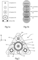
- each of these "tower” speakers typically has, along its respective longitudinal structure, a plurality of speakers equally spaced between them, and two openings in the lower portion of this structure.
- the number of acoustic interferences, in the prior art acoustic speakers, between the sound waves emitted by the respective speakers is less than the number of speakers themselves. This does not allow, for example, reproduction of the audio signal corresponding to a specific musical instrument, and thus to emulate its sound. Therefore, these prior art speakers do not allow a complete additive sound synthesis of the sound waves emitted by the respective speakers to be obtained.
- the relevant prior art comprises the patent application GB 1303602 A , the patent application US 2010/177921 A , the patent application US 2012/195447 A1 , the patent US 8967323 B1 and the patent application EP0521655 A1 .
- the aim of the invention is to overcome the drawbacks mentioned above by making an improved acoustic speaker to optimise the reproduction of audio signals.
- Another aim of the invention is to make an acoustic speaker with a geometry which makes it possible to combine sound signals in order to obtain a wide range of sound varieties.
- Another aim of the invention is to provide an acoustic speaker which can handle high levels of acoustic output.
- Another aim of the invention is to provide an acoustic speaker which is stable and easily installed in sound systems arranged inside and/or outside different types of environments such as, for example, household environments, professional environments, theatres and so on.
- Another aim of the invention is to provide an acoustic speaker which is highly reliable, relatively easy to make, and has competitive costs if compared with the prior art.
- the present invention is directed to an acoustic speaker according to claim 1. Further aspects of the invention are according to the dependent claims.
- the specific object of the invention is therefore an acoustic speaker for the reproduction of audio signals, comprising a first speaker and a respective first chamber, for reproducing at least one first audio signal y 1 ( t ) in a first frequency range, a second speaker and a respective second chamber, for reproducing at least one second audio signal y 2 ( t ) in a second frequency range equal to or different from said first frequency range, and a third speaker and a respective third chamber, for reproducing at least one third audio signal y 3 ( t ) in a third frequency range equal to or different from said first frequency range and from said second frequency range, a main resonance chamber provided with a main opening, and a supporting structure of said speakers and said main resonance chamber.
- said acoustic speaker can be provided with a fourth speaker for reproducing at least one fourth audio signal y 4 ( t ) in a fourth frequency range equal to or different from said first frequency range, said second frequency range and said third frequency range, said fourth speaker can be inserted in said main opening and oriented along the Z axis.
- said equilateral triangle which circumscribes said main opening may comprise a first side, a second side and a third side
- said acoustic speaker also has a fourth secondary opening arranged in proximity to the middle of said third side, a fifth secondary opening arranged in proximity to the middle of said second side, and a sixth secondary opening arranged in proximity to the middle of said first side, wherein each of said fourth, fifth and sixth secondary openings is positioned at a respective vertex of a further equilateral triangle circumscribing said main opening, and wherein each of said fourth, fifth and sixth secondary openings has a substantially circular shape and is in fluid communication with said main resonance chamber.
- said resonance structure can comprise a first face, a second face and a third face, wherein said first face has an opening for the insertion of a first supporting element fixable to a first wall, said second face has an opening for the insertion of a second supporting element fixable to a second wall, and said third face has an opening for the insertion of a third supporting element fixable to a third wall.
- said resonance plate can be made using spruce wood laths.
- said resonance structure can have an internal surface made of posidonia oceanica.
- said internal surface of said resonance structure can be designed to absorb sound waves and vibrations generated by each of said first, second, third and fourth speaker, when in use, acoustically insulating said acoustic speaker from the external environment.
- the acoustic speaker for the reproduction of audio signals substantially comprises a resonance plate P1, a first speaker 100A, a second speaker 101A, a third speaker 102A, and a fourth speaker 103A, said speakers 100A, 101A, 102A and 103A being installable in said resonance plate P1, and a resonance structure P2 which can be coupled, in use, to said resonance plate P1.
- the resonance plate P1 of the speaker 1 has the shape substantially of an equilateral triangular and has a first L1, a second L2 and a third L3 side.
- each of said first L1, second L2 and third L3 side has a length of 50cm.
- said resonance plate P1 can have different shapes, such as, for example, a circular or square shape.
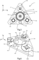
- Said resonance plate P1 has a main opening 103, positioned at the centre of said resonance plate P1, as well as a first secondary opening 100 for the insertion of said first speaker 100A, a second secondary opening 101 for the insertion of said second speaker 101A, and a third secondary opening 102 for the insertion of said third speaker 102A, each of said first secondary opening 100, second secondary opening 101 and third secondary opening 102 being positioned on a respective vertex of an equilateral triangle on an XY plane circumscribing said main opening 103.
- said fourth speaker 103A is inserted in said main opening 103.
- said resonance plate P1 has, therefore, both a structural function, being able to support said speakers 100A, 101A, 102A and 103A, and an acoustic resonance function, amplifying the sound waves coming from the same speakers 100A, 101A, 102A and 103A.
- each of said openings 100, 101, 102, 103 has a substantially circular shape.
- each of said secondary openings 100, 101, 102 has a diameter of 11cm (possibly extendable up to 13cm), whilst said main opening 103 has a diameter of 18cm.
- the shape of each of said openings 100, 101, 102, 103 may have a different shape from the above-mentioned circular shape.
- each of said openings 100, 101, 102 is arranged on a respective vertex of an equilateral triangle on the XY plane circumscribing said main opening 103.
- This arrangement of said openings 100, 101, 102, and 103, and therefore, of said speakers 100A, 101A, 102A, and 103A allows, as will be described in detail below, suitable combination of the audio signals emitted by the respective speakers 100A, 101A, 102A, and 103A.
- said resonance plate P1 further has a fourth secondary opening 104, a fifth secondary opening 105 and a sixth secondary opening 106.
- Each of said fourth 104, fifth 105 and sixth 106 secondary openings also has a substantially circular shape and is arranged at a respective vertex of a further equilateral triangle on the same plane XY circumscribing said main opening 103.
- each of said openings 104, 105 and 106 has a diameter of 5cm, however this size typically depends on the size of the speaker 1.
- said fourth secondary opening 104 is arranged in proximity to the middle of said third side L3
- said fifth secondary opening 105 is arranged in proximity to the middle of said second side L2
- said sixth secondary opening 106 is arranged in proximity to the middle of said first side L1.
- the sound waves emitted along the direction of a Z axis, perpendicular to the XY plane, in the negative Z direction (that is, behind said resonance plate P1) from said fourth speaker 103A are emitted again along the direction of the Z axis, in the positive Z direction, (that is, in front of said resonance plate P1), thus amplifying the sound reproduced by said fourth speaker 103A.
- the rear sound waves emitted by said fourth 103A speaker are re-timed with the front sound waves emitted by the same fourth 103A speaker (this technique is called "bass reflex" in technical jargon).
- said resonance plate P1 is made of spruce wood strips.
- this material has excellent properties for amplification of the sound waves generated by an instrument or device.
- said resonance plate P1 can be made from other materials such as maple or plane tree wood.
- said resonance plate P1 has a height of 40 cm and a thickness of 30mm.
- the acoustic speaker 1 has a plurality of speakers 100A, 101A, 102A, and 103A coupled to respective resonance chambers and able to emit respective audio signals in predetermined frequency ranges within the range of frequencies audible by the human ear between 20Hz-20kHz.
- said first speaker 100A is configured to reproduce at least one first audio signal y 1 ( t ) in a first frequency range
- said second speaker 101A is configured to reproduce at least one second audio signal y 2 ( t ) in a second frequency range equal to or different from said first frequency range
- said third speaker 102A is configured to reproduce at least one third audio signal y 3 ( t ) in a third frequency range equal to or different from said first frequency range and from said second frequency range
- said fourth speaker 103A is configured to reproduce at least one fourth audio signal y 4 ( t ) in a fourth frequency range equal or different from said first frequency range, from said second frequency range and from said third frequency rage.
- said first range of frequencies is equal to 2kHz-20kHz
- said second range of frequencies is equal to 500Hz-5kHz
- said third range of frequencies is equal to 50Hz-2kHz
- said fourth range of frequencies is equal to 150Hz-9kHz.
- said first speaker 100A allows the reproduction of audio signals at high frequencies (this speaker is called “Tweeter” in jargon)
- said second speaker 101A allows the reproduction of audio signals at low frequencies (this speaker is called “Woofer” in jargon)
- said third speaker 102A is able to reproduce audio signals at medium frequencies (this speaker is called “Midrange” in jargon)
- said fourth speaker 103A allows the reproduction of audio signals at very low frequencies (this speaker is called “Subwoofer” in jargon).
- said acoustic speaker 1 may comprise, for example, a high-frequency amplifier and two medium-frequency stereo amplifiers without any low-frequency amplifier, or a high-frequency amplifier, two medium-frequency stereo amplifiers, and a low-frequency amplifier.
- Figures 3B and 3C show the acoustic interference between the sound waves emitted by three and four speakers respectively, according to the layout of the acoustic speaker 1 shown in Figure 3A .
- Figure 3B illustrates an embodiment of the invention wherein said acoustic speaker 1 comprises a high frequency speaker 100A inserted in said opening 100, a low frequency speaker 101A inserted in said opening 101, and a medium frequency speaker 102A inserted in said opening 102.
- FIG. 3C illustrates an embodiment of the invention wherein said acoustic speaker 1 comprises a high frequency speaker 100A inserted in said opening 100, a low frequency speaker 101A inserted in said opening 101, a medium frequency speaker 102A inserted in said opening 102, and a very low frequency speaker 103A inserted in said main opening 103.
- the number of acoustic interferences between the sound waves emitted by the respective speakers is greater than the number of acoustic interferences of the case described above and illustrated in Figure 3B .
- Figures 4C to 4F show in schematic view a graphic representation of acoustic interference between sound waves generated respectively by four speakers in three frequency ranges different from each other, by six speakers in three frequency ranges different from each other, by seven speakers in three frequency ranges different from each other and by six speakers in four frequency ranges different from each other.
- said first 100A, second 101A and third 102A speakers are arranged on the same XY plane and are oriented in the same direction along the Z axis perpendicular to said XY plane, so as to reproduce, in the positive Z direction, a further audio signal y(t) resulting from the combination of said first audio signal y 1 ( t ), said second audio signal y 2 ( t ) and said third audio signal y 3 ( t ).
- the Fast Fourier Transform is an optimised algorithm for calculating the Discrete Fourier Transform (DFT) or its inverse, and is typically used within dedicated software applications for personal computers, for example, in digital signal processing.
- acoustic speaker 1 is able to reproduce the waveform corresponding to the timbre of a specific instrument, such as a violin or guitar, emulating its sound.
- the waveform of a signal and its envelope over time can be obtained by combining multiple frequency sinusoidal waves of a fundamental frequency (the so-called " harmonics").
- This can also be applied to the waveforms generated by a musical instrument, allowing, for example, the timbre and sound to be broken down into individual sine waves and vice versa.
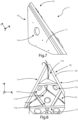
- the acoustic speaker 1 comprises a P2 resonance structure which can be coupled, in use, to said resonance plate P1.
- said resonance structure P2 has a substantially regular pyramid shape with an equilateral triangular base (or equilateral tetrahedral base), wherein the angle at the vertex of each side face is right-angled.
- said resonance structure P2 defines, together with said resonance plate (P1), a main resonance chamber 113, associated with said main opening 103 and, when present, with said fourth speaker 103A; as well as a first secondary resonance chamber 110, a second secondary resonance chamber 111, and a third secondary resonance chamber 112, associated respectively to said first secondary opening 100 and to said first speaker 100A, to said second secondary opening 101 and to said second speaker 101A and to said third secondary opening 102 and to said third speaker 102A.
- Said main resonance chamber 113 has a substantially prism shape with a hexagonal base, wherein said hexagonal base circumscribes said main opening 103.
- each of said first 110, second 111 and third 112 secondary resonance chambers has a substantially pyramid shape with a triangular base, wherein said triangular base coincides with each triangle circumscribing said respective first 100, second 101 and third 102 secondary opening and the height is positioned on an axis perpendicular to said triangular base and parallel to the Z axis.
- said main resonance chamber 113 in the presence of said fourth speaker, becomes active, amplifying the further audio signal y(t) (or Additive Synthesis signal) through continuous pressure flows out of phase between the main opening 103, in the positive Z direction, and said fourth secondary opening 104, said fifth secondary opening 105 and said sixth secondary opening 106.
- the resonance structure P2 comprises a first face 11, a second face 12 and a third face 13.
- said first face 11 has a further fourth opening 114 for the insertion of a first supporting element fixable to a first wall
- said second face 12 has a further fifth opening 115 for the insertion of a second supporting element fixable to a second wall
- said third face 13 has a further sixth opening 116 for the insertion of a third supporting element fixable to a third wall.
- each supporting element is able to constrain the respective face by which it is fixed to a wall by means of connecting means such as screws and the like.
- said acoustic speaker 1 can be positioned between two adjacent walls and the ceiling in such a way that, for example, said first face 11 is fixed to a first wall, said second face 12 is fixed to a second wall and said third face 13 is fixed to said ceiling.
- said resonance structure P2' has an internal surface P2' made by means of posidonia oceanica to acoustically isolate said speaker 1.
- said internal surface P2' of said resonance structure P2 is able to absorb sound waves and vibrations generated along the direction of the Z axis, in the negative Z direction, by each of said first 100A, second 101A, third 102A and fourth 103A speakers, when in use, acoustically isolating said acoustic speaker 1 from the external environment.
- this main resonance chamber 113 in the absence of the fourth speaker 103A, is not coated with resin and posidonia oceanica like, for example, the inner surface of a guitar.
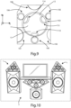
- Figure 9 shows, according to the embodiment described, the coupling between the resonance plate P1 and the resonance structure P2 of the acoustic speaker 1.
- the acoustic speaker 1 can be connected to an audio system S comprising electrical signal generation devices and/or display devices and/or desktop PC.
- said acoustic speaker 1 is positioned on any of said first face 11, second face 12 and said third face 13, being inclined by 45° degrees in the direction of the positive Z axes, in such a way as to emulate the reflection phenomenon typical of classical theatres.
- Said S system can be, for example, a Hi-Fi system ("High Fidelity") equipped, among other things, with integrated amplifiers, computers, and/or A/D converters, and possibly connected to a TV or projector.
- Hi-Fi system High Fidelity
- said audio system S can comprise additional resonance chambers, equipped with a low frequency amplifier, on which said acoustic speaker 1 can be positioned.
- this configuration allows a total output of between 1400W and 2000W to be reached.
- a first advantage of the acoustic speaker according to the invention is to optimise the reproduction of audio signals.
- a further advantage of the acoustic speaker according to the invention is that it handles high sound output levels whilst occupying little space.
- a further advantage of the acoustic speaker according to the invention is that it can be easily installed and configured in audio systems located inside and/or outside of different rooms or easily placed on any side and/or top of walls.
- a further advantage of the acoustic speaker according to the invention is that it comprises a plurality of speakers isolated acoustically from each other.
- a further advantage of the acoustic speaker according to the invention is that it has a symmetrical and configurable structure. Moreover, the arrangement of the speakers, as described above, allows the audio signals associated with each speaker to be combined with a respective frequency.
- a further advantage of the speaker according to the invention is that it has an equilateral rectangular pyramidal shape which guarantees greater stability and fewer vibrations compared to the prior art systems.
- a further advantage of the speaker according to the invention is that it is a four-sided element and therefore, for the same volume, it has a smaller total surface area than the prior art 6-sided systems. This allows a considerable saving of time and materials during construction.
Landscapes
- Health & Medical Sciences (AREA)
- Otolaryngology (AREA)
- Physics & Mathematics (AREA)
- Engineering & Computer Science (AREA)
- Acoustics & Sound (AREA)
- Signal Processing (AREA)
- Obtaining Desirable Characteristics In Audible-Bandwidth Transducers (AREA)
Claims (7)
- Haut-parleur acoustique (1) pour la reproduction de signaux audio, comprenant un premier haut-parleur (100A) et une première chambre respective, pour reproduire au moins un premier signal audio y1(t) dans une première plage de fréquences, un deuxième haut-parleur (101A) et une deuxième chambre respective, pour reproduire au moins un deuxième signal audio signal y2(t) dans une deuxième plage de fréquences égale ou différente de ladite première plage de fréquences, et un troisième haut-parleur (102A) et une troisième chambre respective, pour reproduire au moins un troisième signal audio y3(t) dans une troisième plage de fréquences égale ou différente de ladite première plage de fréquences et de ladite deuxième plage de fréquences,une chambre de résonance principale (113) pourvue d'une ouverture principale (103), etune structure de support desdits haut-parleurs et de ladite chambre de résonance principale (113),dans lequel chacun desdits premier (100A), deuxième (101A) et troisième (102A) haut-parleurs est agencé sur un sommet respectif d'un triangle équilatéral qui circonscrit ladite ouverture principale (103), lesdits premier (100A), deuxième (101A) et troisième (102A) haut-parleur et ladite ouverture principale (103) étant agencés sur un même plan XY et orientés selon une même direction selon un axe Z, perpendiculaire audit plan XY, de manière à reproduire un signal audio supplémentaire y(t) résultant de la combinaison dudit au moins un premier signal audio y1(t), dudit au moins un deuxième signal audio y2(t) et dudit au moins un troisième signal audio y3(t),dans lequel ladite structure de support est une plaque de résonance (P1) coplanaire audit triangle équilatéral, ladite plaque de résonance (P1) présentant une ouverture principale coïncidant avec ladite ouverture principale (103) de ladite chambre de résonance principale (113), une première ouverture secondaire (100) pour l'insertion dudit premier haut-parleur (100A), une deuxième ouverture secondaire (101) pour l'insertion dudit deuxième haut-parleur (101A) et une troisième ouverture secondaire (102) pour l'insertion dudit troisième haut-parleur (102A), dans lequel ledit haut-parleur acoustique (1) comprend une structure de résonance (P2) couplée à ladite plaque de résonance (P1), du côté opposé à la direction le long de laquelle sont orientés lesdits premier (100A), deuxième (101A) et troisième (102A) haut-parleurs et ladite ouverture principale (103), ladite structure de résonance (P2) présentant une forme de pyramide régulière avec une base triangulaire équilatérale et dans lequel l'angle au sommet de chaque face latérale est à angle droit; ladite structure de résonance (P2) définissant, avec ladite plaque de résonance (P1), lesdites première (110), deuxième (111) et troisième (112) chambres de résonance,ledit haut-parleur acoustique (1) étant caractérisé en ce que ladite structure de résonance (P2) définit, avec ladite plaque de résonance (P1), ladite première chambre de résonance (110), ladite deuxième chambre de résonance (111) et ladite troisième chambre de résonance (112), dans lequel chacune desdites première (110), deuxième (111) et troisième (112) chambres de résonance a une forme de pyramide régulière avec une base triangulaire, dans lequel ladite base triangulaire coïncide avec un triangle équilatéral circonscrivant lesdites première (100), deuxième (101) et troisième (102) ouvertures secondaires et dans lequel la hauteur sur un axe perpendiculaire à ladite base triangulaire est parallèle audit axe Zladite structure de résonance (P2) définissant en outre, avec ladite plaque de résonance (P1), ladite chambre de résonance principale (113) ayant sensiblement une forme de prisme avec une base hexagonale.
- Haut-parleur acoustique (1) selon la revendication précédente, caractériséen ce que ledit haut-parleur acoustique (1) est pourvu d'un quatrième haut-parleur (103A) pour reproduire au moins un quatrième signal audio y4(t) dans une quatrième plage de fréquences égale ou différente de ladite première plage de fréquences, ladite deuxième plage de fréquences et ladite troisième plage de fréquences,en ce que ledit quatrième haut-parleur (103A) est inséré dans ladite ouverture principale (103) et orienté le long de l'axe Z.
- Haut-parleur acoustique (1) selon l'une quelconque des revendications précédentes, caractérisé en ce que ledit triangle équilatéral qui circonscrit ladite ouverture principale (103) comprend un premier côté (L1), un deuxième côté (L2) et un troisième côté (L3),et dans lequel ledit haut-parleur acoustique (1) a en outre une quatrième ouverture secondaire (104) agencée à proximité du milieu dudit troisième côté (L3), une cinquième ouverture secondaire (105) agencée à proximité du milieu dudit deuxième côté (L2), et une sixième ouverture secondaire (106) agencée à proximité du milieu dudit premier côté (L1),dans lequel chacune desdites quatrième (104), cinquième (105) et sixième (106) ouvertures secondaires est agencée à un sommet respectif d'un triangle équilatéral supplémentaire qui circonscrit ladite ouverture principale (103), etdans lequel chacune desdites quatrième (104), cinquième (105) et sixième (106) ouvertures secondaires a une forme sensiblement circulaire et est en communication fluidique avec ladite chambre de résonance principale (113).
- Haut-parleur acoustique (1) selon l'une quelconque des revendications 1 ou 3, caractérisé en ce que ladite structure de résonance (P2) comprend une première face (11), une deuxième face (12) et une troisième face (13), dans lequelladite première face (11) a une ouverture (114) pour insérer un premier élément de support pouvant être fixé à une première paroi,ladite deuxième face (12) a une ouverture (115) pour insérer un deuxième élément de support pouvant être fixé à une deuxième paroi,ladite troisième face (13) a une ouverture (116) pour insérer un troisième élément de support pouvant être fixé à une troisième paroi.
- Haut-parleur acoustique (1) selon l'une quelconque des revendications précédentes, caractérisé en ce que ladite plaque de résonance (P1) est constituée de lattes de bois d'épicéa.
- Haut-parleur acoustique (1) selon l'une quelconque des revendications 1 ou 3 à 5, caractérisé en ce que ladite structure de résonance (P2) a une surface interne (P2') en posidonie océanique.
- Haut-parleur acoustique (1) selon la revendication 2, caractérisé en ce que ladite surface interne (P2') de ladite structure de résonance (P2) est conçue pour absorber les ondes sonores et les vibrations générées par chacun desdits premier (100A), deuxième (101A), troisième (102A) et quatrième (103A) haut-parleur, lorsqu'ils sont utilisés, isolant acoustiquement ledit haut-parleur acoustique (1) de l'environnement externe.
Applications Claiming Priority (1)
| Application Number | Priority Date | Filing Date | Title |
|---|---|---|---|
| IT102019000020664A IT201900020664A1 (it) | 2019-11-08 | 2019-11-08 | Diffusore acustico. |
Publications (3)
| Publication Number | Publication Date |
|---|---|
| EP3820159A1 EP3820159A1 (fr) | 2021-05-12 |
| EP3820159B1 true EP3820159B1 (fr) | 2023-06-21 |
| EP3820159C0 EP3820159C0 (fr) | 2023-06-21 |
Family
ID=69811729
Family Applications (1)
| Application Number | Title | Priority Date | Filing Date |
|---|---|---|---|
| EP20204192.7A Active EP3820159B1 (fr) | 2019-11-08 | 2020-10-27 | Hautparleur |
Country Status (2)
| Country | Link |
|---|---|
| EP (1) | EP3820159B1 (fr) |
| IT (1) | IT201900020664A1 (fr) |
Families Citing this family (2)
| Publication number | Priority date | Publication date | Assignee | Title |
|---|---|---|---|---|
| CN113852901B (zh) * | 2021-08-27 | 2023-11-07 | 潍坊歌尔丹拿电子科技有限公司 | 测试治具和测试装置 |
| CN115993752A (zh) * | 2022-12-30 | 2023-04-21 | 峰米(重庆)创新科技有限公司 | 投影设备 |
Citations (1)
| Publication number | Priority date | Publication date | Assignee | Title |
|---|---|---|---|---|
| EP0521655A1 (fr) * | 1991-06-25 | 1993-01-07 | Yugen Kaisha Taguchi Seisakusho | Cluster des hàut-parleurs |
Family Cites Families (4)
| Publication number | Priority date | Publication date | Assignee | Title |
|---|---|---|---|---|
| GB1303602A (fr) * | 1971-03-12 | 1973-01-17 | ||
| US20100177921A1 (en) * | 2009-01-14 | 2010-07-15 | Richard Bos | Response speaker system |
| JP5417352B2 (ja) * | 2011-01-27 | 2014-02-12 | 株式会社東芝 | 音場制御装置及び方法 |
| US8967323B1 (en) * | 2012-12-27 | 2015-03-03 | James Robert Grenier | Multi-directional foldback and front of house speaker enclosure |
-
2019
- 2019-11-08 IT IT102019000020664A patent/IT201900020664A1/it unknown
-
2020
- 2020-10-27 EP EP20204192.7A patent/EP3820159B1/fr active Active
Patent Citations (1)
| Publication number | Priority date | Publication date | Assignee | Title |
|---|---|---|---|---|
| EP0521655A1 (fr) * | 1991-06-25 | 1993-01-07 | Yugen Kaisha Taguchi Seisakusho | Cluster des hàut-parleurs |
Also Published As
| Publication number | Publication date |
|---|---|
| IT201900020664A1 (it) | 2021-05-08 |
| EP3820159A1 (fr) | 2021-05-12 |
| EP3820159C0 (fr) | 2023-06-21 |
Similar Documents
| Publication | Publication Date | Title |
|---|---|---|
| US3983333A (en) | Loud speaker system | |
| CN101627640B (zh) | 在半球内辐射声波的扬声器装置 | |
| US20170055067A1 (en) | Thin high performance constant directivity waveguide and speaker | |
| US8774424B2 (en) | Apparatus for reproduction of sound | |
| US20090214049A1 (en) | Electrostatic Loudspeaker Array | |
| US9351059B1 (en) | Orthogonal open back speaker system | |
| US9161119B2 (en) | Phi-based enclosure for speaker systems | |
| EP3820159B1 (fr) | Hautparleur | |
| US20150382103A1 (en) | Phi-Based Enclosure for Speaker Systems | |
| CN1663321A (zh) | 应用单一相加强孔径扬声器的声音再现 | |
| US20090290724A1 (en) | Loudspeaker system and loudspeaker having a tweeter array | |
| US4870691A (en) | Load and dispersion cell for sound | |
| US4276446A (en) | Acoustic transducer system | |
| Boyce | Introduction to Live Sound Reinforcement: The Science, the Art, and the Practice | |
| RU2612535C2 (ru) | Громкоговоритель | |
| CN105706461B (zh) | 扬声器换能装置 | |
| CN207744135U (zh) | 一种阵列高音频音箱 | |
| RU2661543C1 (ru) | Составной соосный диффузор динамика | |
| CN214627344U (zh) | 一种多通道对称结构平面波导管号角 | |
| US8379892B1 (en) | Array of high frequency loudspeakers | |
| IT201900004000U1 (it) | Diffusore acustico. | |
| CN114422911A (zh) | 一种同轴喇叭与高音号角组合的线性阵列音箱 | |
| US7773765B1 (en) | Rectangular horn for varied acoustic drivers | |
| US5027411A (en) | High frequency loudspeaker | |
| CN223402561U (zh) | 一种双面低频鼓音箱 |
Legal Events
| Date | Code | Title | Description |
|---|---|---|---|
| PUAI | Public reference made under article 153(3) epc to a published international application that has entered the european phase |
Free format text: ORIGINAL CODE: 0009012 |
|
| STAA | Information on the status of an ep patent application or granted ep patent |
Free format text: STATUS: THE APPLICATION HAS BEEN PUBLISHED |
|
| AK | Designated contracting states |
Kind code of ref document: A1 Designated state(s): AL AT BE BG CH CY CZ DE DK EE ES FI FR GB GR HR HU IE IS IT LI LT LU LV MC MK MT NL NO PL PT RO RS SE SI SK SM TR |
|
| STAA | Information on the status of an ep patent application or granted ep patent |
Free format text: STATUS: REQUEST FOR EXAMINATION WAS MADE |
|
| 17P | Request for examination filed |
Effective date: 20210713 |
|
| RBV | Designated contracting states (corrected) |
Designated state(s): AL AT BE BG CH CY CZ DE DK EE ES FI FR GB GR HR HU IE IS IT LI LT LU LV MC MK MT NL NO PL PT RO RS SE SI SK SM TR |
|
| GRAP | Despatch of communication of intention to grant a patent |
Free format text: ORIGINAL CODE: EPIDOSNIGR1 |
|
| STAA | Information on the status of an ep patent application or granted ep patent |
Free format text: STATUS: GRANT OF PATENT IS INTENDED |
|
| INTG | Intention to grant announced |
Effective date: 20230109 |
|
| GRAS | Grant fee paid |
Free format text: ORIGINAL CODE: EPIDOSNIGR3 |
|
| GRAA | (expected) grant |
Free format text: ORIGINAL CODE: 0009210 |
|
| STAA | Information on the status of an ep patent application or granted ep patent |
Free format text: STATUS: THE PATENT HAS BEEN GRANTED |
|
| AK | Designated contracting states |
Kind code of ref document: B1 Designated state(s): AL AT BE BG CH CY CZ DE DK EE ES FI FR GB GR HR HU IE IS IT LI LT LU LV MC MK MT NL NO PL PT RO RS SE SI SK SM TR |
|
| REG | Reference to a national code |
Ref country code: CH Ref legal event code: EP |
|
| REG | Reference to a national code |
Ref country code: DE Ref legal event code: R096 Ref document number: 602020012721 Country of ref document: DE |
|
| REG | Reference to a national code |
Ref country code: AT Ref legal event code: REF Ref document number: 1581763 Country of ref document: AT Kind code of ref document: T Effective date: 20230715 |
|
| REG | Reference to a national code |
Ref country code: IE Ref legal event code: FG4D |
|
| U01 | Request for unitary effect filed |
Effective date: 20230707 |
|
| U07 | Unitary effect registered |
Designated state(s): AT BE BG DE DK EE FI FR IT LT LU LV MT NL PT SE SI Effective date: 20230718 |
|
| REG | Reference to a national code |
Ref country code: LT Ref legal event code: MG9D |
|
| PG25 | Lapsed in a contracting state [announced via postgrant information from national office to epo] |
Ref country code: NO Free format text: LAPSE BECAUSE OF FAILURE TO SUBMIT A TRANSLATION OF THE DESCRIPTION OR TO PAY THE FEE WITHIN THE PRESCRIBED TIME-LIMIT Effective date: 20230921 |
|
| PG25 | Lapsed in a contracting state [announced via postgrant information from national office to epo] |
Ref country code: RS Free format text: LAPSE BECAUSE OF FAILURE TO SUBMIT A TRANSLATION OF THE DESCRIPTION OR TO PAY THE FEE WITHIN THE PRESCRIBED TIME-LIMIT Effective date: 20230621 Ref country code: HR Free format text: LAPSE BECAUSE OF FAILURE TO SUBMIT A TRANSLATION OF THE DESCRIPTION OR TO PAY THE FEE WITHIN THE PRESCRIBED TIME-LIMIT Effective date: 20230621 Ref country code: GR Free format text: LAPSE BECAUSE OF FAILURE TO SUBMIT A TRANSLATION OF THE DESCRIPTION OR TO PAY THE FEE WITHIN THE PRESCRIBED TIME-LIMIT Effective date: 20230922 |
|
| PG25 | Lapsed in a contracting state [announced via postgrant information from national office to epo] |
Ref country code: SK Free format text: LAPSE BECAUSE OF FAILURE TO SUBMIT A TRANSLATION OF THE DESCRIPTION OR TO PAY THE FEE WITHIN THE PRESCRIBED TIME-LIMIT Effective date: 20230621 |
|
| PG25 | Lapsed in a contracting state [announced via postgrant information from national office to epo] |
Ref country code: ES Free format text: LAPSE BECAUSE OF FAILURE TO SUBMIT A TRANSLATION OF THE DESCRIPTION OR TO PAY THE FEE WITHIN THE PRESCRIBED TIME-LIMIT Effective date: 20230621 |
|
| PG25 | Lapsed in a contracting state [announced via postgrant information from national office to epo] |
Ref country code: IS Free format text: LAPSE BECAUSE OF FAILURE TO SUBMIT A TRANSLATION OF THE DESCRIPTION OR TO PAY THE FEE WITHIN THE PRESCRIBED TIME-LIMIT Effective date: 20231021 |
|
| PG25 | Lapsed in a contracting state [announced via postgrant information from national office to epo] |
Ref country code: SM Free format text: LAPSE BECAUSE OF FAILURE TO SUBMIT A TRANSLATION OF THE DESCRIPTION OR TO PAY THE FEE WITHIN THE PRESCRIBED TIME-LIMIT Effective date: 20230621 Ref country code: SK Free format text: LAPSE BECAUSE OF FAILURE TO SUBMIT A TRANSLATION OF THE DESCRIPTION OR TO PAY THE FEE WITHIN THE PRESCRIBED TIME-LIMIT Effective date: 20230621 Ref country code: RO Free format text: LAPSE BECAUSE OF FAILURE TO SUBMIT A TRANSLATION OF THE DESCRIPTION OR TO PAY THE FEE WITHIN THE PRESCRIBED TIME-LIMIT Effective date: 20230621 Ref country code: IS Free format text: LAPSE BECAUSE OF FAILURE TO SUBMIT A TRANSLATION OF THE DESCRIPTION OR TO PAY THE FEE WITHIN THE PRESCRIBED TIME-LIMIT Effective date: 20231021 Ref country code: ES Free format text: LAPSE BECAUSE OF FAILURE TO SUBMIT A TRANSLATION OF THE DESCRIPTION OR TO PAY THE FEE WITHIN THE PRESCRIBED TIME-LIMIT Effective date: 20230621 Ref country code: CZ Free format text: LAPSE BECAUSE OF FAILURE TO SUBMIT A TRANSLATION OF THE DESCRIPTION OR TO PAY THE FEE WITHIN THE PRESCRIBED TIME-LIMIT Effective date: 20230621 |
|
| PG25 | Lapsed in a contracting state [announced via postgrant information from national office to epo] |
Ref country code: PL Free format text: LAPSE BECAUSE OF FAILURE TO SUBMIT A TRANSLATION OF THE DESCRIPTION OR TO PAY THE FEE WITHIN THE PRESCRIBED TIME-LIMIT Effective date: 20230621 |
|
| REG | Reference to a national code |
Ref country code: DE Ref legal event code: R097 Ref document number: 602020012721 Country of ref document: DE |
|
| PLBE | No opposition filed within time limit |
Free format text: ORIGINAL CODE: 0009261 |
|
| STAA | Information on the status of an ep patent application or granted ep patent |
Free format text: STATUS: NO OPPOSITION FILED WITHIN TIME LIMIT |
|
| 26N | No opposition filed |
Effective date: 20240322 |
|
| U21 | Renewal fee for the european patent with unitary effect paid with additional fee |
Year of fee payment: 4 Effective date: 20240419 |
|
| PG25 | Lapsed in a contracting state [announced via postgrant information from national office to epo] |
Ref country code: MC Free format text: LAPSE BECAUSE OF FAILURE TO SUBMIT A TRANSLATION OF THE DESCRIPTION OR TO PAY THE FEE WITHIN THE PRESCRIBED TIME-LIMIT Effective date: 20230621 |
|
| REG | Reference to a national code |
Ref country code: CH Ref legal event code: PL |
|
| PG25 | Lapsed in a contracting state [announced via postgrant information from national office to epo] |
Ref country code: CH Free format text: LAPSE BECAUSE OF NON-PAYMENT OF DUE FEES Effective date: 20231031 |
|
| PG25 | Lapsed in a contracting state [announced via postgrant information from national office to epo] |
Ref country code: CH Free format text: LAPSE BECAUSE OF NON-PAYMENT OF DUE FEES Effective date: 20231031 |
|
| PG25 | Lapsed in a contracting state [announced via postgrant information from national office to epo] |
Ref country code: IE Free format text: LAPSE BECAUSE OF NON-PAYMENT OF DUE FEES Effective date: 20231027 |
|
| PG25 | Lapsed in a contracting state [announced via postgrant information from national office to epo] |
Ref country code: IE Free format text: LAPSE BECAUSE OF NON-PAYMENT OF DUE FEES Effective date: 20231027 |
|
| U20 | Renewal fee for the european patent with unitary effect paid |
Year of fee payment: 5 Effective date: 20241024 |
|
| PGFP | Annual fee paid to national office [announced via postgrant information from national office to epo] |
Ref country code: GB Payment date: 20250320 Year of fee payment: 5 |
|
| PG25 | Lapsed in a contracting state [announced via postgrant information from national office to epo] |
Ref country code: CY Free format text: LAPSE BECAUSE OF FAILURE TO SUBMIT A TRANSLATION OF THE DESCRIPTION OR TO PAY THE FEE WITHIN THE PRESCRIBED TIME-LIMIT; INVALID AB INITIO Effective date: 20201027 |
|
| PG25 | Lapsed in a contracting state [announced via postgrant information from national office to epo] |
Ref country code: HU Free format text: LAPSE BECAUSE OF FAILURE TO SUBMIT A TRANSLATION OF THE DESCRIPTION OR TO PAY THE FEE WITHIN THE PRESCRIBED TIME-LIMIT; INVALID AB INITIO Effective date: 20201027 |
|
| PG25 | Lapsed in a contracting state [announced via postgrant information from national office to epo] |
Ref country code: TR Free format text: LAPSE BECAUSE OF FAILURE TO SUBMIT A TRANSLATION OF THE DESCRIPTION OR TO PAY THE FEE WITHIN THE PRESCRIBED TIME-LIMIT Effective date: 20230621 |