EP3820547B1 - Einspritzvorrichtung für flüssigkeiten - Google Patents
Einspritzvorrichtung für flüssigkeiten Download PDFInfo
- Publication number
- EP3820547B1 EP3820547B1 EP19756220.0A EP19756220A EP3820547B1 EP 3820547 B1 EP3820547 B1 EP 3820547B1 EP 19756220 A EP19756220 A EP 19756220A EP 3820547 B1 EP3820547 B1 EP 3820547B1
- Authority
- EP
- European Patent Office
- Prior art keywords
- tube
- reservoir
- cam
- fluid
- selector
- Prior art date
- Legal status (The legal status is an assumption and is not a legal conclusion. Google has not performed a legal analysis and makes no representation as to the accuracy of the status listed.)
- Active
Links
Images






Classifications
-
- A—HUMAN NECESSITIES
- A61—MEDICAL OR VETERINARY SCIENCE; HYGIENE
- A61M—DEVICES FOR INTRODUCING MEDIA INTO, OR ONTO, THE BODY; DEVICES FOR TRANSDUCING BODY MEDIA OR FOR TAKING MEDIA FROM THE BODY; DEVICES FOR PRODUCING OR ENDING SLEEP OR STUPOR
- A61M5/00—Devices for bringing media into the body in a subcutaneous, intra-vascular or intramuscular way; Accessories therefor, e.g. filling or cleaning devices, arm-rests
- A61M5/178—Syringes
- A61M5/19—Syringes having more than one chamber, e.g. including a manifold coupling two parallelly aligned syringes through separate channels to a common discharge assembly
-
- A—HUMAN NECESSITIES
- A61—MEDICAL OR VETERINARY SCIENCE; HYGIENE
- A61M—DEVICES FOR INTRODUCING MEDIA INTO, OR ONTO, THE BODY; DEVICES FOR TRANSDUCING BODY MEDIA OR FOR TAKING MEDIA FROM THE BODY; DEVICES FOR PRODUCING OR ENDING SLEEP OR STUPOR
- A61M5/00—Devices for bringing media into the body in a subcutaneous, intra-vascular or intramuscular way; Accessories therefor, e.g. filling or cleaning devices, arm-rests
- A61M5/14—Infusion devices, e.g. infusing by gravity; Blood infusion; Accessories therefor
- A61M5/142—Pressure infusion, e.g. using pumps
- A61M5/14212—Pumping with an aspiration and an expulsion action
- A61M5/14232—Roller pumps
-
- A—HUMAN NECESSITIES
- A61—MEDICAL OR VETERINARY SCIENCE; HYGIENE
- A61M—DEVICES FOR INTRODUCING MEDIA INTO, OR ONTO, THE BODY; DEVICES FOR TRANSDUCING BODY MEDIA OR FOR TAKING MEDIA FROM THE BODY; DEVICES FOR PRODUCING OR ENDING SLEEP OR STUPOR
- A61M39/00—Tubes, tube connectors, tube couplings, valves, access sites or the like, specially adapted for medical use
- A61M39/22—Valves or arrangement of valves
- A61M39/223—Multiway valves
-
- A—HUMAN NECESSITIES
- A61—MEDICAL OR VETERINARY SCIENCE; HYGIENE
- A61M—DEVICES FOR INTRODUCING MEDIA INTO, OR ONTO, THE BODY; DEVICES FOR TRANSDUCING BODY MEDIA OR FOR TAKING MEDIA FROM THE BODY; DEVICES FOR PRODUCING OR ENDING SLEEP OR STUPOR
- A61M39/00—Tubes, tube connectors, tube couplings, valves, access sites or the like, specially adapted for medical use
- A61M39/22—Valves or arrangement of valves
- A61M39/28—Clamping means for squeezing flexible tubes, e.g. roller clamps
- A61M39/285—Cam clamps, e.g. roller clamps with eccentric axis
-
- A—HUMAN NECESSITIES
- A61—MEDICAL OR VETERINARY SCIENCE; HYGIENE
- A61M—DEVICES FOR INTRODUCING MEDIA INTO, OR ONTO, THE BODY; DEVICES FOR TRANSDUCING BODY MEDIA OR FOR TAKING MEDIA FROM THE BODY; DEVICES FOR PRODUCING OR ENDING SLEEP OR STUPOR
- A61M5/00—Devices for bringing media into the body in a subcutaneous, intra-vascular or intramuscular way; Accessories therefor, e.g. filling or cleaning devices, arm-rests
- A61M5/14—Infusion devices, e.g. infusing by gravity; Blood infusion; Accessories therefor
- A61M5/142—Pressure infusion, e.g. using pumps
- A61M5/14244—Pressure infusion, e.g. using pumps adapted to be carried by the patient, e.g. portable on the body
- A61M5/14248—Pressure infusion, e.g. using pumps adapted to be carried by the patient, e.g. portable on the body of the skin patch type
-
- A—HUMAN NECESSITIES
- A61—MEDICAL OR VETERINARY SCIENCE; HYGIENE
- A61M—DEVICES FOR INTRODUCING MEDIA INTO, OR ONTO, THE BODY; DEVICES FOR TRANSDUCING BODY MEDIA OR FOR TAKING MEDIA FROM THE BODY; DEVICES FOR PRODUCING OR ENDING SLEEP OR STUPOR
- A61M5/00—Devices for bringing media into the body in a subcutaneous, intra-vascular or intramuscular way; Accessories therefor, e.g. filling or cleaning devices, arm-rests
- A61M5/14—Infusion devices, e.g. infusing by gravity; Blood infusion; Accessories therefor
- A61M5/162—Needle sets, i.e. connections by puncture between reservoir and tube ; Connections between reservoir and tube
-
- A—HUMAN NECESSITIES
- A61—MEDICAL OR VETERINARY SCIENCE; HYGIENE
- A61M—DEVICES FOR INTRODUCING MEDIA INTO, OR ONTO, THE BODY; DEVICES FOR TRANSDUCING BODY MEDIA OR FOR TAKING MEDIA FROM THE BODY; DEVICES FOR PRODUCING OR ENDING SLEEP OR STUPOR
- A61M5/00—Devices for bringing media into the body in a subcutaneous, intra-vascular or intramuscular way; Accessories therefor, e.g. filling or cleaning devices, arm-rests
- A61M5/14—Infusion devices, e.g. infusing by gravity; Blood infusion; Accessories therefor
- A61M5/168—Means for controlling media flow to the body or for metering media to the body, e.g. drip meters, counters ; Monitoring media flow to the body
- A61M5/16804—Flow controllers
- A61M5/16813—Flow controllers by controlling the degree of opening of the flow line
-
- A—HUMAN NECESSITIES
- A61—MEDICAL OR VETERINARY SCIENCE; HYGIENE
- A61M—DEVICES FOR INTRODUCING MEDIA INTO, OR ONTO, THE BODY; DEVICES FOR TRANSDUCING BODY MEDIA OR FOR TAKING MEDIA FROM THE BODY; DEVICES FOR PRODUCING OR ENDING SLEEP OR STUPOR
- A61M5/00—Devices for bringing media into the body in a subcutaneous, intra-vascular or intramuscular way; Accessories therefor, e.g. filling or cleaning devices, arm-rests
- A61M5/178—Syringes
- A61M5/31—Details
- A61M5/315—Pistons; Piston-rods; Guiding, blocking or restricting the movement of the rod or piston; Appliances on the rod for facilitating dosing ; Dosing mechanisms
- A61M5/31596—Pistons; Piston-rods; Guiding, blocking or restricting the movement of the rod or piston; Appliances on the rod for facilitating dosing ; Dosing mechanisms comprising means for injection of two or more media, e.g. by mixing
-
- A—HUMAN NECESSITIES
- A61—MEDICAL OR VETERINARY SCIENCE; HYGIENE
- A61M—DEVICES FOR INTRODUCING MEDIA INTO, OR ONTO, THE BODY; DEVICES FOR TRANSDUCING BODY MEDIA OR FOR TAKING MEDIA FROM THE BODY; DEVICES FOR PRODUCING OR ENDING SLEEP OR STUPOR
- A61M5/00—Devices for bringing media into the body in a subcutaneous, intra-vascular or intramuscular way; Accessories therefor, e.g. filling or cleaning devices, arm-rests
- A61M5/14—Infusion devices, e.g. infusing by gravity; Blood infusion; Accessories therefor
- A61M2005/1401—Functional features
- A61M2005/1402—Priming
-
- A—HUMAN NECESSITIES
- A61—MEDICAL OR VETERINARY SCIENCE; HYGIENE
- A61M—DEVICES FOR INTRODUCING MEDIA INTO, OR ONTO, THE BODY; DEVICES FOR TRANSDUCING BODY MEDIA OR FOR TAKING MEDIA FROM THE BODY; DEVICES FOR PRODUCING OR ENDING SLEEP OR STUPOR
- A61M2205/00—General characteristics of the apparatus
- A61M2205/82—Internal energy supply devices
- A61M2205/8206—Internal energy supply devices battery-operated
Definitions
- the present invention relates to a fluid product injection device.
- Fluid injection devices are well known. They include auto-injectors, in which the contents of a reservoir, generally a syringe, are automatically injected by means of an actuation system generally comprising a loaded spring which, when triggered, moves a piston into the reservoir to inject the fluid.
- the present invention also aims to provide an injection device which allows the distribution of fluid product, even at large volumes and/or viscosities.
- the present invention also aims to provide a fluid product injection device which is compact and space-saving.
- the present invention also aims to provide a fluid product injection device which ensures contact of the fluid product to be dispensed with a minimal number of different materials, all suitable for transporting pharmaceutical fluid product.
- the present invention therefore relates to a fluid product injection device according to claim 1.
- Advantageous embodiments are described in the dependent claims.
- the invention relates to an injection device particularly suitable for dispensing relatively large volumes of fluid product, typically of the order of a few milliliters, typically 1 to 10 ml, for example 3 ml.
- the device of the invention is also suitable for dispensing relatively viscous fluid products.
- the device comprises several modules.
- the device comprises a main module, hereinafter called selector module 100, a reservoir module 200 and an electronic module 300.
- the selector modules 100 and reservoir 200 are preferably disposable, while the electronic module 300 is preferably reusable.
- the selector modules 100 and tank 200 form a single module.
- the device could only comprise two modules, a main module, grouping the selector module 100 and the tank module 200, and an electronic module 300.
- the protective film 101 provided on the rear face of the selector module 100 is removed ( Figure 3 ), and the device is applied to the SI injection site ( Figure 4 ), where it is held by a suitable adhesive, in a known manner.
- the device is autonomous, but it could be controlled remotely, by transmitting to the electronic module the control instructions when actuating the device, in particular the selection and/or sequence of the tank(s) to be dispensed, the dispensing speed, etc.
- the electronic module advantageously controls a motor 350 which will actuate the moving elements of the device to carry out an actuation cycle.
- a mechanical actuation system could be provided, for example using one or more springs, to actuation the device instead of the electronic module.
- the device is removed from the injection site SI, the electronic module 300 is removed from the device, in particular so that it can be reused, and the selector 100 and reservoir 200 modules are discarded.
- This actuator 130 comprises a central axis 1300 which extends into an oblong opening 1500 of the body of the selector module 100.
- the actuator 130 will cooperate with a gear of a crankshaft 131, to actuate the peristaltic pump.
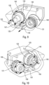
- the pinching of the tube(s) 145 is preferably carried out by cam means formed on a moving part, in particular a rotating member.
- THE figures 30 to 37 show another embodiment.
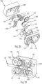
- the selection wheel is replaced by a rotating selection shaft 135, supporting several cam elements 1350, three in the example shown.
- a pinching member 1360 is provided between said cam elements 1350 and the tubes 145.
- This pinching member 1360 advantageously comprises flexible blades, one for each tube 145, which are elastically deformed by the cam elements 1350 of the selection shaft 135. This avoids friction cam elements on the tubes, which can have the disadvantage of deforming them and making the pinching less effective.
- THE figures 32 and 35 show an unpinched tube 145, with consequently a circulation of fluid in said tube 145 which is possible, whereas the figures 33 and 34 show a tube 145 pinched or crushed by a blade of the pinching member 1360, itself pushed by a cam element 1350 of the selection shaft 135, with therefore no possible circulation of fluid.
- figures 38 to 41 is very similar to that of the figures 30 to 37 , with the three tanks which are arranged side by side, as illustrated in the figure 39 by the three priming needles 125 arranged in parallel in the same plane.
- the pinching member 1360 forms a single piece, but alternatively, several separate pinching members could be provided, each formed by a flexible blade.
- the distribution system preferably comprises a peristaltic pump.
- This comprises a ring 150 which rotates on a crankshaft 131 around an axis of rotation Y offset from the axis of rotation X of said crankshaft 131.
- the rotation axis X of the crankshaft 131 is formed by a central axial cylinder 1310, around which the ring 150 can rotate.
- a tube portion 148 which goes from the manifold 140 to the injection needle 120 extends around said crankshaft 131, such that the ring 150, as it rotates around its offset rotation axis Y, will rotate around said central axial cylinder 1310 of the crankshaft 131 by moving the compression along the tube 148, thus generating the distribution of the fluid product which passes into said tube 148.
- figures 19 to 21 illustrate the operation of the peristaltic pump.
Landscapes
- Health & Medical Sciences (AREA)
- Heart & Thoracic Surgery (AREA)
- Animal Behavior & Ethology (AREA)
- General Health & Medical Sciences (AREA)
- Biomedical Technology (AREA)
- Engineering & Computer Science (AREA)
- Hematology (AREA)
- Life Sciences & Earth Sciences (AREA)
- Veterinary Medicine (AREA)
- Anesthesiology (AREA)
- Public Health (AREA)
- Vascular Medicine (AREA)
- Pulmonology (AREA)
- Dermatology (AREA)
- Infusion, Injection, And Reservoir Apparatuses (AREA)
- Reciprocating Pumps (AREA)
Claims (14)
- Injektionsvorrichtung für ein Fluidprodukt, aufweisend einen Körper, der dazu bestimmt ist, mit einer Injektionsstelle (SI) in Kontakt zu kommen, mindestens zwei Vorratsbehälter (210) für Fluidprodukt, eine Injektionsnadel (120), die dazu bestimmt ist, in die Injektionsstelle (SI) einzudringen, um dort den Inhalt eines oder mehrerer Vorratsbehälter (210) zu injizieren, wobei die Vorrichtung einen einzigen drehbaren Aktuator (130) aufweist, der, wenn er in einer ersten Drehrichtung dreht, Mittel aufweist, um die Auswahl des oder der abzugebenden Vorratsbehälter (210) zu betätigen, und der, wenn er in der umgekehrten Richtung dreht, Mittel aufweist, um ein Abgabesystem zu betätigen, insbesondere eine peristaltische Pumpe (150), dadurch gekennzeichnet, dass der Aktuator (130) eine Mittelachse (1300) aufweist, die sich in einer länglichen Öffnung (1500) des Körpers erstreckt, somit ein Losrad bildet, wobei der Aktuator (130), wenn er auf einer ersten Seite der länglichen Öffnung (1500) ist, mit einer Zahnung eines drehenden Wählorgans (132, 135) zusammenwirkt, insbesondere über ein Zwischenrad (133), um die Auswahl des oder der abzugebenden Vorratsbehälter zu betätigen, und der, wenn er auf der anderen Seite der länglichen Öffnung (1500) ist, mit einer Zahnung einer Kurbelwelle (131) zusammenwirkt, um eine peristaltische Pumpe zu betätigen.
- Vorrichtung nach Anspruch 1, wobei eine Starternadel (125) jedem Vorratsbehälter (210) zugeordnet ist und dazu bestimmt, vor der Abgabe des Fluidprodukts in den Vorratsbehälter (210) einzudringen, wobei jeder Vorratsbehälter (210) einen Schlauch (145) umfasst, der auf der einen Seite mit seiner jeweiligen Starternadel (125) und auf der anderen Seite mit einem Sammler (140) verbunden ist, der selbst mit der Injektionsnadel mittels eines Schlauchabschnitts (148) verbunden ist.
- Vorrichtung nach Anspruch 2, aufweisend Vorratsbehälterauswahlmittel, um einen oder mehrere Vorratsbehälter (210) auszuwählen, deren Inhalt bei der nächsten Betätigung abgegeben wird, wobei die Auswahlmittel ein drehbares Organ (132, 135) umfassen, das mit Nockenmitteln (1320, 1350) versehen ist, die geeignet sind, mit den Schläuchen (145) jedes Vorratsbehälters (210) zusammenzuwirken, um den Fluidstrom durch jeden Schlauch (145) freizugeben oder zu schließen.
- Vorrichtung nach Anspruch 3, wobei das drehbare Organ ein mit einem Nocken (1320) versehenes Wählrad (132) ist.
- Vorrichtung nach Anspruch 4, wobei der Nocken (1320) durch einen bogenförmigen Vorsprung gebildet ist, wobei der Nocken (1320) durch mindestens eine Aussparung (1321) unterbrochen ist, so dass, wenn der Nocken (1320) mit einem Schlauch (145) in Kontakt ist, er diesen einklemmt, um den Fluidfluss zu unterbrechen, und wenn ein Schlauch (145) der Aussparung (1321) gegenüberliegt, der Fluidfluss möglich ist.
- Vorrichtung nach Anspruch 4, wobei der Nocken (1320) radial in einem Mittelloch (1325) des Wählrads (132) ausgebildet ist, wobei die Schläuche (145) durch das Mittelloch (1325) verlaufen, wobei der Nocken (1320) einen Abschnitt mit größerem Durchmesser (1321) aufweist, so dass, wenn ein Schlauch (145) mit dem Nocken (1320) zusammenwirkt, er eingeklemmt wird, und wenn ein Schlauch (145) mit dem Abschnitt mit größerem Durchmesser (1321) zusammenwirkt, er nicht eingeklemmt wird.
- Vorrichtung nach Anspruch 3, wobei das drehbare Organ eine mit Nockenelementen (1350) versehene Welle (135) ist.
- Vorrichtung nach Anspruch 7, wobei die Nockenelemente (1350) mit einem Klemmorgan (1360) zusammenwirken, das mit mehreren flexiblen Klingen versehen ist, eine für jeden Vorratsbehälterschlauch (145), so dass, wenn ein Nockenelement (1350) eine flexible Klinge des Klemmorgans verformt, diese ihren jeweiligen Schlauch (145) einklemmt, um den Fluidfluss zu unterbrechen.
- Vorrichtung nach einem der Ansprüche 2 bis 8, wobei das Abgabesystem eine peristaltische Pumpe aufweist, die einen Ring (150) umfasst, der drehbar auf einer Kurbelwelle (131) angebracht ist, wobei sich der Ring (150) um eine Drehachse (Y) dreht, die zur Drehachse (X) der Kurbelwelle (131) versetzt ist, indem er einen Schlauchabschnitt (148), der sich um die Kurbelwelle (131) herum erstreckt, allmählich zusammendrückt.
- Vorrichtung nach Anspruch 8, wobei sich der Ring (150) um einen zentralen Zylinder (1310) der Kurbelwelle (131) dreht.
- Vorrichtung nach einem der vorhergehenden Ansprüche, wobei jeder Vorratsbehälter zwischen 1 und 10 ml, in vorteilhafter Weise etwa 3 ml, eines Fluidprodukts enthält.
- Vorrichtung nach einem der vorhergehenden Ansprüche, wobei die Vorrichtung ein elektronisches Modul (300) aufweist.
- Vorrichtung nach Anspruch 12, wobei das elektronische Modul (300) eine Stromversorgung, insbesondere eine Batterie oder einen Akkumulator, einen Mikroprozessor, Speichermittel, Mittel zum Empfangen und/oder Senden von Signalen und einen Motor umfasst.
- Vorrichtung nach Anspruch 12 oder 13, wobei das elektronische Modul (300) wiederverwendbar ist und abnehmbar an der Vorrichtung befestigt ist.
Applications Claiming Priority (2)
| Application Number | Priority Date | Filing Date | Title |
|---|---|---|---|
| FR1856496A FR3083708B1 (fr) | 2018-07-13 | 2018-07-13 | Dispositif d'injection de produit fluide. |
| PCT/FR2019/051746 WO2020012132A1 (fr) | 2018-07-13 | 2019-07-11 | Dispositif d'injection de produit fluide |
Publications (2)
| Publication Number | Publication Date |
|---|---|
| EP3820547A1 EP3820547A1 (de) | 2021-05-19 |
| EP3820547B1 true EP3820547B1 (de) | 2025-04-09 |
Family
ID=63722597
Family Applications (1)
| Application Number | Title | Priority Date | Filing Date |
|---|---|---|---|
| EP19756220.0A Active EP3820547B1 (de) | 2018-07-13 | 2019-07-11 | Einspritzvorrichtung für flüssigkeiten |
Country Status (5)
| Country | Link |
|---|---|
| US (1) | US12508358B2 (de) |
| EP (1) | EP3820547B1 (de) |
| JP (1) | JP7465254B2 (de) |
| FR (1) | FR3083708B1 (de) |
| WO (1) | WO2020012132A1 (de) |
Families Citing this family (6)
| Publication number | Priority date | Publication date | Assignee | Title |
|---|---|---|---|---|
| ATE480278T1 (de) | 2005-09-12 | 2010-09-15 | Unomedical As | Einfürungssystem für ein infusionsset mit einem ersten und zweiten federeinheit |
| US10194938B2 (en) | 2011-03-14 | 2019-02-05 | UnoMedical, AS | Inserter system with transport protection |
| CA3141608A1 (en) | 2019-05-20 | 2020-11-26 | Unomedical A/S | Rotatable infusion device and methods thereof |
| FR3109318B1 (fr) * | 2020-04-15 | 2023-11-10 | Syrengy | Seringue d’injection |
| CA3216453A1 (en) | 2021-04-23 | 2022-10-27 | Unomedical A/S | Miniaturized patch pump system |
| WO2023237357A1 (en) * | 2022-06-09 | 2023-12-14 | Shl Medical Ag | Drug delivery control arrangement, and injector |
Family Cites Families (15)
| Publication number | Priority date | Publication date | Assignee | Title |
|---|---|---|---|---|
| ZA78674B (en) * | 1978-02-09 | 1979-09-26 | Ethor Ltd | Dispensing of fluent materials |
| AR244863A1 (es) * | 1989-09-07 | 1993-11-30 | Marcelo Alberto Hoegner | Una valvula multiple y un equipo de esterilizacion que la incorpora. |
| EP1682203B1 (de) | 2003-10-23 | 2010-01-06 | Novo Nordisk A/S | Auf der haut befestigbare medizinische injektionsvorrichtung |
| US7905868B2 (en) | 2006-08-23 | 2011-03-15 | Medtronic Minimed, Inc. | Infusion medium delivery device and method with drive device for driving plunger in reservoir |
| US20070088271A1 (en) | 2005-10-18 | 2007-04-19 | Richards Cynthia C | Medication device |
| US9114243B2 (en) * | 2009-02-19 | 2015-08-25 | Covidien Lp | Manual valve actuator for medical fluid delivery set |
| US8382447B2 (en) * | 2009-12-31 | 2013-02-26 | Baxter International, Inc. | Shuttle pump with controlled geometry |
| EP2646077B1 (de) | 2010-11-29 | 2015-06-24 | Sanofi-Aventis Deutschland GmbH | Spenderschnittstellenkomponente für eine arzneimittelverabreichungsvorrichtung |
| DK2714135T3 (da) | 2011-05-25 | 2023-02-06 | Sanofi Aventis Deutschland | Medikamentadministrationsanordning og fremgangsmåde til styring af anordningen |
| AU2012336378B2 (en) * | 2011-11-08 | 2018-03-15 | David R. Duncan | Compact non-electric medicament infuser |
| JP2014012123A (ja) | 2012-06-06 | 2014-01-23 | Nidec Copal Electronics Corp | 輸液ポンプ用カセットおよび輸液ポンプ |
| JP6650241B2 (ja) | 2015-10-13 | 2020-02-19 | 日立グローバルライフソリューションズ株式会社 | 洗濯機 |
| CA2947713A1 (en) * | 2015-11-06 | 2017-05-06 | Teleflex Medical Incorporated | Valve apparatus that regulates flow of fluid and vacuum pressure |
| JP5938137B1 (ja) | 2015-12-15 | 2016-06-22 | プライムテック株式会社 | 流体切替弁および流体輸送カートリッジ |
| WO2018067734A1 (en) | 2016-10-04 | 2018-04-12 | Craig M D H Randall | Medication delivery method and device with remote control |
-
2018
- 2018-07-13 FR FR1856496A patent/FR3083708B1/fr active Active
-
2019
- 2019-07-11 US US17/259,832 patent/US12508358B2/en active Active
- 2019-07-11 JP JP2021500914A patent/JP7465254B2/ja active Active
- 2019-07-11 WO PCT/FR2019/051746 patent/WO2020012132A1/fr not_active Ceased
- 2019-07-11 EP EP19756220.0A patent/EP3820547B1/de active Active
Also Published As
| Publication number | Publication date |
|---|---|
| EP3820547A1 (de) | 2021-05-19 |
| JP2021524348A (ja) | 2021-09-13 |
| JP7465254B2 (ja) | 2024-04-10 |
| FR3083708A1 (fr) | 2020-01-17 |
| US20220193332A1 (en) | 2022-06-23 |
| WO2020012132A1 (fr) | 2020-01-16 |
| US12508358B2 (en) | 2025-12-30 |
| FR3083708B1 (fr) | 2023-12-08 |
Similar Documents
| Publication | Publication Date | Title |
|---|---|---|
| EP3820547B1 (de) | Einspritzvorrichtung für flüssigkeiten | |
| EP3582824B1 (de) | Automatische injektionsvorrichtung für fluidprodukte | |
| EP0605673B1 (de) | Reibungsfreie infusionspumpe | |
| EP0323321B1 (de) | Spritzenpumpe | |
| EP3648900B1 (de) | Spender für ein flüssigprodukt | |
| EP2310140A1 (de) | Fluidproduktabgabevorrichtung | |
| FR2767479A1 (fr) | Dispositif d'injection de medicament | |
| EP3820546B1 (de) | Einspritzvorrichtung für flüssigkeiten | |
| EP3615107B1 (de) | Automatische injektionsvorrichtung für fluidprodukte | |
| EP3820545B1 (de) | Fluidproduktinjektionsvorrichtung | |
| EP4283124B1 (de) | Verbesserte peristaltische pumpe | |
| EP3302646B1 (de) | Autoinjektor mit einer verzögerungsvorrichtung mit einem planetengetriebe | |
| EP0932423B1 (de) | Miniaturisierte peristaltikpumpe zur medizinischen anwendung | |
| EP4225401B1 (de) | System und vorrichtung zur ausgabe eines produkts | |
| FR3142677A3 (fr) | Dispositif d’administration sous-cutanée d’un médicament | |
| FR3142678A3 (fr) | Dispositif d’administration sous-cutanée d’un médicament | |
| FR3142675A3 (fr) | Dispositif d’administration sous-cutanée d’un médicament | |
| FR3142674A3 (fr) | Dispositif d’administration sous-cutanée d’un médicament | |
| FR3134726A1 (fr) | Système d’activation pour dispositif d’administration de médicament transdermique | |
| FR3134727A1 (fr) | Système d’injection amélioré pour dispositif d’administration de médicament transdermique | |
| FR3142676A3 (fr) | Dispositif d’administration sous-cutanée d’un médicament | |
| EP4719545A1 (de) | Vorrichtung zur abgabe eines flüssigen produkts |
Legal Events
| Date | Code | Title | Description |
|---|---|---|---|
| STAA | Information on the status of an ep patent application or granted ep patent |
Free format text: STATUS: UNKNOWN |
|
| STAA | Information on the status of an ep patent application or granted ep patent |
Free format text: STATUS: THE INTERNATIONAL PUBLICATION HAS BEEN MADE |
|
| PUAI | Public reference made under article 153(3) epc to a published international application that has entered the european phase |
Free format text: ORIGINAL CODE: 0009012 |
|
| STAA | Information on the status of an ep patent application or granted ep patent |
Free format text: STATUS: REQUEST FOR EXAMINATION WAS MADE |
|
| 17P | Request for examination filed |
Effective date: 20210210 |
|
| AK | Designated contracting states |
Kind code of ref document: A1 Designated state(s): AL AT BE BG CH CY CZ DE DK EE ES FI FR GB GR HR HU IE IS IT LI LT LU LV MC MK MT NL NO PL PT RO RS SE SI SK SM TR |
|
| DAV | Request for validation of the european patent (deleted) | ||
| DAX | Request for extension of the european patent (deleted) | ||
| STAA | Information on the status of an ep patent application or granted ep patent |
Free format text: STATUS: EXAMINATION IS IN PROGRESS |
|
| 17Q | First examination report despatched |
Effective date: 20211119 |
|
| GRAP | Despatch of communication of intention to grant a patent |
Free format text: ORIGINAL CODE: EPIDOSNIGR1 |
|
| STAA | Information on the status of an ep patent application or granted ep patent |
Free format text: STATUS: GRANT OF PATENT IS INTENDED |
|
| INTG | Intention to grant announced |
Effective date: 20241114 |
|
| P01 | Opt-out of the competence of the unified patent court (upc) registered |
Free format text: CASE NUMBER: APP_122/2025 Effective date: 20250102 |
|
| GRAS | Grant fee paid |
Free format text: ORIGINAL CODE: EPIDOSNIGR3 |
|
| GRAA | (expected) grant |
Free format text: ORIGINAL CODE: 0009210 |
|
| STAA | Information on the status of an ep patent application or granted ep patent |
Free format text: STATUS: THE PATENT HAS BEEN GRANTED |
|
| AK | Designated contracting states |
Kind code of ref document: B1 Designated state(s): AL AT BE BG CH CY CZ DE DK EE ES FI FR GB GR HR HU IE IS IT LI LT LU LV MC MK MT NL NO PL PT RO RS SE SI SK SM TR |
|
| REG | Reference to a national code |
Ref country code: GB Ref legal event code: FG4D Free format text: NOT ENGLISH |
|
| REG | Reference to a national code |
Ref country code: CH Ref legal event code: EP |
|
| REG | Reference to a national code |
Ref country code: DE Ref legal event code: R096 Ref document number: 602019068428 Country of ref document: DE |
|
| REG | Reference to a national code |
Ref country code: IE Ref legal event code: FG4D Free format text: LANGUAGE OF EP DOCUMENT: FRENCH |
|
| REG | Reference to a national code |
Ref country code: NL Ref legal event code: MP Effective date: 20250409 |
|
| PG25 | Lapsed in a contracting state [announced via postgrant information from national office to epo] |
Ref country code: NL Free format text: LAPSE BECAUSE OF FAILURE TO SUBMIT A TRANSLATION OF THE DESCRIPTION OR TO PAY THE FEE WITHIN THE PRESCRIBED TIME-LIMIT Effective date: 20250409 |
|
| REG | Reference to a national code |
Ref country code: AT Ref legal event code: MK05 Ref document number: 1782996 Country of ref document: AT Kind code of ref document: T Effective date: 20250409 |
|
| PG25 | Lapsed in a contracting state [announced via postgrant information from national office to epo] |
Ref country code: FI Free format text: LAPSE BECAUSE OF FAILURE TO SUBMIT A TRANSLATION OF THE DESCRIPTION OR TO PAY THE FEE WITHIN THE PRESCRIBED TIME-LIMIT Effective date: 20250409 Ref country code: ES Free format text: LAPSE BECAUSE OF FAILURE TO SUBMIT A TRANSLATION OF THE DESCRIPTION OR TO PAY THE FEE WITHIN THE PRESCRIBED TIME-LIMIT Effective date: 20250409 Ref country code: PT Free format text: LAPSE BECAUSE OF FAILURE TO SUBMIT A TRANSLATION OF THE DESCRIPTION OR TO PAY THE FEE WITHIN THE PRESCRIBED TIME-LIMIT Effective date: 20250811 |
|
| PGFP | Annual fee paid to national office [announced via postgrant information from national office to epo] |
Ref country code: DE Payment date: 20250711 Year of fee payment: 7 |
|
| REG | Reference to a national code |
Ref country code: LT Ref legal event code: MG9D |
|
| PG25 | Lapsed in a contracting state [announced via postgrant information from national office to epo] |
Ref country code: GR Free format text: LAPSE BECAUSE OF FAILURE TO SUBMIT A TRANSLATION OF THE DESCRIPTION OR TO PAY THE FEE WITHIN THE PRESCRIBED TIME-LIMIT Effective date: 20250710 Ref country code: NO Free format text: LAPSE BECAUSE OF FAILURE TO SUBMIT A TRANSLATION OF THE DESCRIPTION OR TO PAY THE FEE WITHIN THE PRESCRIBED TIME-LIMIT Effective date: 20250709 |
|
| PG25 | Lapsed in a contracting state [announced via postgrant information from national office to epo] |
Ref country code: PL Free format text: LAPSE BECAUSE OF FAILURE TO SUBMIT A TRANSLATION OF THE DESCRIPTION OR TO PAY THE FEE WITHIN THE PRESCRIBED TIME-LIMIT Effective date: 20250409 |
|
| PGFP | Annual fee paid to national office [announced via postgrant information from national office to epo] |
Ref country code: IT Payment date: 20250708 Year of fee payment: 7 |
|
| PG25 | Lapsed in a contracting state [announced via postgrant information from national office to epo] |
Ref country code: BG Free format text: LAPSE BECAUSE OF FAILURE TO SUBMIT A TRANSLATION OF THE DESCRIPTION OR TO PAY THE FEE WITHIN THE PRESCRIBED TIME-LIMIT Effective date: 20250409 |
|
| PGFP | Annual fee paid to national office [announced via postgrant information from national office to epo] |
Ref country code: GB Payment date: 20250723 Year of fee payment: 7 |
|
| PG25 | Lapsed in a contracting state [announced via postgrant information from national office to epo] |
Ref country code: HR Free format text: LAPSE BECAUSE OF FAILURE TO SUBMIT A TRANSLATION OF THE DESCRIPTION OR TO PAY THE FEE WITHIN THE PRESCRIBED TIME-LIMIT Effective date: 20250409 |
|
| PG25 | Lapsed in a contracting state [announced via postgrant information from national office to epo] |
Ref country code: AT Free format text: LAPSE BECAUSE OF FAILURE TO SUBMIT A TRANSLATION OF THE DESCRIPTION OR TO PAY THE FEE WITHIN THE PRESCRIBED TIME-LIMIT Effective date: 20250409 |
|
| PGFP | Annual fee paid to national office [announced via postgrant information from national office to epo] |
Ref country code: FR Payment date: 20250730 Year of fee payment: 7 |
|
| PG25 | Lapsed in a contracting state [announced via postgrant information from national office to epo] |
Ref country code: RS Free format text: LAPSE BECAUSE OF FAILURE TO SUBMIT A TRANSLATION OF THE DESCRIPTION OR TO PAY THE FEE WITHIN THE PRESCRIBED TIME-LIMIT Effective date: 20250709 |
|
| PG25 | Lapsed in a contracting state [announced via postgrant information from national office to epo] |
Ref country code: IS Free format text: LAPSE BECAUSE OF FAILURE TO SUBMIT A TRANSLATION OF THE DESCRIPTION OR TO PAY THE FEE WITHIN THE PRESCRIBED TIME-LIMIT Effective date: 20250809 |
|
| PG25 | Lapsed in a contracting state [announced via postgrant information from national office to epo] |
Ref country code: LV Free format text: LAPSE BECAUSE OF FAILURE TO SUBMIT A TRANSLATION OF THE DESCRIPTION OR TO PAY THE FEE WITHIN THE PRESCRIBED TIME-LIMIT Effective date: 20250409 |
|
| REG | Reference to a national code |
Ref country code: DE Ref legal event code: R097 Ref document number: 602019068428 Country of ref document: DE |
|
| PG25 | Lapsed in a contracting state [announced via postgrant information from national office to epo] |
Ref country code: DK Free format text: LAPSE BECAUSE OF FAILURE TO SUBMIT A TRANSLATION OF THE DESCRIPTION OR TO PAY THE FEE WITHIN THE PRESCRIBED TIME-LIMIT Effective date: 20250409 Ref country code: SM Free format text: LAPSE BECAUSE OF FAILURE TO SUBMIT A TRANSLATION OF THE DESCRIPTION OR TO PAY THE FEE WITHIN THE PRESCRIBED TIME-LIMIT Effective date: 20250409 |
|
| PG25 | Lapsed in a contracting state [announced via postgrant information from national office to epo] |
Ref country code: CZ Free format text: LAPSE BECAUSE OF FAILURE TO SUBMIT A TRANSLATION OF THE DESCRIPTION OR TO PAY THE FEE WITHIN THE PRESCRIBED TIME-LIMIT Effective date: 20250409 |
|
| PG25 | Lapsed in a contracting state [announced via postgrant information from national office to epo] |
Ref country code: EE Free format text: LAPSE BECAUSE OF FAILURE TO SUBMIT A TRANSLATION OF THE DESCRIPTION OR TO PAY THE FEE WITHIN THE PRESCRIBED TIME-LIMIT Effective date: 20250409 |
|
| PG25 | Lapsed in a contracting state [announced via postgrant information from national office to epo] |
Ref country code: RO Free format text: LAPSE BECAUSE OF FAILURE TO SUBMIT A TRANSLATION OF THE DESCRIPTION OR TO PAY THE FEE WITHIN THE PRESCRIBED TIME-LIMIT Effective date: 20250409 Ref country code: SK Free format text: LAPSE BECAUSE OF FAILURE TO SUBMIT A TRANSLATION OF THE DESCRIPTION OR TO PAY THE FEE WITHIN THE PRESCRIBED TIME-LIMIT Effective date: 20250409 |
|
| PLBE | No opposition filed within time limit |
Free format text: ORIGINAL CODE: 0009261 |
|
| STAA | Information on the status of an ep patent application or granted ep patent |
Free format text: STATUS: NO OPPOSITION FILED WITHIN TIME LIMIT |
|
| REG | Reference to a national code |
Ref country code: CH Ref legal event code: L10 Free format text: ST27 STATUS EVENT CODE: U-0-0-L10-L00 (AS PROVIDED BY THE NATIONAL OFFICE) Effective date: 20260218 |
|
| REG | Reference to a national code |
Ref country code: CH Ref legal event code: H13 Free format text: ST27 STATUS EVENT CODE: U-0-0-H10-H13 (AS PROVIDED BY THE NATIONAL OFFICE) Effective date: 20260224 |
|
| PG25 | Lapsed in a contracting state [announced via postgrant information from national office to epo] |
Ref country code: LU Free format text: LAPSE BECAUSE OF NON-PAYMENT OF DUE FEES Effective date: 20250711 |
|
| 26N | No opposition filed |
Effective date: 20260112 |
|
| REG | Reference to a national code |
Ref country code: BE Ref legal event code: MM Effective date: 20250731 |
|
| PG25 | Lapsed in a contracting state [announced via postgrant information from national office to epo] |
Ref country code: BE Free format text: LAPSE BECAUSE OF NON-PAYMENT OF DUE FEES Effective date: 20250731 |
|
| PG25 | Lapsed in a contracting state [announced via postgrant information from national office to epo] |
Ref country code: CH Free format text: LAPSE BECAUSE OF NON-PAYMENT OF DUE FEES Effective date: 20250731 |