EP3820559B1 - Platzierungssystem für implantierbaren port mit aussenteil mit niedriger vernarbung - Google Patents
Platzierungssystem für implantierbaren port mit aussenteil mit niedriger vernarbung Download PDFInfo
- Publication number
- EP3820559B1 EP3820559B1 EP19844795.5A EP19844795A EP3820559B1 EP 3820559 B1 EP3820559 B1 EP 3820559B1 EP 19844795 A EP19844795 A EP 19844795A EP 3820559 B1 EP3820559 B1 EP 3820559B1
- Authority
- EP
- European Patent Office
- Prior art keywords
- port
- stem
- access port
- placement tool
- port system
- Prior art date
- Legal status (The legal status is an assumption and is not a legal conclusion. Google has not performed a legal analysis and makes no representation as to the accuracy of the status listed.)
- Active
Links
Images








Classifications
-
- A—HUMAN NECESSITIES
- A61—MEDICAL OR VETERINARY SCIENCE; HYGIENE
- A61M—DEVICES FOR INTRODUCING MEDIA INTO, OR ONTO, THE BODY; DEVICES FOR TRANSDUCING BODY MEDIA OR FOR TAKING MEDIA FROM THE BODY; DEVICES FOR PRODUCING OR ENDING SLEEP OR STUPOR
- A61M39/00—Tubes, tube connectors, tube couplings, valves, access sites or the like, specially adapted for medical use
- A61M39/02—Access sites
- A61M39/0208—Subcutaneous access sites for injecting or removing fluids
-
- A—HUMAN NECESSITIES
- A61—MEDICAL OR VETERINARY SCIENCE; HYGIENE
- A61M—DEVICES FOR INTRODUCING MEDIA INTO, OR ONTO, THE BODY; DEVICES FOR TRANSDUCING BODY MEDIA OR FOR TAKING MEDIA FROM THE BODY; DEVICES FOR PRODUCING OR ENDING SLEEP OR STUPOR
- A61M39/00—Tubes, tube connectors, tube couplings, valves, access sites or the like, specially adapted for medical use
- A61M2039/0036—Tubes, tube connectors, tube couplings, valves, access sites or the like, specially adapted for medical use characterised by a septum having particular features, e.g. having venting channels or being made from antimicrobial or self-lubricating elastomer
- A61M2039/0045—Radiopaque indicia
-
- A—HUMAN NECESSITIES
- A61—MEDICAL OR VETERINARY SCIENCE; HYGIENE
- A61M—DEVICES FOR INTRODUCING MEDIA INTO, OR ONTO, THE BODY; DEVICES FOR TRANSDUCING BODY MEDIA OR FOR TAKING MEDIA FROM THE BODY; DEVICES FOR PRODUCING OR ENDING SLEEP OR STUPOR
- A61M39/00—Tubes, tube connectors, tube couplings, valves, access sites or the like, specially adapted for medical use
- A61M2039/0036—Tubes, tube connectors, tube couplings, valves, access sites or the like, specially adapted for medical use characterised by a septum having particular features, e.g. having venting channels or being made from antimicrobial or self-lubricating elastomer
- A61M2039/0072—Means for increasing tightness of the septum, e.g. compression rings, special materials, special constructions
-
- A—HUMAN NECESSITIES
- A61—MEDICAL OR VETERINARY SCIENCE; HYGIENE
- A61M—DEVICES FOR INTRODUCING MEDIA INTO, OR ONTO, THE BODY; DEVICES FOR TRANSDUCING BODY MEDIA OR FOR TAKING MEDIA FROM THE BODY; DEVICES FOR PRODUCING OR ENDING SLEEP OR STUPOR
- A61M39/00—Tubes, tube connectors, tube couplings, valves, access sites or the like, specially adapted for medical use
- A61M39/02—Access sites
- A61M39/0208—Subcutaneous access sites for injecting or removing fluids
- A61M2039/0232—Subcutaneous access sites for injecting or removing fluids having means for facilitating the insertion into the body
-
- A—HUMAN NECESSITIES
- A61—MEDICAL OR VETERINARY SCIENCE; HYGIENE
- A61M—DEVICES FOR INTRODUCING MEDIA INTO, OR ONTO, THE BODY; DEVICES FOR TRANSDUCING BODY MEDIA OR FOR TAKING MEDIA FROM THE BODY; DEVICES FOR PRODUCING OR ENDING SLEEP OR STUPOR
- A61M39/00—Tubes, tube connectors, tube couplings, valves, access sites or the like, specially adapted for medical use
- A61M39/02—Access sites
- A61M39/0208—Subcutaneous access sites for injecting or removing fluids
- A61M2039/0238—Subcutaneous access sites for injecting or removing fluids having means for locating the implanted device to insure proper injection, e.g. radio-emitter, protuberances, radio-opaque markers
-
- A—HUMAN NECESSITIES
- A61—MEDICAL OR VETERINARY SCIENCE; HYGIENE
- A61M—DEVICES FOR INTRODUCING MEDIA INTO, OR ONTO, THE BODY; DEVICES FOR TRANSDUCING BODY MEDIA OR FOR TAKING MEDIA FROM THE BODY; DEVICES FOR PRODUCING OR ENDING SLEEP OR STUPOR
- A61M39/00—Tubes, tube connectors, tube couplings, valves, access sites or the like, specially adapted for medical use
- A61M39/02—Access sites
- A61M39/0247—Semi-permanent or permanent transcutaneous or percutaneous access sites to the inside of the body
- A61M2039/0291—Semi-permanent or permanent transcutaneous or percutaneous access sites to the inside of the body method or device for implanting it in the body
-
- A—HUMAN NECESSITIES
- A61—MEDICAL OR VETERINARY SCIENCE; HYGIENE
- A61M—DEVICES FOR INTRODUCING MEDIA INTO, OR ONTO, THE BODY; DEVICES FOR TRANSDUCING BODY MEDIA OR FOR TAKING MEDIA FROM THE BODY; DEVICES FOR PRODUCING OR ENDING SLEEP OR STUPOR
- A61M5/00—Devices for bringing media into the body in a subcutaneous, intra-vascular or intramuscular way; Accessories therefor, e.g. filling or cleaning devices, arm-rests
- A61M5/14—Infusion devices, e.g. infusing by gravity; Blood infusion; Accessories therefor
- A61M5/142—Pressure infusion, e.g. using pumps
- A61M5/14244—Pressure infusion, e.g. using pumps adapted to be carried by the patient, e.g. portable on the body
- A61M5/14276—Pressure infusion, e.g. using pumps adapted to be carried by the patient, e.g. portable on the body specially adapted for implantation
Definitions
- port Current implantable access port placement involves a multi-step process requiring a scalpel to form an incision, a Kelly clamp or similar device for blunt dissection of the subcutaneous tissues to form a tissue pocket, repeated insertion of the port to ensure a snug fit, placing the port, and lastly closing the incision.
- the repeated insertion of the port is often necessary to ensure the tissue pocket is sufficiently large enough to receive the port, while at the same time is not too large so as to prevent the port traveling or inverting after it has been placed.
- septum thickness needs to be sufficient to prevent rupturing when contrast fluid is introduced under pressure.
- the configuration of Huber-type, non-coring access needles with sufficient lumen diameter to provide the necessary flow rate, e.g., at least about 1 milliliter per second, results in an extended needle bevel to accommodate the lumen opening. Accordingly, the reservoir depth is also required to be sufficient to fit the entire needle bevel into the reservoir. If the needle bevel is not entirely within the reservoir, the contrast fluid can escape to the surrounding tissues, and is detrimental to the patients' health.
- the combined effect of these two factors demand power injection ports to have a relatively large transverse profiles. Accordingly, implanting such ports requires substantial stretching of incision site and the surrounding tissues, inducing scarring.
- the placement system including a placement tool and a port, simultaneously forms an incision, dissect tissue, create a tissue pocket of the correct size for the port being placed, and place the port subcutaneously. This results in reduced procedure times, reduced scarring, and minimized wound management.
- the port includes features that allow for a low overall profile, while still capable of withstanding power injection. Thus reducing tension on the tissue pocket and incision site, reducing potential scarring.
- US 2009/0259187 A1 relates to a port catheter for introducing a fluid into a hollow organ of a human or animal body including a port unit implantable into the human or animal body, which port unit includes an interior chamber, to which the fluid to be introduced into the hollow organ of the human or animal body can be supplied.
- EP 1 736 202 A1 relates to an attachment mechanism for a surgically implantable medical device including one or more fasteners which may be simultaneously moved from an undeployed position to a deployed position by operation of an integral actuator.
- US 2011/0054407 A1 relates to a system for attaching a fluid access port to a patient.
- EP 0 260 080 A2 relates to an instrument for subcutaneously inserting an injection reservoir attached to an inflatable prosthesis by means of an elongated fluid conduit.
- WO 2005/037055 A2 relates to a surgical fastening system for implantable devices.
- Embodiments of the present invention are generally directed to an implantable access port configured to provide needle access to a vasculature of a patient for the delivery of medicaments or the like.
- the access port is shaped and configured to minimize scarring to a patient after the port has been subcutaneously implanted.
- a subcutaneous access port system comprising of a placement tool including a proximal handle and a distal port holder, and an implantable access port releasably secured to the port holder, the port comprising of a housing including a base and a reservoir, a needle-penetrable septum covering the reservoir, and a body coupled to the housing over the needle-penetrable septum, the body comprising of a stem cover configured to engage the distal port holder, and a tunneling edge opposite of the stem cover sharpened to facilitate dissection of the tissue as the implantable access port is urged subcutaneously.
- the subcutaneous access port system further comprises an indicia marker, the indicia marker disposed between the base and the body.
- the indicia marker is radiopaque and includes one of an alphanumeric symbol and shape denoting one of a feature and an orientation of the port.
- the placement tool engages an outer surface of the stem cover.
- the placement tool engages one of an inner surface of the stem cover, an end surface of the stem cover, and a stem aperture of the housing, the stem aperture also configured for receiving a stem portion, the stem portion providing fluid communication between the reservoir and a catheter attached thereto.
- the stem cover includes one of a protrusion, a detent, and a socket, configured to engage the placement tool.
- the body further includes a skive on a side surface thereof, the skive defining a tapered footprint of the distal portion of the body.
- the septum defines a convex upper surface to allow a needle to access the reservoir at an acute angle relative to a skin surface of the patient.
- a vertical depth of the reservoir is less than a maximum length of a bevel of an access needle, accessing the port.
- a footprint shape of the port includes one of a circular, crescent, reniform, elongate balloon and arrow shape.
- the septum includes a reinforcement.
- the reinforcement includes one of a wire reinforcement and a matrix reinforcement.
- the reinforcement includes a wire mesh.
- the reinforcement includes a plurality of individual wire strands, and one of the individual wire strands extends through a center-point of the septum.
- the reinforcement includes a matrix of silicone rubber with one of a plurality of particles and a plurality of fibers disposed therein.
- the plurality of particles are formed of one or more of a metal, a ceramic, and a polymer, and the particles range in size from 10 nm to 1.0 mm in diameter.
- the plurality of fibers are formed of one or more of a metal, a ceramic, and a polymer, and the fibers range in length from 1 mm and 15 mm in diameter.
- a system for placing an implantable port comprising of a port; and a placement tool, comprising of an elongate body including a handle, a port holder disposed at a distal end of the elongate body and configured to releasably secure the port thereto, the port holder including a base, a curved panel, and a tunneling edge, and an actuator configured for selectively releasing the port.
- the base defines a perimeter, the shape of the perimeter matching the shape of a footprint of the port.
- the base and the curved panel define a recess, the recess configured to receive a distal portion of the port.
- the tunneling edge is sharpened and configured to dissect tissue when the placement tool is urged subcutaneously.
- the curved panel is formed of a first panel arm and a second panel arm, each of the first and second panel arms being hingedly coupled to the port holder.
- the actuator operably connects to the first and second panel arms, the actuator selectively moving the first and second panel arms between a closed position that retains the port, and an open position that releases the port.
- a port placement tool for placing an access port subcutaneously, comprising of a first elongate arm extending from a proximal end to a distal end, including a first gripping feature disposed at a proximal end and a first port holder disposed a distal end, a second elongate arm extending from a proximal end to a distal end, including a second gripping feature disposed at a proximal end and a second port holder disposed a distal end, and the first arm and the second arm hingedly connected at a mid-portion, one of the first port holder and the second port holder including a blade extending from a distal portion thereof.
- the first and second port holders include curved loops, shaped to receive a portion of an implantable access port.
- the first port holder includes a first blade and the second port holder includes a second blade, each of the first and second blades engage at a lateral mid-point of the tool.
- Also disclosed herein is a method of subcutaneously placing an implantable access port, comprising of providing a port implantation system including a port and a placement tool, the port including a tunneling portion and a stem cover, the tunneling portion terminating in a tunneling edge, the stem cover extending over a stem portion of the port, and the placement tool engaging the stem cover to releasably secure the port to a distal end of the placement tool, inserting the tunneling edge through an incision on a skin surface of a patient, creating a tissue pocket using the tunneling portion of the port by urging the port subcutaneously to dissect subcutaneous tissue, releasing the port from the placement tool, and withdrawing the placement tool from the body of the patient.
- the tunneling edge is sharpened.
- the incision is formed by one of a scalpel and a sharpened tunneling edge.
- Also disclosed herein is a method of placing an access port subcutaneously, comprising of providing a port implantation system, the system including a placement tool and a port, the placement tool including a port holder configured for receiving the port, the port holder including a curved panel defining a recess and a tunneling edge, releasably securing the port to the port holder, creating an incision using the tunneling edge of the placement tool by inserting the port holder through a skin surface of a patient, creating a tissue pocket using the curved panel of the placement tool by urging the port holder subcutaneously to dissect subcutaneous tissue, releasing the port from the placement tool, and withdrawing the placement tool from the body of the patient.
- the tunneling edge is sharpened.
- proximal portion or a “proximal end portion” of, for example, a medical device disclosed herein includes a portion of the medical device intended to be near a clinician when the medical device is used on a patient.
- proximal length of, for example, the device includes a length of the device intended to be near the clinician when the device is used on the patient.
- proximal end of, for example, the device includes an end of the device intended to be near the clinician when the device is used on the patient.
- the proximal portion, the proximal end portion, or the proximal length of the device can include the proximal end of the device; however, the proximal portion, the proximal end portion, or the proximal length of the device need not include the proximal end of the catheter. That is, unless context suggests otherwise, the proximal portion, the proximal end portion, or the proximal length of the device is not a terminal portion or terminal length of the device.
- a “distal portion” or a “distal end portion” of, for example, a medical device disclosed herein includes a portion of the medical device intended to be near or in a patient when the device is used on the patient.
- a “distal length” of, for example, the device includes a length of the device intended to be near or in the patient when the device is used on the patient.
- a “distal end” of, for example, the device includes an end of the device intended to be near or in the patient when the device is used on the patient.
- the distal portion, the distal end portion, or the distal length of the device can include the distal end of the device; however, the distal portion, the distal end portion, or the distal length of the device need not include the distal end of the device. That is, unless context suggests otherwise, the distal portion, the distal end portion, or the distal length of the device is not a terminal portion or terminal length of the device.
- a "footprint” is a two-dimensional area substantially defined by a perimeter of an object when viewed from a plan view perspective.
- shpened is defined as a reduction in a radius of curvature between two facets, from that of a substantially rounded edge to that of a relatively more angular edge. Unless defined otherwise, all technical and scientific terms used herein have the same meaning as commonly understood by those of ordinary skill in the art.
- Embodiments of the present invention are generally directed to implantable access ports and placement tools.
- the ports are configured to provide needle access to a vasculature of a patient for the delivery of medicaments or the like.
- the access port is shaped and configured to define a low profile and minimize scarring to a patient after the port has been subcutaneously implanted. Further implantation tools facilitate the incision, dissection, sizing and placing of the port, simplifying the process for inserting the access device within the patient.
- FIGS. 1A-D show various details of an implantable access port (“port”) 110 according to an exemplary embodiment.
- the port 110 includes a port housing ("housing") 112, a port body (“body”) 114, and a needle penetrable septum (“septum”) 116.
- the port 110 includes a stem side, from which a stem portion 130 extends, and a tunneling side, opposite the stem side and used to define a tissue pocket, as described in more detail herein.
- the housing 112 includes a housing base 120 extending substantially horizontally from a stem side, to a tunneling side.
- a reservoir 122 is disposed on an upper surface of the base 120, and a stem portion (“stem”) 130 extends horizontally from a stem side of the housing 112.
- the housing base 120 further includes an extended tunneling portion 128 for supporting indicia 124 and a tunneling portion 160 of the body 114.
- the stem 130 can be coupled with a catheter, catheter locking device 50, or combinations thereof, or similar endovascular device.
- catheter 50 includes a portion of a catheter that engages the stem and any associated locking mechanisms, collars, barb features, combinations thereof, or the like for securing the catheter to the stem 130.
- the stem 130 defines a lumen 132 extending from the reservoir 122 and provides fluid communication between the reservoir 122 and the catheter 50.
- the septum 116 is disposed over the reservoir 122 and secured in place by the port body 114.
- the septum 116 includes palpation features 126, such as bumps. Examples of palpation features can be found in U.S. 8,177,762, filed December 28, 2005 ; U.S. 8,608,713, filed May 14, 2012 ; U.S. 2014/0100534, filed December 12, 2013 ; U.S. 9,579,496, filed November 7, 2008 ; U.S. 10,086,186, filed February 24, 2017 ; U.S. 2019/0060628, September 24, 2018 ; U.S. 8,932,271, filed November 13, 2009 ; U.S. 10,052,471 filed December 31, 2014 ; and U.S.
- the palpation features 126 allow a clinician to locate the port 100 and more specifically the septum 116 in order to access the port 110.
- the palpation features 126 can vary in number and position and can indicate to a clinician the location and orientation of the port 110.
- FIG. 1D shows a plan view perspective of the port 110.
- the port 110 including the tunneling portions 128, 160 provide a substantially triangular, arrow-like, shaped footprint.
- the reservoir 122 as shown defines a substantially circular footprint, although it will be appreciated that other shaped footprints are contemplated.
- the housing 112 can be formed of a substantially rigid material, such as polymers, plastics, titanium, stainless steel, or similar suitable materials.
- a tunneling edge 166 of the port body 114 substantially opposite the stem side defines a sharp edge to facilitate placement of the port 110 within the patient.
- the tunneling edge 166 facilitates separation of the tissue and forms a tissue pocket when the port 110 is urged subcutaneously into the patient.
- a side view of the tunneling edge 166 provides an angle ⁇ .
- the angle of the tunneling edge ⁇ can be between 3° and 89°.
- the tunneling edge 166 defines a rounded edge for blunt dissection of the tissues.
- the port body 114 is formed of a relatively pliable material, such as silicone rubber or similar suitable material, and can be overmolded onto the housing 112.
- the body 114 is formed of a more rigid material, such as plastic, polymer, stainless steel, titanium, or similar material to that of the housing 112, and can be snap-fitted or press-fitted onto the port housing 112.
- the body 114 is formed of a combination of pliable and rigid materials. For example, some portions of the body 114 can be formed of a pliable material while other portions, such as tunneling portion 160, tunneling edge 166, or combinations thereof include a rigid material.
- the pliable material can reduced stress points along a port body, and therefore reduce scarring, while the rigid material can provide a tunneling edge to separate the tissue as the port 110 is urged into the patient.
- the tunneling edge can be sharpened sufficiently so that it is capable of nicking the skin to form an incision.
- the tunneling edge 166 includes a blade for nicking the skin to form an incision.
- the blade can be selectively retractable.
- the outer profile of the port body 114 defines a smooth, unobtrusive shape that reduces tissue stress points on an exterior of the port 110.
- the port body profile minimizes tension on the subcutaneous tissue during placement, this in turn minimizes the formation of scar tissue.
- a tunneling portion 160 of the body 114 extends from a tunneling side of the reservoir 122, away from the stem side to define an extended-sigmoid, sloped profile, when viewed from a side view perspective.
- the angle ⁇ of the tunneling portion 160 can be between 3° and 89°. In an embodiment, the angle ⁇ can be less than the angle ⁇ of the tunneling edge 166.
- the angle ⁇ can be greater than the angle ⁇ of the tunneling edge 166. In an embodiment, the angle ⁇ can be substantially the same as the angle ⁇ of the tunneling edge 166.
- the sigmoid profile of the tunneling portion 160 provides a hollow 162 between a tunneling edge 166 and the reservoir 122. The hollow 162 provides a frictionless air gap between the surface of the tunneling portion 160 and the tissues that are being separated, which facilitates dissection of tissue and formation of a tissue pocket as the port is urged subcutaneously.
- the side elevation profile of the tunneling portion 160 can include other shapes such as straight, convex, concave, or combinations thereof.
- the port 110 further includes indicia 124.
- the indicia 124 can include a radiopaque marker, formed of titanium or similar suitable radiopaque material, so as to be visible under fluoroscope, ultrasound, or similar imaging medium, once the port 100 is subcutaneously implanted.
- the indicia 124 can include symbols engraved therein to indicate an orientation, feature, or combinations thereof about the port.
- the indicia 124 can have the letters "CT" engraved therein, together with being formed as a half-moon shape to indicate to a clinician the orientation of the port 110 and the suitability of the port for power injection.
- the port 110 can further include one or more suture holes 140 extending through the port 110 to allow the port 110 to be secured to surrounding tissue once subcutaneously implanted.
- the suture holes 140 can further include suture plugs 142 disposed therein to prevent tissue ingrowth.
- the suture plugs 142 can be formed of silicone rubber or similar suitable needle penetrable material. As shown the suture holes are disposed at a stem side of the port 110 and oriented vertically. However, it will be appreciated that other numbers, combinations, positions, and orientations of suture holes 140 are contemplated.
- the port body 114 includes a stem cover 150, extending from the port body 114 and surrounds a top and side portions of the stem 130.
- the cover 150 can define a cylindrical shape with a substantially circular cross-section.
- the cover 150 further includes an opening 152 on a lower side.
- the opening 152 facilitates assembly of the port 110, allowing the body 114 to be urged downwards over the housing 112 and the stem 130.
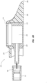
- the cover 150 can further include one or more protrusions 154, detents 156, or combinations thereof that are configured to engage a distal end of a placement tool, for example insertion tool 700 shown in FIG. 7 .
- the cover 150 is configured to substantially surround both the stem 130 and a portion of the catheter 50 that engages the stem 130. A distal portion of the placement tool 700 can then engage an outer surface of the cover 150 to manipulate both the port 110 and the catheter 50 attached thereto.
- FIGS. 2A-2H show various features of an embodiment of a port 210.
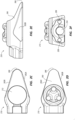
- the port 210 includes a port housing 212, a port body 214 including an extended tunneling portion 260 and a tunneling edge 266 that can be sharpened to facilitate implantation, and a needle penetrable septum 216, including palpation features 226.
- the housing 212 defines a reservoir 222 that is bounded by the needle-penetrable septum 216, and includes a stem aperture 234.
- the stem aperture 234 is configured for receiving a port stem 230.
- the port stem 230 is formed as a separate structure from the housing 212 and is configured to engage the stem aperture 234 to provide fluid communication between the reservoir 222 and a catheter 50.
- the port body 214 includes a stem cover 250, extending from a stem side of the port body 214.
- the stem cover 250 can define a cylindrical shaped recess with a substantially circular cross-section.
- the stem cover 250 further includes an opening 252 on a lower side.
- the stem cover 250 can further include one or more protrusions 254, detents 256, sockets 258, or combinations thereof that are configured to engage a distal end of a placement tool, for example placement tool 700.
- the distal end of the placement tool 700 engages an inner surface of the stem cover 250, an end surface of the stem cover 250, the stem aperture 234, or combinations thereof to secure the port 210 to a distal end of the placement tool 700.
- the placement tool can then be used to manipulate the port 210 into position within the body of the patient. Once the port 210 is in position, the tool disengages the port 210 and the clinician can optionally use the placement tool to attach the stem 230 and catheter 50.
- the stem 230 can be urged distally to engage the stem aperture 234.
- the catheter 50 can then engage the stem 230 to provide fluid communication between the reservoir 222 and the vasculature of the patient.
- the stem 230 and catheter 50 can be attached simultaneously.
- FIGS. 2C-F show various views of the port 210.
- a tunneling portion 260 of the body 214 extends away from the stem cover 250 to define an extended sigmoid slope shape, when viewed from a side profile.
- the tunneling portion 260 facilitates dissection of tissue by the port 210 to form a tissue pocket, as the port is urged subcutaneously.
- port body 214 further includes one or more skives 262A, 262B extending along a side portion of the body 214 and angled to define a tapered, substantially triangular-shaped footprint to the port 210 when viewed from a plan view.
- the skives 262 further define a streamlined overall profile to the port 210 and, together with the tunneling edge 266 and profile of the tunneling portion 260, further allows the port 210 to be urged through the tissue to define a tissue pocket while minimizing potential scarring.
- FIG. 2G shows an embodiment of a port 208.
- port 208 includes a port housing 212, a port body 214 including an extended tunneling portion 260 and a sharpened tunneling edge 266 to facilitate implantation, and a needle penetrable septum 216, including palpation features 226.
- the port 208 further includes a stem cover 250 extending from a stem side of the port body 214.
- the stem cover 250 can define a cylindrical shaped recess with a substantially circular cross-section.
- the stem cover 250 further includes an opening 252 on a lower side as well as one or more protrusions 254, detents 256, sockets 258, or combinations thereof that are configured to engage a distal end of a placement tool, for example placement tool 700.
- socket 258 includes an opening on an inner surface, communicating with the cylindrical recess defined by the stem cover 250.
- the stem portion 230 can be formed as a separate structure from the port housing 212 and engages a stem aperture 234.
- an ingrowth guard 270 can be disposed within the recess defined by the stem cover 250, sockets 258, or combinations thereof.
- the ingrowth guard 270 further includes a recess 272 for receiving a stem 230 and a portion of a catheter and/or catheter lock 50 connected to the stem 230. As shown in FIGS. 2H , the ingrowth guard substantially fills the void created between an inner surface of the stem cover and an outer surface of the catheter 50 when coupled to the port.
- Implanted subcutaneous access ports are expected to have a certain amount of ingrowth around, for example, the port, stem, etc.
- the amount of tissue ingrowth can increase with geometry such as holes, and indentations that provide recesses for the tissue to grow into.
- the ingrowth guard prevents any tissue from growing into the recesses between the catheter and/or catheter lock 50 and the port body stem cover 250. Accordingly, when the port is removed, the catheter 50, ingrowth guard 270, and optionally the stem 230 can be removed to provide a clean surface with which the placement tool 700 can engage. Without the ingrowth guard 270 in place, tissue growth can obstruct the protrusions 254, detents 256, sockets 258, or combinations thereof and prevent the placement tool 700 from engaging the port 208, 210.
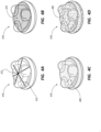
- FIGS. 3A-G show embodiments of an implantable access port 310.
- the port 310 includes a port housing 312, a port body 314 including a tunneling edge 366 to facilitate implantation, and a needle penetrable septum 316, including palpation features 326.
- the housing 312 defines a reservoir 322 bounded by the needle-penetrable septum 316 and includes a stem 330.
- the stem 330 configured for engaging a catheter 50 and providing fluid communication between the reservoir 322 and the catheter 50.
- embodiments of the port 310 define a low-profile so that a minimum horizontal length or width of the port 310 is greater than the maximum vertical height of the port 310.
- Typical power injection ports define a substantially higher profile in order to provide a sufficiently strong septum and tall enough reservoir.
- embodiments described herein define a substantially lower profile for a similar overall footprint.
- the footprint of the port 310 can vary in shape including circular e.g. port 310A, crescent shape or a reniform 'kidney bean' shape, e.g. 310B, 310C. It will be appreciated that other shapes of port footprint are also contemplated including triangular, trapezoid, hexagon, polygon, and the like.
- Embodiments of port 310 also define a substantially flat underside and a continuous, smooth, rounded upper side. These profile shapes allow the port 310 to define a relatively smooth, unobtrusive shape and reduces tissue stress points on an exterior of embodiments of the port 310. Further, the profile of the body 314 minimizes tension on the subcutaneous tissue pocket and sutures that close the post-insertion incision, this in turn minimizes the formation of scar tissue.
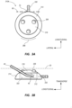
- FIG. 3A shows an incision line 60 through which port 310A is inserted subcutaneously.
- the circular footprint and rounded upper surface minimizes the area of stress points 70 on the incision 60, thereby minimizing the formation of scar tissue.
- the circular footprint allows the port 310A to be eased through an incision that is less than the maximum width of the port 310A itself, thereby allowing for a smaller incision site 60.
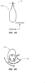
- FIG. 3C shows port 310B with a crescent shape, or reniform "kidney bean" shape footprint including a convex tunneling portion 360, first and second lobes 336, 338, and a concave stem-side portion 362.
- a stem 330 extending from the stem-side portion 362, along a longitudinal axis.
- a tunneling edge 366 can be sharpened and extends from a first side, proximate a first lobe 336, through to a second side, proximate a second lobe 338.
- the incision 60 required to insert the port 310B subcutaneously can be shorter than the lateral width of the port 310B and the same length as a longitudinal length (y) of the port 310 that extends along a longitudinal axis between the stem-side portion 362 at the base of the stem 330, and the tunneling portion 360.
- positioning the port 310B subcutaneously includes inserting the port 310B sideways with the first lobe 336 passing through the incision 60 first.
- the port 310B is then inserted by rotating through substantially 90° about a transverse axis until a second lobe 338 passes through the incision 60.
- the sharpened tunneling edge 366 facilitates separation of the tissue thereby forming a tissue pocket.
- the stress points 70, adjacent the first and second lobes 364, 368 are positioned away from a mid-point of the incision 60 and closer to the end points of the incision 60, diverting any stress on the incision sutures away from the relatively weaker mid-point of the incision 60.
- the incision 60 is formed by a scalpel.
- the tunneling edge 366 can include a blade to nick the skin and form the incision 60. In an embodiment the blade is retractable.
- FIG. 3E shows port 310C with an extended crescent shape, or 'kidney bean' shape footprint including a convex tunneling portion 360, first and second lobes 336, 338, and a concave stem-side portion 362.
- the stem 330 extending along a longitudinal axis from the stem-side portion 362.
- a tunneling edge 366 can extend from a first side through to a second side.
- the incision 60 required to insert the port 310C subcutaneously can be shorter than the lateral width of the port 310C and the same length as a longitudinal length (y) of the port extending along a longitudinal axis from the stem-side portion 362, at the base of the stem 330, through to the tunneling portion 360.
- positioning the port 310C subcutaneously includes inserting the port 310C sideways with the first lobe 336 passing through the incision 60 first.
- the port 310C is then inserted by rotating through substantially 90° about a transverse axis until a second lobe 338 passes through the incision 60.
- the sharpened tunneling edge 366 facilitates separation of the tissue forming a tissue pocket.
- the stress points 70, adjacent the first and second lobes 364, 368 are positioned away from the incision 60, reducing any stress on the incision sutures and reducing the formation of scar tissue.
- FIG. 3G shows an embodiment of port 310D including an elongate balloon shaped footprint. Similar to port 310A, port 310D includes rounded edges to facilitate passing through an incision 60, the incision 60 extending laterally the same or slightly less than the lateral width of the port. 310D.
- the shape of port 310D provides a larger target area with which to access the port and yet does not require any larger of an incision 60. Further the larger target area allows an access needle to be inserted at an acute angle to the skin surface, as discussed in more detail herein.
- the septum 316 defines a convex profile when viewed from a side view.
- the convex septum 316 allows an access needle 40, such as a Huber-type, non-coring needle, to pass through the septum 316 at an acute angle relative to a skin surface 20 of the patient and access the reservoir 322 therebelow.
- the access needle can pass through the septum at an angle of 90° or less relative to a horizontal plane of the port 310.
- the angled entry position allows the entire opening of the needle lumen to remain within the reservoir 322 even if the transverse depth of the reservoir 322 is shorter than a maximum width (x) of the needle bevel 42.
- this allows the port 310 to define a lower profile than typical ports while still enabling the entire needle bevel 42 to fit within the reservoir 322.
- a septum 416 can include reinforcements such as wires, particles, or combinations thereof. It will be appreciated that any of septa 116, 216, 316 can also include reinforcements described herein.
- the reinforcements can include one or more wires 470 extending through the septum 416.
- the wires can be formed of metal such as titanium or stainless steel, polymers such as nylon, ceramics, or any suitable material.
- the wires 470 can extend from a first side to a second side, and at least one of the wires 470 can pass through a center-point 472 of the septum 416. In an embodiment, as shown in FIG.
- the wires 470 form a mesh structure extending through the septum 416.
- the openings between the individual strands of wires 470 are sufficient to allow an access needle 40 to pass therebetween.
- the septum 416 can be formed by overmolding needle penetrable silicone rubber over the wires 470.
- the septum 416 includes particles 480 to create a reinforced composite material.
- the particles 480 can include metal, ceramics, polymers, or combinations thereof.
- the particles 480 can range in size from 10 nm to 1.0 mm in diameter, and are disposed within a matrix of silicone rubber to form the septum 416.
- the septum 416 includes filaments 482 to create a reinforced composite material.
- the septum 416 can include a matrix of silicone rubber and woven or non-woven filaments 480 disposed therein.
- the filaments can be between 1 mm and 15 mm in length and formed of metal, ceramics, polymers, or combinations thereof.
- the reinforcements of the septum 416 allow the septum 416 to define a thinner transverse height while maintaining the ability to withstand typical power injection pressures. Further, the reinforcements can also define a septum with a convex profile, as described herein. Accordingly, a port including the reinforced septum 416 can define a lower profile, reducing stress placed on the surrounding tissue.
- FIGS. 5A-D depicts various details of an implantable access port placement tool (“placement tool” or “tool”), generally designated at 500, according to an embodiment.
- the tool 500 includes an elongate body 514 extending between a distal end 560 and proximal end 562.
- a proximal portion of the body defines a handle 516 for grasping of the tool.
- the handle can further include a grip surface 518 to assist the grasping of the tool 500.
- the tool 500 further includes a port holder 510 disposed at a distal end 560 of the tool 500.
- the port holder 510 is configured to releasably hold an access port 30 prior to its placement in a subcutaneous tissue pocket defined in the placement tool 500.
- port 30 can include any of the port embodiments 110, 210, 310 disclosed herein as well as other generic access ports.
- the port holder includes a base 540 defining a flat underside and an elliptical perimeter 528 extending from a first side, to a distal end 560, to a second side.
- the footprint of the elliptical perimeter 528 substantially matches the footprint of a port 30.
- Extending from the elliptical perimeter 528 is a panel 524 that defines a cavity 522.
- the cavity 522 is configured to receive a portion of the access port 30.
- the panel 524 is angled in a proximal direction and curved to match the elliptical perimeter 528.
- a side profile of the panel 524 extends proximally from the elliptical perimeter 528 to provide a sloping tunneling portion that facilitates dissection of tissue as the placement tool is urged subcutaneously.
- the port holder 510 is sized to match the approximate size of the access port 30, enabling the clinician using the placement tool 500 to insert the port holder into a subcutaneous pocket and determine whether the pocket is sufficiently sized to receive the access port 30 prior to insertion. This simplifies the placement of the port 30 for the clinician. It will be appreciated that size, shape and configuration of the port holder 510, the base 540, the curved panel 524, or combinations thereof, can vary in order to receive different sizes, shapes and configurations of port 30. In an embodiment, a portion of the elliptical perimeter 528 can be sharpened to provide a sharpened tunneling edge 566.
- the tunneling edge 566 can be used to separate the tissue of the patient and define the subcutaneous tissue pocket into which the access port 30 will be placed.
- a portion of the elliptical perimeter 528 includes a blade for nicking the skin and forming an incision.
- the blade is formed of separate material from the tool 500, or port holder 510 and is selectively retractable.
- the tool 500 provides a single instrument within which to create an incision, separate the subcutaneous tissues to create a tissue pocket, size the tissue pocket to match the size of the port, and place the port within the tissue pocket, or combinations thereof.
- the tool 500 provides an instrument that performs the incision, separation, sizing and placing of the port 30, or combinations thereof, in a single action.
- the port holder includes a first and second curved panel arms 524A, 524B.
- Each of panel arms 524A, 524B engage along a longitudinal axis to define a profile substantially the same as panel 524.
- Each of first and second curved panel arms 524A, 524B are hingedly connected to the port holder 510 at a side portion and rotate thereabout along a horizontal plane.
- the first and second curved panel arms 524A, 524B can also be operably connected to an actuator 530 located on the handle 516.
- a clinician can selectively release the port 30 from the port holder 510 by actuating the actuator 530 which causes the first and second curved panel arms 524A, 524B to open and release the port 30.
- the tool 500, along with port holder 510 can then be removed proximally while leaving the port 30 in place.
- a port is provided such as is discussed in embodiments herein.
- the port can be coupled to a distal end of a placement tool, for example tool 500.
- the placement tool 500 includes a port holder 510 that includes a recess 522.
- the port engages the recess of the port holder and is secured thereto.
- the placement tool further includes a sharpened tunneling edge 566 and a sloped profile to facilitate formation of a tissue pocket as the tool is urged subcutaneously.
- an incision is formed either by using a scalpel, or by using the tunneling edge 566 of the placement tool 500 that includes a blade, the tool is then urged subcutaneously.
- the sharpened tunneling edge and sloped profile of the panel simultaneously dissects the tissue to form a tissue pocket and sizes the pocket to fit the port.
- the placement tool is then withdrawn and the port is then placed within the tissue pocket.
- the port is coupled with the port holder 510 prior to subcutaneous placement of the tool 500. With the port placed subcutaneously, the user actuates an actuator mechanism 530 which causes the panel arms 524A, 524B to rotate outwards and release the port from the distal end of the placement tool 500. The placement tool 500 can then be withdrawn.
- the placement tool 502 includes an elongate body 514 extending between a distal end 560 and a proximal end 562.
- a proximal portion of the body 514 defines a handle 516 for grasping of the tool.
- the handle can further include a grip surface 518 to assist the grasping of the tool 502.
- the tool 502 further includes a flattened base portion 540 disposed at a distal end 560.
- the base portion 540 defines an elliptically-shaped tunneling edge 566 that can be sharpened to facilitate tissue dissection and formation of a tissue pocket.
- the tunneling edge 566 can include a blade for nicking the skin and forming an incision. As shown in FIG.
- a plan view of the base portion 540 shows the base 540 defining a footprint that substantially matches the footprint of a port 30. It will be appreciated that the shape of the base portion 540 can vary to match the shape of the port footprint it is configured to insert.
- the placement tool 502 is grasped by the clinician and urged subcutaneously.
- the tool 502 includes a blade to nick the skin and form an incision, through which the tool 502 is then urged.
- the incision is formed by a scalpel.
- the tool 502 is then urged subcutaneously to dissect the tissue until the entire base portion 540 is disposed within the patient. Since the shape of the base portion 540 is the same, or slightly larger than a footprint of the port 30 to be inserted, the tool 502 defines a tissue pocket of a suitable size and depth. The placement tool 502 can be withdrawn and the port 30 can be disposed within the tissue pocket.
- port placement can be performed with or without a catheter 50 coupled to the port 30.
- the placement tools 500, 502 are formed of metal, polymer, plastic, or any suitable rigid material, or combinations thereof.
- the tool body 514 can be formed of a polymer and include a metallic tunneling edge 566. These and similar combinations are contemplated to fall within the scope of the present invention.
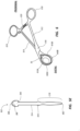
- the placement tool 600 includes a first arm 612 extending from a proximal end to a distal end, and a second arm 614 also extending from a proximal end to a distal end.
- the first and second arms 612, 614 are hingedly connected at a mid-portion 616.
- a proximal end of each of the first and second arms 612, 614 include a finger loop 618, or similar structure to allow the clinician to grip each of the first and second arms 612, 614 with a finger or thumb.
- the tool 600 further includes a latch 620 disposed between the first and second arms 612, 614 and designed to lock the first and second arms 612, 614 in one or more closed positions. As shown, the latch 620 is disposed towards a proximal end, although other configurations are contemplated.
- a distal end of the first and second arms 612, 614 each include a port holder 610, e.g. first and second port holder 610A, 610B.
- the port holder 610 is configured to receive a side portion of a port 30.
- the port holder includes a curved loop shaped to receive a lobe of the port body although it will be appreciated that the shape of the port holder 610 can vary to fit different shaped ports.
- a distal end of the first arm 612, the second arm 614, or combinations thereof also include a blade 640.
- the blade 640 extends distally from a distal end of the port holder 610.
- the blade 640 can define a crescent shape that extends around and in front of a port 30 disposed within the port holder.
- the blade, 640 can include a sharpened distal edge for forming an incision and dissecting tissue.
- both the first and second arms 612, 614 each include a blade 640, e.g. first and second blades 640A, 640B, which engage at a lateral mid-point when the placement tool 600 is in one or more closed positions.
- each of the blades 640A, 640B can slide over each other in a scissor-like action as the finger loops are moved toward and apart from each other by the clinician.
- the placement tool 600 can secure a port 30 between each of the port holders 610A, 610B.
- a user can close the port holder 610 about the port 30 by moving the finger loops 618 toward each other until the latch 620 engages and locks the placement tool 600 in a closed position.
- the clinician can then urge the placement tool subcutaneously, by using the blade 640 to form an incision.
- the clinician continues to urge the placement tool 600 subcutaneously to dissect the tissue and form a tissue pocket.
- the clinician can unlock the latch 620 and move the finger loops 618 apart to release the port 30.
- the placement tool 600 can then be withdrawn. It will be appreciated that port placement can be performed with or without a catheter 50 coupled to the port 30.
- the placement tool 600 is formed of metal, polymer, plastic, or any suitable rigid material, or combinations thereof.
- the first and second arms 612, 614 can be formed of a polymer and include a metallic sharpened blade 640 disposed therein. These and similar combinations are contemplated to fall within the scope of the present invention.
- FIG. 7 shows an embodiment of a placement tool 700.
- the placement tool 700 includes an elongate body 714 extending between a distal end 760 and proximal end 762. A proximal portion of the body defines a handle 716 for grasping the tool. A distal portion of the tool 700 further includes a port holder 710. The port holder 710 is configured to releasably secure an access port 30, for example ports 110, 210, prior to placement in a subcutaneous pocket defined in the body of a patient.
- the port holder 710 includes mechanisms for securing the port holder 710 to the port, for example to the stem cover 150.
- the mechanisms include various latches, protrusions, abutments, detents, connectors, and the like, for releasably securing the port holder 710 to the port stem cover 150.
- the handle 716 includes an actuator 730 that is operably connected to mechanisms within the port holder 710. In use, a clinician can actuate the actuator 730 to selectively release the stem cover 150 from a distal connecting portion 760 of the port holder 710.
- the placement tool 700 further includes a safety clip 770 to prevent premature release of the port 30 from the tool 700.
- a port is provided such as is discussed in embodiments herein.
- the port can be coupled to a distal end of a placement tool, e.g. tool 700 in an embodiment, the placement tool engages a stem cover.
- the placement tool engages an outer surface of the stem cover and the port is coupled to the catheter prior to insertion.
- the placement tool engages an inner surface of the stem cover, an end surface of the stem cover, a stem aperture 234, or combinations thereof.
- the catheter 50 and stem portion 230 are engaged with the port after subcutaneous insertion.
- the port further includes a tunneling edge and a sloped profile to facilitate formation of a tissue pocket by the port.
- an incision is formed by either using a scalpel, or by using a sharpened edge of the port.
- the port is then urged subcutaneously using the placement tool.
- the tunneling edge and sloped profile of the tunneling portion of the port simultaneously dissects the tissue to form a tissue pocket as well as sizes the pocket to fit the port.
- the user actuates an actuator mechanism which releases the port from a distal end of the placement tool.
Landscapes
- Health & Medical Sciences (AREA)
- Heart & Thoracic Surgery (AREA)
- Pulmonology (AREA)
- Engineering & Computer Science (AREA)
- Anesthesiology (AREA)
- Biomedical Technology (AREA)
- Hematology (AREA)
- Life Sciences & Earth Sciences (AREA)
- Animal Behavior & Ethology (AREA)
- General Health & Medical Sciences (AREA)
- Public Health (AREA)
- Veterinary Medicine (AREA)
- Media Introduction/Drainage Providing Device (AREA)
- Infusion, Injection, And Reservoir Apparatuses (AREA)
Claims (14)
- Subkutanes Zugangsportsystem, umfassend:ein Platzierungswerkzeug (500, 600, 700), einschließlich eines proximalen Handgriffs (516, 618, 716) und eines distalen Porthalters (510, 610A, 610B, 710); undeinen implantierbaren Zugangsport (110, 210), der an dem Porthalter (510, 610A, 610B, 710) lösbar befestigt ist, wobei der implantierbare Zugangsport (110, 210) umfasst:ein Gehäuse (112, 212), einschließlich einer Basis (120) und eines Reservoirs (122, 222);ein nadeldurchlässiges Septum (116, 216), das das Reservoir (122, 222) abdeckt; undeinen Körper (114, 214), der mit dem Gehäuse (112, 212) über das nadeldurchlässige Septum (116, 216) gekoppelt ist, wobei der Körper (114, 214) umfasst:eine Schaftabdeckung (150, 250), die zum Eingreifen in den distalen Porthalter (510, 610A, 610B, 710) konfiguriert ist; undeine Tunnelkante (166, 266), die zu der Schaftabdeckung (150, 250) entgegengesetzt ist,wobei die Tunnelkante (166, 266) geschärft ist, um eine Zerteilung des Gewebes beim subkutanen Vorschieben des implantierbaren Zugangsports (110, 210) zu erleichtern.
- Subkutanes Zugangsportsystem nach Anspruch 1, weiter umfassend einen Indexmarker, wobei der Indexmarker zwischen der Basis (120) und dem Körper (114, 214, 314) angeordnet ist, und wobei bevorzugt der Indexmarker röntgendicht ist und eines von einem alphanumerischen Symbol und einer Form einschließt, das/die eines von einem Merkmal und einer Ausrichtung des Ports (110, 210) anzeigt.
- Subkutanes Zugangsportsystem nach Anspruch 1 oder 2, wobei das Platzierungswerkzeug (500, 600, 700) in eine Außenfläche der Schaftabdeckung (150, 250) eingreift.
- Subkutanes Zugangsportsystem nach Anspruch 1 oder 2, wobei das Platzierungswerkzeug (500, 600, 700) in eine von einer Innenfläche der Schaftabdeckung (150, 250), einer Endfläche der Schaftabdeckung (150, 250) und einer Schaftöffnung (234) des Gehäuses (112, 212) eingreift, wobei die Schaftöffnung (234) auch zum Aufnehmen eines Schaftabschnitts (130, 230) konfiguriert ist, wobei der Schaftabschnitt (130, 230) eine Fluidverbindung zwischen dem Reservoir (122, 222) und einem daran angebrachten Katheter (50) bereitstellt.
- Subkutanes Zugangsportsystem nach einem der vorstehenden Ansprüche, wobei die Schaftabdeckung (150, 250) eines von einem Vorsprung, einer Klinke und einer Ausnehmung einschließt, der/die zum Eingreifen in dasPlatzierungswerkzeug (500, 600, 700) konfiguriert ist.
- Subkutanes Zugangsportsystem nach einem der vorstehenden Ansprüche, wobei der Körper (114, 214) weiter eine Ausfensterung (262A, 262B) an einer Seitenfläche davon einschließt, wobei die Ausfensterung (262A, 262B) einen verjüngten Fußabdruck des distalen Abschnitts des Körpers (114, 214) definiert.
- Subkutanes Zugangsportsystem nach einem der vorstehenden Ansprüche, wobei das Septum (116, 216) eine konvexe obere Fläche definiert, um einer Nadel (40) einen Zugang zu dem Reservoir (122, 222) in einem spitzen Winkel in Bezug auf eine Hautoberfläche des Patienten zu ermöglichen.
- Subkutanes Zugangsportsystem nach einem der vorstehenden Ansprüche, wobei eine vertikale Tiefe des Reservoirs (122, 222) geringer als eine Maximallänge einer Abschrägung einer Zugangsnadel (40) ist, die Zugang zu dem Port (110, 210) hat.
- Subkutanes Zugangsportsystem nach einem der vorstehenden Ansprüche, wobei eine Form des Fußabdrucks des Ports (110, 210) eine von einer Kreis-, einer Sichel-, einer Nieren-, einer länglichen Ballon- und einer Pfeilform einschließt.
- Subkutanes Zugangsportsystem nach einem der vorstehenden Ansprüche, wobei das Septum (116, 216) eine Verstärkung einschließt.
- Subkutanes Zugangsportsystem nach Anspruch 10, wobei die Verstärkung eine von einer Drahtverstärkung und einer Matrixverstärkung einschließt.
- Subkutanes Zugangsportsystem nach Anspruch 10 oder 11, wobei die Verstärkung ein Drahtnetz einschließt.
- Subkutanes Zugangsportsystem nach einem der Ansprüche 10-12, wobei die Verstärkung eine Mehrzahl von individuellen Drahtlitzen (470) einschließt und sich eine der individuellen Drahtlitzen (470) durch einen Mittelpunkt des Septums (116, 216) erstreckt.
- Subkutanes Zugangsportsystem nach Anspruch 10 oder 11, wobei die Verstärkung eine Matrix aus Silikonkautschuk mit einer von einer Mehrzahl von Partikeln und einer Mehrzahl von Fasern einschließt, die darin angeordnet sind, und wobei bevorzugt die Mehrzahl von Partikeln aus einem von einem Metall, einer Keramik und einem Polymer gebildet ist und die Partikel einen Durchmesser mit einer Größe im Bereich von 10 nm bis 1,0 mm aufweisen, oder wobei die Mehrzahl von Fasern aus einem von einem Metall, einer Keramik und einem Polymer gebildet ist und die Fasern einen Durchmesser mit einer Länge im Bereich von 1 mm und 15 mm aufweisen.
Applications Claiming Priority (4)
| Application Number | Priority Date | Filing Date | Title |
|---|---|---|---|
| US201862713968P | 2018-08-02 | 2018-08-02 | |
| US201862743434P | 2018-10-09 | 2018-10-09 | |
| US201862743419P | 2018-10-09 | 2018-10-09 | |
| PCT/US2019/044966 WO2020028847A1 (en) | 2018-08-02 | 2019-08-02 | Implantable port placement system including low-scarring exterior |
Publications (4)
| Publication Number | Publication Date |
|---|---|
| EP3820559A1 EP3820559A1 (de) | 2021-05-19 |
| EP3820559A4 EP3820559A4 (de) | 2022-08-03 |
| EP3820559B1 true EP3820559B1 (de) | 2025-06-18 |
| EP3820559C0 EP3820559C0 (de) | 2025-06-18 |
Family
ID=69230744
Family Applications (1)
| Application Number | Title | Priority Date | Filing Date |
|---|---|---|---|
| EP19844795.5A Active EP3820559B1 (de) | 2018-08-02 | 2019-08-02 | Platzierungssystem für implantierbaren port mit aussenteil mit niedriger vernarbung |
Country Status (5)
| Country | Link |
|---|---|
| US (1) | US12589230B2 (de) |
| EP (1) | EP3820559B1 (de) |
| JP (1) | JP2021531920A (de) |
| CN (1) | CN112601575B (de) |
| WO (1) | WO2020028847A1 (de) |
Families Citing this family (14)
| Publication number | Priority date | Publication date | Assignee | Title |
|---|---|---|---|---|
| WO2020028847A1 (en) | 2018-08-02 | 2020-02-06 | Bard Peripheral Vascular, Inc. | Implantable port placement system including low-scarring exterior |
| EP3934733A4 (de) | 2019-03-03 | 2022-11-16 | Portal Access, Inc. | Subkutan austauschbarer vaskulärer zugangsanschluss |
| US20220008706A1 (en) * | 2020-07-08 | 2022-01-13 | Portal Access, Inc. | Minimally invasive port implantation |
| AU2020478795B2 (en) | 2020-11-24 | 2025-09-25 | Bard Peripheral Vascular, Inc. | Access needle indication systems for locating and accessing subcutaneous medical devices |
| CA3204585A1 (en) * | 2020-12-09 | 2022-06-16 | Portal Access, Inc. | Squeezable subcutaneous port |
| WO2022149086A1 (en) * | 2021-01-07 | 2022-07-14 | Establishment Labs S.A. | Medical implant port assemblies and related methods |
| AU2021444487B2 (en) * | 2021-05-07 | 2025-12-18 | Bard Peripheral Vascular, Inc. | Low profile, injectable subcutaneous vascular access system and method |
| FR3124087B1 (fr) * | 2021-06-17 | 2023-06-23 | Vygon | Chambre implantable et nécessaire associé |
| WO2023282903A1 (en) | 2021-07-08 | 2023-01-12 | Bard Peripheral Vascular, Inc. | Prosthesis with integrated therapeutic delivery system |
| JP7789902B2 (ja) * | 2021-09-10 | 2025-12-22 | バード・ペリフェラル・バスキュラー・インコーポレーテッド | 抗内方成長カテーテルロックシステム及びカテーテルの結合方法 |
| EP4463214A1 (de) * | 2022-01-21 | 2024-11-20 | Bard Peripheral Vascular, Inc. | Portidentifikationseinsatz und verfahren |
| EP4463213A1 (de) * | 2022-01-21 | 2024-11-20 | Bard Peripheral Vascular, Inc. | Portidentifikationseinsatz und anordnungsausrichtungsfunktion |
| EP4321204A1 (de) * | 2022-08-10 | 2024-02-14 | Lucas Krauel Giménez-Salinas | Subkutane gefässzugangsvorrichtungen und -verfahren |
| WO2025184547A1 (en) * | 2024-02-29 | 2025-09-04 | Nevro Corp. | Apparatus and method for forming a subcutaenous pocket |
Family Cites Families (72)
| Publication number | Priority date | Publication date | Assignee | Title |
|---|---|---|---|---|
| US341473A (en) | 1886-05-11 | Crucible-tongs | ||
| US4751926A (en) * | 1986-09-12 | 1988-06-21 | Dow Corning Wright Corporation | Instrument for subcutaneous insertion of an injection reservoir |
| US4781680A (en) * | 1987-03-02 | 1988-11-01 | Vir Engineering | Resealable injection site |
| US4857053A (en) * | 1988-08-29 | 1989-08-15 | Dalton Michael J | Matrix septum |
| US5147483A (en) | 1989-04-26 | 1992-09-15 | Therex Corporation | Implantable infusion device and method of manufacture thereof |
| US5137529A (en) * | 1990-02-20 | 1992-08-11 | Pudenz-Schulte Medical Research Corporation | Injection port |
| US5562618A (en) | 1994-01-21 | 1996-10-08 | Sims Deltec, Inc. | Portal assembly and catheter connector |
| US5989216A (en) | 1995-06-29 | 1999-11-23 | Sims Deltec, Inc. | Access portal and method |
| US5951512A (en) | 1996-05-28 | 1999-09-14 | Horizon Medical Products, Inc. | Infusion port with modified drug reservoir |
| US5919160A (en) * | 1996-10-10 | 1999-07-06 | Sanfilippo, Ii; Dominic Joseph | Vascular access device and method of installing same |
| US5792104A (en) | 1996-12-10 | 1998-08-11 | Medtronic, Inc. | Dual-reservoir vascular access port |
| US5833654A (en) | 1997-01-17 | 1998-11-10 | C. R. Bard, Inc. | Longitudinally aligned dual reservoir access port |
| US6190352B1 (en) | 1997-10-01 | 2001-02-20 | Boston Scientific Corporation | Guidewire compatible port and method for inserting same |
| US6213973B1 (en) * | 1998-01-12 | 2001-04-10 | C. R. Bard, Inc. | Vascular access port with elongated septum |
| US8177762B2 (en) | 1998-12-07 | 2012-05-15 | C. R. Bard, Inc. | Septum including at least one identifiable feature, access ports including same, and related methods |
| AU2002237947B2 (en) * | 2001-01-24 | 2008-02-21 | Becton, Dickinson And Company | Lubricious coating for medical device |
| US8574204B2 (en) | 2002-10-21 | 2013-11-05 | Angiodynamics, Inc. | Implantable medical device for improved placement and adherence in the body |
| FR2846245B1 (fr) * | 2002-10-25 | 2005-03-25 | Braun Medical | Dispositif medical implantable par voie sous-cutanee |
| US20040199129A1 (en) | 2003-04-07 | 2004-10-07 | Scimed Life Systems, Inc. | Vascular access port |
| DK1662971T3 (da) | 2003-09-15 | 2011-08-29 | Allergan Inc | Fastgørelsessystem til en implanterbar indretning |
| US20050131383A1 (en) * | 2003-12-16 | 2005-06-16 | How-Lun Chen | Method for implanting flexible injection port |
| CN1897880A (zh) | 2004-01-23 | 2007-01-17 | 伊娜梅德医药产品公司 | 可植入装置的紧固系统和其使用方法 |
| US7699821B2 (en) | 2004-03-12 | 2010-04-20 | Covance Laboratories Gmbh | Multi-functional port |
| US7909804B2 (en) | 2005-02-07 | 2011-03-22 | C. R. Bard, Inc. | Vascular access port with integral attachment mechanism |
| US20060217673A1 (en) * | 2005-03-22 | 2006-09-28 | Schulze Dale R | Subcutaneous injection port with stabilizing elements |
| US7918844B2 (en) * | 2005-06-24 | 2011-04-05 | Ethicon Endo-Surgery, Inc. | Applier for implantable medical device |
| GB2433032A (en) * | 2005-12-08 | 2007-06-13 | Owen Mumford Ltd | Syringe with dose adjustment means |
| US7708722B2 (en) | 2006-01-10 | 2010-05-04 | Stealth Therapeutics, Inc. | Stabilized implantable vascular access port |
| US7972314B2 (en) | 2006-03-29 | 2011-07-05 | Medical Components, Inc. | Venous access port base |
| WO2008063226A2 (en) | 2006-05-22 | 2008-05-29 | Medical Components, Inc. | Septum for venous access port assembly |
| WO2008048361A1 (en) | 2006-10-18 | 2008-04-24 | Medical Components, Inc. | Venous access port assembly with radiopaque indicia |
| AT504511B1 (de) | 2006-12-20 | 2008-06-15 | Ami Gmbh | Portkatheter |
| PT3269417T (pt) | 2007-06-20 | 2025-11-05 | Medical Components Inc | Dispositivo de acesso implantável com indicações moldadas e/ou radiopacas |
| CN101678199B (zh) | 2007-06-22 | 2013-10-30 | 医疗器械公司 | 薄型静脉接入端口组件 |
| MX2010000703A (es) | 2007-07-19 | 2010-07-29 | Medical Components Inc | Ensamble de puerto de acceso venoso con indicaciones que se distinguen para rayos x. |
| WO2009012395A1 (en) | 2007-07-19 | 2009-01-22 | Innovative Medical Devices, Llc | Venous access port assembly with x-ray discernable indicia |
| AU2008299945A1 (en) | 2007-09-07 | 2009-03-19 | Angiodynamics, Inc. | Implantable access port |
| AU2009219375B2 (en) * | 2008-02-29 | 2014-10-02 | Medical Components, Inc. | Venous access port assembly with push surfaces |
| AT10474U1 (de) * | 2008-04-15 | 2009-04-15 | A M I Agency For Medical Innov | Portkatheter zum einbringen einer flüssigkeit in ein hohlorgan eines menschlichen oder tierischen körpers |
| RU2464048C2 (ru) * | 2008-04-17 | 2012-10-20 | Аллерган, Инк. | Имплантируемый порт доступа и система его крепления |
| US8075536B2 (en) * | 2008-09-09 | 2011-12-13 | Navilyst Medical, Inc. | Power injectable port identification |
| EP2346417A4 (de) * | 2008-10-20 | 2017-04-26 | Spine View, Inc. | Retraktorkanülensystem für wirbelsäulenzugang und -visualisierung sowie entsprechende verfahren |
| US8932271B2 (en) | 2008-11-13 | 2015-01-13 | C. R. Bard, Inc. | Implantable medical devices including septum-based indicators |
| US10022094B2 (en) | 2009-02-04 | 2018-07-17 | Pfm Medical, Inc. | X-ray discernable marker for power injectable vascular access port |
| ES2635217T3 (es) * | 2009-04-28 | 2017-10-02 | Ostomycure As | Procedimiento de fabricación para implante percutáneo |
| US20110034886A1 (en) * | 2009-08-06 | 2011-02-10 | Angiodynamics, Inc. | Implantable medical device tool and method of use |
| US8506532B2 (en) * | 2009-08-26 | 2013-08-13 | Allergan, Inc. | System including access port and applicator tool |
| US8092435B2 (en) | 2009-10-16 | 2012-01-10 | Smiths Medical Asd, Inc. | Portal with septum embedded indicia |
| CN102612343B (zh) * | 2009-11-17 | 2015-11-25 | C·R·巴德股份有限公司 | 包括锚定装置和标识部分的包覆模制的进入端口 |
| US8657795B2 (en) * | 2009-12-30 | 2014-02-25 | Cook Medical Technologies Llc | Vascular port |
| WO2011133950A1 (en) | 2010-04-23 | 2011-10-27 | Medical Components, Inc. | Implantable dual reservoir access port |
| US8992415B2 (en) | 2010-04-30 | 2015-03-31 | Apollo Endosurgery, Inc. | Implantable device to protect tubing from puncture |
| EP3275657A1 (de) | 2010-05-05 | 2018-01-31 | Medical Components, Inc. | Verfahren und vorrichtung zum drucken röntgendichter markierungen |
| US9011388B2 (en) | 2010-06-04 | 2015-04-21 | Smiths Medical Asd, Inc. | Passive safety portal device |
| US20120041258A1 (en) * | 2010-08-16 | 2012-02-16 | Allergan, Inc. | Implantable access port system |
| US8409224B2 (en) * | 2010-10-04 | 2013-04-02 | Edgar L Shriver | Suturing graft tubes to lumen walls percutaneously |
| AU2011326519A1 (en) * | 2010-11-09 | 2013-05-30 | Hans-Dietrich Polaschegg | Hemodialysis access system |
| US8920390B2 (en) | 2011-03-19 | 2014-12-30 | Michael J. Dalton | Vascular access port with tubular shaped septum |
| WO2013094644A1 (ja) * | 2011-12-21 | 2013-06-27 | テルモ・クリニカルサプライ株式会社 | 皮下埋め込み型薬液注入具 |
| GB201202091D0 (en) * | 2012-02-07 | 2012-03-21 | Renishaw Ireland Ltd | Drug delivery apparatus |
| US9707339B2 (en) | 2012-03-28 | 2017-07-18 | Angiodynamics, Inc. | High flow rate dual reservoir port system |
| ES2745264T3 (es) * | 2012-08-21 | 2020-02-28 | Bard Inc C R | Orificio de acceso implantable que incluye una pieza de inserción intercalada |
| TW201440745A (zh) | 2013-03-14 | 2014-11-01 | Smiths Medical Asd Inc | 門靜脈及其隔膜 |
| EP3427787B1 (de) | 2013-10-08 | 2019-08-21 | Smiths Medical ASD, Inc. | Markierungszeichentragende septen, verfahren zur herstellung der septen und portal dafür |
| US10258502B2 (en) * | 2014-09-18 | 2019-04-16 | Orbit Biomedical Limited | Therapeutic agent delivery device |
| AU2015364276B2 (en) | 2014-12-18 | 2020-04-30 | Versago Vascular Access, Inc. | Devices, systems and methods for removal and replacement of a catheter for an implanted access port |
| US20180214680A1 (en) | 2017-02-01 | 2018-08-02 | Pfm Medical, Inc. | Identification system for injectable access ports |
| US20180214679A1 (en) | 2017-02-01 | 2018-08-02 | Pfm Medical, Inc. | Identification system for injectable access ports |
| EP3381501B1 (de) | 2017-03-30 | 2024-05-29 | PFM Medical AG | Implantierbare zugangsvorrichtung für den zugriff auf das gefässsystem eines menschlichen oder tierischen körpers |
| EP3560548A1 (de) | 2018-04-29 | 2019-10-30 | PFM Medical AG | Implantierbare zugangsvorrichtung zum zugriff auf das gefässsystem eines menschlichen oder tierischen körpers, insbesondere ein subkutan implantierbarer zugangsanschluss |
| WO2020028847A1 (en) | 2018-08-02 | 2020-02-06 | Bard Peripheral Vascular, Inc. | Implantable port placement system including low-scarring exterior |
| US10940290B2 (en) | 2018-08-27 | 2021-03-09 | Alcyone Lifesciences, Inc. | Fluid delivery systems and methods |
-
2019
- 2019-08-02 WO PCT/US2019/044966 patent/WO2020028847A1/en not_active Ceased
- 2019-08-02 JP JP2021505663A patent/JP2021531920A/ja active Pending
- 2019-08-02 EP EP19844795.5A patent/EP3820559B1/de active Active
- 2019-08-02 CN CN201980051522.5A patent/CN112601575B/zh active Active
- 2019-08-02 US US17/264,256 patent/US12589230B2/en active Active
Also Published As
| Publication number | Publication date |
|---|---|
| US12589230B2 (en) | 2026-03-31 |
| JP2021531920A (ja) | 2021-11-25 |
| EP3820559A1 (de) | 2021-05-19 |
| CN112601575A (zh) | 2021-04-02 |
| EP3820559C0 (de) | 2025-06-18 |
| WO2020028847A1 (en) | 2020-02-06 |
| US20210290923A1 (en) | 2021-09-23 |
| CN112601575B (zh) | 2023-04-04 |
| EP3820559A4 (de) | 2022-08-03 |
Similar Documents
| Publication | Publication Date | Title |
|---|---|---|
| EP3820559B1 (de) | Platzierungssystem für implantierbaren port mit aussenteil mit niedriger vernarbung | |
| US20240297350A1 (en) | Insertion device and method for delivery of a mesh carrier | |
| AU2003250147B2 (en) | IVS obturator instrument and procedure | |
| US12097106B2 (en) | Insertion device for delivery of a mesh carrier | |
| EP3420988B1 (de) | Werkzeug zur subkutanen verabreichung | |
| US7179232B2 (en) | Controlled orifice sampling needle | |
| US20110034886A1 (en) | Implantable medical device tool and method of use | |
| JP2021531920A5 (de) | ||
| ES2616319T3 (es) | Sistema de tratamiento de la incontinencia masculina |
Legal Events
| Date | Code | Title | Description |
|---|---|---|---|
| STAA | Information on the status of an ep patent application or granted ep patent |
Free format text: STATUS: THE INTERNATIONAL PUBLICATION HAS BEEN MADE |
|
| PUAI | Public reference made under article 153(3) epc to a published international application that has entered the european phase |
Free format text: ORIGINAL CODE: 0009012 |
|
| STAA | Information on the status of an ep patent application or granted ep patent |
Free format text: STATUS: REQUEST FOR EXAMINATION WAS MADE |
|
| 17P | Request for examination filed |
Effective date: 20210211 |
|
| AK | Designated contracting states |
Kind code of ref document: A1 Designated state(s): AL AT BE BG CH CY CZ DE DK EE ES FI FR GB GR HR HU IE IS IT LI LT LU LV MC MK MT NL NO PL PT RO RS SE SI SK SM TR |
|
| DAV | Request for validation of the european patent (deleted) | ||
| DAX | Request for extension of the european patent (deleted) | ||
| A4 | Supplementary search report drawn up and despatched |
Effective date: 20220630 |
|
| RIC1 | Information provided on ipc code assigned before grant |
Ipc: A61B 17/3209 20060101ALI20220624BHEP Ipc: A61M 5/142 20060101ALI20220624BHEP Ipc: A61M 39/00 20060101ALI20220624BHEP Ipc: A61B 17/00 20060101ALI20220624BHEP Ipc: A61M 39/02 20060101AFI20220624BHEP |
|
| STAA | Information on the status of an ep patent application or granted ep patent |
Free format text: STATUS: EXAMINATION IS IN PROGRESS |
|
| 17Q | First examination report despatched |
Effective date: 20231010 |
|
| GRAP | Despatch of communication of intention to grant a patent |
Free format text: ORIGINAL CODE: EPIDOSNIGR1 |
|
| STAA | Information on the status of an ep patent application or granted ep patent |
Free format text: STATUS: GRANT OF PATENT IS INTENDED |
|
| INTG | Intention to grant announced |
Effective date: 20250305 |
|
| GRAS | Grant fee paid |
Free format text: ORIGINAL CODE: EPIDOSNIGR3 |
|
| GRAA | (expected) grant |
Free format text: ORIGINAL CODE: 0009210 |
|
| STAA | Information on the status of an ep patent application or granted ep patent |
Free format text: STATUS: THE PATENT HAS BEEN GRANTED |
|
| AK | Designated contracting states |
Kind code of ref document: B1 Designated state(s): AL AT BE BG CH CY CZ DE DK EE ES FI FR GB GR HR HU IE IS IT LI LT LU LV MC MK MT NL NO PL PT RO RS SE SI SK SM TR |
|
| REG | Reference to a national code |
Ref country code: GB Ref legal event code: FG4D |
|
| REG | Reference to a national code |
Ref country code: CH Ref legal event code: EP |
|
| REG | Reference to a national code |
Ref country code: DE Ref legal event code: R096 Ref document number: 602019071353 Country of ref document: DE |
|
| REG | Reference to a national code |
Ref country code: CH Ref legal event code: EP |
|
| REG | Reference to a national code |
Ref country code: IE Ref legal event code: FG4D |
|
| U01 | Request for unitary effect filed |
Effective date: 20250618 |
|
| U07 | Unitary effect registered |
Designated state(s): AT BE BG DE DK EE FI FR IT LT LU LV MT NL PT RO SE SI Effective date: 20250626 |
|
| PG25 | Lapsed in a contracting state [announced via postgrant information from national office to epo] |
Ref country code: GR Free format text: LAPSE BECAUSE OF FAILURE TO SUBMIT A TRANSLATION OF THE DESCRIPTION OR TO PAY THE FEE WITHIN THE PRESCRIBED TIME-LIMIT Effective date: 20250919 Ref country code: NO Free format text: LAPSE BECAUSE OF FAILURE TO SUBMIT A TRANSLATION OF THE DESCRIPTION OR TO PAY THE FEE WITHIN THE PRESCRIBED TIME-LIMIT Effective date: 20250918 |
|
| PG25 | Lapsed in a contracting state [announced via postgrant information from national office to epo] |
Ref country code: HR Free format text: LAPSE BECAUSE OF FAILURE TO SUBMIT A TRANSLATION OF THE DESCRIPTION OR TO PAY THE FEE WITHIN THE PRESCRIBED TIME-LIMIT Effective date: 20250618 |
|
| PG25 | Lapsed in a contracting state [announced via postgrant information from national office to epo] |
Ref country code: RS Free format text: LAPSE BECAUSE OF FAILURE TO SUBMIT A TRANSLATION OF THE DESCRIPTION OR TO PAY THE FEE WITHIN THE PRESCRIBED TIME-LIMIT Effective date: 20250918 |
|
| PG25 | Lapsed in a contracting state [announced via postgrant information from national office to epo] |
Ref country code: IS Free format text: LAPSE BECAUSE OF FAILURE TO SUBMIT A TRANSLATION OF THE DESCRIPTION OR TO PAY THE FEE WITHIN THE PRESCRIBED TIME-LIMIT Effective date: 20251018 |
|
| PG25 | Lapsed in a contracting state [announced via postgrant information from national office to epo] |
Ref country code: SM Free format text: LAPSE BECAUSE OF FAILURE TO SUBMIT A TRANSLATION OF THE DESCRIPTION OR TO PAY THE FEE WITHIN THE PRESCRIBED TIME-LIMIT Effective date: 20250618 |
|
| PG25 | Lapsed in a contracting state [announced via postgrant information from national office to epo] |
Ref country code: CZ Free format text: LAPSE BECAUSE OF FAILURE TO SUBMIT A TRANSLATION OF THE DESCRIPTION OR TO PAY THE FEE WITHIN THE PRESCRIBED TIME-LIMIT Effective date: 20250618 |
|
| PG25 | Lapsed in a contracting state [announced via postgrant information from national office to epo] |
Ref country code: PL Free format text: LAPSE BECAUSE OF FAILURE TO SUBMIT A TRANSLATION OF THE DESCRIPTION OR TO PAY THE FEE WITHIN THE PRESCRIBED TIME-LIMIT Effective date: 20250618 |
|
| PG25 | Lapsed in a contracting state [announced via postgrant information from national office to epo] |
Ref country code: SK Free format text: LAPSE BECAUSE OF FAILURE TO SUBMIT A TRANSLATION OF THE DESCRIPTION OR TO PAY THE FEE WITHIN THE PRESCRIBED TIME-LIMIT Effective date: 20250618 |
|
| PG25 | Lapsed in a contracting state [announced via postgrant information from national office to epo] |
Ref country code: ES Free format text: LAPSE BECAUSE OF FAILURE TO SUBMIT A TRANSLATION OF THE DESCRIPTION OR TO PAY THE FEE WITHIN THE PRESCRIBED TIME-LIMIT Effective date: 20250618 |
|
| U21 | Renewal fee for the european patent with unitary effect paid with additional fee |
Year of fee payment: 7 Effective date: 20260114 |
|
| REG | Reference to a national code |
Ref country code: CH Ref legal event code: H13 Free format text: ST27 STATUS EVENT CODE: U-0-0-H10-H13 (AS PROVIDED BY THE NATIONAL OFFICE) Effective date: 20260324 |
|
| PG25 | Lapsed in a contracting state [announced via postgrant information from national office to epo] |
Ref country code: MC Free format text: LAPSE BECAUSE OF FAILURE TO SUBMIT A TRANSLATION OF THE DESCRIPTION OR TO PAY THE FEE WITHIN THE PRESCRIBED TIME-LIMIT Effective date: 20250618 |
|
| PLBE | No opposition filed within time limit |
Free format text: ORIGINAL CODE: 0009261 |
|
| STAA | Information on the status of an ep patent application or granted ep patent |
Free format text: STATUS: NO OPPOSITION FILED WITHIN TIME LIMIT |