EP3821177B1 - Innenraum-klimatisierungssystem und verfahren zu dessen steuerung - Google Patents
Innenraum-klimatisierungssystem und verfahren zu dessen steuerung Download PDFInfo
- Publication number
- EP3821177B1 EP3821177B1 EP19758806.4A EP19758806A EP3821177B1 EP 3821177 B1 EP3821177 B1 EP 3821177B1 EP 19758806 A EP19758806 A EP 19758806A EP 3821177 B1 EP3821177 B1 EP 3821177B1
- Authority
- EP
- European Patent Office
- Prior art keywords
- temperature
- environment
- value
- curve
- comfort
- Prior art date
- Legal status (The legal status is an assumption and is not a legal conclusion. Google has not performed a legal analysis and makes no representation as to the accuracy of the status listed.)
- Active
Links
Images

Classifications
-
- F—MECHANICAL ENGINEERING; LIGHTING; HEATING; WEAPONS; BLASTING
- F24—HEATING; RANGES; VENTILATING
- F24F—AIR-CONDITIONING; AIR-HUMIDIFICATION; VENTILATION; USE OF AIR CURRENTS FOR SCREENING
- F24F11/00—Control or safety arrangements
- F24F11/30—Control or safety arrangements for purposes related to the operation of the system, e.g. for safety or monitoring
- F24F11/46—Improving electric energy efficiency or saving
-
- F—MECHANICAL ENGINEERING; LIGHTING; HEATING; WEAPONS; BLASTING
- F24—HEATING; RANGES; VENTILATING
- F24F—AIR-CONDITIONING; AIR-HUMIDIFICATION; VENTILATION; USE OF AIR CURRENTS FOR SCREENING
- F24F11/00—Control or safety arrangements
- F24F11/62—Control or safety arrangements characterised by the type of control or by internal processing, e.g. using fuzzy logic, adaptive control or estimation of values
- F24F11/63—Electronic processing
-
- G—PHYSICS
- G05—CONTROLLING; REGULATING
- G05D—SYSTEMS FOR CONTROLLING OR REGULATING NON-ELECTRIC VARIABLES
- G05D23/00—Control of temperature
- G05D23/19—Control of temperature characterised by the use of electric means
- G05D23/1919—Control of temperature characterised by the use of electric means characterised by the type of controller
Definitions
- the present invention can be applied in the technical sector of environment conditioning and the subject of the invention is a method for controlling the temperature of an indoor environment.
- the subject of the invention furthermore, includes also a system for controlling the temperature of an indoor environment, the operation of this system being based on said method.
- these types of systems are able to regulate the temperature inside small rooms, generally used in a domestic or civil context, or inside relatively large rooms, for example in an industrial context.
- the difference between the minimum value, corresponding to the project data, and the actual value of the energy absorbed by the system after its installation is determined by the inevitable thermal losses inherent in the environment and in the specific configuration of the system used in that particular application.
- thermal comfort index designates the overall thermal sensation perceived by the user in the environment.
- the comfort index takes in consideration also other factors inherent in the environment, such as humidity, quality of the air, compensation of losses, etc.
- the patent document JPH0886489 describes an air conditioning system configured to rapidly provide a sensation of high comfort by means of a method designed to regulate the internal heat exchange temperature according to a substantially neutral comfort index calculated starting from a reference indoor temperature.
- the comfort index is calculated with a prescribed formula that varies according to some input parameters such as: ventilation angle used, quantity of ventilated air, temperature of the external air, indoor humidity and temperature, heat exchange temperature.
- the system comprises a plurality of sensors suited to measure some parameters such as, for example, the internal and external air temperature, and is able to calculate a value of the internal heat exchange temperature in conditions of stability using the temperature value set by the user and associated with the intake and the outdoor environment.
- Said system comprises also an electronic control unit suited to regulate the start frequency of the compressor and the fan rotation speed in order to regulate the supply of hot/cold air into the indoor environment and to maintain a constant exchange temperature.
- the main drawback posed by said solution is represented by the fact that said system makes it possible to compensate only partially for the thermal losses associated with the environment, intended as a closed and continuous space, and in any case does not optimize energy performance.
- heating systems are based on a control intended to provide for air temperature control starting from a reference temperature. Normally, a switch is provided that is suited to regulate the heat flow with which the temperature variation is associated during a predetermined time interval.
- a drawback of this solution lies in that these systems are not able to compensate for the thermal losses associated with the environment in real time and this is due to the inertia of the entire system with respect to thermal fluctuations.
- a further drawback of this system lies in that the heat exchange temperature calculated based on the comfort temperature set by the user is not constant in an indoor environment.
- a point positioned in proximity to a window will have a different temperature compared to another point in proximity to a bearing wall; the temperature gradient generated in the internal points of the environment can thus modify considerably the feeling of comfort perceived by the user.
- the present invention intends to overcome the drawbacks mentioned above by providing a particularly efficient and performing method for controlling the temperature of an indoor environment.
- the invention includes also a system for controlling the temperature of an indoor environment according to claim 12.
- the subject of the present invention is a method for controlling the temperature of an indoor environment.
- said method can be used to control the temperature T of an indoor environment A in the case where the latter needs to be heated or cooled.
- the method 1 comprises a first step a) of preparation of an air conditioning device designed to promote the heating/cooling of the environment through the forced circulation of a carrier fluid.
- the device can be constituted by a boiler suited to promote the circulation of water inside a closed circuit having at least one section in fluidic communication with the environment A.
- the closed circuit may comprise one or more heat exchangers installed of an indoor environment and suited to promote the heating of the environment.
- the method includes a step b) of setting of a comfort temperature T c and a successive step c) of calculation of the surface area subtended by the curve that follows the trend of said comfort temperature T c over time.
- the comfort temperature T c will be set by the user according to his/her needs and to his/her personal perception of hot or cold.
- this comfort temperature T c will be associated with at least one precise point of reference P selected in an indoor environment A.
- the method includes a step d) of monitoring of the trend curve of the temperature T measured at the reference point P over time.
- step e) of activation/deactivation of the air conditioning device when the curve determined during step d) has an instant value that is higher or lower than the comfort value Tc set by the user.
- step e) the activation and deactivation of the device have a respective predetermined duration t a , t d .
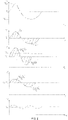
- the temperature T in an indoor environment generally follows a wave trend around the comfort temperature T c .
- the air conditioning device when the temperature is below the comfort value T c the air conditioning device is activated and exchanges heat in an indoor environment, increasing the temperature in the same indoor environment, through the circulation of the carrier fluid.
- the device When the environment temperature, instead, exceeds the comfort value T c , the device is deactivated in order to stop the circulation of the carrier fluid inside the circuit.
- the carrier fluid is heated to a preset operating temperature and therefore a certain amount of heat is transferred by the latter to the environment, even after the device has been stopped.
- the activation of the device will promote the heating of the carrier fluid, but the latter will reach the operating temperature only after a certain period of time, during which the environment will keep cooling.
- This effect is caused by the fact that the device and the environment have a certain inherent thermal inertia that generates an oscillating trend of the temperature of an indoor environment.
- the oscillation of the temperature ranges between two maximum temperature values, respectively an upper value T max and a lower value T min with respect to the comfort temperature T c , which can be the same or different from each other.
- the temperature curve determined in an indoor environment is not symmetrical and can feature different half waves, meaning that its trend above the comfort temperature T c can be different from its trend below said temperature, in particular the elements that can vary are the gradient and the duration of said half waves.
- the method includes also a step f) of calculation of the surface area A 1 subtended by a section of the temperature curve determined in step d) .
- the temperature section subjected to the calculation step e) has respective end points whose value corresponds to the comfort temperature T c and intermediate values corresponding to a higher temperature value compared to said comfort value T c .
- step f) includes the calculation of the surface area A 1 subtended by the upper half wave of the temperature curve, that is, associated with that specific section of the same that develops above the comfort temperature T c .
- the method includes a step g) of calculation of the surface area A 2 subtended by a section of the temperature curve determined in step d) which has respective end points whose value corresponds to the comfort temperature T c and intermediate values corresponding to a temperature value that is lower than said comfort value T c .
- step g) includes the calculation of the surface area A 2 subtended by the lower half wave of the temperature curve corresponding to the section of the same that develops below the comfort temperature T c .
- the surface area subtended by the temperature curve in a predefined time interval indicates the variation of the energy content of the system.
- the energy content of the system makes it possible to characterize the thermal power associated with the device in that specific operating condition (above or below the comfort temperature).
- the surface areas A 1, A 2 measured during steps f) and g) can be different.
- the successive step h) of the method includes the calculation of a fictitious temperature value T x , visible in the third diagram of Figure 2 , which therefore must be understood as a merely numerical value corresponding to the average value of the surface areas A 1 and A 2 around which the trend of an ideal temperature curve, also hypothetical and having a substantially sinusoidal shape, is developed.
- the fictitious temperature T x characterizes the energy content of the system, in other words the energy content of the heat introduced in the environment during a predefined and limited time substantially varies according to the environment itself, since the other variables that characterize the system (temperature of the walls, outdoor temperature, etc.) tend to be constant. As more clearly described below, this condition allows the system to tend towards a balanced situation during the repetition of the corrections of the thermal power introduced in the system.
- the ratio between the surface area subtended by the two half waves ( A 1 + A 2 ) and the area A c subtended by the curve of the comfort temperature T c expresses a value that is associated with the difference in thermal energy defined by the fictitious temperature T x and by the comfort temperature T c .
- the thermal energy Q introduced in the environment A corresponds to the value of the thermal energy that varies according to the ratio between the surface area subtended by the two half waves ( A 1 + A 2 ) and the area A c subtended by the curve of the comfort temperature T c , it will be possible to bring in the environment A an energy content that is substantially equal to that defined by the comfort temperature T c .
- this ideal curve has a sinusoidal trend around the fictitious value T x and an upper half wave whose surface area ( A 1 + A 2 ) / 2 and amplitude are equal to the surface area ( A 1 + A 2 ) / 2 and to the amplitude of the lower half wave.
- the area globally subtended by the two half waves ( A 1 + A 2 ) / 2 expressed as an absolute value, will be substantially equal to the sum ( A 1 + A 2 ) of the surface areas calculated in steps f) and g).
- the fictitious condition expressed by the ideal temperature curve refers to a situation of possible heat balance between the amount of heat that must be introduced in the environment and the amount of heat dispersed by the same due to the inevitable losses.
- T c characterizes the actual energy content of the system and makes it possible to calculate the exact amount of heat that must be supplied to the environment in order to compensate for the energy that the same environment dissipates due to the thermal losses during a discrete and predetermined time period.
- the ideal sinusoidal temperature curve makes it possible to express the heat balance in the case where the fictitious temperature T c must be reached and maintained at the reference point P inside the environment.
- the method comprises a step i) of calculation of the ratio between the surface area subtended by a section of the temperature curve determined during step f) and the surface area subtended by a section of the temperature curve determined during step g) with respect to the surface area subtended by the comfort temperature curve determined during said step c) .
- step j) of transfer of a predetermined amount of heat into the environment said amount of heat being suited to promote a variation of the thermal power introduced in the environment as a function of the calculation made during step h) and step i) .
- step j) there is also a step l) of comparison between the fictitious temperature value T x calculated during step h) and the comfort temperature set in step b).
- step i) In the case where said comparison does not give a positive result, that is, when the fictitious temperature value is different from the comfort value, during the execution of step i) there is a step m) during which the preceding steps from c) to i) are repeated.
- step m) the surface area subtended by the comfort temperature curve T c is calculated again (step c) ), the temperature trend of the indoor environment is determined (step d) ), the controlled activation/deactivation of the air conditioning device is promoted (step e) ) in order to calculate the surface area subtended by the sections of the temperature curve that develop above and below the comfort value T c (step f) and g) ) and then the fictitious temperature value T x is calculated (step h) ), successively promoting the comparison of the latter with the comfort value T c set by the user (step i) ).
- step m the activation time t a and the deactivation time t d of the air conditioning device can be different from those previously used during the execution of step e) .
- step m) the surface areas A 1 ', A 2 ' calculated during steps f) and g) have a value that is different from the previously calculated value, since the trend of the curve has changed with respect to the previous one.
- the fictitious temperature value T x ' calculated during step h) is different from the fictitious value T x calculated in a preceding time instant.
- Step m) will be carried out until the fictitious temperature value T x ' is substantially equal to the comfort value T c set by the user.
- the method includes a step n) during which the air conditioning device is selectively activated in order to transfer to the carrier fluid a predetermined quantity of thermal energy suited to promote a temperature variation as a function of the calculation carried out during steps h) and i).
- this temperature variation is associated with the reference point P.
- the step b) of the method can be configured to set respective comfort temperatures T c at a plurality of reference points P distributed in the environment A.
- the remaining steps c) - n) of the method will be carried out independently for each one of these points P, so as to determine respective thermal powers Q suited to exactly compensate for the losses associated with the environment at each reference point P.
- the method comprises a step o) during which the thermal power Q introduced in the environment is controlled by measuring the thermal differential ⁇ T associated with the carrier fluid respectively at the outlet and at the inlet of the circuit.
- this thermal differential ⁇ T is calculated at the supply opening and at the return opening of the carrier fluid that circulates inside the circuit.
- the method can include two distinct steps, indicated by the letters p) and q), during which a plurality of parameters not associated with the environment are measured.
- step m) (comparison between the fictitious temperature value and the comfort temperature value) it is possible to instantly measure a plurality of parameters associated with an area of the outdoor environment.
- the parameters associated with the external environment can be selected from the group including solar irradiation, wind intensity, outdoor temperature, humidity, atmospheric pressure etc.
- step q some vital parameters associated with one or more users present in an indoor environment are measured.
- the parameters measured during said step can be selected from the group including body temperature, heart rate, blood pressure, etc.
- the method includes also a step r) of storage of the thermal power value Q (referred to a predetermined time interval) calculated during step j) and of the instant values of the external and vital parameters respectively measured during steps p) and q) .
- step r) is carried out at the same time as step j) of transfer of the predetermined amount of heat into the environment A.
- step r) can be carried out when it is noticed that the external parameters affect the value of the thermal energy Q (referred to a predetermined time interval) necessary to maintain the temperature T inside the environment A at a value substantially equal to the comfort value T c .
- the method will make it possible to determine the amount of heat Q that the device must provide at the reference point P in order to obtain the comfort temperature T c in the conditions in which the parameters associated with the outdoor environment and with the user correspond to those previously stored.
- the thermal power Q calculated during step j) can assume different values as the external or vital parameters measured during steps p) and q) vary.
- the variation of the external parameters may cause a modification of the losses associated with the environment A, while the variation of the vital parameters of the user may cause the latter to perceive a different sensation in terms of hot/cold, this being a condition that can be modified by adjusting the heat introduced in the environment.
- the step r) makes it possible to associate the amount of heat needed by the environment to maintain the comfort temperature with a plurality of external or vital conditions, so that it is always possible to know in advance the overall thermal energy Q that must be generated by the air conditioning device when said conditions occur.
- the method must also comprise one or more steps following the determination of the thermal power necessary to guarantee the thermal balance and suited to promote a reduction in the amplitude of the sinusoidal curve through the reduction of the instants of activation of the air conditioning device.
- the thermal power introduced in the environment A remains substantially constant.
- the method comprises also a step s) of adjustment of the temperature curve T determined of an indoor environment A during the execution of step d) in order to make it substantially similar to the trend curve of the comfort temperature T c .
- step t) of modification of the temperature curve T in order to adapt it to the trend of the ideal sinusoidal curve of the temperature that is obtained when the fictitious temperature value calculated during said step i) coincides with the substantially idealized comfort value set by the user.
- step e) of controlled activation/deactivation of the air conditioning device is repeated during step s) .
- This forcing action can be applied to the trend of the temperature measured at a single reference point P or, alternatively, it may affect the temperature measured at several reference points P .
- step s) and following step t) there can be a step u) of reduction of the amplitude of the sinusoidal curve associated with the temperature T measured in an indoor environment A .
- the conditioning step u) is carried out before steps p) and q) of measurement of the parameters and can be carried out through a further execution of step e) of controlled activation/deactivation of the air conditioning device.
- the sinusoidal curve associated with the temperature curve may present reduced period and amplitude, so that it oscillates within a neighbourhood very near the comfort temperature.
- the thermal power Q introduced in the environment always corresponds to that calculated in the corresponding step I) of the method, even if it is its distribution over time that varies owing to the variation in the amplitude and period of the sinusoidal curve.
- steps t) and u) makes it possible to promote an increase in the maximum temperature perceived by one or more persons present inside the environment A and makes the temperature perceived by the latter more uniform in general, improving his/her feeling of well-being when he/she is of an indoor environment.
- the value of said thermal power makes it possible to compensate exactly for the thermal losses associated with said environment.
- the present method makes it possible to assess since the beginning the amount of heat that is necessary to heat or cool the environment in certain conditions.
- the air conditioning device will be activated in order to produce/remove the previously calculated amount of heat and introduce or remove it into/from the environment.
- the subject of the same includes a system for controlling the temperature of an indoor environment A .
- this system comprises at least one air conditioning device suited to promote the heating/cooling of the environment A through the forced circulation of a carrier fluid inside a circuit associated with the environment A .
- sensor means are also provided, which are suited to monitor the trend curve of the temperature T measured in at least one reference point P located in an indoor environment A and activation means associated with said at least one air conditioning device in order to promote its selective activation when the trend curve of the temperature measured by the sensor means has an instant value that is higher/lower than a predetermined value.
- the activation means are configured to selectively activate said air conditioning device according to the steps of the method previously described, so as to promote the transfer of a predetermined amount of thermal energy Q to the carrier fluid.
- the entity of this thermal energy Q is such as to promote, at the reference point P , a variation in the instant temperature as a function of the calculation made during step h) and step i) of the method described above.
Landscapes
- Engineering & Computer Science (AREA)
- Chemical & Material Sciences (AREA)
- Combustion & Propulsion (AREA)
- Mechanical Engineering (AREA)
- General Engineering & Computer Science (AREA)
- Signal Processing (AREA)
- Physics & Mathematics (AREA)
- Fuzzy Systems (AREA)
- Mathematical Physics (AREA)
- General Physics & Mathematics (AREA)
- Automation & Control Theory (AREA)
- Air Conditioning Control Device (AREA)
Claims (12)
- Verfahren zur Kontrolle der Temperatur eines Innenbereichs, folgende Schritte umfassend:a) Bereitstellung eines Klimageräts, das dazu geeignet ist, durch die Zwangszirkulation eines Trägerfluids in einem mit der Umgebung assoziierten Kreislauf die Heizung/Kühlung der Umgebung zu bewirken;b) Einstellung einer mit wenigstens einem in einem Innenbereich gewählten Bezugspunkt assoziierten Komforttemperatur;c) Berechnung des Oberflächenbereichs, der durch die dem Trend der besagten Komforttemperatur im zeitlichen Verlauf entsprechende Kurve unterspannt ist;d) Überwachung der Trendkurve der im zeitlichen Verlauf an dem besagten wenigstens einen Bezugspunkt gemessenen Temperatur;e) Aktivierung/Deaktivierung des Klimageräts, wenn der momentane Wert der während des besagten Schritts d) bestimmten Temperaturkurve höher/niedriger ist als der in Schritt b) eingestellte Komfortwert, wobei der besagte Schritt e) mit einer vorbestimmten Dauer der Aktivierungs-/Deaktivierungszeiten ausgeführt wird;f) Berechnung der durch einen Abschnitt der in Schritt d) bestimmten Temperaturkurve unterspannten Oberfläche, wobei der besagte Kurvenabschnitt jeweils Endpunkte aufweist, deren Wert der Komforttemperatur entspricht, und Zwischenpunkte aufweist, die im Vergleich zur Komforttemperatur höheren Temperaturwerten entsprechen;g) Berechnung der durch einen Abschnitt der in Schritt d) bestimmten Temperaturkurve unterspannten Oberfläche, wobei der besagte Kurvenabschnitt jeweils Endpunkte aufweist, deren Wert der Komforttemperatur entspricht, und Zwischenpunkte aufweist, die im Vergleich zur Komforttemperatur niedrigeren Temperaturwerten entsprechen;h) Berechnung eines fiktiven Temperaturwerts, welcher dem Durchschnittswert einer idealen sinusförmigen Temperaturkurve entspricht, wobei die besagte ideale sinusförmige Temperaturkurve eine Amplitude aufweist, die dazu geeignet ist, die Summe der in besagtem Schritt f) und in besagtem Schritt g) berechneten Oberflächen auf den zwei Halbwellen zu verteilen;i) Berechnung des Verhältnisses zwischen der Summe aus der durch einen Abschnitt der in Schritt f) bestimmten Temperaturkurve überspannten Oberfläche und der durch einen Abschnitt der in Schritt g) bestimmten Temperaturkurve überspannten Oberfläche einerseits und der durch die in Schritt g) bestimmten Komforttemperaturkurve unterspannten Oberfläche andererseits;j) Übertragung einer vorbestimmten Wärmemenge in die Umgebung, wobei die besagte vorbestimmte Wärmemenge dazu geeignet ist, eine Veränderung der Wärmeleistung zu bewirken, die in Abhängigkeit der in Schritt h) und in Schritt i) ausgeführten Berechnung der Umgebung zugeführt wurde;wobei der besagte Schritt j) einen Schritt n) der selektiven Aktivierung des Klimageräts umfasst, um eine vorbestimmte Menge Wärmeenergie an das besagte Trägerfluid zu übertragen, wobei die besagte Menge Wärmeenergie dazu geeignet ist, in Abhängigkeit der in Schritt h) und in Schritt i) ausgeführten Berechnung eine Veränderung der momentanen Temperatur zu bewirken, wobei die besagte Temperaturveränderung mit dem besagten wenigstens einen Bezugspunkt assoziiert ist.
- Verfahren nach Patentanspruch 1, dadurch gekennzeichnet, dass der besagte Schritt der Übertragung j) einen Schritt I) des Vergleichs zwischen dem besagten fiktiven, in besagtem Schritt h) berechneten Wert und der in besagtem Schritt b) eingestellten Komforttemperatur umfasst.
- Verfahren nach Patentanspruch 2, dadurch gekennzeichnet, dass der besagte Schritt der Übertragung j) einen Schritt m) umfasst, in dem die Schritte von c) bis i) wiederholt werden, wenn der besagte fiktive Wert von der Komforttemperatur abweicht, wobei der Schritt e) mit anderen Aktivierungs-/Deaktivierungszeiten ausgeführt wird.
- Verfahren nach Patentanspruch 2, dadurch gekennzeichnet, dass es einen Schritt o) der Kontrolle der der Umgebung zugeführten Wärmeleistung umfasst, wobei der besagte Schritt o) durch Messung der Differenz zwischen der Temperatur des Trägerfluids am Einlass und der Temperatur des Trägerfluids am Auslass des besagten Kreislaufs erfolgt.
- Verfahren nach einem oder mehreren der vorstehenden Patentansprüche, dadurch gekennzeichnet, dass es einen Schritt p) der momentanen Messung einer Vielzahl von in einem Außenbereich mit dem Raum assoziierten Parametern umfasst.
- Verfahren nach Patentanspruch 5, dadurch gekennzeichnet, dass in besagtem Schritt p) einige die Witterung betreffenden Parameter gemessen werden, die aus der Gruppe ausgewählt werden, die Sonneneinstrahlung, Windstärke, Außentemperatur, Feuchtigkeit, Luftdruck und weitere, ähnliche Parameter umfasst.
- Verfahren nach Patentanspruch 5 oder 6, dadurch gekennzeichnet, dass es einen Schritt q) der Messung einer Vielzahl von mit einem oder mehreren, im Innenbereich anwesenden Benutzern assoziierten vitalen Parametern umfasst.
- Verfahren nach einem oder mehreren der vorstehenden Patentansprüche, dadurch gekennzeichnet, dass es einen Schritt r) der Speicherung des in Schritt j) berechneten Wärmeleistungswerts und jeweils des momentanen Werts der in besagtem Schritt p) gemessenen und mit dem Außenbereich assoziierten Parameter und/oder des Werts der in besagtem Schritt q) gemessenen vitalen Parameter umfasst.
- Verfahren nach einem oder mehreren der vorstehenden Patentansprüche, dadurch gekennzeichnet, dass es einen Schritt s) der Anpassung der in besagtem Schritt d) bestimmten Temperaturkurve umfasst, wobei der besagte Schritt der Anpassung s) unter Zusammenwirken mit dem besagten Schritt e) der selektiven Aktivierung/Deaktivierung des Klimageräts ausgeführt wird, um die Temperaturkurve im Wesentlichen der Komforttemperaturkurve ähnlich zu machen.
- Verfahren nach Patentanspruch 9, dadurch gekennzeichnet, dass der besagte Schritt s) einen Schritt t) der Veränderung der Temperaturkurve eines Innenbereichs umfasst, welcher unter Zusammenwirken mit dem besagten Schritt e) der selektiven Aktivierung/Deaktivierung des Klimageräts ausgeführt wird, um die Temperaturkurve zu ändern und im Wesentlichen der Sinusform der besagten idealen Temperaturkurve ähnlich zu machen, welche erzielt wird, wenn der besagte, in besagtem Schritt h) berechnete fiktive Durchschnittswert mit dem Wert der in besagtem Schritt b) eingestellten Komforttemperatur übereinstimmt.
- Verfahren nach Patentanspruch 10, dadurch gekennzeichnet, dass der besagte Schritt s) der Anpassung nach dem besagten Schritt t) der Veränderung einen Schritt u) umfasst, in dem die Amplitude der mit der Temperatur des Innenbereichs assoziierten, sinusförmigen Kurve reduziert wird, wobei der besagte Schritt u) der Amplitudenreduzierung unter Zusammenwirken mit dem besagten Schritt e) der selektiven Aktivierung/Deaktivierung des Klimageräts ausgeführt wird.
- System zur Kontrolle der Temperatur eines Innenbereichs, wobei das besagte System Folgendes umfasst:- wenigstens ein Klimagerät, dazu geeignet, durch die Zwangszirkulation eines Trägerfluids in einem mit der Umgebung assoziierten Kreislauf die Heizung/Kühlung der Umgebung zu bewirken;- Sensormittel, dazu geeignet, die Trendkurve der an wenigstens einem Bezugspunkt gemessenen Temperatur zu überwachen;- Mit dem besagten, wenigstens einen Klimagerät assoziierte Aktivierungsmittel zur selektiven Aktivierung desselben, wenn die Trendkurve der durch die besagten Sensormittel gemessenen Temperatur einen momentanen Wert aufweist, der höher/niedriger ist als ein vorbestimmter Wert;dadurch gekennzeichnet, dass die besagten Aktivierungsmittel dazu konfiguriert sind, selektiv das besagte wenigstens eine Klimagerät den Schritten des Verfahrens nach einem oder mehreren der vorstehenden Patentansprüche folgend zu aktivieren.
Applications Claiming Priority (2)
| Application Number | Priority Date | Filing Date | Title |
|---|---|---|---|
| IT201800007051 | 2018-07-10 | ||
| PCT/IB2019/055838 WO2020012355A1 (en) | 2018-07-10 | 2019-07-09 | Indoor environmental control system and method controlling the same |
Publications (2)
| Publication Number | Publication Date |
|---|---|
| EP3821177A1 EP3821177A1 (de) | 2021-05-19 |
| EP3821177B1 true EP3821177B1 (de) | 2022-08-31 |
Family
ID=63834393
Family Applications (1)
| Application Number | Title | Priority Date | Filing Date |
|---|---|---|---|
| EP19758806.4A Active EP3821177B1 (de) | 2018-07-10 | 2019-07-09 | Innenraum-klimatisierungssystem und verfahren zu dessen steuerung |
Country Status (2)
| Country | Link |
|---|---|
| EP (1) | EP3821177B1 (de) |
| WO (1) | WO2020012355A1 (de) |
Families Citing this family (7)
| Publication number | Priority date | Publication date | Assignee | Title |
|---|---|---|---|---|
| CN109612034B (zh) * | 2018-11-30 | 2022-04-12 | 广东美的制冷设备有限公司 | 温度控制方法、装置以及存储介质 |
| CN114547125B (zh) * | 2020-11-24 | 2025-03-14 | 远东科技大学 | 调整环控设备的方法及建立环控设备的比对数据库方法 |
| IT202000031010A1 (it) * | 2020-12-16 | 2022-06-16 | Tekiin S R L | Sistema per il riscaldamento di un ambiente |
| CN114688708A (zh) * | 2020-12-29 | 2022-07-01 | 广东美的制冷设备有限公司 | 空调器的控制方法、装置、空调器及存储介质 |
| IT202100005528A1 (it) * | 2021-03-09 | 2022-09-09 | Tekiin S R L | Metodo per la regolazione della temperatura all’interno di un ambiente |
| CN116643602B (zh) * | 2023-04-07 | 2025-10-28 | 武汉汉立制冷科技股份有限公司 | 一种激光制冷系统控制温差自适应修正方法 |
| CN117663351B (zh) * | 2023-12-29 | 2024-06-21 | 山东凯丰节能科技股份有限公司 | 一种户外大型空调机集成控制系统 |
Family Cites Families (5)
| Publication number | Priority date | Publication date | Assignee | Title |
|---|---|---|---|---|
| US8190273B1 (en) * | 2008-04-18 | 2012-05-29 | Federspiel Corporation | Method and apparatus for controlling fans in heating, ventilating, and air-conditioning systems |
| BR112012014622A2 (pt) * | 2009-12-16 | 2019-05-14 | Commonwealth Scientific And Industrial Research Organisation | método de controle de sistema de aquecimento, ventilação e condicionamento de ar (hvac) de um edifício |
| US10077928B2 (en) * | 2012-06-21 | 2018-09-18 | Mitsubishi Electric Corporation | Air-conditioning system and control method for air-conditioning system |
| WO2016194190A1 (ja) * | 2015-06-04 | 2016-12-08 | 三菱電機株式会社 | ヒートポンプ利用システムの制御装置及びそれを備えたヒートポンプ利用システム |
| CN106288157A (zh) * | 2016-08-05 | 2017-01-04 | 珠海格力电器股份有限公司 | 一种机组使用效果的评价方法及装置 |
-
2019
- 2019-07-09 WO PCT/IB2019/055838 patent/WO2020012355A1/en not_active Ceased
- 2019-07-09 EP EP19758806.4A patent/EP3821177B1/de active Active
Also Published As
| Publication number | Publication date |
|---|---|
| WO2020012355A1 (en) | 2020-01-16 |
| EP3821177A1 (de) | 2021-05-19 |
Similar Documents
| Publication | Publication Date | Title |
|---|---|---|
| EP3821177A1 (de) | System und verfahren zur steuerung der innenraumklimatisierung | |
| USRE50110E1 (en) | Control systems and methods for HVAC equipment with fluid loop thermal energy storage | |
| US11281168B2 (en) | Central plant control system based on load prediction through mass storage model | |
| RU2573378C2 (ru) | Устройство и способ управления открытием клапана в системе hvac | |
| KR101162582B1 (ko) | 습도 추정 장치 및 습도 추정 방법 | |
| US9046274B2 (en) | Method and device for setting a temperature control system | |
| CN108613326B (zh) | 空调系统及其智能调节控制方法、装置、计算机设备 | |
| EP2716989A1 (de) | Temperaturregelungssystem, klimaanlagensystem und steuerverfahren dafür | |
| EP2511618A2 (de) | Klimatisierungseinrichtung und Klimatisierungsverfahren | |
| EP3561406B1 (de) | Wärmeaktivsteuerungsverfahren und -vorrichtung für eine klimaanlage | |
| EP3306216B1 (de) | Steuerungsvorrichtung für wärmepumpenverwendendes system und damit ausgestattetes wärmepumpenverwendendes system | |
| JP2009031866A (ja) | 流量制御バルブおよび流量制御方法 | |
| CN105650811A (zh) | 控制空调室内机的方法和装置 | |
| CN105423500A (zh) | 空调器的控制方法、空调器的控制系统和空调器 | |
| CN106196474A (zh) | 空调智能控制方法 | |
| RU2570784C2 (ru) | Способ и установка регулирования температуры в здании | |
| US20150177748A1 (en) | Control system and method for energy smart fan | |
| EP3098529B1 (de) | Koordinierte steuerung von hlk-systemen mittels aggregiertem systembedarf | |
| EP3382490B1 (de) | Verfahren zur steuerung eines hydronischen heizsystems in mehreren räumen | |
| WO2022234506A1 (en) | Method for controlling the temperature of an indoor environment | |
| JP2020159671A (ja) | 放射空調システム及びその制御方法 | |
| CN118565036A (zh) | 空调器的控制方法、空调器以及计算机可读存储介质 | |
| EP3662212B1 (de) | Verfahren zur regelung einer konditionierungsvorrichtung | |
| FI126110B (fi) | Menetelmä, laitteisto ja tietokoneohjelmatuote toimilaitteen ohjaamiseksi lämpötilan säätelyssä | |
| IT202100005528A1 (it) | Metodo per la regolazione della temperatura all’interno di un ambiente |
Legal Events
| Date | Code | Title | Description |
|---|---|---|---|
| STAA | Information on the status of an ep patent application or granted ep patent |
Free format text: STATUS: UNKNOWN |
|
| STAA | Information on the status of an ep patent application or granted ep patent |
Free format text: STATUS: THE INTERNATIONAL PUBLICATION HAS BEEN MADE |
|
| PUAI | Public reference made under article 153(3) epc to a published international application that has entered the european phase |
Free format text: ORIGINAL CODE: 0009012 |
|
| STAA | Information on the status of an ep patent application or granted ep patent |
Free format text: STATUS: REQUEST FOR EXAMINATION WAS MADE |
|
| 17P | Request for examination filed |
Effective date: 20210209 |
|
| AK | Designated contracting states |
Kind code of ref document: A1 Designated state(s): AL AT BE BG CH CY CZ DE DK EE ES FI FR GB GR HR HU IE IS IT LI LT LU LV MC MK MT NL NO PL PT RO RS SE SI SK SM TR |
|
| DAV | Request for validation of the european patent (deleted) | ||
| DAX | Request for extension of the european patent (deleted) | ||
| GRAP | Despatch of communication of intention to grant a patent |
Free format text: ORIGINAL CODE: EPIDOSNIGR1 |
|
| STAA | Information on the status of an ep patent application or granted ep patent |
Free format text: STATUS: GRANT OF PATENT IS INTENDED |
|
| INTG | Intention to grant announced |
Effective date: 20220307 |
|
| GRAS | Grant fee paid |
Free format text: ORIGINAL CODE: EPIDOSNIGR3 |
|
| GRAA | (expected) grant |
Free format text: ORIGINAL CODE: 0009210 |
|
| STAA | Information on the status of an ep patent application or granted ep patent |
Free format text: STATUS: THE PATENT HAS BEEN GRANTED |
|
| AK | Designated contracting states |
Kind code of ref document: B1 Designated state(s): AL AT BE BG CH CY CZ DE DK EE ES FI FR GB GR HR HU IE IS IT LI LT LU LV MC MK MT NL NO PL PT RO RS SE SI SK SM TR |
|
| REG | Reference to a national code |
Ref country code: CH Ref legal event code: EP Ref country code: GB Ref legal event code: FG4D |
|
| REG | Reference to a national code |
Ref country code: AT Ref legal event code: REF Ref document number: 1515565 Country of ref document: AT Kind code of ref document: T Effective date: 20220915 Ref country code: DE Ref legal event code: R096 Ref document number: 602019019022 Country of ref document: DE |
|
| REG | Reference to a national code |
Ref country code: IE Ref legal event code: FG4D |
|
| REG | Reference to a national code |
Ref country code: LT Ref legal event code: MG9D |
|
| REG | Reference to a national code |
Ref country code: NL Ref legal event code: MP Effective date: 20220831 |
|
| PG25 | Lapsed in a contracting state [announced via postgrant information from national office to epo] |
Ref country code: SE Free format text: LAPSE BECAUSE OF FAILURE TO SUBMIT A TRANSLATION OF THE DESCRIPTION OR TO PAY THE FEE WITHIN THE PRESCRIBED TIME-LIMIT Effective date: 20220831 Ref country code: RS Free format text: LAPSE BECAUSE OF FAILURE TO SUBMIT A TRANSLATION OF THE DESCRIPTION OR TO PAY THE FEE WITHIN THE PRESCRIBED TIME-LIMIT Effective date: 20220831 Ref country code: NO Free format text: LAPSE BECAUSE OF FAILURE TO SUBMIT A TRANSLATION OF THE DESCRIPTION OR TO PAY THE FEE WITHIN THE PRESCRIBED TIME-LIMIT Effective date: 20221130 Ref country code: LV Free format text: LAPSE BECAUSE OF FAILURE TO SUBMIT A TRANSLATION OF THE DESCRIPTION OR TO PAY THE FEE WITHIN THE PRESCRIBED TIME-LIMIT Effective date: 20220831 Ref country code: LT Free format text: LAPSE BECAUSE OF FAILURE TO SUBMIT A TRANSLATION OF THE DESCRIPTION OR TO PAY THE FEE WITHIN THE PRESCRIBED TIME-LIMIT Effective date: 20220831 Ref country code: FI Free format text: LAPSE BECAUSE OF FAILURE TO SUBMIT A TRANSLATION OF THE DESCRIPTION OR TO PAY THE FEE WITHIN THE PRESCRIBED TIME-LIMIT Effective date: 20220831 |
|
| REG | Reference to a national code |
Ref country code: AT Ref legal event code: MK05 Ref document number: 1515565 Country of ref document: AT Kind code of ref document: T Effective date: 20220831 |
|
| PG25 | Lapsed in a contracting state [announced via postgrant information from national office to epo] |
Ref country code: PL Free format text: LAPSE BECAUSE OF FAILURE TO SUBMIT A TRANSLATION OF THE DESCRIPTION OR TO PAY THE FEE WITHIN THE PRESCRIBED TIME-LIMIT Effective date: 20220831 Ref country code: IS Free format text: LAPSE BECAUSE OF FAILURE TO SUBMIT A TRANSLATION OF THE DESCRIPTION OR TO PAY THE FEE WITHIN THE PRESCRIBED TIME-LIMIT Effective date: 20221231 Ref country code: HR Free format text: LAPSE BECAUSE OF FAILURE TO SUBMIT A TRANSLATION OF THE DESCRIPTION OR TO PAY THE FEE WITHIN THE PRESCRIBED TIME-LIMIT Effective date: 20220831 Ref country code: GR Free format text: LAPSE BECAUSE OF FAILURE TO SUBMIT A TRANSLATION OF THE DESCRIPTION OR TO PAY THE FEE WITHIN THE PRESCRIBED TIME-LIMIT Effective date: 20221201 |
|
| PG25 | Lapsed in a contracting state [announced via postgrant information from national office to epo] |
Ref country code: SM Free format text: LAPSE BECAUSE OF FAILURE TO SUBMIT A TRANSLATION OF THE DESCRIPTION OR TO PAY THE FEE WITHIN THE PRESCRIBED TIME-LIMIT Effective date: 20220831 Ref country code: RO Free format text: LAPSE BECAUSE OF FAILURE TO SUBMIT A TRANSLATION OF THE DESCRIPTION OR TO PAY THE FEE WITHIN THE PRESCRIBED TIME-LIMIT Effective date: 20220831 Ref country code: PT Free format text: LAPSE BECAUSE OF FAILURE TO SUBMIT A TRANSLATION OF THE DESCRIPTION OR TO PAY THE FEE WITHIN THE PRESCRIBED TIME-LIMIT Effective date: 20230102 Ref country code: ES Free format text: LAPSE BECAUSE OF FAILURE TO SUBMIT A TRANSLATION OF THE DESCRIPTION OR TO PAY THE FEE WITHIN THE PRESCRIBED TIME-LIMIT Effective date: 20220831 Ref country code: DK Free format text: LAPSE BECAUSE OF FAILURE TO SUBMIT A TRANSLATION OF THE DESCRIPTION OR TO PAY THE FEE WITHIN THE PRESCRIBED TIME-LIMIT Effective date: 20220831 Ref country code: CZ Free format text: LAPSE BECAUSE OF FAILURE TO SUBMIT A TRANSLATION OF THE DESCRIPTION OR TO PAY THE FEE WITHIN THE PRESCRIBED TIME-LIMIT Effective date: 20220831 Ref country code: AT Free format text: LAPSE BECAUSE OF FAILURE TO SUBMIT A TRANSLATION OF THE DESCRIPTION OR TO PAY THE FEE WITHIN THE PRESCRIBED TIME-LIMIT Effective date: 20220831 |
|
| PG25 | Lapsed in a contracting state [announced via postgrant information from national office to epo] |
Ref country code: SK Free format text: LAPSE BECAUSE OF FAILURE TO SUBMIT A TRANSLATION OF THE DESCRIPTION OR TO PAY THE FEE WITHIN THE PRESCRIBED TIME-LIMIT Effective date: 20220831 Ref country code: EE Free format text: LAPSE BECAUSE OF FAILURE TO SUBMIT A TRANSLATION OF THE DESCRIPTION OR TO PAY THE FEE WITHIN THE PRESCRIBED TIME-LIMIT Effective date: 20220831 |
|
| REG | Reference to a national code |
Ref country code: DE Ref legal event code: R097 Ref document number: 602019019022 Country of ref document: DE |
|
| PG25 | Lapsed in a contracting state [announced via postgrant information from national office to epo] |
Ref country code: NL Free format text: LAPSE BECAUSE OF FAILURE TO SUBMIT A TRANSLATION OF THE DESCRIPTION OR TO PAY THE FEE WITHIN THE PRESCRIBED TIME-LIMIT Effective date: 20220831 Ref country code: AL Free format text: LAPSE BECAUSE OF FAILURE TO SUBMIT A TRANSLATION OF THE DESCRIPTION OR TO PAY THE FEE WITHIN THE PRESCRIBED TIME-LIMIT Effective date: 20220831 |
|
| PLBE | No opposition filed within time limit |
Free format text: ORIGINAL CODE: 0009261 |
|
| STAA | Information on the status of an ep patent application or granted ep patent |
Free format text: STATUS: NO OPPOSITION FILED WITHIN TIME LIMIT |
|
| P01 | Opt-out of the competence of the unified patent court (upc) registered |
Effective date: 20230531 |
|
| 26N | No opposition filed |
Effective date: 20230601 |
|
| PG25 | Lapsed in a contracting state [announced via postgrant information from national office to epo] |
Ref country code: SI Free format text: LAPSE BECAUSE OF FAILURE TO SUBMIT A TRANSLATION OF THE DESCRIPTION OR TO PAY THE FEE WITHIN THE PRESCRIBED TIME-LIMIT Effective date: 20220831 |
|
| REG | Reference to a national code |
Ref country code: DE Ref legal event code: R119 Ref document number: 602019019022 Country of ref document: DE |
|
| PG25 | Lapsed in a contracting state [announced via postgrant information from national office to epo] |
Ref country code: MC Free format text: LAPSE BECAUSE OF FAILURE TO SUBMIT A TRANSLATION OF THE DESCRIPTION OR TO PAY THE FEE WITHIN THE PRESCRIBED TIME-LIMIT Effective date: 20220831 |
|
| PG25 | Lapsed in a contracting state [announced via postgrant information from national office to epo] |
Ref country code: MC Free format text: LAPSE BECAUSE OF FAILURE TO SUBMIT A TRANSLATION OF THE DESCRIPTION OR TO PAY THE FEE WITHIN THE PRESCRIBED TIME-LIMIT Effective date: 20220831 |
|
| REG | Reference to a national code |
Ref country code: CH Ref legal event code: PL |
|
| REG | Reference to a national code |
Ref country code: BE Ref legal event code: MM Effective date: 20230731 |
|
| PG25 | Lapsed in a contracting state [announced via postgrant information from national office to epo] |
Ref country code: LU Free format text: LAPSE BECAUSE OF NON-PAYMENT OF DUE FEES Effective date: 20230709 |
|
| GBPC | Gb: european patent ceased through non-payment of renewal fee |
Effective date: 20230709 |
|
| PG25 | Lapsed in a contracting state [announced via postgrant information from national office to epo] |
Ref country code: LU Free format text: LAPSE BECAUSE OF NON-PAYMENT OF DUE FEES Effective date: 20230709 |
|
| REG | Reference to a national code |
Ref country code: IE Ref legal event code: MM4A |
|
| PG25 | Lapsed in a contracting state [announced via postgrant information from national office to epo] |
Ref country code: DE Free format text: LAPSE BECAUSE OF NON-PAYMENT OF DUE FEES Effective date: 20240201 Ref country code: CH Free format text: LAPSE BECAUSE OF NON-PAYMENT OF DUE FEES Effective date: 20230731 Ref country code: GB Free format text: LAPSE BECAUSE OF NON-PAYMENT OF DUE FEES Effective date: 20230709 |
|
| PG25 | Lapsed in a contracting state [announced via postgrant information from national office to epo] |
Ref country code: IT Free format text: LAPSE BECAUSE OF FAILURE TO SUBMIT A TRANSLATION OF THE DESCRIPTION OR TO PAY THE FEE WITHIN THE PRESCRIBED TIME-LIMIT Effective date: 20220831 Ref country code: FR Free format text: LAPSE BECAUSE OF NON-PAYMENT OF DUE FEES Effective date: 20230731 Ref country code: BE Free format text: LAPSE BECAUSE OF NON-PAYMENT OF DUE FEES Effective date: 20230731 |
|
| PG25 | Lapsed in a contracting state [announced via postgrant information from national office to epo] |
Ref country code: IE Free format text: LAPSE BECAUSE OF NON-PAYMENT OF DUE FEES Effective date: 20230709 |
|
| PG25 | Lapsed in a contracting state [announced via postgrant information from national office to epo] |
Ref country code: IE Free format text: LAPSE BECAUSE OF NON-PAYMENT OF DUE FEES Effective date: 20230709 |
|
| PG25 | Lapsed in a contracting state [announced via postgrant information from national office to epo] |
Ref country code: BG Free format text: LAPSE BECAUSE OF FAILURE TO SUBMIT A TRANSLATION OF THE DESCRIPTION OR TO PAY THE FEE WITHIN THE PRESCRIBED TIME-LIMIT Effective date: 20220831 |
|
| PG25 | Lapsed in a contracting state [announced via postgrant information from national office to epo] |
Ref country code: BG Free format text: LAPSE BECAUSE OF FAILURE TO SUBMIT A TRANSLATION OF THE DESCRIPTION OR TO PAY THE FEE WITHIN THE PRESCRIBED TIME-LIMIT Effective date: 20220831 |
|
| PG25 | Lapsed in a contracting state [announced via postgrant information from national office to epo] |
Ref country code: CY Free format text: LAPSE BECAUSE OF FAILURE TO SUBMIT A TRANSLATION OF THE DESCRIPTION OR TO PAY THE FEE WITHIN THE PRESCRIBED TIME-LIMIT; INVALID AB INITIO Effective date: 20190709 |
|
| PG25 | Lapsed in a contracting state [announced via postgrant information from national office to epo] |
Ref country code: HU Free format text: LAPSE BECAUSE OF FAILURE TO SUBMIT A TRANSLATION OF THE DESCRIPTION OR TO PAY THE FEE WITHIN THE PRESCRIBED TIME-LIMIT; INVALID AB INITIO Effective date: 20190709 |
|
| PG25 | Lapsed in a contracting state [announced via postgrant information from national office to epo] |
Ref country code: TR Free format text: LAPSE BECAUSE OF FAILURE TO SUBMIT A TRANSLATION OF THE DESCRIPTION OR TO PAY THE FEE WITHIN THE PRESCRIBED TIME-LIMIT Effective date: 20220831 |