EP3821764B1 - Système de pied pour parties de meubles et d'articles d'ameublement avec mise à niveau de réglage avant - Google Patents
Système de pied pour parties de meubles et d'articles d'ameublement avec mise à niveau de réglage avant Download PDFInfo
- Publication number
- EP3821764B1 EP3821764B1 EP20216634.4A EP20216634A EP3821764B1 EP 3821764 B1 EP3821764 B1 EP 3821764B1 EP 20216634 A EP20216634 A EP 20216634A EP 3821764 B1 EP3821764 B1 EP 3821764B1
- Authority
- EP
- European Patent Office
- Prior art keywords
- foot
- base
- floor
- furniture
- hole
- Prior art date
- Legal status (The legal status is an assumption and is not a legal conclusion. Google has not performed a legal analysis and makes no representation as to the accuracy of the status listed.)
- Active
Links
Images



Classifications
-
- A—HUMAN NECESSITIES
- A47—FURNITURE; DOMESTIC ARTICLES OR APPLIANCES; COFFEE MILLS; SPICE MILLS; SUCTION CLEANERS IN GENERAL
- A47B—TABLES; DESKS; OFFICE FURNITURE; CABINETS; DRAWERS; GENERAL DETAILS OF FURNITURE
- A47B91/00—Feet for furniture in general
- A47B91/02—Adjustable feet
- A47B91/022—Adjustable feet using screw means
- A47B91/028—Means for rotational adjustment on a non-rotational foot
Definitions
- the present invention relates to a foot system for parts of furniture and furnishing items with front adjustment levelling.
- This position is particularly unsuitable for maneuvering, to the extent that it is difficult to insert the tool in the actuating point and rotate it without his hand interfering with the floor.
- the general objective of the present invention is therefore to provide a foot system for parts of furniture and furnishing items with front adjustment levelling capable of solving the above drawbacks of the known art in an extremely simple, economical and particularly functional manner.
- a further objective of the present invention is to provide a foot system for parts of furniture and furnishing items with front adjustment levelling with extremely reduced encumbrances and with improved access from outside the furniture.
- Another objective of the present invention is to provide a foot system for parts of furniture and furnishing items with front adjustment levelling also for specific technical destinations such as refrigerator bases.
- this shows in a raised side view, a foot system for parts of furniture and furnishing items with front adjustment levelling according to the invention.
- a foot 11 is positioned between a base or bottom 12 of a piece of furniture and a floor P in a space reduced in height H, left by the arrangement of the parts.
- the foot 11 which contains in its interior an adjustment mechanism in height, has a hole 13 for the passage of a maneuvering tool 14.
- This hole 13 is formed in the body of the foot 11 in a lower area which is situated close to the floor P, opposite the base 12 of the furniture.
- the foot 11 is of the telescopic type and comprises a lower fixed part 17f with respect to the floor P and an upper movable part 17m integral with the base 12 of the furniture and which can be moved with it during the adjustment.
- the actuating point of the adjustment mechanism (coinciding with the hole 13) is adjacent to the floor P, positioned at a lower free end of the foot 11 in the fixed part 17f of the foot 11 resting on the floor P.
- the foot 11 is positioned with one of its axes X in a retracted position of a space R with respect to a front part of the furniture or base 12.
- the maneuvering tool 14 can be tilted by an angle ⁇ with respect to the floor P indicated as the maneuvering angle of the adjustment mechanism.
- the angle ⁇ is in relation to the ratio existing between the retracted space R of the axis X of the foot 11 with respect to the front part of the furniture and the space H existing between the base 12 of the furniture and the floor P.
- Said angle ⁇ preferably ranges from 0° to 40°, preferably 30°.
- the foot 11 in its upper movable part 17m at one of its free ends, provides a flange 18 which is provided with one or more pins 19. Said pins 19 are inserted in specific seats 23 formed in the base 12 which help in orienting the foot in its insertion phase between the base 12 and the floor P.
- This very particular and new arrangement allows a greater maneuvering angle ⁇ for the tool 14 with respect to that possible with the normal feet currently used. This makes it possible to reach the actuating point avoiding an edge S of the base 12 of the front of the furniture, in any case maintaining sufficient space for the operator's hand between the tool 14 and the floor P.
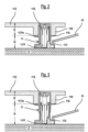
- Figures 2 and 3 show, in two raised side views, a second embodiment of foot system for parts of furniture and furnishing items with front adjustment levelling.
- Figures 2 and 3 show two different positions, one lowered and the other raised, for example between a refrigerator base 112 and a floor P.
- a flange 118 has been formed in an upper movable part 117m of the foot 11, which is abutted beneath the extension 116 ensuring better support between the parts.
- the lower fixed part 117f of the foot is that which gives the system stability and is where the actuating point or hole 113 of the adjustment mechanism is situated, in a position close to or adjacent to the floor P.
- Figures 4 and 5 also show in a further embodiment of the system in which the foot 11 is positioned between a bottom 212 of the furniture and the floor P.
- a wide flange 218 is provided in the upper movable part 217m of the body of the foot 11.
- This flange 218 is also provided with one or more pins 219 positioned in seats 223 which help in orienting the foot during its insertion phase in the seat 215.
- Said adjustment mechanism is arranged in two half-shells 24, 25 positioned inside the lower fixed part 217f and the upper movable part 217m of the foot 11.
- the two half-shells house 24,25 in the lower part, a pinion 26 free to rotate, which is coupled with a toothed crown 27, also free to rotate.
- the toothed crown 27 is positioned at an end of a threaded screw 28 on which a sleeve 29 is housed, slidingly guided in the above half-shells 24, 25.
- An upper shaped end 30 of the sleeve 29 is abutted in an internal base portion 31 of the upper movable part 217m of the foot 11.
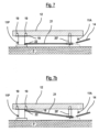
- Figures 6, 6b and 7, 7b are pairs of raised side views of a fourth embodiment of a foot system for parts of furniture and furnishing items with front adjustment levelling with adjustment on rear feet in two different positions.
- figures 6 and 6b show a front foot 11A and a rear foot 11P.
- the front foot 11A provides a hook extension 20 integrated in the same for housing an end portion of a maneuvering return rod 21 for adjusting the rear foot 11P.
- the return rod 21 is inserted in a maneuvering point 22 or hole formed in the rear foot 11P in a lower position.
- Figure 6b shows a second example in which the return rod 21 is inserted in a maneuvering point 22 or hole formed in the rear foot 11P in an upper position.
- the hook extension 20 is integrated with the front foot 11A.
- the return rod 21 is fixed, in the front, in the front foot 11A, in a position close to the floor P.
- the further figures 7 and 7b also show a front foot 11A and a rear foot 11P with a maneuvering return rod 21 for adjusting the rear foot 11P.
- a hook extension 20' is provided, which extends from the base 12, constrained to the same, and is associated (cooperates) with the front foot 11A for housing an end portion of the maneuvering return rod 21.
- figure 7 also shows how the return rod 21 is inserted in a maneuvering point 22 or hole formed in the rear foot 11P in a lower position.
- Figure 7b shows how the return rod 21 is inserted in a maneuvering point 22 or hole formed in the rear foot 11P in an upper position.
Landscapes
- Legs For Furniture In General (AREA)
Claims (8)
- Système de pied pour parties de meubles et d'articles d'ameublement avec une base ou un fond (12) avec mise à niveau à réglage avant, dans lequel au moins un pied (11) est configuré pour être positionné entre la base ou le fond (12) d'une partie de meuble et un sol (P) dans un espace réduit en hauteur (H), ledit pied (11) contenant à l'intérieur un mécanisme de réglage de hauteur actionné à partir d'un trou ou d'un point d'actionnement (13, 113, 213) au moyen d'un outil de manoeuvre (14), dans lequel ledit pied (11) est de type télescopique et comprend une partie inférieure (17f, 117f, 217f) destinée à reposer sur le sol et à être fixé par rapport audit sol (P) lors de l'utilisation dans des parties de meubles et d'articles d'ameublement, et une partie supérieure mobile (17m, 117m, 217m) destinée à faire partie intégrante de ladite base (12) et qui peut être déplacée avec elle pendant le réglage, ledit trou ou point d'actionnement (13, 113, 213) est positionné dans ladite partie inférieure (17f, 117f, 217f) à une extrémité libre du pied (11) destinée à reposer sur le sol (P), étant un outil de manoeuvre (14) dont une de ses extrémités est apte à être insérée dans ledit trou ou point d'actionnement (13) du mécanisme de réglage, et incliné d'un angle (α) par rapport audit sol (P) aligné avec ledit trou (13, 113, 213), caractérisé en ce que ledit mécanisme de réglage en hauteur est agencé dans deux demi-coques (24, 25) positionnées à l'intérieur de la partie inférieure (17f, 117f, 217f) et de la partie mobile supérieure (17m, 117m, 217m) du pied (11), les deux demi-coques (24, 25) logent dans la partie inférieure (17f, 117f, 217f) un pignon (26) libre de tourner, qui est couplé à une couronne dentée (27), également libre de tourner, ladite couronne dentée (27) étant positionnée à une extrémité d'une vis filetée (28) sur laquelle est logé un manchon (29), guidé de manière coulissante dans les deux demi-coques (24, 25), une extrémité supérieure profilée (30) du manchon (29) étant en butée dans une partie de base interne (31) de la partie mobile supérieure (17f, 117f, 217m) du pied (11).
- Système selon la revendication 1, caractérisé en ce que ledit pied (11) fournit une bride (18, 218) dans la partie supérieure (17m217m), laquelle est pourvue d'un ou de plusieurs axes (19, 219m) destinés à être insérés dans des sièges appropriés (23) formés dans la base ou le fond (12) qui aident à orienter le pied (11) dans sa phase d'insertion entre la base (12) et le sol (P).
- Système selon la revendication 1, caractérisé en ce qu'une partie du mécanisme de réglage du pied est apte à être insérée dans un siège d'engagement (115, 215) prévu dans une épaisseur (K) d'une extension (116) de ladite base ou fond (12, 112) vers le sol (P), étant une bride (118) formée dans la partie mobile supérieure (117m) du corps du pied (11), qui peut être butée au-dessous de ladite extension (116) assurant un meilleur support entre les pièces.
- Système selon la revendication 2, caractérisé en ce que ladite bride (218) est prévue dans la partie supérieure mobile (217) du corps du pied (11), munie d'un ou de plusieurs axes (219) positionnables à l'intérieur de sièges (223) de ladite base ou fond (212) qui aident à orienter le pied pendant sa phase d'insertion dans un siège (215) de ladite base ou fond (212) à l'intérieur duquel peut être au moins partiellement logé.
- Système selon une ou plusieurs des revendications précédentes, comprenant au moins un pied avant (11A) selon la revendication 1 et un pied arrière (11P), caractérisé en ce que ledit pied avant (11A) fournit une extension de crochet (20) apte à loger une partie d'extrémité d'une tige de rappel de manoeuvre (21) pour le réglage du pied arrière (11P), ladite tige de rappel (21) étant apte à être insérée dans un point ou trou de manoeuvre (22) formé dans le pied arrière (11P).
- Système selon la revendication 5, caractérisé en ce que ledit point ou trou de manoeuvre (22) est formé dans le pied arrière (11P) en position inférieure de celui-ci reposant sur le sol (P).
- Système selon la revendication 5, caractérisé en ce que ladite extension de crochet (20) est intégrée dans ledit pied avant (11A).
- Système selon la revendication 5, caractérisé en ce que ladite extension de crochet (20) fait partie d'un élément de crochet (20') apte à être étendu à partir de la base ou du fond (12) et qui est associé au pied avant (11A) .
Applications Claiming Priority (3)
| Application Number | Priority Date | Filing Date | Title |
|---|---|---|---|
| IT102016000102943A IT201600102943A1 (it) | 2016-10-13 | 2016-10-13 | Sistema di piedino per parti di mobili e articoli da arredamento con livellatura a regolazione frontale |
| PCT/EP2017/075675 WO2018069248A1 (fr) | 2016-10-13 | 2017-10-09 | Système de pied pour parties de meubles et d'articles d'ameublement avec mise à niveau de réglage avant |
| EP17778313.1A EP3525624B1 (fr) | 2016-10-13 | 2017-10-09 | Système de pied pour parties de meubles et d'articles d'ameublement avec mise à niveau de réglage avant |
Related Parent Applications (2)
| Application Number | Title | Priority Date | Filing Date |
|---|---|---|---|
| EP17778313.1A Division EP3525624B1 (fr) | 2016-10-13 | 2017-10-09 | Système de pied pour parties de meubles et d'articles d'ameublement avec mise à niveau de réglage avant |
| EP17778313.1A Division-Into EP3525624B1 (fr) | 2016-10-13 | 2017-10-09 | Système de pied pour parties de meubles et d'articles d'ameublement avec mise à niveau de réglage avant |
Publications (2)
| Publication Number | Publication Date |
|---|---|
| EP3821764A1 EP3821764A1 (fr) | 2021-05-19 |
| EP3821764B1 true EP3821764B1 (fr) | 2025-01-01 |
Family
ID=57910069
Family Applications (2)
| Application Number | Title | Priority Date | Filing Date |
|---|---|---|---|
| EP17778313.1A Active EP3525624B1 (fr) | 2016-10-13 | 2017-10-09 | Système de pied pour parties de meubles et d'articles d'ameublement avec mise à niveau de réglage avant |
| EP20216634.4A Active EP3821764B1 (fr) | 2016-10-13 | 2017-10-09 | Système de pied pour parties de meubles et d'articles d'ameublement avec mise à niveau de réglage avant |
Family Applications Before (1)
| Application Number | Title | Priority Date | Filing Date |
|---|---|---|---|
| EP17778313.1A Active EP3525624B1 (fr) | 2016-10-13 | 2017-10-09 | Système de pied pour parties de meubles et d'articles d'ameublement avec mise à niveau de réglage avant |
Country Status (10)
| Country | Link |
|---|---|
| US (2) | US11013324B2 (fr) |
| EP (2) | EP3525624B1 (fr) |
| JP (1) | JP7061607B2 (fr) |
| CN (1) | CN109803559B (fr) |
| BR (1) | BR112019007047B1 (fr) |
| CA (1) | CA3039325A1 (fr) |
| ES (2) | ES3013749T3 (fr) |
| IT (1) | IT201600102943A1 (fr) |
| RU (1) | RU2760182C2 (fr) |
| WO (1) | WO2018069248A1 (fr) |
Families Citing this family (6)
| Publication number | Priority date | Publication date | Assignee | Title |
|---|---|---|---|---|
| ITUA20161495A1 (it) * | 2016-03-09 | 2017-09-09 | Leonardo Srl | Sistema di regolazione frontale compatto per piedi di livellamento per mobili |
| IT201600070881A1 (it) * | 2016-07-07 | 2018-01-07 | Leonardo Srl | Sistema di giunzione con livellatore per parti di mobili e articoli da arredamento |
| IT201600102943A1 (it) * | 2016-10-13 | 2018-04-13 | Leonardo Srl | Sistema di piedino per parti di mobili e articoli da arredamento con livellatura a regolazione frontale |
| IT201700016799A1 (it) * | 2017-02-15 | 2018-08-15 | Leonardo Srl | Sistema di regolazione frontale perfezionato per piedi di livellamento per mobili |
| EP3727094A4 (fr) * | 2017-12-19 | 2021-09-22 | Justin Bernard Mulligan | Pied d'armoire et outil de réglage |
| IT201800007388A1 (it) * | 2018-07-20 | 2020-01-20 | Sistema di giunzione e livellatura per parti di mobili e articoli da arredamento |
Family Cites Families (28)
| Publication number | Priority date | Publication date | Assignee | Title |
|---|---|---|---|---|
| US1417639A (en) * | 1921-03-19 | 1922-05-30 | Daniel L Sterner | Table leveler |
| US1632383A (en) * | 1926-04-09 | 1927-06-14 | Seiden Samuel | Leveling device |
| US3641620A (en) * | 1970-11-19 | 1972-02-15 | Gen Fireproofing Co The | Furniture glide |
| DE3225502A1 (de) * | 1982-07-08 | 1984-01-12 | Licentia Patent-Verwaltungs-Gmbh, 6000 Frankfurt | Verstellbarer fuss fuer kuehl- und gefriergeraete |
| US4991805A (en) * | 1989-05-17 | 1991-02-12 | Whirlpool Corporation | Refrigerator gear driven leveling system |
| US4991365A (en) * | 1989-06-09 | 1991-02-12 | Harter Corporation | Foot and leveling mechanism for panels in a relocatable wall |
| US5398620A (en) * | 1993-02-04 | 1995-03-21 | Rouch; Kenneth E. | Leveling apparatus for a level sensitive device |
| DE9310159U1 (de) * | 1993-07-08 | 1994-02-17 | Heider Michael | Höhenverstellbarer Fuß für Möbel |
| DE29902421U1 (de) * | 1999-02-11 | 1999-04-15 | Kunststoff KG Nehl & Co, 32257 Bünde | Höhenverstellbare Möbelwange, insbesondere für Küchenmöbel |
| CN2450427Y (zh) * | 2000-07-17 | 2001-09-26 | 林福来 | 桌身与桌脚的结合构造 |
| JP2002035483A (ja) * | 2000-07-21 | 2002-02-05 | Toshiba Corp | 洗濯機の設置台 |
| JP2003125849A (ja) * | 2001-10-23 | 2003-05-07 | Atkinson Vari-Tech Ltd | 家具の高さ調節装置 |
| US20070205342A1 (en) * | 2002-01-23 | 2007-09-06 | Edward Gabriel | Slip drive for leveling devices |
| DE202005001451U1 (de) * | 2005-01-29 | 2005-04-14 | Häfele GmbH & Co KG | Verbinder für Platten, insbesondere für Tablare |
| ITPN20050014A1 (it) * | 2005-03-04 | 2006-09-05 | Livenza Ferramenta Srl | "piedino livellatore perfezionato" |
| JP4993250B2 (ja) * | 2005-10-31 | 2012-08-08 | 株式会社イトーキ | アジャスタ受け、アジャスタとスペーサとアジャスタ受けとの組合せ |
| ITMI20052484A1 (it) * | 2005-12-23 | 2007-06-24 | Ogtm Officine Meccaniche Srl | Struttura di ruota piroettante perfezionata particolarmente per mobili e simili |
| DE102007057511B3 (de) * | 2007-11-29 | 2009-07-16 | BSH Bosch und Siemens Hausgeräte GmbH | Haushaltsgerät mit einer Höhenverstellvorrichtung für einen Gerätefuß |
| AU2009227484B2 (en) * | 2008-10-17 | 2013-07-04 | Mark Romany | A levelling device and a cabinet installation including a levelling device |
| DE202009005063U1 (de) * | 2009-07-24 | 2009-10-08 | Maass, Harald | Viereckiger Möbelsockel |
| CN201504777U (zh) * | 2009-09-03 | 2010-06-16 | 林国嵩 | 方便桌椅 |
| KR20110049008A (ko) * | 2009-11-04 | 2011-05-12 | 황동훈 | 수평조절장치 |
| CN201908905U (zh) * | 2010-12-30 | 2011-07-27 | 曹蕾 | 家具连接件母扣 |
| US20140312757A1 (en) * | 2013-04-17 | 2014-10-23 | Apex Brands, Inc. | Bolster for a safety cabinet |
| PL3055603T3 (pl) * | 2013-10-11 | 2021-01-25 | Designerscope Limited | Urządzenie do poziomowania szafki |
| IT201600070881A1 (it) * | 2016-07-07 | 2018-01-07 | Leonardo Srl | Sistema di giunzione con livellatore per parti di mobili e articoli da arredamento |
| IT201600102943A1 (it) * | 2016-10-13 | 2018-04-13 | Leonardo Srl | Sistema di piedino per parti di mobili e articoli da arredamento con livellatura a regolazione frontale |
| IT201700016799A1 (it) * | 2017-02-15 | 2018-08-15 | Leonardo Srl | Sistema di regolazione frontale perfezionato per piedi di livellamento per mobili |
-
2016
- 2016-10-13 IT IT102016000102943A patent/IT201600102943A1/it unknown
-
2017
- 2017-10-09 ES ES20216634T patent/ES3013749T3/es active Active
- 2017-10-09 WO PCT/EP2017/075675 patent/WO2018069248A1/fr not_active Ceased
- 2017-10-09 JP JP2019518529A patent/JP7061607B2/ja active Active
- 2017-10-09 ES ES17778313T patent/ES2866929T3/es active Active
- 2017-10-09 RU RU2019109603A patent/RU2760182C2/ru active
- 2017-10-09 BR BR112019007047-8A patent/BR112019007047B1/pt active IP Right Grant
- 2017-10-09 US US16/335,266 patent/US11013324B2/en active Active
- 2017-10-09 EP EP17778313.1A patent/EP3525624B1/fr active Active
- 2017-10-09 CN CN201780061613.8A patent/CN109803559B/zh active Active
- 2017-10-09 EP EP20216634.4A patent/EP3821764B1/fr active Active
- 2017-10-09 CA CA3039325A patent/CA3039325A1/fr active Pending
-
2021
- 2021-04-25 US US17/239,606 patent/US11406188B2/en active Active
Also Published As
| Publication number | Publication date |
|---|---|
| BR112019007047A2 (pt) | 2019-10-01 |
| JP7061607B2 (ja) | 2022-04-28 |
| US11406188B2 (en) | 2022-08-09 |
| ES2866929T3 (es) | 2021-10-20 |
| RU2019109603A3 (fr) | 2020-11-05 |
| BR112019007047B1 (pt) | 2022-07-26 |
| RU2760182C2 (ru) | 2021-11-22 |
| CN109803559A (zh) | 2019-05-24 |
| US20190281981A1 (en) | 2019-09-19 |
| CA3039325A1 (fr) | 2018-04-19 |
| JP2019531811A (ja) | 2019-11-07 |
| US11013324B2 (en) | 2021-05-25 |
| EP3821764A1 (fr) | 2021-05-19 |
| EP3525624B1 (fr) | 2021-01-27 |
| RU2019109603A (ru) | 2020-10-02 |
| ES3013749T3 (en) | 2025-04-15 |
| IT201600102943A1 (it) | 2018-04-13 |
| CN109803559B (zh) | 2021-07-23 |
| US20210244184A1 (en) | 2021-08-12 |
| EP3525624A1 (fr) | 2019-08-21 |
| WO2018069248A1 (fr) | 2018-04-19 |
Similar Documents
| Publication | Publication Date | Title |
|---|---|---|
| EP3821764B1 (fr) | Système de pied pour parties de meubles et d'articles d'ameublement avec mise à niveau de réglage avant | |
| US9039108B2 (en) | Drawer frame having a tilt adjustment | |
| EP2438834B1 (fr) | Dispositif d'ajustement et de renfort pour ensemble coulissant | |
| JP6937771B2 (ja) | 家具用レベリング脚の小型前方調整システム | |
| US9279537B2 (en) | Supporting apparatus for supporting a display | |
| EP3682125B1 (fr) | Système d'assemblage et de mise à niveau unifié pour meubles et articles d'ameublement | |
| US9936809B2 (en) | Cabinet assembly having a releasable support foot | |
| US9974386B2 (en) | Device for setting a furniture part received in a basic furniture structure, guiding device for moving a movable furniture part and piece of furniture with a device for setting a furniture part received in a basic furniture structure | |
| US11096489B2 (en) | Front adjustment system for leveling feet for furniture | |
| CN103994313A (zh) | 可以调节深度的容器托架 | |
| EP2510836B1 (fr) | Structure support pour étagères murales | |
| EP3328244B1 (fr) | Groupe d'ancrage pour placards muraux avec régulation par le dessous | |
| EP3349618B1 (fr) | Groupe d'ancrage pour placards muraux à assemblage facilité | |
| EP2389837B1 (fr) | Dispositif d'ajustement de force élastique pour ensemble coulissant | |
| EP3328246B1 (fr) | Groupe d'ancrage pour placards muraux avec une capacité accrue avec régulation par le dessus | |
| JP4797911B2 (ja) | 昇降天板付きデスク装置 | |
| EP3829395B1 (fr) | Guide télescopique destiné à des tiroirs muni d'un dispositif de réglage en hauteur du tiroir | |
| JP2008079777A (ja) | 昇降天板付きデスク装置 | |
| JP4797912B2 (ja) | 昇降天板付きデスク装置 |
Legal Events
| Date | Code | Title | Description |
|---|---|---|---|
| PUAI | Public reference made under article 153(3) epc to a published international application that has entered the european phase |
Free format text: ORIGINAL CODE: 0009012 |
|
| STAA | Information on the status of an ep patent application or granted ep patent |
Free format text: STATUS: THE APPLICATION HAS BEEN PUBLISHED |
|
| AC | Divisional application: reference to earlier application |
Ref document number: 3525624 Country of ref document: EP Kind code of ref document: P |
|
| AK | Designated contracting states |
Kind code of ref document: A1 Designated state(s): AL AT BE BG CH CY CZ DE DK EE ES FI FR GB GR HR HU IE IS IT LI LT LU LV MC MK MT NL NO PL PT RO RS SE SI SK SM TR |
|
| STAA | Information on the status of an ep patent application or granted ep patent |
Free format text: STATUS: REQUEST FOR EXAMINATION WAS MADE |
|
| 17P | Request for examination filed |
Effective date: 20211116 |
|
| RBV | Designated contracting states (corrected) |
Designated state(s): AL AT BE BG CH CY CZ DE DK EE ES FI FR GB GR HR HU IE IS IT LI LT LU LV MC MK MT NL NO PL PT RO RS SE SI SK SM TR |
|
| STAA | Information on the status of an ep patent application or granted ep patent |
Free format text: STATUS: EXAMINATION IS IN PROGRESS |
|
| 17Q | First examination report despatched |
Effective date: 20230614 |
|
| GRAP | Despatch of communication of intention to grant a patent |
Free format text: ORIGINAL CODE: EPIDOSNIGR1 |
|
| STAA | Information on the status of an ep patent application or granted ep patent |
Free format text: STATUS: GRANT OF PATENT IS INTENDED |
|
| INTG | Intention to grant announced |
Effective date: 20240805 |
|
| GRAS | Grant fee paid |
Free format text: ORIGINAL CODE: EPIDOSNIGR3 |
|
| GRAA | (expected) grant |
Free format text: ORIGINAL CODE: 0009210 |
|
| STAA | Information on the status of an ep patent application or granted ep patent |
Free format text: STATUS: THE PATENT HAS BEEN GRANTED |
|
| AC | Divisional application: reference to earlier application |
Ref document number: 3525624 Country of ref document: EP Kind code of ref document: P |
|
| AK | Designated contracting states |
Kind code of ref document: B1 Designated state(s): AL AT BE BG CH CY CZ DE DK EE ES FI FR GB GR HR HU IE IS IT LI LT LU LV MC MK MT NL NO PL PT RO RS SE SI SK SM TR |
|
| P01 | Opt-out of the competence of the unified patent court (upc) registered |
Free format text: CASE NUMBER: APP_62188/2024 Effective date: 20241121 |
|
| REG | Reference to a national code |
Ref country code: GB Ref legal event code: FG4D |
|
| REG | Reference to a national code |
Ref country code: CH Ref legal event code: EP |
|
| REG | Reference to a national code |
Ref country code: DE Ref legal event code: R096 Ref document number: 602017087176 Country of ref document: DE |
|
| REG | Reference to a national code |
Ref country code: IE Ref legal event code: FG4D |
|
| REG | Reference to a national code |
Ref country code: ES Ref legal event code: FG2A Ref document number: 3013749 Country of ref document: ES Kind code of ref document: T3 Effective date: 20250415 |
|
| REG | Reference to a national code |
Ref country code: LT Ref legal event code: MG9D |
|
| REG | Reference to a national code |
Ref country code: NL Ref legal event code: MP Effective date: 20250101 |
|
| PG25 | Lapsed in a contracting state [announced via postgrant information from national office to epo] |
Ref country code: NL Free format text: LAPSE BECAUSE OF FAILURE TO SUBMIT A TRANSLATION OF THE DESCRIPTION OR TO PAY THE FEE WITHIN THE PRESCRIBED TIME-LIMIT Effective date: 20250101 |
|
| PG25 | Lapsed in a contracting state [announced via postgrant information from national office to epo] |
Ref country code: FI Free format text: LAPSE BECAUSE OF FAILURE TO SUBMIT A TRANSLATION OF THE DESCRIPTION OR TO PAY THE FEE WITHIN THE PRESCRIBED TIME-LIMIT Effective date: 20250101 |
|
| PG25 | Lapsed in a contracting state [announced via postgrant information from national office to epo] |
Ref country code: PL Free format text: LAPSE BECAUSE OF FAILURE TO SUBMIT A TRANSLATION OF THE DESCRIPTION OR TO PAY THE FEE WITHIN THE PRESCRIBED TIME-LIMIT Effective date: 20250101 |
|
| PG25 | Lapsed in a contracting state [announced via postgrant information from national office to epo] |
Ref country code: IS Free format text: LAPSE BECAUSE OF FAILURE TO SUBMIT A TRANSLATION OF THE DESCRIPTION OR TO PAY THE FEE WITHIN THE PRESCRIBED TIME-LIMIT Effective date: 20250501 Ref country code: NO Free format text: LAPSE BECAUSE OF FAILURE TO SUBMIT A TRANSLATION OF THE DESCRIPTION OR TO PAY THE FEE WITHIN THE PRESCRIBED TIME-LIMIT Effective date: 20250401 |
|
| PG25 | Lapsed in a contracting state [announced via postgrant information from national office to epo] |
Ref country code: HR Free format text: LAPSE BECAUSE OF FAILURE TO SUBMIT A TRANSLATION OF THE DESCRIPTION OR TO PAY THE FEE WITHIN THE PRESCRIBED TIME-LIMIT Effective date: 20250101 |
|
| PG25 | Lapsed in a contracting state [announced via postgrant information from national office to epo] |
Ref country code: LV Free format text: LAPSE BECAUSE OF FAILURE TO SUBMIT A TRANSLATION OF THE DESCRIPTION OR TO PAY THE FEE WITHIN THE PRESCRIBED TIME-LIMIT Effective date: 20250101 Ref country code: PT Free format text: LAPSE BECAUSE OF FAILURE TO SUBMIT A TRANSLATION OF THE DESCRIPTION OR TO PAY THE FEE WITHIN THE PRESCRIBED TIME-LIMIT Effective date: 20250502 |
|
| PG25 | Lapsed in a contracting state [announced via postgrant information from national office to epo] |
Ref country code: GR Free format text: LAPSE BECAUSE OF FAILURE TO SUBMIT A TRANSLATION OF THE DESCRIPTION OR TO PAY THE FEE WITHIN THE PRESCRIBED TIME-LIMIT Effective date: 20250402 Ref country code: BG Free format text: LAPSE BECAUSE OF FAILURE TO SUBMIT A TRANSLATION OF THE DESCRIPTION OR TO PAY THE FEE WITHIN THE PRESCRIBED TIME-LIMIT Effective date: 20250101 |
|
| PG25 | Lapsed in a contracting state [announced via postgrant information from national office to epo] |
Ref country code: CZ Free format text: LAPSE BECAUSE OF FAILURE TO SUBMIT A TRANSLATION OF THE DESCRIPTION OR TO PAY THE FEE WITHIN THE PRESCRIBED TIME-LIMIT Effective date: 20250101 |
|
| PG25 | Lapsed in a contracting state [announced via postgrant information from national office to epo] |
Ref country code: SE Free format text: LAPSE BECAUSE OF FAILURE TO SUBMIT A TRANSLATION OF THE DESCRIPTION OR TO PAY THE FEE WITHIN THE PRESCRIBED TIME-LIMIT Effective date: 20250101 |
|
| REG | Reference to a national code |
Ref country code: DE Ref legal event code: R097 Ref document number: 602017087176 Country of ref document: DE |
|
| PG25 | Lapsed in a contracting state [announced via postgrant information from national office to epo] |
Ref country code: SM Free format text: LAPSE BECAUSE OF FAILURE TO SUBMIT A TRANSLATION OF THE DESCRIPTION OR TO PAY THE FEE WITHIN THE PRESCRIBED TIME-LIMIT Effective date: 20250101 |
|
| PG25 | Lapsed in a contracting state [announced via postgrant information from national office to epo] |
Ref country code: DK Free format text: LAPSE BECAUSE OF FAILURE TO SUBMIT A TRANSLATION OF THE DESCRIPTION OR TO PAY THE FEE WITHIN THE PRESCRIBED TIME-LIMIT Effective date: 20250101 |
|
| PG25 | Lapsed in a contracting state [announced via postgrant information from national office to epo] |
Ref country code: EE Free format text: LAPSE BECAUSE OF FAILURE TO SUBMIT A TRANSLATION OF THE DESCRIPTION OR TO PAY THE FEE WITHIN THE PRESCRIBED TIME-LIMIT Effective date: 20250101 |
|
| PG25 | Lapsed in a contracting state [announced via postgrant information from national office to epo] |
Ref country code: RO Free format text: LAPSE BECAUSE OF FAILURE TO SUBMIT A TRANSLATION OF THE DESCRIPTION OR TO PAY THE FEE WITHIN THE PRESCRIBED TIME-LIMIT Effective date: 20250101 |
|
| PG25 | Lapsed in a contracting state [announced via postgrant information from national office to epo] |
Ref country code: SK Free format text: LAPSE BECAUSE OF FAILURE TO SUBMIT A TRANSLATION OF THE DESCRIPTION OR TO PAY THE FEE WITHIN THE PRESCRIBED TIME-LIMIT Effective date: 20250101 |
|
| PLBE | No opposition filed within time limit |
Free format text: ORIGINAL CODE: 0009261 |
|
| STAA | Information on the status of an ep patent application or granted ep patent |
Free format text: STATUS: NO OPPOSITION FILED WITHIN TIME LIMIT |
|
| 26N | No opposition filed |
Effective date: 20251002 |
|
| PGFP | Annual fee paid to national office [announced via postgrant information from national office to epo] |
Ref country code: DE Payment date: 20251029 Year of fee payment: 9 |
|
| PGFP | Annual fee paid to national office [announced via postgrant information from national office to epo] |
Ref country code: AT Payment date: 20251029 Year of fee payment: 9 |
|
| PGFP | Annual fee paid to national office [announced via postgrant information from national office to epo] |
Ref country code: IT Payment date: 20251021 Year of fee payment: 9 |
|
| PGFP | Annual fee paid to national office [announced via postgrant information from national office to epo] |
Ref country code: FR Payment date: 20251027 Year of fee payment: 9 |
|
| PGFP | Annual fee paid to national office [announced via postgrant information from national office to epo] |
Ref country code: ES Payment date: 20251103 Year of fee payment: 9 |