EP3821773A1 - Robot de cuisine - Google Patents
Robot de cuisine Download PDFInfo
- Publication number
- EP3821773A1 EP3821773A1 EP19940167.0A EP19940167A EP3821773A1 EP 3821773 A1 EP3821773 A1 EP 3821773A1 EP 19940167 A EP19940167 A EP 19940167A EP 3821773 A1 EP3821773 A1 EP 3821773A1
- Authority
- EP
- European Patent Office
- Prior art keywords
- locking member
- container assembly
- cover
- preparation device
- food preparation
- Prior art date
- Legal status (The legal status is an assumption and is not a legal conclusion. Google has not performed a legal analysis and makes no representation as to the accuracy of the status listed.)
- Pending
Links
Images





Classifications
-
- A—HUMAN NECESSITIES
- A47—FURNITURE; DOMESTIC ARTICLES OR APPLIANCES; COFFEE MILLS; SPICE MILLS; SUCTION CLEANERS IN GENERAL
- A47J—KITCHEN EQUIPMENT; COFFEE MILLS; SPICE MILLS; APPARATUS FOR MAKING BEVERAGES
- A47J27/00—Cooking-vessels
- A47J27/04—Cooking-vessels for cooking food in steam; Devices for extracting fruit juice by means of steam ; Vacuum cooking vessels
-
- A—HUMAN NECESSITIES
- A47—FURNITURE; DOMESTIC ARTICLES OR APPLIANCES; COFFEE MILLS; SPICE MILLS; SUCTION CLEANERS IN GENERAL
- A47J—KITCHEN EQUIPMENT; COFFEE MILLS; SPICE MILLS; APPARATUS FOR MAKING BEVERAGES
- A47J19/00—Household machines for straining foodstuffs; Household implements for mashing or straining foodstuffs
- A47J19/02—Citrus fruit squeezers; Other fruit juice extracting devices
-
- A—HUMAN NECESSITIES
- A47—FURNITURE; DOMESTIC ARTICLES OR APPLIANCES; COFFEE MILLS; SPICE MILLS; SUCTION CLEANERS IN GENERAL
- A47J—KITCHEN EQUIPMENT; COFFEE MILLS; SPICE MILLS; APPARATUS FOR MAKING BEVERAGES
- A47J43/00—Implements for preparing or holding food, not provided for in other groups of this subclass
- A47J43/04—Machines for domestic use not covered elsewhere, e.g. for grinding, mixing, stirring, kneading, emulsifying, whipping or beating foodstuffs, e.g. power-driven
- A47J43/046—Machines for domestic use not covered elsewhere, e.g. for grinding, mixing, stirring, kneading, emulsifying, whipping or beating foodstuffs, e.g. power-driven with tools driven from the bottom side
-
- A—HUMAN NECESSITIES
- A47—FURNITURE; DOMESTIC ARTICLES OR APPLIANCES; COFFEE MILLS; SPICE MILLS; SUCTION CLEANERS IN GENERAL
- A47J—KITCHEN EQUIPMENT; COFFEE MILLS; SPICE MILLS; APPARATUS FOR MAKING BEVERAGES
- A47J43/00—Implements for preparing or holding food, not provided for in other groups of this subclass
- A47J43/04—Machines for domestic use not covered elsewhere, e.g. for grinding, mixing, stirring, kneading, emulsifying, whipping or beating foodstuffs, e.g. power-driven
- A47J43/07—Parts or details, e.g. mixing tools, whipping tools
- A47J43/075—Safety devices
- A47J43/0761—Safety devices for machines with tools driven from the lower side
-
- A—HUMAN NECESSITIES
- A47—FURNITURE; DOMESTIC ARTICLES OR APPLIANCES; COFFEE MILLS; SPICE MILLS; SUCTION CLEANERS IN GENERAL
- A47J—KITCHEN EQUIPMENT; COFFEE MILLS; SPICE MILLS; APPARATUS FOR MAKING BEVERAGES
- A47J27/00—Cooking-vessels
- A47J27/04—Cooking-vessels for cooking food in steam; Devices for extracting fruit juice by means of steam ; Vacuum cooking vessels
- A47J2027/043—Cooking-vessels for cooking food in steam; Devices for extracting fruit juice by means of steam ; Vacuum cooking vessels for cooking food in steam
Definitions
- the invention relates to a technical field of household appliance, and more particularly to a food preparation device.
- a food preparation device is a household appliance that integrates functions of preparing soy milk, grinding dry powder, squeezing juice, mincing meat, shaving ice, and so on. Moreover, the food preparation device is the household appliance used to prepare various kinds of food such as juice, soy milk, jam, dry powder, shaved ice, minced meat and so on, and is a product that is multi-functionalized from a juicing machine.
- the food preparation device commercially available generally adopt a split structure, including a body and a detachable container.
- a motor in the body rotates at a high speed and drives a knife or a stirring member in the container to rotate so as to complete food preparation.
- the container needs to be locked on the body to avoid a safety accident caused by removal of the container during operation of the food preparation device.
- a locking member is provided in the body, and the locking member slides in a horizontal direction toward an inside of the body to cooperate with the container, so as to lock the container and the body together.
- the present invention adopts following technical solutions.
- a food preparation device which includes a body and a container assembly.
- the food preparation device further includes a drive assembly and a first locking member capable of rotating along a circumferential direction of the body; the drive assembly is configured to drive the first locking member to move to a locked position or an unlocked position.
- the first locking member When the first locking member is in the locked position, the first locking member locks the container assembly on the body. When the first locking member is in the unlocked position, the container assembly can be separated from the body.
- the container assembly is mounted vertically onto the body; the container assembly is provided with a convex limiting portion on its side wall, and the first locking member is provided with an abutting portion; and the drive assembly is capable of driving the abutting portion to extend into or out of an upper part of the limiting portion during the rotation of the first locking member.
- the body is provided with a mounting groove for accommodating a bottom of the container assembly, and an inner side of the mounting groove is provided with a groove capable of accommodating the limiting portion; and the abutting portion is capable of extending into or out of the groove along the circumferential direction of the body.
- the drive assembly includes a connecting member, and the connecting member is connected with the first locking member with one end; and a driving member arranged in the body, and the driving member is configured to drive the connecting member to move.
- the food preparation device further includes: a detection mechanism configured to detect whether the first locking member is moved to a designated position to control starting or stopping of the drive assembly.
- the detection mechanism includes: a first sensing member configured to be capable of being triggered by the first locking member in the locked position; and a third sensing member configured to be capable of being triggered by the first locking member in the unlocked position.
- the food preparation device further includes: a detection mechanism configured to detect a mounting state of the container assembly and the body, and control working of the drive assembly according to a detection result.
- the detection mechanism includes a second sensing member.
- the container assembly is provided with a triggering member. When the container assembly is placed on the body, the triggering member triggers the second sensing member to make the drive assembly drive the first locking member to move to the locked position.
- the container assembly includes a main body and a cover being rotatably matched with the main body.
- the triggering member is capable of triggering the second sensing member.
- the triggering member is slidably connected to the body and has a reset function.
- the cover is rotatably matched with the main body, a first inclined surface is provided on the cover, and a second inclined surface is provided on the triggering member.
- the cover rotates in a screwing-tightening direction relative to the main body, the first inclined surface slides along the second inclined surface and pushes the triggering member to slide, so that the triggering member is capable of triggering the second sensing member.
- the cover is configured to be locked with the main body.
- the container assembly is movably connected with a second locking member, and when the first locking member moves to the locked position, the first locking member drives the second locking member to move to lock the cover.
- the second locking member is slidably connected to the main body and has a reset function, and when the second locking member is reset, the cover is unlocked from the main body.
- the cover is rotatably matched with the main body, a block is provided at a bottom of the cover, and the first locking member drives the second locking member to extend into the bottom of the cover and abut the block to prevent the cover from rotating in a screwing-loosening direction relative to the main body.
- a third inclined surface is provided on the first locking member, and when the first locking member moves to the locked position, the second locking member slides along the third inclined surface.
- the present invention provides a food preparation device.
- a user can control the drive assembly by inputting an instruction in a instruction input area.
- the drive assembly can drive the first locking member in the body to move to cause the first locking member to be matched with the limiting portion, by which locking and unlocking of the container assembly and the body will be realized with simple operation and safety performance of the food preparation device is good.
- the first locking member can lock the container assembly and the body together through rotating along the circumferential direction of the body, and thus a moving space required by the locking member is small, which is beneficial to reducing a size of the body.
- orientations or position relationships such as “center”, “upper”, “lower”, “left”, “right”, “vertical”, “horizontal”, “inner”, “outer”, and so on are based on the orientations or position relationships shown in the accompanying drawings, which are used only to facilitate the description of the present disclosure and simplify the description, rather than indicating or implying that the device or element(s) referred to needs to have a specific orientation, be constructed and operated in a specific orientation, and thus the terms are not understood as limiting the present disclosure.
- first”, “second” are merely illustrative, and are not intended to indicate or imply the importance of the corresponding elements or the number of the technical features.
- the terms “first position” and “second position” are two different positions.
- connection may be a fixed connection or a detachable connection.
- the connection may also be a mechanical connection or an electrical connection.
- connection may be a direct connection or an indirect connection via an intermedium, an internal connection between the two components or an interaction between the two components.
- a first feature is "on” or “under” a second feature may include the first feature directly contacts the second feature, or may include the first feature does not directly contact the second feature but through other features therebetween.
- the first feature is "over” or “above” the second feature includes the first feature is directly above and obliquely above the second feature, or simply means that a level height of the first feature is higher than that of the second feature.
- That the first feature is "below” the second feature includes the first feature directly below and obliquely below the second feature, or simply means that the level height of the first feature is less than that of the second feature.
- This embodiment provides a food preparation device, which can be used to prepare many kinds of food such as fruit juice, soy milk, jam, dry powder, shaved ice, minced meat and so on.
- the food preparation device includes a body 1, a container assembly 2 and a steamer assembly 3.
- the body 1 serves as a carrier of the container assembly 2 and the steamer assembly 3, and contains functional components such as a power system, a connection system, and a control system.
- the container assembly 2 can be mounted on the body 1, and a knife assembly and a heating assembly are provided in the container assembly 2.
- the knife assembly is used for further processing of food materials, and the heating assembly is used for heating the container assembly 2.
- the steamer assembly 3 is optional.
- the steamer assembly 3 can be detachably connected to the container assembly 2. When the steamer assembly 3 is used, water contained in the container assembly 2 is heated by the heating component in the container assembly 2, and steam generated will enter the steamer assembly 3.
- the control system includes an instruction input area provided on the body 1 for the user to input a control instruction.
- the instruction input area can be a touch screen, a knob or a button.
- the control system will control the drive assembly 5 to operate according to the instruction to move the first locking member 4 to the locked position or the unlocked position, after receiving the instruction.
- the container assembly 2 includes a cover 21 and a main body, and the main body includes a container 22, a handle 23 and a base 24.
- the cover 21 can be buckled on a top of the container 22, and the handle 23 is arranged on a side of the container 22, so that the user can move the container assembly 2 conveniently by holding the handle 23.
- the cover 21 is also provided with a measuring cup 25, and the measuring cup 25 can be detachably connected with the cover 21.
- the measuring cup 25 can be used as a handle of cover 21 to facilitate the user to open or cover the cover 21.
- the measuring cup 25, after being removed from the cover 21, can be used to measure an appropriate amount of food material by a user conveniently.
- the container 22 is arranged on the base 24, and the base 24 is provided with a structure that cooperates with the body 1 so that the functional components in the body 1 can process the food in the container 22.
- the body 1 includes an upper casing 11 and a lower casing 12. After the upper casing 11 and the lower casing 12 are fixed together, a mounting cavity for accommodating the power system and the control system is formed therebetween.
- a tray 14 is provided on the upper casing 11, and the tray 14 is provided with a mounting groove for carrying the container assembly 2. When the container assembly 2 is arranged on the body 1, a lower end of the container assembly 2 can be inserted into the tray 14, which is beneficial to improving the stability of the container assembly 2.
- the container assembly 2 is provided with a limiting portion 241.
- the body 1 is movably connected with a first locking member 4 (see FIG. 11 ), and a drive assembly 5 is arranged in the body 1.
- the drive assembly 5 can drive the first locking member 4 to switch between a locked position and an unlocked position.
- the drive assembly 5 can drive the first locking member 4 to move to the locked position where the first locking member 4 can cooperate with the limiting portion 241 to prevent the container assembly 2 from being separated from the body 1, so that the purpose of locking the container assembly 2 and the body 1 is achieved.
- the drive assembly 5 drives the first locking member 4 to move to the unlocked position, the limiting portion 241 is disengaged from the first locking member 4, and the container assembly 2 is unlocked from the body 1, so that the container assembly 2 can be removed.
- the limiting portion 241 is provided on a side wall of the base 24 and protruded therefrom, and the first locking member 4 is movably connected with the tray 14.
- the base 24 extends into the tray 14 so as to cooperate with the first locking member 4.
- the container assembly 2 can be mounted vertically onto the tray 14, and the first locking member 4 can move to the upper side of the limiting portion 241 to prevent the container assembly 2 from being pulled out of the tray 14, thereby realizing locking of the container assembly 2 and the body 1.
- the locking realized by moving the first locking member 4 to the upper side of the limiting portion 241 makes the structure simple and the locking effect reliable.
- the first locking member 4 can abut on the upper side of the limiting portion 241 to further limit the container assembly 2.
- the container assembly 2 can also be assembled into the tray 14 in other directions.
- an opening is provided on a side of the tray 14, and the container assembly 2 is horizontally assembled into the tray 14 through the opening, as long as the first locking member 4 can be moved to a moving trajectory of the container assembly 2 when it is removed.
- the locking can also be achieved by other ways such as engaging the limiting portion 241 with the first locking member 4.
- an outer side wall of the container assembly 2 abuts an inner side wall of the mounting groove, that is, the shape and size of an inner space of the mounting groove can be the same as those of the base of the container assembly 2, which is beneficial to improving the limiting effect of the container assembly 2.
- a groove 141 capable of accommodating the limiting portion 241 is provided in an inner side the mounting groove.
- the drive assembly 5 drives the first locking member 4 to the locked position, so that the first locking member 4 extends into the groove 141 and abuts against a top surface of the limiting portion 241 to achieve locking.
- the container assembly 2 is further provided with a protrusion 242 which is located above the limiting portion 241.
- the container assembly 2 drives the first locking member 4 to move, so that the abutting portion 41 slides into the groove 141 and is located between the protrusion 242 and the abutting portion 241, thereby further improving the locking effect of the container assembly 2 and body 1.
- the opening at the top of the groove 141 can be shaded, so that food residues or other sundries can be prevented from falling into the groove 141, and the appearance of the tray 14 become more beautiful.
- the first locking member 4 can rotate along the circumferential direction of the tray 14 and extend into or out of the groove 141.
- the first locking member 4 rotates along the circumferential direction of the tray 14, which can reduce the space required for the movement of the first locking member 4 and be beneficial to making the structure of the food preparation device more compact, and thus a miniaturized design can be realized.
- the tray 14 includes a bottom plate 142 and a side plate connected to the bottom plate 142, and the side plate and the bottom plate 142 are enclosed to form a mounting groove used for accommodating the base of the container assembly 2.
- the side plate may be a double-layer structure formed by a process such as flanging, and the cross-sectional shape of the side plate may be in a U-shape, so that the locking member 4 can be arranged in the double-layer structure of the side plate.
- the side plate includes an inner plate 143 and an outer plate 144 formed by bending the inner plate 143 outward. A cavity is formed between the inner plate 143 and the outer plate 144, and a groove 141 is arranged on the inner plate 143 and communicates with the cavity.
- the first locking member 4 can be slidably arranged in the cavity. According to the structure configuration of the side plate, the first locking member 4 can be hided and the tray 14 can be more beautiful as an appearance member.
- the first locking member 4 slides along the circumferential direction of the cavity, which requires small space and has a limiting effect on the first locking member 4, and thus a space required for the first locking member 4 to lock the container assembly 2 and the body 1 can be beneficially reduced.
- the tray 14 is integrally formed, which is convenient for processing and is simple in structure.
- the first locking member 4 may have an annular structure, so that the stability of the first locking member 4 in the annular cavity is better.
- the abutting portion 41 is provided on the inner side of the first locking member 4.
- the drive assembly 5 drives the first locking member 4 to move to the locked position
- the abutting portion 41 on the first locking member 4 slides into the groove 141, and the limiting portion 241 is located below the abutting portion 41, which will realize the locking of the container assembly 2 and the body 1.
- a stepped surface 1411 is provided in the groove 141.
- the abutting portion 41 overlaps on the stepped surface 1411 to improve the positioning effect of the abutting portion 41 and the groove 141 to the container assembly 2.
- a plurality of limiting portions 241 may be provided on the container assembly 2. After the container assembly 2 is assembled in the body 1, movement of the first locking member 4 makes the first locking member 4 abut on the upper side of each limiting portion 241 and the number of force points between the limiting portion 241 and the first locking member 4 increased, thereby improving the locking effect of the container assembly 2.
- the number of the abutting portions 41 is the same as that of the limiting portions 241 on the container assembly 2, so that the locking effect of the container assembly 2 is improved.
- the protrusion 242 is provided above one of the abutting portions 41, which can form a foolproof structure, so that the container assembly 2 is mounted on the body 1 at a specified angle, thereby improving safety performance.
- the container assembly 2 is provided with two limiting portions 241 which are respectively provided on both sides of the base.
- Two abutting portions 41 are provided on the first locking member 4, and each abutting portion 41 is correspondingly matched with a limiting portion 241 on the container assembly 2.
- a plurality of supporting blocks 15 are also provided on the upper casing 11.
- the supporting blocks 15 each supports the first locking member 4, so that the first locking member 4 is kept to slide horizontally.
- the supporting surface of the supporting block 15 may be a smooth arc surface to reduce the contact area between the supporting surface and the first locking member 4, thereby reducing friction.
- the food preparation device further includes a detection mechanism which can detect whether the container assembly 2 and the body 1 are assembled in place, so as to control the operation of the drive assembly 5 according to the assembled status of the container assembly 2 and the body 1. Specifically, when the detection mechanism detects that the container assembly 2 and the body 1 are assembled in place, and when the user inputs an instruction to lock the body 1 and the container assembly 2 together through the instruction input area on the control system, the drive assembly 5 drives the first locking member 4 to move to the locked position.
- the detection mechanism detects that the container assembly 2 and the body 1 have not been assembled in place, and when the user inputs an instruction to lock the body 1 and the container assembly 2 together through the instruction input area on the control system, the drive assembly 5 will not be started to operate, and the food preparation device can remind the user to check the assembly status of the container assembly 2 and the body 1 in time by means of alarm voice or text display, etc,.
- the container assembly 2 is provided with a triggering member 26.
- the detection mechanism includes a second sensing member 72.
- the triggering member 26 can trigger the second sensing member 72.
- the drive assembly 5 drives the first locking member 4 to move to the locked position to complete the locking of the container assembly 2.
- the locking of the container assembly 2 can also be automatically triggered by the detection mechanism.
- the detection mechanism when the detection mechanism detects that the container assembly 2 is mounted on the body 1 and the cover 21 is assembled in place, the detection mechanism sends a detection signal to the control system.
- the control system will control the action of the drive assembly 5 according to the detection signal to move the first locking member 4 to the locked position without a user's operation, and thus the operation is more convenient and reliable, and the safety performance is good.
- the detection mechanism may also include a resettable adapter 71.
- the adapter 71 can be slidably arranged in the cavity of the tray 14. One end of the adapter 71 penetrates through the tray 14 and can abut against the triggering member 26, and the other end can cooperate with the second sensing member 72 under the drive of the triggering member 26.
- the adapter 71 can automatically reset and be disengaged from the second sensing member 72, and thus the second sensing member 72 is not triggered, so that the drive assembly 5 will not drive the first locking member 4 to move to the locked position.
- the second sensing member 72 and the adapter 71 can be arranged in the cavity of the tray 14. By reasonably using the space between the inner plate 143 and the outer plate 144 in the tray 14, the structure of the food preparation device will be more compact.
- the detection mechanism also includes a second bracket 74, and both the adapter 71 and the second sensing member 72 can be arranged on the second bracket 74.
- a first reset member 73 is provided between the adapter 71 and the second bracket 74. Two ends of the first reset member 73 abut on the second bracket 74 and the adapter 71 respectively to drive the adapter 71 to extend out of the tray 14 so as to cooperate with the triggering member 26.
- the first reset member 73 may be a spring.
- a contact end is also provided on the adaptor 71. During the adapter 71 is sliding upward and downward, and the adaptor 71 can drive the contact end to abut against the second sensing member 72 or disengage from the second sensing member 72.
- the drive assembly 5 includes a mounting frame 51, a driving member and a connecting member 52.
- the driving member is arranged in the mounting frame 51.
- One end of the connecting member 52 is connected to the first locking member 4, and the other end is connected to the driving member.
- the driving member causes the first locking member 4 to move by driving the connecting member 52 to move.
- the driving member may be a motor, and the motor is connected to the connecting member 52 through a transmission mechanism.
- the transmission mechanism converts the rotation movement of the motor into the sliding movement of the connecting member 52, thereby driving the first locking member 4 to slide relative to the body 1.
- the transmission mechanism may include a driving gear connected with the motor and a driven gear meshing with the driving gear.
- the connecting member 52 may be a screw and be penetrated through the driven gear.
- the screw is threadedly connected with the driven gear.
- the rotor drives the driving gear to rotate.
- the driven gear is driven to rotate by the meshing of the driving gear and the driven gear, thereby the screw is driven to move linearly.
- the transmission mechanism may be also other types, such as a gear-rack mechanism.
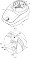
- the user can input an unlocking instruction at the instruction input area, and the drive assembly 5 will drive the first locking member 4 to move to the unlocked position as shown in FIG. 11 .
- the abutting portion 41 is located outside the groove 141.
- the container assembly 2 can be removed from the body 1 conveniently.
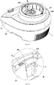
- the drive assembly 5 drives the first locking member 4 to move to the locked position shown in FIG. 12 .
- the abutting portion 41 slides into the groove 141 to cooperate with the limiting portion 241, and thus the container assembly 2 is locked on the body 1.
- the detection mechanism can also detect the position of the first locking member 4 so as to control the start and stop of the drive assembly 5, so that the first locking member 4 moves to the unlocked position or the locked position accurately.
- the detection mechanism further includes a first sensing member 75, a first bracket 76 and a third sensing member 77.
- the first sensing member 75 is mounted on the first bracket 76
- the third sensing member 77 is mounted on the mounting frame 51.
- the drive assembly 5 drives the first locking member 4 to move.
- the first locking member 4 moves to the locked position, as shown in FIG. 12
- the first locking member 4 can trigger the first sensing member 75, and then the drive assembly 5 is controlled to stop, so as to stabilize the first locking member 4 at the locked position.
- the drive assembly 5 drives the first locking member 4 to move to the unlocked position, so that the first locking member 4 can trigger the third sensing member 77, and then the drive assembly 5 is controlled to stop, so as to stabilize the first locking member 4 at the unlocked position.
- the first sensing member 75, the second sensing member 72, and the third sensing member 77 may all be micro switches, which are triggered by pressing a spring sheet of the micro switch.
- first sensing member 75, the second sensing member 72, and the third sensing member 77 may also be other types such as contact sensors or proximity sensors to implement the above functions.
- control system of the food preparation device may be electrically connected to the detection mechanism.
- the micro switch obtains the position information of the first locking member 4 and the mounting state of the container assembly 2 on the body 1, and transmits this information to the control system.
- the control system controls the drive assembly 5 to start or stop according to the received information.
- This embodiment provides a food preparation device.
- the difference of the food preparation device in embodiment 2 from that in embodiment 1 is that the detection mechanism can detect whether the cover 21 and the container 22 are closed in place or not, so as to avoid the cover 21 or the food materials in the container 22 from being thrown out due to the screwing-loosening of the cover 21 when the food preparation device is operating, and thus the safety performance of the food preparation device is improved.
- the triggering member 26 can trigger the second sensing member 72 in the body 1; otherwise, the triggering member 26 cannot trigger the second sensing member 72.
- the sensor 72 determines whether the cover 21 and the container 22 are closed in place.
- the triggering member 26 When the cover 21 and the container 22 are closed in place, the triggering member 26 extends beyond the handle 23 to a longer length, and the triggering member 26 can trigger the second sensing member 72 on the body 1 to generate the information that the cover 21 has been mounted on the container 22 in place. As shown in FIG. 13 , when the cover 21 and the container 22 are not closed in place, the triggering member 26 extends beyond the handle 23 to a short length, and the triggering member 26 cannot trigger the second sensing member 72 on the body 1, such that the cover 21 is determined to be abnormally covered on the container 22.
- the triggering member 26 is provided inside the handle 23, and the handle 23 is provided with a notch 231.
- the cover 21 is provided with a first inclined surface 211, and the triggering member 26 is resetably arranged on the container 22.
- the triggering member 26 is provided with a second inclined surface 261.
- the cover 21 covers the container 22 in a rotating manner.
- the first inclined surface 211 on the cover 21 can be slidably matched with the second inclined surface 261 on the triggering member 26 through the notch 231, so as to drive the triggering member 26 to move.
- the triggering member 26 is retracted into the handle 23 under the action of the second reset member 27.
- the first inclined surface 211 on the cover 21 can be slidably matched with the second inclined surface 261 on the triggering member 26 and push the triggering member 26 to slide downwards, so that the lower end of the triggering member 26 gradually extends out of the handle 23 so as to abut against the adapter 71.
- a food preparation device is provided.
- the difference of the food preparation device in embodiment 3 from those in the above embodiments is that when the container assembly 2 is locked with the body 1 together, the cover 21 can be locked with the main body together, which improves the safety performance of the food preparation device.
- the container assembly 2 is provided with a second locking member 61 which is movable.
- the first locking member 4 can drive the second locking member 61 to move, so as to lock the cover 21 on the main body.
- the second locking member 61 can also be arranged in the handle 23.
- the second locking member 61 is slidably connected with the container 22 in the vertical direction and has a reset function.
- the first locking member 4 is moved to the unlocked position, the second locking member 61 will automatically be reset and the locking of the cover 21 and the container 22 is released, so that the container assembly 2 can be opened.
- the second locking member 61 and the container 22 are connected by a third reset member 62.
- the third reset member 62 may be a spring.
- the first locking member 4 can drive the second locking member 61 to move upwards so as to lock the cover 21.
- the first locking member 4 is provided with a third inclined surface 42 which can slidably cooperate the lower end of the second locking member 61.
- the third inclined surface 42 gradually slides into the groove 141 and cooperates with the lower end of the second locking member 61 extending into the groove 141.
- the third inclined surface 42 gradually decreases in height along the direction of sliding into the groove 141, so that the second locking member 61 slides upwards when sliding along the third inclined surface 42, so that the second locking member 61 achieves the locking of the cover 21.
- a block 212 is provided at the bottom of the cover 21.
- the top end of the second locking member 61 abuts against a side of the block 212 facing away from the screwing-tightening direction of the cover 21, so that the cover 21 is prevented from rotating in the screwing-loosening direction relative to the container 22, and the purpose of locking the cover 21 is achieved.
- the second locking member 61 slides down and no longer abuts against the block 212, and the locking of cover 21 and the container 22 is released.
Landscapes
- Engineering & Computer Science (AREA)
- Food Science & Technology (AREA)
- Mechanical Engineering (AREA)
- Food-Manufacturing Devices (AREA)
- Cookers (AREA)
Applications Claiming Priority (2)
| Application Number | Priority Date | Filing Date | Title |
|---|---|---|---|
| CN201910785229.3A CN110448201B (zh) | 2019-08-23 | 2019-08-23 | 一种料理机 |
| PCT/CN2019/114113 WO2021035929A1 (fr) | 2019-08-23 | 2019-10-29 | Robot de cuisine |
Publications (2)
| Publication Number | Publication Date |
|---|---|
| EP3821773A1 true EP3821773A1 (fr) | 2021-05-19 |
| EP3821773A4 EP3821773A4 (fr) | 2021-11-10 |
Family
ID=68488773
Family Applications (1)
| Application Number | Title | Priority Date | Filing Date |
|---|---|---|---|
| EP19940167.0A Pending EP3821773A4 (fr) | 2019-08-23 | 2019-10-29 | Robot de cuisine |
Country Status (3)
| Country | Link |
|---|---|
| EP (1) | EP3821773A4 (fr) |
| CN (1) | CN110448201B (fr) |
| WO (1) | WO2021035929A1 (fr) |
Cited By (2)
| Publication number | Priority date | Publication date | Assignee | Title |
|---|---|---|---|---|
| WO2023281150A1 (fr) * | 2021-07-09 | 2023-01-12 | Cecotec Research and Development S.L. | Dispositif de verrouillage électromécanique pour robot de cuisine |
| EP4649867A1 (fr) * | 2024-01-23 | 2025-11-19 | Seb S.A. | Appareil électroménager de préparation d' aliments |
Families Citing this family (5)
| Publication number | Priority date | Publication date | Assignee | Title |
|---|---|---|---|---|
| CN114668320B (zh) * | 2020-12-24 | 2024-03-12 | 莱克电气绿能科技(苏州)有限公司 | 一种料理机 |
| CN112754261B (zh) * | 2021-02-02 | 2025-03-11 | 佛山市顺德区富升电子科技有限公司 | 料理机 |
| CN114305168B (zh) * | 2021-12-02 | 2023-12-12 | 广东纯米电器科技有限公司 | 食物料理机 |
| CN114534879A (zh) * | 2022-02-22 | 2022-05-27 | 广东力然电器实业有限公司 | 一种自动锁紧绞肉接头的绞肉机 |
| CN116869425A (zh) * | 2023-04-28 | 2023-10-13 | 深圳银星智能集团股份有限公司 | 清洁基站及清洁系统 |
Family Cites Families (12)
| Publication number | Priority date | Publication date | Assignee | Title |
|---|---|---|---|---|
| JP4526155B2 (ja) * | 2000-04-24 | 2010-08-18 | 株式会社ニッセー | 多機能抽出器 |
| CN1465322A (zh) * | 2002-07-04 | 2004-01-07 | 乐金电子(天津)电器有限公司 | 压力电饭锅错误开启防止装置 |
| CN201139425Y (zh) * | 2008-01-18 | 2008-10-29 | 佛山市顺德区爱德实业有限公司 | 一种可自动锁定的电压力锅 |
| DE102011000219A1 (de) * | 2010-03-31 | 2011-10-06 | Vorwerk & Co. Interholding Gmbh | Elektromotorisch betriebene Küchenmaschine, sowie Zubereitungsgefäß |
| CH704759A1 (de) * | 2011-03-29 | 2012-10-15 | Pi Design Ag | Behälterverschluss. |
| DE102014112267A1 (de) * | 2014-08-27 | 2016-03-03 | Vorwerk & Co. Interholding Gmbh | Küchenmaschine mit Verriegelungseinrichtung |
| CN105662127B (zh) * | 2014-12-08 | 2018-01-02 | (株)酷晨 | 电压力饭锅、自动锁定装置、自动压力锁定功能控制方法 |
| CN205041278U (zh) * | 2015-09-30 | 2016-02-24 | 浙江绍兴苏泊尔生活电器有限公司 | 搅拌杯及具有其的料理机 |
| CN105996827A (zh) * | 2016-07-23 | 2016-10-12 | 中山市伊丝顿电器有限公司 | 一种破壁料理机 |
| CN108201340B (zh) * | 2016-12-20 | 2020-09-15 | 佛山市顺德区美的电热电器制造有限公司 | 盖开闭机构和烹饪厨具 |
| CN109984588B (zh) * | 2018-01-03 | 2021-12-17 | 佛山市顺德区美的电热电器制造有限公司 | 烹饪器具及其上盖组件 |
| CN108567304B (zh) * | 2018-06-15 | 2023-07-21 | 莱克电气股份有限公司 | 一种食品处理装置 |
-
2019
- 2019-08-23 CN CN201910785229.3A patent/CN110448201B/zh active Active
- 2019-10-29 EP EP19940167.0A patent/EP3821773A4/fr active Pending
- 2019-10-29 WO PCT/CN2019/114113 patent/WO2021035929A1/fr not_active Ceased
Cited By (3)
| Publication number | Priority date | Publication date | Assignee | Title |
|---|---|---|---|---|
| WO2023281150A1 (fr) * | 2021-07-09 | 2023-01-12 | Cecotec Research and Development S.L. | Dispositif de verrouillage électromécanique pour robot de cuisine |
| ES2932444A1 (es) * | 2021-07-09 | 2023-01-19 | Cecotec Res And Development S L | Dispositivo de enclavamiento electromecanico para robot de cocina |
| EP4649867A1 (fr) * | 2024-01-23 | 2025-11-19 | Seb S.A. | Appareil électroménager de préparation d' aliments |
Also Published As
| Publication number | Publication date |
|---|---|
| EP3821773A4 (fr) | 2021-11-10 |
| CN110448201B (zh) | 2021-07-09 |
| WO2021035929A1 (fr) | 2021-03-04 |
| CN110448201A (zh) | 2019-11-15 |
Similar Documents
| Publication | Publication Date | Title |
|---|---|---|
| EP3821773A1 (fr) | Robot de cuisine | |
| EP3821774B1 (fr) | Robot de cuisine | |
| US9433324B2 (en) | Kitchen appliance for processing foodstuff and method of operating same | |
| EP2005867A1 (fr) | Appareil de cuisine, stabilisateur et ensemble de bras | |
| CN102647931B (zh) | 包括具有电阻的工作容器的烹饪制备家电设备 | |
| US3635270A (en) | Combination can opener and slicing shredding appliance | |
| JP4015967B2 (ja) | 食材調製器 | |
| CN210748879U (zh) | 一种料理机 | |
| JP2017520333A (ja) | 食品加工用調理器具 | |
| CN211459909U (zh) | 一种料理机 | |
| CN117356945A (zh) | 一种具有榨汁功能的多功能食物处理机 | |
| JP2001309859A (ja) | 電動調理器 | |
| CN111603073B (zh) | 杯盖组件、搅拌杯组件及料理机 | |
| CN208822548U (zh) | 杯体组件及料理机 | |
| CN211243022U (zh) | 一种加工效率高的便携式食品加工机 | |
| CN219374453U (zh) | 食品加工机 | |
| CN222323311U (zh) | 烹饪器具 | |
| CN221083485U (zh) | 一种便于榨汁的多功能食物处理机 | |
| CN223554642U (zh) | 一种提高使用安全性的果汁机 | |
| KR200485526Y1 (ko) | 자성체를 이용하여 동작이 제어되는 요리 기기 | |
| JPS5849736Y2 (ja) | 食品調理器の保護装置 | |
| CN221616770U (zh) | 烹饪器具 | |
| JPS6115537B2 (fr) | ||
| CN216776785U (zh) | 一种烹饪料理机的锅盖锁紧机构 | |
| CN219249932U (zh) | 多功能料理设备 |
Legal Events
| Date | Code | Title | Description |
|---|---|---|---|
| STAA | Information on the status of an ep patent application or granted ep patent |
Free format text: STATUS: UNKNOWN |
|
| STAA | Information on the status of an ep patent application or granted ep patent |
Free format text: STATUS: THE INTERNATIONAL PUBLICATION HAS BEEN MADE |
|
| PUAI | Public reference made under article 153(3) epc to a published international application that has entered the european phase |
Free format text: ORIGINAL CODE: 0009012 |
|
| STAA | Information on the status of an ep patent application or granted ep patent |
Free format text: STATUS: REQUEST FOR EXAMINATION WAS MADE |
|
| 17P | Request for examination filed |
Effective date: 20210209 |
|
| AK | Designated contracting states |
Kind code of ref document: A1 Designated state(s): AL AT BE BG CH CY CZ DE DK EE ES FI FR GB GR HR HU IE IS IT LI LT LU LV MC MK MT NL NO PL PT RO RS SE SI SK SM TR |
|
| A4 | Supplementary search report drawn up and despatched |
Effective date: 20211013 |
|
| RIC1 | Information provided on ipc code assigned before grant |
Ipc: A47J 27/04 20060101ALI20211006BHEP Ipc: A47J 19/02 20060101ALI20211006BHEP Ipc: A47J 43/07 20060101ALI20211006BHEP Ipc: A47J 43/046 20060101AFI20211006BHEP |
|
| DAV | Request for validation of the european patent (deleted) | ||
| DAX | Request for extension of the european patent (deleted) | ||
| STAA | Information on the status of an ep patent application or granted ep patent |
Free format text: STATUS: EXAMINATION IS IN PROGRESS |
|
| 17Q | First examination report despatched |
Effective date: 20231004 |
|
| GRAP | Despatch of communication of intention to grant a patent |
Free format text: ORIGINAL CODE: EPIDOSNIGR1 |
|
| STAA | Information on the status of an ep patent application or granted ep patent |
Free format text: STATUS: GRANT OF PATENT IS INTENDED |
|
| INTG | Intention to grant announced |
Effective date: 20251215 |
|
| GRAS | Grant fee paid |
Free format text: ORIGINAL CODE: EPIDOSNIGR3 |
|
| GRAA | (expected) grant |
Free format text: ORIGINAL CODE: 0009210 |
|
| STAA | Information on the status of an ep patent application or granted ep patent |
Free format text: STATUS: THE PATENT HAS BEEN GRANTED |