EP3821932A1 - Verbindungselement zum verbinden eines schlauchstutzenteils - Google Patents
Verbindungselement zum verbinden eines schlauchstutzenteils Download PDFInfo
- Publication number
- EP3821932A1 EP3821932A1 EP19220017.8A EP19220017A EP3821932A1 EP 3821932 A1 EP3821932 A1 EP 3821932A1 EP 19220017 A EP19220017 A EP 19220017A EP 3821932 A1 EP3821932 A1 EP 3821932A1
- Authority
- EP
- European Patent Office
- Prior art keywords
- gas valve
- valve system
- output portion
- hose barb
- gas
- Prior art date
- Legal status (The legal status is an assumption and is not a legal conclusion. Google has not performed a legal analysis and makes no representation as to the accuracy of the status listed.)
- Withdrawn
Links
- 230000001105 regulatory effect Effects 0.000 claims abstract description 12
- 238000011144 upstream manufacturing Methods 0.000 claims abstract description 11
- 230000001276 controlling effect Effects 0.000 claims abstract description 7
- 239000000463 material Substances 0.000 claims description 12
- 239000007787 solid Substances 0.000 claims description 6
- 241000191291 Abies alba Species 0.000 claims description 4
- 239000004033 plastic Substances 0.000 claims description 3
- 239000007789 gas Substances 0.000 description 86
- QVGXLLKOCUKJST-UHFFFAOYSA-N atomic oxygen Chemical compound [O] QVGXLLKOCUKJST-UHFFFAOYSA-N 0.000 description 5
- 238000000034 method Methods 0.000 description 5
- 239000001301 oxygen Substances 0.000 description 5
- 229910052760 oxygen Inorganic materials 0.000 description 5
- 239000004909 Moisturizer Substances 0.000 description 4
- 230000001333 moisturizer Effects 0.000 description 4
- 235000004507 Abies alba Nutrition 0.000 description 3
- 230000001419 dependent effect Effects 0.000 description 3
- 241001631457 Cannula Species 0.000 description 1
- 238000001035 drying Methods 0.000 description 1
- 210000004400 mucous membrane Anatomy 0.000 description 1
- 238000002640 oxygen therapy Methods 0.000 description 1
- 230000009467 reduction Effects 0.000 description 1
- 230000029058 respiratory gaseous exchange Effects 0.000 description 1
- 210000001519 tissue Anatomy 0.000 description 1
Images

Classifications
-
- A—HUMAN NECESSITIES
- A61—MEDICAL OR VETERINARY SCIENCE; HYGIENE
- A61M—DEVICES FOR INTRODUCING MEDIA INTO, OR ONTO, THE BODY; DEVICES FOR TRANSDUCING BODY MEDIA OR FOR TAKING MEDIA FROM THE BODY; DEVICES FOR PRODUCING OR ENDING SLEEP OR STUPOR
- A61M16/00—Devices for influencing the respiratory system of patients by gas treatment, e.g. ventilators; Tracheal tubes
- A61M16/20—Valves specially adapted to medical respiratory devices
-
- A—HUMAN NECESSITIES
- A61—MEDICAL OR VETERINARY SCIENCE; HYGIENE
- A61M—DEVICES FOR INTRODUCING MEDIA INTO, OR ONTO, THE BODY; DEVICES FOR TRANSDUCING BODY MEDIA OR FOR TAKING MEDIA FROM THE BODY; DEVICES FOR PRODUCING OR ENDING SLEEP OR STUPOR
- A61M16/00—Devices for influencing the respiratory system of patients by gas treatment, e.g. ventilators; Tracheal tubes
- A61M16/08—Bellows; Connecting tubes ; Water traps; Patient circuits
- A61M16/0816—Joints or connectors
-
- A—HUMAN NECESSITIES
- A61—MEDICAL OR VETERINARY SCIENCE; HYGIENE
- A61M—DEVICES FOR INTRODUCING MEDIA INTO, OR ONTO, THE BODY; DEVICES FOR TRANSDUCING BODY MEDIA OR FOR TAKING MEDIA FROM THE BODY; DEVICES FOR PRODUCING OR ENDING SLEEP OR STUPOR
- A61M16/00—Devices for influencing the respiratory system of patients by gas treatment, e.g. ventilators; Tracheal tubes
- A61M16/08—Bellows; Connecting tubes ; Water traps; Patient circuits
- A61M16/0875—Connecting tubes
-
- A—HUMAN NECESSITIES
- A61—MEDICAL OR VETERINARY SCIENCE; HYGIENE
- A61M—DEVICES FOR INTRODUCING MEDIA INTO, OR ONTO, THE BODY; DEVICES FOR TRANSDUCING BODY MEDIA OR FOR TAKING MEDIA FROM THE BODY; DEVICES FOR PRODUCING OR ENDING SLEEP OR STUPOR
- A61M16/00—Devices for influencing the respiratory system of patients by gas treatment, e.g. ventilators; Tracheal tubes
- A61M16/10—Preparation of respiratory gases or vapours
-
- A—HUMAN NECESSITIES
- A61—MEDICAL OR VETERINARY SCIENCE; HYGIENE
- A61M—DEVICES FOR INTRODUCING MEDIA INTO, OR ONTO, THE BODY; DEVICES FOR TRANSDUCING BODY MEDIA OR FOR TAKING MEDIA FROM THE BODY; DEVICES FOR PRODUCING OR ENDING SLEEP OR STUPOR
- A61M16/00—Devices for influencing the respiratory system of patients by gas treatment, e.g. ventilators; Tracheal tubes
- A61M16/20—Valves specially adapted to medical respiratory devices
- A61M16/201—Controlled valves
-
- A—HUMAN NECESSITIES
- A61—MEDICAL OR VETERINARY SCIENCE; HYGIENE
- A61M—DEVICES FOR INTRODUCING MEDIA INTO, OR ONTO, THE BODY; DEVICES FOR TRANSDUCING BODY MEDIA OR FOR TAKING MEDIA FROM THE BODY; DEVICES FOR PRODUCING OR ENDING SLEEP OR STUPOR
- A61M2202/00—Special media to be introduced, removed or treated
- A61M2202/0007—Special media to be introduced, removed or treated introduced into the body
-
- A—HUMAN NECESSITIES
- A61—MEDICAL OR VETERINARY SCIENCE; HYGIENE
- A61M—DEVICES FOR INTRODUCING MEDIA INTO, OR ONTO, THE BODY; DEVICES FOR TRANSDUCING BODY MEDIA OR FOR TAKING MEDIA FROM THE BODY; DEVICES FOR PRODUCING OR ENDING SLEEP OR STUPOR
- A61M2202/00—Special media to be introduced, removed or treated
- A61M2202/02—Gases
- A61M2202/0208—Oxygen
Definitions
- the invention relates to the medical field. More particularly, the present invention relates to systems and methods for administering gas to a patient, e.g. using a nasal cannula or breathing mask.
- gases in medical applications are widespread.
- One of the gases often administered to patients for medical reasons is oxygen.
- oxygen In view of the fact that administering oxygen is often essential for preventing damage to tissue, avoiding life-threatening situations or saving a patient from a life-threatening situation, hospitals distribute oxygen using a pipeline network up to the bed of nearly each patient.
- oxygen therapy is also widespread for homecare patients, making use of pressurised oxygen bottles and or oxygen concentrators.
- a gas valve system is used for controlling the flow, i.e. between 1 I/min and 15 I/min or higher, and the type of delivery, i.e. continuous flow or on demand flow.
- Gas valve systems exist both in full mechanical as well as in combined mechanical and electronic configurations.
- the gas valve system typically comprises a hose barb component.
- hose barb components are well known to the person skilled in the art. They typically are provided on one side with a threaded portion for connected, in a substantially gas tight manner, the hose barb component to the remaining part of the gas valve system and on the other side have a particular shape referred to as Christmas-tree shape, allowing to slide the tubing onto the hose barb component in an easy manner.
- This easy way of connecting tubing to the gas valve system allows avoiding the need for a clamping ring for mounting tubing to the gas valve system and hence prevents loss of time when mounting the tubing to the gas valve system.
- a moisturizer also referred to as humidifier
- the moisturizer typically is directly mounted on the gas valve using mutually matching threaded portions.
- the hose barb component used for connecting the tubing of the nasal cannula or mouth mask to the remaining part of the gas valve system, typically is not used.
- hose barb components typically get lost, when switching between medical gas administration using a moisturizer and medical gas administration without using a moisturizer. This leads to loss of time for the medical staff and to the need of additional hose barb components in order to replace the lost hose barb components.
- the present invention relates to a gas valve system adapted for controlling the flow of a medical gas for a user, the gas valve system comprising an input portion for connecting the gas valve to an external supply, a regulating system for regulating the flow of the gas and an output portion for providing the controlled flow of the medical gas towards the user, the output portion having a tubular shaped ending with a threaded portion for releasably connecting a hose barb component suitable for connecting tubing to the gas valve, characterised in that the output portion furthermore has a protrusion upstream the threaded portion, and the system having a linking element being connected to the output portion of the gas valve system upstream the protrusion and being suitable for fixedly linking the hose barb component to the output portion of the gas valve system.
- Embodiments of the present invention thus provide, when the hose barb component is mounted on the gas valve system a first releasable connection between the hose barb component and the gas valve via their threaded portions to provide gas flow from the gas valve through the hose barb component towards the user and a second fixed connection between the hose barb component and the gas valve system via the linking element for fixedly connecting the hose barb component to the gas valve, allowing for example to prevent loss of the hose barb component when the hose barb component is not in use, e.g. when a humidifier such as an aqua pack is connected to the gas valve.
- the hose barb is fixedly linked to the output portion so that, when the hose barb component is loosened from the threaded portion of the output portion, the hose barb component is still fixedly linked to the output portion and the hose barb component cannot be lost when it is not in use for connecting the gas valve system with tubing towards a user.
- the protrusion may be ring-shaped and is extending around the output portion. It is an advantage of a protrusion that is extending around the output portion, e.g. along the circumference of the tubular shaped portion of the output portion, that the linking element cannot slip off the output portion and that the hose barb component thus has a good fixed connection to the output portion.
- the linking element may comprise an opening with a diameter smaller than an outer diameter of the protrusion and the output portion may pass through the opening at the position upstream the protrusion of the output portion.
- the linking element may be a flexible element. It is an advantage of embodiments of the present invention that the linking element is a flexible element allowing a more easy releasing the releasable connection of the hose barb component at its threaded portion.
- the linking element may comprise a strip of solid flexible material. In some embodiments, the linking element may be made of a strip of solid flexible material. The strip of solid flexible material may be made of any of a plastic material or a rubber material.
- the linking element may comprise a chain.
- the hose barb component may be a part of the gas valve system.
- the hose barb component may have a threaded portion for obtaining said releasable connection to the output portion via the threaded portion of the tubular shaped ending of the output portion and the hose barb component furthermore may be connected to the linking element for providing said fixed connection between the hose barb component and the output portion of the gas valve system.
- the hose barb component comprises a portion with a Christmas tree shape.
- FIG. 1 to FIG. 5 illustrates gas valve systems according to embodiments of the present invention.
- the present invention relates to a gas valve system adapted for controlling the flow of a medical gas for a user.
- the gas valve system may be for use in hospital, for use at home or may be for mixed use.
- the gas valve system may be for continuous flow and/or may be for on demand use. It may be a gas valve system as described for example in international patent application WO2012/153293 , although embodiments are not limited thereto.
- the gas valve system may be based on only mechanical components or may be based on a combination of mechanical and electronical components.
- the gas valve system comprises an input portion for connecting the gas valve to an external supply.
- an external supply may for example be a pressurised gas bottle or may be a gas supply network as typically available in hospitals.
- the input portion may be as known from prior art and is therefore not further detailed here.
- the system also comprises a regulating system for regulating the flow of the medical gas.
- the present invention is not limited to the particular regulating system used. Such a system may for example be only mechanical or may comprise a combination of mechanical and electronic components.
- a regulating system is described in WO2012/153293 , although embodiments are not limited thereto.
- the gas valve system also comprises an output portion for providing the controlled flow of the medical gas towards the user.
- the medical gas may for example be administered to the user making use of a nasal cannula or a mouth mask.
- the output portion has a tubular shaped ending with a threaded portion for releasably connecting a hose barb component suitable for connecting tubing to the gas valve.
- the output portion furthermore has a protrusion upstream the threaded portion.
- the system further has a linking element being connected to the output portion of the gas valve system upstream the protrusion and being suitable for fixedly linking the hose barb component to the output portion of the gas valve system.
- the protrusion may be ring-shaped and extending around the output portion.
- the system thus typically may be configured such that the linking element is withheld from being removed from the remaining part of the gas valve system by the protrusion, e.g. withheld from being removed when no large force is applied to the linking element.
- a force is considered large if it is substantially higher than for example the gravitational force present when a hose barb component is connected to the linking element that is not attached to the gas valve system in another manner than through the linking element.
- Embodiments of the present invention provide, when the hose barb component is mounted on the gas valve system a first releasable connection between the hose barb component and the gas valve via their threaded portions to provide gas flow from the gas valve through the hose barb component towards the user and a second fixed connection between the hose barb component and the gas valve system via the linking element for fixedly connecting the hose barb component to the gas valve.
- the linking element may for example comprise an opening with a diameter smaller than an outer diameter of the protrusion and the output portion passes through the opening at the position upstream the protrusion of the output portion.
- the linking element may be a flexible element.
- the linking element comprises a strip of solid flexible material, for example strip of plastic material or a rubber material.
- part of the linking element also may comprise a chain.
- the hose barb component is part of the gas valve system.
- the hose barb component typically may comprise a threaded portion for obtaining the releasable connection to the output portion via the threaded portion of the tubular shaped ending of the output portion.
- the hose barb component also is connected to the linking element for providing said fixed link between the hose barb component and the output portion of the gas valve system. Such a connection may be performed in a variety of ways.
- the hose barb component may comprise a portion with a Christmas tree shape, as well known by the person skilled in the art. More generally, the hose barb component may have at one side a shape suitable for easily connecting tubing such as tubing of a nasal cannula or a mouth mask.
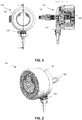
- FIG. 1 an example of an embodiment illustrating a gas valve system with a linking element is shown in FIG. 1 .
- the gas valve system 100 is shown with linking element 110, connecting the hose barb component 120 fixedly to the remaining part of the gas valve system.
- the remaining gas valve system also shows the input portion 120 and the gas regulating system 130.
- the gas valve system is show in front view (left hand side) and in cross-sectional view (right hand side).
- the detailed features of the internal part of the remaining part of the gas valve system are not limiting for the present invention, as also indicated above.
- the explicit configuration of the linking element such as the length, the way it is connected or connectable to the hose barb component, etc. is also not limiting.
- FIG. 2 a gas valve system is shown, in the present case with a hose barb component connected to the remaining part of the gas valve.
- FIG. 3 a gas valve system with a linking element is shown. The hose barb component is not being releasably connected through the threaded portions but only is fixedly connected through the linking element 110.
- the input portion 120 and the gas regulating system 130 is also shown.
- FIG. 4 illustrates a similar gas valve system whereby the hose barb component is releasably connected to the remaining part of the gas valve system.
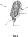
- FIG. 5 also shows a gas valve system according to an embodiment of the present invention.
- the present invention also relates to a linking element adapted for use in a gas valve system adapted for controlling the flow of a medical gas for a user, a gas valve system as described in the first aspect.
Landscapes
- Health & Medical Sciences (AREA)
- Emergency Medicine (AREA)
- Pulmonology (AREA)
- Engineering & Computer Science (AREA)
- Anesthesiology (AREA)
- Biomedical Technology (AREA)
- Heart & Thoracic Surgery (AREA)
- Hematology (AREA)
- Life Sciences & Earth Sciences (AREA)
- Animal Behavior & Ethology (AREA)
- General Health & Medical Sciences (AREA)
- Public Health (AREA)
- Veterinary Medicine (AREA)
- Infusion, Injection, And Reservoir Apparatuses (AREA)
Priority Applications (6)
| Application Number | Priority Date | Filing Date | Title |
|---|---|---|---|
| EP20797439.5A EP4048359A1 (de) | 2019-10-22 | 2020-10-22 | Gasventilsystem mit verteiler |
| PCT/EP2020/079837 WO2021078913A1 (en) | 2019-10-22 | 2020-10-22 | Vital parameter measurements for low care patients |
| EP20796801.7A EP4048147A1 (de) | 2019-10-22 | 2020-10-22 | Vitalparametermessungen für patienten mit geringer versorgung |
| US17/771,210 US20220361753A1 (en) | 2019-10-22 | 2020-10-22 | Vital parameter measurements for low care patients |
| PCT/EP2020/079838 WO2021078914A1 (en) | 2019-10-22 | 2020-10-22 | Gas valve system with manifold |
| US17/727,417 US20220241529A1 (en) | 2019-10-22 | 2022-04-22 | Gas valve system with manifold |
Applications Claiming Priority (1)
| Application Number | Priority Date | Filing Date | Title |
|---|---|---|---|
| EP19209612 | 2019-11-17 |
Publications (1)
| Publication Number | Publication Date |
|---|---|
| EP3821932A1 true EP3821932A1 (de) | 2021-05-19 |
Family
ID=68609902
Family Applications (1)
| Application Number | Title | Priority Date | Filing Date |
|---|---|---|---|
| EP19220017.8A Withdrawn EP3821932A1 (de) | 2019-10-22 | 2019-12-30 | Verbindungselement zum verbinden eines schlauchstutzenteils |
Country Status (1)
| Country | Link |
|---|---|
| EP (1) | EP3821932A1 (de) |
Citations (4)
| Publication number | Priority date | Publication date | Assignee | Title |
|---|---|---|---|---|
| DE3234789A1 (de) * | 1982-09-20 | 1984-05-10 | The Kendall Co., 02101 Boston, Mass. | Wiederverwendbare anschlussvorrichtung |
| WO2012153293A1 (en) | 2011-05-10 | 2012-11-15 | Oxypoint Bvba | Valve for controlling gas flow |
| EP3050589A1 (de) * | 2002-02-04 | 2016-08-03 | Fisher & Paykel Healthcare Limited | Gerät zur unterstützung der atmung |
| US20190269868A1 (en) * | 2018-03-02 | 2019-09-05 | Msafe, Inc. | Breathing Gas Delivery System |
-
2019
- 2019-12-30 EP EP19220017.8A patent/EP3821932A1/de not_active Withdrawn
Patent Citations (4)
| Publication number | Priority date | Publication date | Assignee | Title |
|---|---|---|---|---|
| DE3234789A1 (de) * | 1982-09-20 | 1984-05-10 | The Kendall Co., 02101 Boston, Mass. | Wiederverwendbare anschlussvorrichtung |
| EP3050589A1 (de) * | 2002-02-04 | 2016-08-03 | Fisher & Paykel Healthcare Limited | Gerät zur unterstützung der atmung |
| WO2012153293A1 (en) | 2011-05-10 | 2012-11-15 | Oxypoint Bvba | Valve for controlling gas flow |
| US20190269868A1 (en) * | 2018-03-02 | 2019-09-05 | Msafe, Inc. | Breathing Gas Delivery System |
Similar Documents
| Publication | Publication Date | Title |
|---|---|---|
| US5636630A (en) | Respiratory device and method therefor | |
| US20190201646A1 (en) | Respiratory assistance device and system and method | |
| US9744325B2 (en) | Portable patient interface system | |
| US8517022B2 (en) | Minimally invasive nasal cannula | |
| US5787879A (en) | Method of administering oxygen to a patient after general anesthesia using a particular adapter | |
| US5762063A (en) | Bag-valve-mask resuscitator attachment having syringe and nebulizer injection ports | |
| US12097327B2 (en) | Emergency respiratory support devices, systems, and methods | |
| US20210085902A1 (en) | Rescue breathing apparatus | |
| WO2003015844A3 (en) | Medical tubing securing device | |
| US20140166015A1 (en) | Dual mode medical oxygen delivery system | |
| US20130312760A1 (en) | Soft Touch Nose & Ear Pads | |
| US20170028155A1 (en) | Couplings, tracheostomy tubes and airway systems | |
| EP3821932A1 (de) | Verbindungselement zum verbinden eines schlauchstutzenteils | |
| EP2812058B1 (de) | Vorrichtung zur steuerung des sauerstoff- und/oder luftstroms an nasenkanülen | |
| CN110292695A (zh) | 多人用雾化供氧管路 | |
| CN201283150Y (zh) | 一种输氧管 | |
| CN210933308U (zh) | 多人用雾化供氧管路 | |
| US20140261438A1 (en) | Multi-positional connector for respiratory support systems | |
| US20170173285A1 (en) | Fire Safety Oxygen Mask | |
| US20060201512A1 (en) | Nasal cannula | |
| CN214970621U (zh) | 一种用于麻醉机的转换接口装置 | |
| CN205433846U (zh) | 一种乳头型环甲膜气管穿刺针连接器及其急救装置 | |
| EP3747492B1 (de) | Druckregulator für cuff an endotrachealtuben, atmungssystem, das einen solchen regulator umfasst, und behälter, der eine kammer mit variablem volumen für einen solchen regulator umfasst | |
| FI64895B (fi) | Bronkoskopi-bedoevningsanordning | |
| CN205460325U (zh) | 一种乳头型环甲膜气管穿刺针连接管及其呼吸装置 |
Legal Events
| Date | Code | Title | Description |
|---|---|---|---|
| PUAI | Public reference made under article 153(3) epc to a published international application that has entered the european phase |
Free format text: ORIGINAL CODE: 0009012 |
|
| STAA | Information on the status of an ep patent application or granted ep patent |
Free format text: STATUS: THE APPLICATION HAS BEEN PUBLISHED |
|
| AK | Designated contracting states |
Kind code of ref document: A1 Designated state(s): AL AT BE BG CH CY CZ DE DK EE ES FI FR GB GR HR HU IE IS IT LI LT LU LV MC MK MT NL NO PL PT RO RS SE SI SK SM TR |
|
| STAA | Information on the status of an ep patent application or granted ep patent |
Free format text: STATUS: THE APPLICATION IS DEEMED TO BE WITHDRAWN |
|
| 18D | Application deemed to be withdrawn |
Effective date: 20211120 |