EP3821933A1 - Système de valve de gaz avec capteur de flux - Google Patents
Système de valve de gaz avec capteur de flux Download PDFInfo
- Publication number
- EP3821933A1 EP3821933A1 EP19220019.4A EP19220019A EP3821933A1 EP 3821933 A1 EP3821933 A1 EP 3821933A1 EP 19220019 A EP19220019 A EP 19220019A EP 3821933 A1 EP3821933 A1 EP 3821933A1
- Authority
- EP
- European Patent Office
- Prior art keywords
- gas
- channel
- manifold
- valve system
- gas valve
- Prior art date
- Legal status (The legal status is an assumption and is not a legal conclusion. Google has not performed a legal analysis and makes no representation as to the accuracy of the status listed.)
- Withdrawn
Links
- 230000009467 reduction Effects 0.000 claims description 50
- 238000005259 measurement Methods 0.000 claims description 3
- 239000002184 metal Substances 0.000 claims description 3
- 239000007789 gas Substances 0.000 description 136
- 239000000463 material Substances 0.000 description 8
- 238000000034 method Methods 0.000 description 7
- QVGXLLKOCUKJST-UHFFFAOYSA-N atomic oxygen Chemical compound [O] QVGXLLKOCUKJST-UHFFFAOYSA-N 0.000 description 5
- 239000001301 oxygen Substances 0.000 description 5
- 229910052760 oxygen Inorganic materials 0.000 description 5
- 238000002560 therapeutic procedure Methods 0.000 description 4
- 230000001419 dependent effect Effects 0.000 description 3
- 238000009826 distribution Methods 0.000 description 3
- 238000004519 manufacturing process Methods 0.000 description 3
- 238000010146 3D printing Methods 0.000 description 2
- 238000000465 moulding Methods 0.000 description 2
- 238000009530 blood pressure measurement Methods 0.000 description 1
- 238000005266 casting Methods 0.000 description 1
- 230000008878 coupling Effects 0.000 description 1
- 238000010168 coupling process Methods 0.000 description 1
- 238000005859 coupling reaction Methods 0.000 description 1
- 238000002640 oxygen therapy Methods 0.000 description 1
- 238000003825 pressing Methods 0.000 description 1
- 230000000007 visual effect Effects 0.000 description 1
Images



Classifications
-
- A—HUMAN NECESSITIES
- A61—MEDICAL OR VETERINARY SCIENCE; HYGIENE
- A61M—DEVICES FOR INTRODUCING MEDIA INTO, OR ONTO, THE BODY; DEVICES FOR TRANSDUCING BODY MEDIA OR FOR TAKING MEDIA FROM THE BODY; DEVICES FOR PRODUCING OR ENDING SLEEP OR STUPOR
- A61M16/00—Devices for influencing the respiratory system of patients by gas treatment, e.g. ventilators; Tracheal tubes
- A61M16/20—Valves specially adapted to medical respiratory devices
-
- A—HUMAN NECESSITIES
- A61—MEDICAL OR VETERINARY SCIENCE; HYGIENE
- A61M—DEVICES FOR INTRODUCING MEDIA INTO, OR ONTO, THE BODY; DEVICES FOR TRANSDUCING BODY MEDIA OR FOR TAKING MEDIA FROM THE BODY; DEVICES FOR PRODUCING OR ENDING SLEEP OR STUPOR
- A61M16/00—Devices for influencing the respiratory system of patients by gas treatment, e.g. ventilators; Tracheal tubes
- A61M16/08—Bellows; Connecting tubes ; Water traps; Patient circuits
- A61M16/0816—Joints or connectors
-
- A—HUMAN NECESSITIES
- A61—MEDICAL OR VETERINARY SCIENCE; HYGIENE
- A61M—DEVICES FOR INTRODUCING MEDIA INTO, OR ONTO, THE BODY; DEVICES FOR TRANSDUCING BODY MEDIA OR FOR TAKING MEDIA FROM THE BODY; DEVICES FOR PRODUCING OR ENDING SLEEP OR STUPOR
- A61M16/00—Devices for influencing the respiratory system of patients by gas treatment, e.g. ventilators; Tracheal tubes
- A61M16/20—Valves specially adapted to medical respiratory devices
- A61M16/201—Controlled valves
- A61M16/202—Controlled valves electrically actuated
-
- A—HUMAN NECESSITIES
- A61—MEDICAL OR VETERINARY SCIENCE; HYGIENE
- A61M—DEVICES FOR INTRODUCING MEDIA INTO, OR ONTO, THE BODY; DEVICES FOR TRANSDUCING BODY MEDIA OR FOR TAKING MEDIA FROM THE BODY; DEVICES FOR PRODUCING OR ENDING SLEEP OR STUPOR
- A61M16/00—Devices for influencing the respiratory system of patients by gas treatment, e.g. ventilators; Tracheal tubes
- A61M16/0003—Accessories therefor, e.g. sensors, vibrators, negative pressure
- A61M2016/0027—Accessories therefor, e.g. sensors, vibrators, negative pressure pressure meter
-
- A—HUMAN NECESSITIES
- A61—MEDICAL OR VETERINARY SCIENCE; HYGIENE
- A61M—DEVICES FOR INTRODUCING MEDIA INTO, OR ONTO, THE BODY; DEVICES FOR TRANSDUCING BODY MEDIA OR FOR TAKING MEDIA FROM THE BODY; DEVICES FOR PRODUCING OR ENDING SLEEP OR STUPOR
- A61M16/00—Devices for influencing the respiratory system of patients by gas treatment, e.g. ventilators; Tracheal tubes
- A61M16/0003—Accessories therefor, e.g. sensors, vibrators, negative pressure
- A61M2016/003—Accessories therefor, e.g. sensors, vibrators, negative pressure with a flowmeter
-
- A—HUMAN NECESSITIES
- A61—MEDICAL OR VETERINARY SCIENCE; HYGIENE
- A61M—DEVICES FOR INTRODUCING MEDIA INTO, OR ONTO, THE BODY; DEVICES FOR TRANSDUCING BODY MEDIA OR FOR TAKING MEDIA FROM THE BODY; DEVICES FOR PRODUCING OR ENDING SLEEP OR STUPOR
- A61M2202/00—Special media to be introduced, removed or treated
- A61M2202/02—Gases
- A61M2202/0208—Oxygen
-
- A—HUMAN NECESSITIES
- A61—MEDICAL OR VETERINARY SCIENCE; HYGIENE
- A61M—DEVICES FOR INTRODUCING MEDIA INTO, OR ONTO, THE BODY; DEVICES FOR TRANSDUCING BODY MEDIA OR FOR TAKING MEDIA FROM THE BODY; DEVICES FOR PRODUCING OR ENDING SLEEP OR STUPOR
- A61M2205/00—General characteristics of the apparatus
- A61M2205/02—General characteristics of the apparatus characterised by a particular materials
- A61M2205/0272—Electro-active or magneto-active materials
- A61M2205/0294—Piezoelectric materials
-
- A—HUMAN NECESSITIES
- A61—MEDICAL OR VETERINARY SCIENCE; HYGIENE
- A61M—DEVICES FOR INTRODUCING MEDIA INTO, OR ONTO, THE BODY; DEVICES FOR TRANSDUCING BODY MEDIA OR FOR TAKING MEDIA FROM THE BODY; DEVICES FOR PRODUCING OR ENDING SLEEP OR STUPOR
- A61M2205/00—General characteristics of the apparatus
- A61M2205/33—Controlling, regulating or measuring
- A61M2205/3331—Pressure; Flow
- A61M2205/3334—Measuring or controlling the flow rate
-
- A—HUMAN NECESSITIES
- A61—MEDICAL OR VETERINARY SCIENCE; HYGIENE
- A61M—DEVICES FOR INTRODUCING MEDIA INTO, OR ONTO, THE BODY; DEVICES FOR TRANSDUCING BODY MEDIA OR FOR TAKING MEDIA FROM THE BODY; DEVICES FOR PRODUCING OR ENDING SLEEP OR STUPOR
- A61M2205/00—General characteristics of the apparatus
- A61M2205/50—General characteristics of the apparatus with microprocessors or computers
- A61M2205/502—User interfaces, e.g. screens or keyboards
-
- A—HUMAN NECESSITIES
- A61—MEDICAL OR VETERINARY SCIENCE; HYGIENE
- A61M—DEVICES FOR INTRODUCING MEDIA INTO, OR ONTO, THE BODY; DEVICES FOR TRANSDUCING BODY MEDIA OR FOR TAKING MEDIA FROM THE BODY; DEVICES FOR PRODUCING OR ENDING SLEEP OR STUPOR
- A61M2205/00—General characteristics of the apparatus
- A61M2205/58—Means for facilitating use, e.g. by people with impaired vision
- A61M2205/581—Means for facilitating use, e.g. by people with impaired vision by audible feedback
-
- A—HUMAN NECESSITIES
- A61—MEDICAL OR VETERINARY SCIENCE; HYGIENE
- A61M—DEVICES FOR INTRODUCING MEDIA INTO, OR ONTO, THE BODY; DEVICES FOR TRANSDUCING BODY MEDIA OR FOR TAKING MEDIA FROM THE BODY; DEVICES FOR PRODUCING OR ENDING SLEEP OR STUPOR
- A61M2205/00—General characteristics of the apparatus
- A61M2205/58—Means for facilitating use, e.g. by people with impaired vision
- A61M2205/583—Means for facilitating use, e.g. by people with impaired vision by visual feedback
-
- A—HUMAN NECESSITIES
- A61—MEDICAL OR VETERINARY SCIENCE; HYGIENE
- A61M—DEVICES FOR INTRODUCING MEDIA INTO, OR ONTO, THE BODY; DEVICES FOR TRANSDUCING BODY MEDIA OR FOR TAKING MEDIA FROM THE BODY; DEVICES FOR PRODUCING OR ENDING SLEEP OR STUPOR
- A61M2205/00—General characteristics of the apparatus
- A61M2205/60—General characteristics of the apparatus with identification means
- A61M2205/6045—General characteristics of the apparatus with identification means having complementary physical shapes for indexing or registration purposes
-
- A—HUMAN NECESSITIES
- A61—MEDICAL OR VETERINARY SCIENCE; HYGIENE
- A61M—DEVICES FOR INTRODUCING MEDIA INTO, OR ONTO, THE BODY; DEVICES FOR TRANSDUCING BODY MEDIA OR FOR TAKING MEDIA FROM THE BODY; DEVICES FOR PRODUCING OR ENDING SLEEP OR STUPOR
- A61M2205/00—General characteristics of the apparatus
- A61M2205/82—Internal energy supply devices
- A61M2205/8206—Internal energy supply devices battery-operated
-
- A—HUMAN NECESSITIES
- A61—MEDICAL OR VETERINARY SCIENCE; HYGIENE
- A61M—DEVICES FOR INTRODUCING MEDIA INTO, OR ONTO, THE BODY; DEVICES FOR TRANSDUCING BODY MEDIA OR FOR TAKING MEDIA FROM THE BODY; DEVICES FOR PRODUCING OR ENDING SLEEP OR STUPOR
- A61M2207/00—Methods of manufacture, assembly or production
Definitions
- the invention relates to the medical field. More particularly, the present invention relates to systems and methods for administering medical gas to a patient.
- gases in medical applications are widespread.
- One of the gasses often administered to patients for medical reasons is oxygen.
- oxygen In view of the fact that administering oxygen is often essential for preventing damage to tissue, avoiding life-threatening situations or saving a patient from a life-threatening situation, hospitals distribute oxygen using a pipeline network up to the bed of nearly each patient.
- oxygen therapy is also widespread for homecare patients, making use of pressurised oxygen bottles and or oxygen concentrators.
- a gas valve system is used for controlling the flow, i.e. between 1 I/min and 15 I/min or higher, and the type of delivery, i.e. continuous flow or on demand flow.
- a plurality of gas valve systems is available on the market, both in full mechanical as well as in combined mechanical and electronic configurations.
- the present invention relates to a gas valve system adapted for controlling the flow of a medical gas for a user, the gas valve system comprising a housing, one or more sensors, one or more electronic and/or mechanical components for controlling the gas flow, and a manifold comprising one or more channels for guiding the medical gas between an input and an output of the gas valve system and to which the one or more sensors and one or more electronic and/or mechanical components can be coupled.
- the channels may have an average diameter of between 0.1mm and 10mm, for example between 1mm and 5mm.
- One or more of the channels in the manifold may comprise one or more local channel diameter reductions, also referred to as orifice ring. It is an advantage of embodiments of the present invention that there is no need for a separate raster component which typically needs to be introduced in the gas tubing for allowing accurate operation of the gas valve system.
- the local channel diameter reduction also referred to as orifice ring, may be provided by local protrusions of the channel wall into the channel. It is an advantage of embodiments of the present invention that local channel diameter reductions can be easily introduced during the production process of the manifold.
- the channel may comprise openings in the channel wall before and after the local channel diameter reduction, to which a flow sensor can be coupled for measuring the flow of the medical gas in a bypass channel. It is an advantage of embodiments according to the present invention that by providing local channel diameter reductions, the system can be used with a smaller sensor for measuring the flow and/or smaller electronic and/or mechanical components.
- the openings in the channel wall may have an axial direction perpendicular to the overall longitudinal direction of the gas channel.
- the openings in the channel wall may have an axial direction non-perpendicular to the overall longitudinal direction of the gas channel.
- the manifold may be made of a single piece comprising the channels.
- the manifold may be made in any suitable manner, such as for example by moulding, by 3D printing, by processing a block of material, etc.
- the manifold may be made of any suitable material, such as for example it may for example be made of a plastic or a metal.
- the manifold may comprise alignment features for aligning one of the one or more sensors and/or one or more electronic or mechanical components with respect to the channels in the manifold. It is an advantage of embodiments of the present invention that easy positioning of the different components can be obtained during assembly of the gas valve system.
- the present invention also relates to a manifold for use in a gas valve system, the manifold comprising one or more channels for guiding a medical gas between an input and an output of the gas valve system and to which the one or more sensors and one or more electronic and/or mechanical components can be coupled .
- the one or more channels in the manifold may comprise one or more local channel diameter reductions, also referred to as orifice ring.
- the local channel diameter reduction may be provided by local protrusions of the channel wall into the channel.
- the channel may comprise openings in the channel wall before and after the local channel diameter reduction, to which a flow sensor can be coupled for measuring the flow of the medical gas in a bypass channel.
- the openings in the channel wall may have an axial direction perpendicular to the overall longitudinal direction of the gas channel or wherein the openings in the channel wall have an axial direction non-perpendicular to the overall longitudinal direction of the gas channel.
- the present invention also relates to a flow sensor for measurement of a gas flow, the flow sensor comprising one or more channels for guiding the gas between an input and an output of the one or more channels, wherein the one or more channels comprise one or more local channel diameter reductions and wherein the channel comprises openings in the channel wall before and after the local channel diameter reduction, to which a flow sensor can be coupled for measuring the flow of the medical gas in a bypass channel.
- the present invention relates to a gas valve system adapted for controlling the flow of a medical gas for a user.
- the gas valve system may be a gas valve system for delivering continuous gas flow to a patient, for administering gas flow on demand, or for allowing both continuous gas administering or on demand gas administering.
- the gas valve system is not limited to a system for a particular type of gas. Depending on the properties of the gas to be delivered, the different settings of the components may be adapted.
- the gas valve system comprises a housing. Such a housing may be made in any suitable material and may be of any suitable shape. In the housing, one ore more sensors such as for example an absolute pressure sensor, a flow sensor, a differential pressure sensor, etc.
- the gas valve system also comprises one or more electronic or mechanical components, such as for example valves like needle valves, for controlling the amount of gas flow that is to be administered.
- the gas valve system also may comprise an electronic or mechanical input means for allowing a user to provide the required input.
- the gas valve system also comprises a manifold comprising one or more channels for guiding the medical gas between an input and an output of the gas valve system and to which the one or more sensors and one or more electronic and/or mechanical components can be coupled.
- the channels in the manifold may be fixed channels formed in the material of the manifold.
- the channels may have a diameter between 0.1mm and 10mm, e.g. between 0.5mm and 5mm.
- the cross-sectional shape of the channels may depend on the manufacturing technique of the manifold.
- the channels may have a square cross section, a rectangular cross section, a circular cross-section etc.
- the manifold may be made of a single piece comprising the channels, but also may comprise of a plurality of pieces.
- two major parts of the manifold may be present, whereby the two parts fit together and can be mounted to form a single piece.
- the manifold also could be made of a single piece.
- the manifold may be made in a plurality of manners, such as for example using moulding, using casting, using processing of a block of material, using 3D printing, and alike.
- the manifold may be made of any suitable material such as for example made of plastic, of metal, etc.
- the manifold also may comprise alignment features for aligning one of the one or more sensors and/or one or more electronic or mechanical components with respect to the channels in the manifold.
- the gas valve system also may comprise an output means for displaying information regarding the gas delivery.
- the displaying means may be a display for graphically or numerically displaying information.
- the displaying means may be a visual indication, such as for example a LED ring.
- the gas valve system may comprise one or more channels in the manifold having one or more local channel diameter reductions, e.g. for obtaining flow reductions or measuring a flow.
- a local channel diameter reduction may overcome the need for using a honeycomb material in the channel, as typically is required in conventional systems for creating a differential pressure measurement system.
- the local channel diameter reduction may be provided by local protrusions of the channel wall into the channel.
- the channel may comprise openings in the channel wall before and after the local channel diameter reduction, to which a flow sensor can be coupled for measuring the flow of the medical gas in a bypass channel.
- the opening in the channel wall may have an axial direction perpendicular to the overall longitudinal direction of the gas channel or they may have an axial direction non-perpendicular to the overall longitudinal direction of the gas channel.
- the angle with respect to the overall longitudinal direction of the gas channel may be such that the amount of disturbance of the gas flow in the main channel is limited.
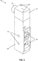
- FIG. 1 shows an elevated view of the manifold 200.
- the manifold 200 is built from two parts 202, 204, which allows for an easy assembly of the pressure reduction component that is present in the manifold and that will be discussed later.
- FIG. 1 furthermore the positions 206 where the different sensors will be positioned can be seen. It is an advantage of embodiments of the present invention that the predefined upstanding edges and shaped features allow for an accurate positioning of the different sensors.
- FIG. 1 also illustrates a manifold input part 212 that is adapted for introducing the gas into the manifold.
- the manifold input part 212 may comprise in one example a threaded part for connecting a standard input connector to it.
- a standard input connector may be a DIN input connector, although embodiments are not limited thereto and
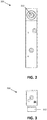
- FIG. 2 illustrates a back view of the manifold 200.
- the manifold input part 212 can be easily seen.
- FIG. 3 illustrates a bottom view of the manifold 200. Again the manifold input part 212 can be easily seen. Id.
- FIG. 1 also illustrates a manifold input part 212 that is adapted for introducing the gas into the manifold.
- the manifold input part 212 may comprise in one example a threaded part for connecting a standard input connector to it.
- Such a standard input connector may be a DIN input connector, although embodiments are not limited thereto and
- FIG. 2 illustrates a back view of the
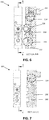
- FIG. 4 illustrates a side view of the manifold 200 as well as a cross-sectional view along line A-A.
- part of the pressure reduction component 214 is shown, where the pressure of the incoming gas is reduce, so as to obtain a suitable pressure for use in gas delivery.
- the pressure reduction may for example be towards a predetermined pressure, such as for example to a pressure in a range between 1 bar and 2 bar, such as for example 1.5 bar or for example 2 bar.
- FIG. 5 illustrates a top view of the manifold. wherein again the manifold input part 212 can be seen.
- FIG. 6 illustrates a front view of the manifold with a cross-section line B-B for which the cross-sectional view along line B-B is also shown.
- FIG. 7 illustrates the same front view of the manifold but with cross-section line C-C for which the cross-sectional view along line C-C is also shown. Based on these drawings, the typical flow of the gas can be described.
- the manifold input part 212 can be seen along which the gas enters the manifold. As described above, this component typically may comprise a threaded portion. From the manifold input part 212, the gas is led via one or more channels towards a pressure reduction component 214 for reducing the pressure so as to obtain a pressure that is suitable for use in gas delivery. From the pressure reduction component 214, the gas is again led via one or more channels towards an absolute pressure sensor 216. This absolute pressure sensor 216 may allow for evaluating the absolute pressure for the gas.
- the gas is then further led through channels towards a flow sensor 218 for checking the flow that is provided and controlled by a piezo-electrical valve.
- the gas is then further directed to a differential pressure sensor 220.
- the gas is thereafter led to a manifold output part 222.
- the cross-sectional view C-C of FIG. 7 allows to further illustrate the channel used as a safety channel 230 so that in case of non-functioning of one of the components at least a safety gas flow can be obtained.
- the flow thereof will be controlled by a needle valve 232.
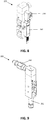
- FIG. 8 the pressure valves of which one 242 is used in the conventional gas stream for controlling the gas flow, which in the present example is a piezo-electric valve, and of which one 240 is used in the safety gas stream for controlling the gas flow, which in the present example is a latching valve, are shown, mounted on the manifold.
- the piezo-electric valve is provided with an electrical connector.
- FIG. 9 illustrates an additional connector 250 which is mounted to manifold input part 212 and an additional connector 252 which is mounted to the manifold output part 222.
- the type of connectors used may depend on the type of gas connection requirements that are valid in the country of use of the gas valve. These connectors may allow for obtaining a country specific, conventional connection.
- FIG. 9 illustrates an additional connector 250 which is mounted to manifold input part 212 and an additional connector 252 which is mounted to the manifold output part 222.
- the type of connectors used may depend on the type of gas connection requirements that are valid in the country of use of the gas valve
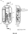
- FIG. 10 illustrates how the manifold 200 is positioned in the housing 260 of the gas valve system 100.
- the manifold is positioned aside a space 262 where typically a battery is positioned. Furthermore, a speaker 264 and an usb connection 266 also is visible.
- the present invention thus also relates to a flow sensor based on a channel wherein one or more local reductions one or more local channel diameter reductions, e.g. for obtaining flow reductions or measuring a flow.
- a local channel diameter reduction may overcome the need for using a honeycomb material in the channel, as typically is required in conventional systems.
- the local channel diameter reduction may be provided by local protrusions of the channel wall into the channel.
- the channel may comprise openings in the channel wall before and after the local channel diameter reduction, to which a flow sensor can be coupled for measuring the flow of the medical gas in a bypass channel.
- the opening in the channel wall may have an axial direction perpendicular to the overall longitudinal direction of the gas channel or they may have an axial direction non-perpendicular to the overall longitudinal direction of the gas channel.
- the angle with respect to the overall longitudinal direction of the gas channel may be such that the amount of disturbance of the gas flow in the main channel is limited.
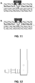
- FIG. 11 two examples A and B of such a configuration is shown in FIG. 11 .
- a flow sensor for measurement of a gas flow is described.
- the flow sensor comprises one or more channels for guiding the gas between an input and an output of the one or more channels.
- the one or more channels comprise one or more local channel diameter reductions and the channel comprises openings in the channel wall before and after the local channel diameter reduction, to which a flow sensor can be coupled for measuring the flow of the medical gas in a bypass channel.
- the orifice ring or channel diameter reduction reduces from a diameter of 4.7mm to 3.5mm and enlarges again to 4.7mm.
- the present invention also relates to a manifold as described in the first aspect, Similar features as described for the first aspect may be present, leading to the same advantages.
- FIG. 12 a further example of a gas valve system is illustrated in FIG. 12 .
- the gas valve system is similar to the gas valve systems as described above, but the manifold input part is positioned at a relative different position compared to the examples already illustrated.
- the manifold input part is positioned more at a bottom side of the gas valve system. This illustrates that the exact position where the manifold input part is positioned relative to the housing is not limited.
- the inner components of the manifold may be rearranged with respect to the housing, or may be as illustrated in the examples above whereby an additional connection tube or channel between the manifold input part and for example a pressure reduction component, or if the pressure reduction component is positioned outside the gas valve system, a first sensor of the gas valve system.
- the manifold input part may be shiftable with respect to the housing, so that the relative position can be adjusted depending on the local environment and/or application.
- the gas reduction component has the function of bringing the gas pressure to a pressure that can be used for gas therapy.
- the working principle of the pressure reduction component may be as followed.
- the gas inlet 1 allows the gas to enter at its typical input pressure, which may be around 5 bar or around 6 bar depending on local conditions.
- the gas flows to he actuator via channel 2 being a connection in the actuator to the space 3 in the actuator. In this room the pressure builds up till a predetermined pressure sufficiently high for use in gas valve therapy, such as for example 2 bar.
- a calibrated spring 4 When the predetermined pressure is reached, a calibrated spring 4 is pressed, such that the gas flow is limited by a closing element 5, such as for example a rubber stopping element.
- the calibrated spring allows for the relative movement of the closing element 5 with respect to the gas inlet 1. This process occurs fast and repetitively. In this way, the pressure in the channels can be controlled and the pressure that is delivered is determined by the calibrated spring, i.e. by the power required for pressing the calibrated spring.
- the space 6 is in contact with the environment. The appropriate gas input pressure and output pressure can be obtained based on selection of the proper spring and proper dimensions of the system.
- one aspect of the present invention which may be considered in combination with the manifold based gas pressure valve but also with any other type of gas valve system, relates to a gas valve system wherein a gas pressure reduction component is provided allowing reducing the gas pressure from between10 bar and 3 bar, e.g. from between 6 bar and 3 bar, e.g. from about 5 bar or 6 bar, to a predetermined gas pressure for use in gas therapy or other gas delivery applications.
- the system may be adapted for using a gas reduction component as the one described above.
- the gas pressure reduction element may be part of the gas valve system, it also may in one aspect be introduced in a connector element.
- the present invention thus also relates to a connector element for coupling a gas valve system to a pressurized gas bottle or a gas distribution network system, the connector element comprising a pressure reducing element.
- the connector can be a single connector or an additional connector that can be mounted, e.g. clicked or screwed, on an existing connector.
- a pressure reducing component can be embedded in a connector. The latter allows for a compact and user friendly manner for introducing a gas pressure reducing component.
Landscapes
- Health & Medical Sciences (AREA)
- Emergency Medicine (AREA)
- Pulmonology (AREA)
- Engineering & Computer Science (AREA)
- Anesthesiology (AREA)
- Biomedical Technology (AREA)
- Heart & Thoracic Surgery (AREA)
- Hematology (AREA)
- Life Sciences & Earth Sciences (AREA)
- Animal Behavior & Ethology (AREA)
- General Health & Medical Sciences (AREA)
- Public Health (AREA)
- Veterinary Medicine (AREA)
- Lift Valve (AREA)
Priority Applications (6)
| Application Number | Priority Date | Filing Date | Title |
|---|---|---|---|
| EP20796801.7A EP4048147A1 (fr) | 2019-10-22 | 2020-10-22 | Mesures de paramètres vitaux pour des patients nécessitant peu de soins |
| PCT/EP2020/079837 WO2021078913A1 (fr) | 2019-10-22 | 2020-10-22 | Mesures de paramètres vitaux pour des patients nécessitant peu de soins |
| EP20797439.5A EP4048359A1 (fr) | 2019-10-22 | 2020-10-22 | Système de valve de gaz avec collecteur |
| PCT/EP2020/079838 WO2021078914A1 (fr) | 2019-10-22 | 2020-10-22 | Système de valve de gaz avec collecteur |
| US17/771,210 US20220361753A1 (en) | 2019-10-22 | 2020-10-22 | Vital parameter measurements for low care patients |
| US17/727,417 US20220241529A1 (en) | 2019-10-22 | 2022-04-22 | Gas valve system with manifold |
Applications Claiming Priority (1)
| Application Number | Priority Date | Filing Date | Title |
|---|---|---|---|
| EP19209878 | 2019-11-18 |
Publications (1)
| Publication Number | Publication Date |
|---|---|
| EP3821933A1 true EP3821933A1 (fr) | 2021-05-19 |
Family
ID=68618004
Family Applications (1)
| Application Number | Title | Priority Date | Filing Date |
|---|---|---|---|
| EP19220019.4A Withdrawn EP3821933A1 (fr) | 2019-10-22 | 2019-12-30 | Système de valve de gaz avec capteur de flux |
Country Status (1)
| Country | Link |
|---|---|
| EP (1) | EP3821933A1 (fr) |
Citations (5)
| Publication number | Priority date | Publication date | Assignee | Title |
|---|---|---|---|---|
| US790888A (en) * | 1901-03-18 | 1905-05-30 | Walter Ferris | Fluid-meter. |
| WO2009073410A1 (fr) * | 2007-11-30 | 2009-06-11 | Honeywell International Inc. | Capteur de flux d'air à tube de pitot pour réduire une chute de pression |
| WO2013071370A1 (fr) * | 2011-11-18 | 2013-05-23 | Colin Dunlop | Procédé et appareil facilitant l'administration d'un anesthésique |
| WO2015177381A2 (fr) * | 2014-05-23 | 2015-11-26 | Penlon Limited | Vaporisateur |
| US20170016752A1 (en) * | 2015-07-15 | 2017-01-19 | Honeywell International Inc. | Flow sensor |
-
2019
- 2019-12-30 EP EP19220019.4A patent/EP3821933A1/fr not_active Withdrawn
Patent Citations (5)
| Publication number | Priority date | Publication date | Assignee | Title |
|---|---|---|---|---|
| US790888A (en) * | 1901-03-18 | 1905-05-30 | Walter Ferris | Fluid-meter. |
| WO2009073410A1 (fr) * | 2007-11-30 | 2009-06-11 | Honeywell International Inc. | Capteur de flux d'air à tube de pitot pour réduire une chute de pression |
| WO2013071370A1 (fr) * | 2011-11-18 | 2013-05-23 | Colin Dunlop | Procédé et appareil facilitant l'administration d'un anesthésique |
| WO2015177381A2 (fr) * | 2014-05-23 | 2015-11-26 | Penlon Limited | Vaporisateur |
| US20170016752A1 (en) * | 2015-07-15 | 2017-01-19 | Honeywell International Inc. | Flow sensor |
Similar Documents
| Publication | Publication Date | Title |
|---|---|---|
| EP2701821B1 (fr) | Ensembles de raccords | |
| CN103781509A (zh) | 鲁尔接头 | |
| US8099856B2 (en) | Self-crimping fill tube assembly | |
| US20210156776A1 (en) | Pressure test apparatus | |
| EP2185069B1 (fr) | Ensemble électropneumatique s'utilisant dans un système de mesure respiratoire | |
| CN109069732A (zh) | 微流限流器组合件及其制造方法 | |
| US20070068872A1 (en) | Nano-flow liquid chromatographic apparatus having robust capillary tubing | |
| CN109489741A (zh) | 流体流量分段测量装置及方法 | |
| CN103512777A (zh) | 用于气体传感器的采样的气动部件 | |
| CA3169496A1 (fr) | Ligne de raccordement de perfusion | |
| US7325463B2 (en) | Fluid sensor assembly | |
| US20080199337A1 (en) | Administration set with two keys | |
| CN103712731B (zh) | 高压流体联接器 | |
| US20220241529A1 (en) | Gas valve system with manifold | |
| CN109404567A (zh) | 一种三通电磁阀 | |
| ES2702483T3 (es) | Dispositivo para suministro controlado de un gas medicinal, con unión de salida reemplazable, y método para la fabricación de dicho dispositivo | |
| CN205580530U (zh) | 医疗仪器用喷射式流量检测装置 | |
| CN212327143U (zh) | 线路管路连接结构及呼吸机 | |
| CN212480438U (zh) | 一种测温测压法兰 | |
| CN219830178U (zh) | 一种固定牢靠的差压表气嘴结构 | |
| CN202179758U (zh) | 一种手术室气体终端箱 | |
| CN109723860A (zh) | 电磁阀及热水器 | |
| CN219071652U (zh) | 一种高低压氧气输出结构及呼吸机 | |
| CN224003269U (zh) | 一种磁吸膜片式充灌阀 | |
| CN202066534U (zh) | 无引压管线的标准孔板节流装置引压装置 |
Legal Events
| Date | Code | Title | Description |
|---|---|---|---|
| PUAI | Public reference made under article 153(3) epc to a published international application that has entered the european phase |
Free format text: ORIGINAL CODE: 0009012 |
|
| STAA | Information on the status of an ep patent application or granted ep patent |
Free format text: STATUS: THE APPLICATION HAS BEEN PUBLISHED |
|
| AK | Designated contracting states |
Kind code of ref document: A1 Designated state(s): AL AT BE BG CH CY CZ DE DK EE ES FI FR GB GR HR HU IE IS IT LI LT LU LV MC MK MT NL NO PL PT RO RS SE SI SK SM TR |
|
| STAA | Information on the status of an ep patent application or granted ep patent |
Free format text: STATUS: REQUEST FOR EXAMINATION WAS MADE |
|
| 17P | Request for examination filed |
Effective date: 20211119 |
|
| RBV | Designated contracting states (corrected) |
Designated state(s): AL AT BE BG CH CY CZ DE DK EE ES FI FR GB GR HR HU IE IS IT LI LT LU LV MC MK MT NL NO PL PT RO RS SE SI SK SM TR |
|
| STAA | Information on the status of an ep patent application or granted ep patent |
Free format text: STATUS: EXAMINATION IS IN PROGRESS |
|
| RIC1 | Information provided on ipc code assigned before grant |
Ipc: A61M 16/00 20060101ALN20220113BHEP Ipc: A61M 16/20 20060101ALI20220113BHEP Ipc: A61M 16/08 20060101AFI20220113BHEP |
|
| 17Q | First examination report despatched |
Effective date: 20220208 |
|
| REG | Reference to a national code |
Ref country code: DE Ref legal event code: R079 Free format text: PREVIOUS MAIN CLASS: A61M0016100000 Ipc: A61M0016080000 |
|
| RIC1 | Information provided on ipc code assigned before grant |
Ipc: A61M 16/00 20060101ALN20230411BHEP Ipc: A61M 16/20 20060101ALI20230411BHEP Ipc: A61M 16/08 20060101AFI20230411BHEP |
|
| RIC1 | Information provided on ipc code assigned before grant |
Ipc: A61M 16/00 20060101ALN20230419BHEP Ipc: A61M 16/20 20060101ALI20230419BHEP Ipc: A61M 16/08 20060101AFI20230419BHEP |
|
| STAA | Information on the status of an ep patent application or granted ep patent |
Free format text: STATUS: THE APPLICATION IS DEEMED TO BE WITHDRAWN |
|
| 18D | Application deemed to be withdrawn |
Effective date: 20231003 |