EP3822009A1 - Indexierbares bohrwerkzeug - Google Patents
Indexierbares bohrwerkzeug Download PDFInfo
- Publication number
- EP3822009A1 EP3822009A1 EP18929994.4A EP18929994A EP3822009A1 EP 3822009 A1 EP3822009 A1 EP 3822009A1 EP 18929994 A EP18929994 A EP 18929994A EP 3822009 A1 EP3822009 A1 EP 3822009A1
- Authority
- EP
- European Patent Office
- Prior art keywords
- cutting
- drilling tool
- blade
- point
- central
- Prior art date
- Legal status (The legal status is an assumption and is not a legal conclusion. Google has not performed a legal analysis and makes no representation as to the accuracy of the status listed.)
- Pending
Links
Images



Classifications
-
- B—PERFORMING OPERATIONS; TRANSPORTING
- B23—MACHINE TOOLS; METAL-WORKING NOT OTHERWISE PROVIDED FOR
- B23B—TURNING; BORING
- B23B51/00—Tools for drilling machines
-
- B—PERFORMING OPERATIONS; TRANSPORTING
- B23—MACHINE TOOLS; METAL-WORKING NOT OTHERWISE PROVIDED FOR
- B23B—TURNING; BORING
- B23B51/00—Tools for drilling machines
- B23B51/0006—Drills with cutting inserts
- B23B51/0011—Drills with cutting inserts with radially inner and outer cutting inserts
-
- B—PERFORMING OPERATIONS; TRANSPORTING
- B23—MACHINE TOOLS; METAL-WORKING NOT OTHERWISE PROVIDED FOR
- B23B—TURNING; BORING
- B23B51/00—Tools for drilling machines
- B23B51/0006—Drills with cutting inserts
- B23B51/0007—Drills with cutting inserts with exchangeable cutting insert
- B23B51/0008—Drills with cutting inserts with exchangeable cutting insert with indexable or reversible cutting inserts
-
- B—PERFORMING OPERATIONS; TRANSPORTING
- B23—MACHINE TOOLS; METAL-WORKING NOT OTHERWISE PROVIDED FOR
- B23C—MILLING
- B23C5/00—Milling-cutters
- B23C5/16—Milling-cutters characterised by physical features other than shape
- B23C5/20—Milling-cutters characterised by physical features other than shape with removable cutter bits or teeth or cutting inserts
- B23C5/202—Plate-like cutting inserts with special form
-
- B—PERFORMING OPERATIONS; TRANSPORTING
- B23—MACHINE TOOLS; METAL-WORKING NOT OTHERWISE PROVIDED FOR
- B23B—TURNING; BORING
- B23B2200/00—Details of cutting inserts
- B23B2200/04—Overall shape
- B23B2200/0404—Hexagonal
- B23B2200/0419—Hexagonal trigonal
-
- B—PERFORMING OPERATIONS; TRANSPORTING
- B23—MACHINE TOOLS; METAL-WORKING NOT OTHERWISE PROVIDED FOR
- B23B—TURNING; BORING
- B23B2200/00—Details of cutting inserts
- B23B2200/04—Overall shape
- B23B2200/0438—Octagonal
-
- B—PERFORMING OPERATIONS; TRANSPORTING
- B23—MACHINE TOOLS; METAL-WORKING NOT OTHERWISE PROVIDED FOR
- B23B—TURNING; BORING
- B23B2200/00—Details of cutting inserts
- B23B2200/04—Overall shape
- B23B2200/0471—Square
Definitions
- the present invention relates to the field of metal cutting, in particular to an indexable drilling tool.
- Cutting edges of an indexable drilling tool are asymmetric with respect to a central axis, and a cutting portion thereof comprises an inner blade and an outer blade.
- the inner blade and the outer blade complete machining of respective different cutting areas. Specifically, the inner blade completes removal of materials at a central area, and the outer blade completes removal of peripheral materials.
- a linear velocity of a cutting edge of the drilling tool increases with an increase of a radius. Therefore, the linear velocity at the central area of the inner blade approaches zero, the cutting edge at the central area of the drilling tool has severe friction, and much more materials are removed from the cutting edge near a peripheral surface of the cutter body than that from a center.
- the inner blade and the outer blade have different structures or have identical structure with different mounting dimensions.
- wear resistance and impact resistance of the inner blade and the outer blades can be improved to a certain extent through such a structure, it is hard to balance a radial force of a cutting tool when the inner blade and the outer blade are involved in the cutting due to independence of the inner blade and the outer blade mounted on the cutter body.
- Unbalance of a cutting force tends to produce cutting vibration, which not only reduces quality of a machining surface and dimensional accuracy of a hole, but also greatly reduces a service life of the indexable drilling tool.
- radial balance of the inner blade and the outer blade is not only affected by the cutting force, but also directly related to an inclination degree of the inner blade and the outer blade. More importantly, since wear of the inner blade and the outer blade is asynchronous, asynchronous changes in the wear may also break the balance between the inner blade and the outer blade.
- the radial balance refers to a double radial balance in a cutting plane and in an end plane. Due to complex blade structure, great difference in cutting linear velocity between the inner blade and the outer blade, and interaction of the radial balance between the cutting plane and the end plane, it is very hard to ensure the radial force balance of the cutting plane and the end plane of the drilling tool.
- a technical problem to be solved by the invention is to overcome shortcomings of the prior art and provide an indexable drilling tool with small cutting vibration, strong radial balance ability, good machining surface quality and high dimensional accuracy.
- the present invention adopts the following technical solution.
- An indexable drilling tool comprises a cutter body, an outer blade and an inner blade.
- the cutter body comprises a shank portion, a cutting end portion and a peripheral surface located between the shank portion and the cutting end portion.
- the shank portion and the peripheral surface are symmetric with respect to a rotating central axis of the cutter body.
- the cutting end portion is provided with a central groove and a circumferential groove communicated with a spiral groove on the peripheral surface, the central groove is arranged adjacent to the rotating central axis, and the circumferential groove is arranged adjacent to the peripheral surface.
- the outer blade is arranged in the circumferential groove for machining an outer ring area of a hole
- the inner blade is arranged in the central groove for machining a central area of the hole.
- the inner blade is surrounded by a first upper surface, a first lower surface and a first side surface connecting the first upper surface and the first lower surface.
- the first upper surface intersects with the first side surface to form multiple identical inner cutting edges.
- a cutting area of the inner cutting edge served as a main cutting edge is located between a central inner point and a central outer point on the inner cutting edge.
- an inner convex cutting portion having a maximum cutting depth is arranged between the central inner point and the central outer point.
- a distance between the central inner point and the inner convex cutting portion in an axial direction of the indexable drilling tool is H1
- a distance between the central outer point and the inner convex cutting portion in an axial direction of the indexable drilling tool is H2, which meets the following requirement: 0.9H2 ⁇ H1 ⁇ 1.1H2.
- the outer blade is surrounded by a second upper surface, a second lower surface and a second side surface connecting the second upper surface and the second lower surface.
- the second upper surface intersects with the second side surface to form multiple identical outer cutting edges.
- a distance between the peripheral inner point and the outer convex cutting portion in the axial direction of the indexable drilling tool is H1'
- a distance between the peripheral outer point and the outer convex cutting portion in the axial direction of the indexable drilling tool is H2', which meets the following requirement: 0.95H1' ⁇ H2' ⁇ 1.1H1'.
- a machining diameter of the indexable drilling tool is D.
- the inner convex cutting portion cuts into a workpiece earlier than the outer convex cutting portion, and a cutting depth difference is H3, which meets the following requirement: 0.003D ⁇ H3 ⁇ 0.01D.
- a cutting width of the inner blade is Ae
- a cutting width of the outer blade is Ae', which meets the following requirement: 0.8Ae' ⁇ Ae ⁇ 0.95 Ae'.
- a distance between the inner convex cutting portion on the inner cutting edge as the main cutting edge and the central inner point corresponding to the inner convex cutting portion is d1
- a distance between the inner convex cutting portion on the inner cutting edge as the main cutting edge and the central outer point corresponding to the inner convex cutting portion is d2, which meets the following requirement: 1mm ⁇ d2 ⁇ d1.
- a distance between the outer convex cutting portion on the outer cutting edge as the main cutting edge and the peripheral inner point corresponding to the outer convex cutting portion is dl'
- a distance between the outer convex cutting portion on the outer cutting edge as the main cutting edge and the peripheral outer point corresponding to the outer convex cutting portion is d2' respectively, which meets the following requirement: 0.3d2' ⁇ d1' ⁇ d2'.
- a single inner cutting edge of the inner blade is provided with a number M of inner convex cutting portions, and each of the outer cutting edges of the outer blade is provided with a number N of outer convex cutting portions, which meets the following requirements: 1 ⁇ M ⁇ 3, and 1 ⁇ N ⁇ 3.
- the first upper surface intersects with the first side surface to form three or four groups of the inner cutting edges.
- Each inner cutting edge comprises two inner straight edges and one inner corner edge.
- the inner convex cutting portion is formed between the two inner straight edges, and the inner straight edges adjacent to the inner cutting edges are connected by the inner corner edge.
- the second upper surface intersects with the second side surface to form three or four groups of the identical outer cutting edges.
- Each outer cutting edge comprises two outer straight edges and one outer corner edge.
- the outer convex cutting portion is formed between the two outer straight edges, and the outer straight edges adjacent to the outer cutting edges are connected by the outer corner edge.
- the outer blade is surrounded by a second upper surface, a second lower surface and a second side surface connecting the second upper surface and the second lower surface.
- the second upper surface intersects with the second side surface to form multiple identical outer cutting edges.
- Each outer cutting edge comprises one outer straight edge and one outer corner edge, and the outer straight edges of adjacent outer cutting edges are connected by the outer corner edge.
- a machining diameter of the indexable drilling tool is D.
- the inner convex cutting portion cuts into a workpiece earlier than the outer cutting edges, and a cutting depth difference is H3, which meets the following requirement: 0.003D ⁇ H3 ⁇ 0.01D.
- an included angle between the outer blade and the inner blade is ⁇ , which meets the following requirement: 165° ⁇ 178°.
- the present invention has the following advantages.
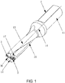
- FIG. 1 to FIG. 4 show a first embodiment of the indexable drilling tool of the present invention, comprising a cutter body 1, an outer blade 2 and an inner blade 3.
- the cutter body 1 comprises a shank portion 11, a cutting end portion 12 and a peripheral surface 13 located between the shank portion 11 and the cutting end portion 12.
- the shank portion 11 and the peripheral surface 13 are symmetric with respect to a rotating central axis 14 of the cutter body 1.
- the cutting end portion 12 is provided with a central groove 16 and a circumferential groove 17 communicated with a spiral groove 15 on the peripheral surface 13, the central groove 16 is arranged adjacent to the rotating central axis 14, and the circumferential groove 17 is arranged adjacent to the peripheral surface 13.
- the outer blade 2 is arranged in the circumferential groove 17 for machining an outer ring area of a hole
- the inner blade 3 is arranged in the central groove 16 for machining a central area of the hole.
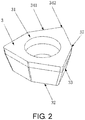
- the inner blade 3 is surrounded by a first upper surface 31, a first lower surface 32 and a first side surface 33 connecting the first upper surface 31 and the first lower surface 32.
- the first upper surface 31 intersects with the first side surface 33 to form multiple identical inner cutting edges 34.
- a cutting area of the inner cutting edge 34 served as a main cutting edge is located between a central inner point 35 and a central outer point 36 on the inner cutting edge 34.
- an inner convex cutting portion 37 having a maximum cutting depth is arranged between the central inner point 35 and the central outer point 36.
- a distance between the central inner point 35 and the inner convex cutting portion 37 in an axial direction of the indexable drilling tool is H1
- a distance between the central outer point 36 and the inner convex cutting portion 37 in an axial direction of the indexable drilling tool is H2, which meets the following requirement: 0.9H2 ⁇ H1 ⁇ 1.1H2.
- An inner convex cutting portion 37 having a maximum cutting depth is arranged between the central inner point 35 and the central outer point 36.
- the cutting force generated by the cutting edges located between the central inner point 35 and the inner convex cutting portion 37 and the radial force generated by the cutting edges located between the central outer point 36 and the inner convex cutting portion 37 are essentially balanced in the cutting plane. That is, regardless of the cutting edge shape, cutting angle, mounting angle and rake angle of the inner blade 3, the inner blade 3 itself can achieve a radial balance in the cutting plane. Therefore, when considering mounting dimensions of the inner blade 3 and the outer blade 2 on the cutter body 1, it is not necessary to consider influence of the cutting edge shape, cutting angle, mounting angle and rake angle of the inner blade 3 on the radial balance thereof in the cutting plane, and it is only necessary to achieve balance of the cutting force in the end plane.
- the mounting dimensions of the inner blade 3 and the outer blade 2 can be obtained more easily, and the radial balance of the indexable drilling tool can be realized. Therefore, the indexable drilling tool has small cutting vibration, good machining surface quality, and high dimensional accuracy. Meanwhile, because the inner blade 3 has achieved the radial balance in the cutting plane, the radial balance of the inner blade 3 in the cutting plane will not be affected even if the inner blade 3 and the outer blade 2 experience asynchronous wear and generate asynchronous change in the cutting force under the influence of the cutting speed, which greatly improves the cutting stability of the inner blade 3 and prolongs the service life of the inner blade 3.
- the outer blade 2 has a similar structure to the inner blade 3. That is, the outer blade 2 is surrounded by a second upper surface 21, a second lower surface 22 and a second side surface 33 connecting the second upper surface 21 and the second lower surface 22.
- the second upper surface 21 intersects with the second side surface 23 to form multiple identical outer cutting edges 24.
- a cutting area of the outer cutting edge 24 served as a main cutting edge is located between a peripheral inner point 25 and a peripheral outer point 26 on the outer cutting edge 24.
- an outer convex cutting portion 27 having a maximum cutting depth is arranged between the peripheral inner point 25 and the peripheral outer point 26.
- An outer convex cutting portion 27 having a maximum cutting depth is arranged between the peripheral inner point 25 and the peripheral outer point 26.
- a cutting force generated by cutting edges located between the peripheral inner point 25 and the outer convex cutting portion 27 is in opposite direction to a cutting force generated by cutting edges located between the peripheral outer point 26 and the outer convex cutting portion 27 in the cutting plane.
- a distance between the peripheral inner point 25 and the outer convex cutting portion 27 in the axial direction of the indexable drilling tool is H1'
- the cutting force generated by the cutting edges located between the peripheral inner point 25 and the outer convex cutting portion 27 and the radial force generated by the cutting edges located between the peripheral outer point 26 and the outer convex cutting portion 27 are essentially balanced in the cutting plane. That is, regardless of the cutting edge shape, cutting angle, mounting angle and rake angle of the outer blade 2, the outer blade 2 itself can achieve the radial balance in the cutting plane. That is, the inner blade 3 and the outer blade 2 can achieve the radial balance in the cutting plane.
- the mounting dimensions of the inner blade 3 and the outer blade 2 it is not necessary to consider influence of the cutting edge shape, cutting angle, mounting angle and rake angle of the inner blade 3 and the outer blade 2 on the radial balance thereof in the cutting plane, and it is only necessary to achieve the balance of the cutting force in the end plane.
- the mounting dimensions of the inner blade 3 and the outer blade 2 on the cutter body 1 can be obtained more easily, and the radial balance of the indexable drilling tool can be realized. Therefore, the indexable drilling tool has small cutting vibration, good machining surface quality, and high dimensional accuracy.
- the radial balance of the inner blade 3 and the outer blade 2 in the cutting plane will not be affected even if the inner blade 3 and the outer blade 2 experience asynchronous wear and generate asynchronous change in the cutting force under the influence of the cutting speed, which greatly improves the cutting stability of the inner blade 3 and the outer blade 2, prolongs the service life of the inner blade 3 and the outer blade 2, prolongs the service life of the indexable drilling tool, and improves the machining surface quality and the dimensional accuracy while always guaranteeing consistency of the machining surface quality and the dimensional accuracy.
- a machining diameter of the indexable drilling tool is D.
- the main cutting forces of the inner blade 3 and the outer blade 2 should be essentially equal.
- the main cutting forces of the inner blade 3 and the outer blade 2 do not completely depend on a cutting width.
- the cutting width of the inner blade 3 is Ae
- a distance between the inner convex cutting portion 37 on the inner cutting edge 34 as the main cutting edge and the central inner point 35 corresponding to the inner convex cutting portion 37 is d1
- a distance between the outer convex cutting portion 27 on the outer cutting edge 24 as the main cutting edge and the peripheral inner point 25 corresponding to the outer convex cutting portion 27 is d1'.
- Each inner cutting edge 34 of the inner blade 3 is provided with a number M of inner convex cutting portions 37
- each outer cutting edge 24 of the outer blade 2 is provided with a number N of outer convex cutting portions 27, which meets the following requirements: 1 ⁇ M ⁇ 3, and 1 ⁇ N ⁇ 3.
- the first upper surface 31 intersects with the first side surface 33 to form three groups of inner cutting edges 34.
- the inner cutting edge 34 comprises two inner straight edges 341 and one inner corner edge 342 connecting the two inner straight edges 341.
- the inner convex cutting portion 37 is formed between the two inner straight edges 341, and the inner straight edges 341 adjacent to the inner cutting edges 34 are connected by the inner corner edge 342.
- the second upper surface 21 intersects with the second side surface 23 to form three groups of identical outer cutting edges 24.
- Each outer cutting edge 24 comprises two outer straight edges 241 and one outer corner edge 242 connecting the two outer straight edges 241.
- the outer convex cutting portion 27 is formed between the two outer straight edges 241, and the outer straight edges 241 adjacent to the outer cutting edges 24 are connected by the outer corner edge 242.
- an included angle between the outer blade 2 and the inner blade 3 is ⁇
- the inner blade 3 and the outer blade 2 achieve the radial balance in the cutting surface, and it is not necessary to adjust the ⁇ to adjust a main cutting radial component force in the end plane of the inner blade 3 to balance a component force of the outer blade 2 on the end cutting plane.
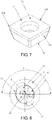
- FIG. 5 to FIG. 9 show a second embodiment of the indexable drilling tool of the present invention.
- the inner blade 3 has a different structure from the outer blade 2.
- the outer blade 2 is surrounded by a second upper surface 21, a second lower surface 22 and a second side surface 23 connecting the second upper surface 21 and the second lower surface 22, and the second upper surface 21 intersects with the second side surface 23 to form four identical outer cutting edges 24.
- the outer cutting edge 24 comprises one outer straight edge 241 and one outer corner edge 242.
- the outer straight edge 241 of the outer cutting edge 24 is connected by the outer corner edge 242, and the structure of the outer blade 2 is simpler.
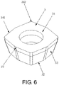
- the structure of the inner blade 3 is shown in FIG. 6 .
- the first upper surface 31 intersects with the first side surface 33 to form four groups of inner cutting edges 34.
- the inner cutting edge 34 comprises two inner straight edges 341 and one inner corner edge 342.
- the inner convex cutting portion 37 is formed between the two inner straight edges 341.
- the inner straight edges 341 adjacent to the inner cutting edges 34 are connected by the inner corner edge 342. Similar to the principle of the first embodiment, the inner blade 3 itself can achieve the radial balance in the cutting plane.
- a machining diameter of the indexable drilling tool is D.
Landscapes
- Engineering & Computer Science (AREA)
- Mechanical Engineering (AREA)
- Drilling Tools (AREA)
Applications Claiming Priority (2)
| Application Number | Priority Date | Filing Date | Title |
|---|---|---|---|
| CN201810922447.2A CN109158664B (zh) | 2018-08-14 | 2018-08-14 | 一种可转位钻孔刀具 |
| PCT/CN2018/104112 WO2020034270A1 (zh) | 2018-08-14 | 2018-09-05 | 一种可转位钻孔刀具 |
Publications (2)
| Publication Number | Publication Date |
|---|---|
| EP3822009A1 true EP3822009A1 (de) | 2021-05-19 |
| EP3822009A4 EP3822009A4 (de) | 2022-04-13 |
Family
ID=64895576
Family Applications (1)
| Application Number | Title | Priority Date | Filing Date |
|---|---|---|---|
| EP18929994.4A Pending EP3822009A4 (de) | 2018-08-14 | 2018-09-05 | Indexierbares bohrwerkzeug |
Country Status (4)
| Country | Link |
|---|---|
| US (1) | US20210291283A1 (de) |
| EP (1) | EP3822009A4 (de) |
| CN (1) | CN109158664B (de) |
| WO (1) | WO2020034270A1 (de) |
Families Citing this family (4)
| Publication number | Priority date | Publication date | Assignee | Title |
|---|---|---|---|---|
| CN114789272B (zh) * | 2022-06-07 | 2023-12-22 | 株洲钻石切削刀具股份有限公司 | 一种钻孔刀具 |
| CN115365527B (zh) * | 2022-09-21 | 2025-07-08 | 浙江欧迪恩传动科技股份有限公司 | 一种适用于车床的刀具及对轴类零件端面加工的方法 |
| CN116748569A (zh) * | 2023-06-21 | 2023-09-15 | 浙江欣兴工具股份有限公司 | 一种可转位钻头的刀片组合及可转位钻头 |
| CN118060604B (zh) * | 2024-04-18 | 2024-07-05 | 常州中昇工具有限公司 | 一种基于汽车曲轴加工用组合式阶梯铣刀 |
Family Cites Families (18)
| Publication number | Priority date | Publication date | Assignee | Title |
|---|---|---|---|---|
| DE7830277U1 (de) * | 1978-10-11 | 1980-03-20 | Komet Stahlhalter- Und Werkzeugfabrik Robert Breuning Gmbh, 7122 Besigheim | Bohrwerkzeug fuer bohrungen in metallvollmaterial |
| US4659264A (en) * | 1982-07-06 | 1987-04-21 | Kennametal Inc. | Drill and indexable carbide insert therefor |
| DE4018043A1 (de) * | 1990-06-06 | 1991-12-12 | Krupp Widia Gmbh | Bohrwerkzeug |
| CN2113846U (zh) * | 1991-07-30 | 1992-08-26 | 西安石油学院 | 硬质合金可转位钻-扩两用刀具 |
| CN2160487Y (zh) * | 1993-07-31 | 1994-04-06 | 李林 | 高速可转位钻具 |
| SE504315C2 (sv) * | 1994-05-09 | 1997-01-13 | Sandvik Ab | Borr för metallborrning |
| DE19522837A1 (de) * | 1995-06-23 | 1997-01-02 | Beck August Gmbh Co | Bohrwerkzeug |
| DE19522836A1 (de) * | 1995-06-23 | 1997-01-02 | Beck August Gmbh Co | Bohrwerkzeug |
| JPH09290312A (ja) * | 1996-04-26 | 1997-11-11 | Mitsubishi Materials Corp | スローアウェイチップおよびスローアウェイ式穴明け工具 |
| JP4884048B2 (ja) * | 2006-03-27 | 2012-02-22 | 京セラ株式会社 | スローアウェイドリル |
| JP4976181B2 (ja) * | 2006-12-25 | 2012-07-18 | 住友電工ハードメタル株式会社 | スローアウェイドリルのチップ配置方法 |
| SE530823C2 (sv) * | 2007-01-29 | 2008-09-16 | Sandvik Intellectual Property | Vändskärsborr och centrumskär härför |
| US8979443B2 (en) * | 2007-12-28 | 2015-03-17 | Kyocera Corporation | Insert for drill |
| JP5365298B2 (ja) * | 2008-03-31 | 2013-12-11 | 三菱マテリアル株式会社 | ドリル用インサートおよびインサートドリル |
| CN102773526B (zh) * | 2010-08-31 | 2014-05-28 | 株洲钻石切削刀具股份有限公司 | 一种可调节切削回转半径的刀具组件 |
| KR101222291B1 (ko) * | 2011-07-20 | 2013-01-15 | 대구텍 유한회사 | 드릴 공구 |
| CN204135419U (zh) * | 2014-09-17 | 2015-02-04 | 宁波市荣科迈特数控刀具有限公司 | 一种精镗复合钻 |
| EP3034215B1 (de) * | 2014-12-19 | 2018-01-31 | Sandvik Intellectual Property AB | Schneideinsatz und Bohrwerkzeug |
-
2018
- 2018-08-14 CN CN201810922447.2A patent/CN109158664B/zh active Active
- 2018-09-05 WO PCT/CN2018/104112 patent/WO2020034270A1/zh not_active Ceased
- 2018-09-05 EP EP18929994.4A patent/EP3822009A4/de active Pending
- 2018-09-05 US US17/266,620 patent/US20210291283A1/en active Pending
Also Published As
| Publication number | Publication date |
|---|---|
| US20210291283A1 (en) | 2021-09-23 |
| WO2020034270A1 (zh) | 2020-02-20 |
| CN109158664A (zh) | 2019-01-08 |
| CN109158664B (zh) | 2021-06-18 |
| EP3822009A4 (de) | 2022-04-13 |
Similar Documents
| Publication | Publication Date | Title |
|---|---|---|
| CN109158665B (zh) | 可转位钻孔刀具 | |
| EP3822009A1 (de) | Indexierbares bohrwerkzeug | |
| KR930001459B1 (ko) | 회전식 절삭공구 | |
| CN101326026B (zh) | 正弦角旋转切削工具 | |
| EP3299102B1 (de) | Werkzeugkörper in kombination mit einem ersten schneideinsatz und einem zweiten schneideinsatz | |
| KR102029564B1 (ko) | T 슬롯 커터 | |
| CN103028770B (zh) | 铣刀及其切削刀片 | |
| EP3175945B1 (de) | Schneideeinsatz und schneidewerkzeug mit auswechselbarer schneidekante | |
| TWI776939B (zh) | 具有彎曲副切削刃及角切削刃的方形切削刀塊、及旋轉切削刀具 | |
| US11890687B2 (en) | Milling tool and workpiece machining method | |
| KR20170033896A (ko) | 양면형 절삭 인서트 및 밀링 공구 | |
| JP2019524456A (ja) | 表および裏面取り用回転式フライスのための星形切削インサート | |
| EP3930946B1 (de) | Wendeschneidplatte | |
| JP4860882B2 (ja) | フライス工具 | |
| WO2015080168A1 (ja) | 切削インサート及び刃先交換式切削工具 | |
| JP2014520679A (ja) | ドリル工具 | |
| CN210525162U (zh) | 切割锯 | |
| JP2014231115A (ja) | エンドミル | |
| WO2016163341A1 (ja) | 切削インサートおよび刃先交換式切削工具 | |
| CN106694962B (zh) | 一种钻削刀具 | |
| JP5633395B2 (ja) | 切削インサートおよび刃先交換式切削工具 | |
| WO1992003243A1 (fr) | Foret | |
| CN208450681U (zh) | 用于加工石墨工件的铣刀 | |
| JPH0232329Y2 (de) | ||
| JP4652187B2 (ja) | 回転切削工具 |
Legal Events
| Date | Code | Title | Description |
|---|---|---|---|
| STAA | Information on the status of an ep patent application or granted ep patent |
Free format text: STATUS: THE INTERNATIONAL PUBLICATION HAS BEEN MADE |
|
| PUAI | Public reference made under article 153(3) epc to a published international application that has entered the european phase |
Free format text: ORIGINAL CODE: 0009012 |
|
| STAA | Information on the status of an ep patent application or granted ep patent |
Free format text: STATUS: REQUEST FOR EXAMINATION WAS MADE |
|
| 17P | Request for examination filed |
Effective date: 20210211 |
|
| AK | Designated contracting states |
Kind code of ref document: A1 Designated state(s): AL AT BE BG CH CY CZ DE DK EE ES FI FR GB GR HR HU IE IS IT LI LT LU LV MC MK MT NL NO PL PT RO RS SE SI SK SM TR |
|
| DAV | Request for validation of the european patent (deleted) | ||
| DAX | Request for extension of the european patent (deleted) | ||
| A4 | Supplementary search report drawn up and despatched |
Effective date: 20220316 |
|
| RIC1 | Information provided on ipc code assigned before grant |
Ipc: B23B 51/00 20060101AFI20220309BHEP |
|
| STAA | Information on the status of an ep patent application or granted ep patent |
Free format text: STATUS: EXAMINATION IS IN PROGRESS |
|
| 17Q | First examination report despatched |
Effective date: 20251028 |