EP3822017A2 - Kaltpressschweissvorrichtung, spulenherstellungsvorrichtung, spule und verfahren zur herstellung davon - Google Patents
Kaltpressschweissvorrichtung, spulenherstellungsvorrichtung, spule und verfahren zur herstellung davon Download PDFInfo
- Publication number
- EP3822017A2 EP3822017A2 EP20216266.5A EP20216266A EP3822017A2 EP 3822017 A2 EP3822017 A2 EP 3822017A2 EP 20216266 A EP20216266 A EP 20216266A EP 3822017 A2 EP3822017 A2 EP 3822017A2
- Authority
- EP
- European Patent Office
- Prior art keywords
- coil
- holding part
- conductors
- helical
- flat
- Prior art date
- Legal status (The legal status is an assumption and is not a legal conclusion. Google has not performed a legal analysis and makes no representation as to the accuracy of the status listed.)
- Pending
Links
Images





Classifications
-
- H—ELECTRICITY
- H02—GENERATION; CONVERSION OR DISTRIBUTION OF ELECTRIC POWER
- H02K—DYNAMO-ELECTRIC MACHINES
- H02K15/00—Processes or apparatus specially adapted for manufacturing, assembling, maintaining or repairing of dynamo-electric machines
- H02K15/30—Manufacture of winding connections
- H02K15/33—Connecting winding sections; Forming leads; Connecting leads to terminals
-
- B—PERFORMING OPERATIONS; TRANSPORTING
- B23—MACHINE TOOLS; METAL-WORKING NOT OTHERWISE PROVIDED FOR
- B23K—SOLDERING OR UNSOLDERING; WELDING; CLADDING OR PLATING BY SOLDERING OR WELDING; CUTTING BY APPLYING HEAT LOCALLY, e.g. FLAME CUTTING; WORKING BY LASER BEAM
- B23K20/00—Non-electric welding by applying impact or other pressure, with or without the application of heat, e.g. cladding or plating
- B23K20/02—Non-electric welding by applying impact or other pressure, with or without the application of heat, e.g. cladding or plating by means of a press ; Diffusion bonding
-
- B—PERFORMING OPERATIONS; TRANSPORTING
- B23—MACHINE TOOLS; METAL-WORKING NOT OTHERWISE PROVIDED FOR
- B23K—SOLDERING OR UNSOLDERING; WELDING; CLADDING OR PLATING BY SOLDERING OR WELDING; CUTTING BY APPLYING HEAT LOCALLY, e.g. FLAME CUTTING; WORKING BY LASER BEAM
- B23K20/00—Non-electric welding by applying impact or other pressure, with or without the application of heat, e.g. cladding or plating
- B23K20/02—Non-electric welding by applying impact or other pressure, with or without the application of heat, e.g. cladding or plating by means of a press ; Diffusion bonding
- B23K20/028—Butt welding
-
- H—ELECTRICITY
- H01—ELECTRIC ELEMENTS
- H01F—MAGNETS; INDUCTANCES; TRANSFORMERS; SELECTION OF MATERIALS FOR THEIR MAGNETIC PROPERTIES
- H01F41/00—Apparatus or processes specially adapted for manufacturing or assembling magnets, inductances or transformers; Apparatus or processes specially adapted for manufacturing materials characterised by their magnetic properties
- H01F41/02—Apparatus or processes specially adapted for manufacturing or assembling magnets, inductances or transformers; Apparatus or processes specially adapted for manufacturing materials characterised by their magnetic properties for manufacturing cores, coils, or magnets
- H01F41/04—Apparatus or processes specially adapted for manufacturing or assembling magnets, inductances or transformers; Apparatus or processes specially adapted for manufacturing materials characterised by their magnetic properties for manufacturing cores, coils, or magnets for manufacturing coils
- H01F41/06—Coil winding
- H01F41/061—Winding flat conductive wires or sheets
-
- B—PERFORMING OPERATIONS; TRANSPORTING
- B23—MACHINE TOOLS; METAL-WORKING NOT OTHERWISE PROVIDED FOR
- B23K—SOLDERING OR UNSOLDERING; WELDING; CLADDING OR PLATING BY SOLDERING OR WELDING; CUTTING BY APPLYING HEAT LOCALLY, e.g. FLAME CUTTING; WORKING BY LASER BEAM
- B23K2101/00—Articles made by soldering, welding or cutting
- B23K2101/36—Electric or electronic devices
- B23K2101/38—Conductors
-
- H—ELECTRICITY
- H01—ELECTRIC ELEMENTS
- H01F—MAGNETS; INDUCTANCES; TRANSFORMERS; SELECTION OF MATERIALS FOR THEIR MAGNETIC PROPERTIES
- H01F27/00—Details of transformers or inductances, in general
- H01F27/28—Coils; Windings; Conductive connections
- H01F27/2847—Sheets; Strips
Definitions
- the present invention relates to: a cold pressure welding apparatus for welding flat plates together by causing the flat plates to be pressurized and deformed; a coil manufacturing apparatus; a coil; and a method of manufacturing the coil.
- Examples of a coil apparatus in which a coil is arranged around a core (stator core) of a stator core (stator) may include electrical devices such as motors, electric generators, and transformers. In such a coil apparatus, it is important to improve the space factor of the coil in the core in order to achieve loss reduction and the miniaturization thereof.
- Coils using rectangular conductors have been known in the art as coils capable of improving space factors in cores.
- the rectangular coil is referred to also as a flatwise (square-winding) coil, a square (square type) coil, an edgewise coil, etc.
- the rectangular coil refers to a coil formed by winding a rectangular conductor having a rectangular cross section perpendicular to the longitudinal direction thereof.
- a method of winding an elongated rectangular conductive wire (square conductive wire) in a generally rectangular shape has been also known in the art as a method of manufacturing a rectangular coil (see Patent Literature 1, for example).
- a method of making a helical structure by repeatedly performing stacking rectangular conductors (flat conductive materials), each having a length corresponding to one coil turn, on each other and joining such layers together by welding means with the upper surface of an end edge in the lower layer and the starting and ending lower surface in the upper layer being overlapped with each other has been also known in the art (see Patent Literature 2, for example).
- a cold pressure welding method has also been known in the art as a method of connecting conductors (see Patent Literature 3, for example).
- corner portions both on the outer peripheral side and the inner peripheral side
- a typical core has a shape of a rectangular column having generally right-angle corner portions. If a coil having rounded corners is arranged around such a core, a space is created between the core and the coil. Such a space deteriorates the heat dissipation performance of the coil apparatus due to its accumulation of heat during the operation of the coil apparatus. Consequently, due to increased coil resistance, the coil apparatus fails to achieve high efficiency.
- corner portions have limitations on improvement in coil space factor.
- the outer periphery of the rectangular conductive wire used in the coil is coated with an insulating resin beforehand.
- the coating is reduced at the outer peripheral corner portions due to the bending, leading to deterioration in the pressure resistance of the coil apparatus.
- the present invention solves the above-mentioned problems by the following means.
- the present invention can provide a cold pressure welding apparatus and a coil manufacturing apparatus capable of successfully cold pressure welding even rectangular conductors and improving the stability of their connected portions and provide a rectangular conductor coil, capable of improving its space factor and its heat dissipation performance and causing no characteristic deterioration due to cutting and welding, and a method of manufacturing such a coil.
- FIG. 1(b) and 1(c) as well as a conductor with a cross section taken perpendicular to a strip longitudinal direction BL (cross section taken along line A-A of Fig. 1(b) ) being rectangular or rectangular with rounded corners as shown in Fig. 1(c) .
- the following description employs, as an example of the flat conductor, a rectangular conductor ( Fig. 1(b) and the upper diagram in Fig. 1(c) ) having a rectangular cross section perpendicular to the strip longitudinal direction.
- the flat conductor C as used in the present invention only needs to be a strip-shaped conductor configured by flat surfaces in contrast to the round wire conductor.
- the cross-sectional view of the conductor in the cross section taken along line A-A in Fig. 1(b) may have an approximately square shape.
- the first holding part 11 can move along a first direction (the strip longitudinal direction of the rectangular conductor; an X direction in Fig. 1(a) ).
- the first holding part 11 is configured by a first upper holder 111 and a first lower holder 112.
- the first upper holder 111 and the first lower holder 112 are disposed oppositely so as to have opposed surfaces OS1 along the first direction (hereinafter referred to as the X direction).
- the upper holder shown in the figure is referred to as the first upper holder 111 and the lower holder shown in the figure is referred to as the second lower holder 122 in the present embodiment for ease of explanation, such an upper and lower relationship is not necessarily limited to the upper and lower relationship in the vertical direction.
- the first upper holder 111 becomes a rear-side holder, for example, and the first lower holder 112 becomes a front-side holder, for example.
- the first upper holder 111 may be a left holder, for example, and the first lower holder 112 may be a right holder, for example.
- the first upper holder 111 and the first lower holder 112 can move along the X direction and the opposed surfaces OS1 along the X direction can move along a second direction (the plate thickness direction of the rectangular conductor; a Y direction in Fig. 1(a) ) so as to abut against or separate from each other.
- the Y direction is a direction different from the X direction, for example, the direction perpendicular to the X direction.
- the second holding part 12 is disposed opposite to the first holding part 11 so that these parts have opposed surfaces OS2 along the second direction (hereinafter referred to as the Y direction).
- the second holding part 12 has a configuration similar to that of the first holding part 11. Although the detailed description thereof is therefore omitted, the second holding part 12 can move along the X direction and is configured by a second upper holder 121 and a second lower holder 122. The description about the "upper and lower relationship" of the second upper holder 121 and the second lower holder 122 is similar to that of the first holding part 11.
- the second upper holder 121 and the second lower holder 122 can move along the X direction and the opposed surfaces OS1 thereof can move along the Y direction so as to abut against or separate from each other.
- the drive part 13 moves the first holding part 11 and the second holding part 12 along the X and Y directions via a drive transmission part (not shown) in accordance with an instruction from the control part 14.
- Movement restraining units 17 for mainly inhibiting the movement of the first rectangular conductor C1 and the second rectangular conductor C2 in the Y direction are provided lateral to the first holding part 11 and the second holding part 12 in the X direction.
- the movement restraining units 17 abut against the both surfaces of the first rectangular conductor C1 (second rectangular conductor C2) to restrain movement in the Y direction. Additionally, the movement restraining units 17 allow for movement toward one direction (direction in which the first rectangular conductor C1 and the second rectangular conductor C2 are close to each other) along the X direction and restrain movement toward the other direction (direction in which the first rectangular conductor C1 and the second rectangular conductor C2 are away from each other) along the X direction.
- movement restraining parts 17A and 17B of the first holding part 11 for example, when the first rectangular conductor C1 moves in the left direction in the figure along the X direction, the movement restraining part 17A rotates clockwise and the movement restraining part 17B rotates counterclockwise. This allows for the movement of the first rectangular conductor C1.
- the movement restraining part 17A tries to rotate counterclockwise and the movement restraining part 17B tries to rotate clockwise.
- the projections and depressions provided along the circumferential direction at the both ends of the central axis mesh with each other, thus preventing the rotation. The movement of the first rectangular conductor C1 in the right direction is thus restrained.
- the second holding part 12 the same applies to the second holding part 12.
- pressing parts 18 are provided lateral to the first holding part 11 and the second holding part 12 in the Y direction.
- the pressing parts 18 press the first upper holder 111 and the first lower holder 112 so that these holders abut against each other.
- the pressing parts 18 also press the second upper holder 121 and the second lower holder 122 so that these holders abut against each other.
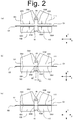
- Fig. 2 includes diagrams for explaining mainly the movement of the first holding part 11 (the first upper holder 111 and the first lower holder 112) and the second holding part 12 (the second upper holder 121 and the second lower holder 122) mainly along the Y direction.
- the state in Fig. 2(a) shows a position at which the opposed surfaces OS1 of the first upper holder 111 and the first lower holder 112 (the same applies to the second upper holder 121 and the second lower holder 122) are separated farthest from each other in the Y direction.
- a position will be referred to as a Y direction separated position.
- This state also shows a position at which the opposed surfaces OS2 of the first holding part 11 and the second holding part 12 are separated farthest from each other in the X direction.
- such a position will be referred to as an X direction separated position.
- Fig. 2(b) shows a state in which the first upper holder 111 and the first lower holder 112 have moved to a position at which the opposed surfaces OS1 thereof abut against each other from the state shown in Fig. 2(a) .
- the first holding part 11 sandwiches (the wider surfaces WS of) the first rectangular conductor by the first upper holder 111 and the first lower holder 112
- the second holding part 12 sandwiches (the wider surfaces WS of) the second rectangular conductor by the second upper holder 121 and the second lower holder 122.
- the first holding part 11 sandwiches the first rectangular conductor C1 so that the first rectangular conductor C1 projects in the direction of the second holding part 12 from the opposed surfaces OS2 along the Y direction.
- the second holding part 12 sandwiches the second rectangular conductor C2 so that the second rectangular conductor C2 projects in the direction of the first holding part 11 from the opposed surfaces OS2 along the Y direction.
- a projected amount A1 of the first rectangular conductor C1 from the first holding part 11 and a projected amount A2 of the second rectangular conductor C2 from the second holding part 12 will be described later.
- the position at which the opposed surfaces OS1 of the first upper holder 111 and the first lower holder 112 (the second upper holder 121 and the second lower holder 122) abut against each other will be referred to as a sandwiching position.
- the first upper holder 111 and the first lower holder 112 (the second upper holder 121 and the second lower holder 122) can move between the sandwiching position and the Y direction separated position.
- a sandwiching released position (in the Y direction) is present between the sandwiching position and the Y direction separated position as shown in Fig. 2(c) .
- the released position in the Y direction refers to a position at which the first upper holder 111 and the first lower holder 112 (the second upper holder 121 and the second lower holder 122) are separated away from each other by a smaller distance than the Y direction separated position.
- Y direction released position in Fig. 2(c) can transition to the state shown in Fig. 2(b) by moving the first upper holder 111 and first lower holder 112 (the second upper holder 121 and the second lower holder 122) to the position at which the opposed surfaces OS1 thereof abut against each other.
- Fig. 3 includes diagrams for mainly explaining the movement of the first holding part 11 and the second holding part 12 along the X direction.
- Fig. 3(a) shows a position resulting from moving the first holding part 11 and the second holding part 12 along the X direction from the state shown in Fig. 2(b) so that the opposed surfaces OS2 are closest to each other.
- a close position such a position will be referred to as a close position.
- the first holding part 11 and the second holding part 12 can move between the X direction separated position shown in Fig. 2 and the close position shown in Fig. 3(a) .
- the first holding part 11 and the second holding part 12 never abut against each other even at the close position.
- the first holding part 11 sandwiches the first rectangular conductor C1 so that the first rectangular conductor C1 projects by the projected amount A
- the second holding part 12 sandwiches the second rectangular conductor C2 so that the second rectangular conductor C2 projects by the projected amount A2 ( Fig. 2(b) ).
- the first rectangular conductor C1 and the second rectangular conductor C2 are in a state abutted against (connected with) each other and further pressed against each other without causing the first holding part 11 and second holding part 12 to abut against each other.
- the projected amount A1 of the first rectangular conductor C1 from the first holding part 11 and the projected amount A2 of the second rectangular conductor C2 from the second holding part 12 are set to respective amounts slightly longer than lengths measured when the first rectangular conductor C1 and the second rectangular conductor C2 abut against each other with the first holding part 11 and the second holding part 12 being at the close position (amounts capable of being abutted and then pressed against each other).
- a pressing released position (in the X direction) is present between the close position and the X direction separated position ( Fig. 2(a) ) as shown in Fig. 3(b) .
- the released position in the X direction (hereinafter referred to as an X direction released position) refers to a position at which the first holding part 11 and the second holding part 12 are separated away from each other by a smaller distance than the X direction separated position.
- the first upper holder 111 and the first lower holder 112 When the first holding part 11 and the second holding part 12 are at the X direction released position, the first upper holder 111 and the first lower holder 112 also move to the Y direction released position so as to separate from each other and the second upper holder 121 and the first lower holder 112 also move to the Y direction released position so as to separate from each other.
- the rectangular conductor holding grooves 111A and 112A are rectangular grooves provided at positions distant inwardly from the end faces 111S and 112S of the first upper holder 111 and the first lower holder 112 by a distance d1 in the third direction (Z direction) and provided on the opposed surfaces OS1 of the first upper holder 111 and the first lower holder 112.
- the rectangular conductor holding grooves 111A and 112A need to hold (sandwich) the rectangular conductor reliably.
- their shapes are in conformity with the outer shape of the rectangular conductor, and a depth d2 of each groove is a depth smaller than or equal to a half of a thickness d3 of the sandwiched rectangular conductor (in this case, the first rectangular conductor C1).
- the depth of each of the rectangular conductor holding grooves 111A and 112A is smaller than the half of the thickness d2 of the rectangular conductor by about 5/100 mm.
- the rectangular conductor holding grooves 111A and 112A each include an anti-slip finished surface NS in order to sandwich (hold) the rectangular conductor reliably.
- the anti-slip finished surface NS is a surface with high frictional resistance or a high adsorptive surface, for example.
- the anti-slip finished surface NS may be, for example, a surface with increased frictional resistance due to fine uneven finish by sandblasting, for example, or a finished surface with projections and depressions in a shape of what is called a saw blade, which are formed so that frictional resistance in one direction becomes higher than frictional resistance in the other direction.
- the second upper holder 121 includes a rectangular conductor holding groove 121A provided at a position close to one end face (front face closer to an operator) in the third direction (the Z direction).
- the second upper holder 121 includes a rectangular conductor holding groove 122A provided at a position close to one end face in the third direction.
- the configurations of the rectangular conductor holding grooves 121A and 122A are similar to those of the rectangular conductor holding grooves 111A and 112A in the first holding part 11.
- the first holding part 11 sandwiches the first rectangular conductor C1 so that the first rectangular conductor C1 projects in the direction of the second holding part 12 from the opposed surfaces OS2 along the Y direction by the projected amount A1.
- the second holding part 12 sandwiches the second rectangular conductor C2 so that the second rectangular conductor C2 projects in the direction of the first holding part 11 from the opposed surfaces OS2 along the Y direction by the projected amount A2.
- the pressing parts 18 press the first upper holder 111 and the first lower holder 112 so that these holders abut against each other and press the second upper holder 121 and the second lower holder 122 so that these holders abut against each other. Consequently, the first rectangular conductor C1 and the second rectangular conductor C2 are brought into close contact with the rectangular conductor holding grooves 111A and 112A while being compressed in the plate thickness direction (having a reduced plate thickness) and thereby sandwiched by the first holding part 11 and the second holding part 12 (see Fig. 4 ).
- the first upper holder 111 and the first lower holder 112 in the first holding part 11, which are at the Y direction released position ( Fig. 2(c) ), may be moved to the sandwiching position ( Fig. 2(b) ) to cause the first upper holder 111 and the first lower holder 112 to sandwich the first rectangular conductor C1.
- the second upper holder 121 and the second lower holder 122 in the second holding part 12, which are at the Y direction released position ( Fig. 2(c) may be moved to the sandwiching position ( Fig. 2(b) ) to cause the second upper holder 121 and the second lower holder 122 to sandwich the second rectangular conductor C2.
- the pressing parts 18 also press the first upper holder 111 and the first lower holder 112 so that these holders abut against each other and press the second upper holder 121 and the second lower holder 122 so that these holders abut against each other. Consequently, the first rectangular conductor C1 and the second rectangular conductor C2 are brought into close contact with the rectangular conductor holding grooves 111A and 112A in the holes while being compressed in the plate thickness direction (having a reduced plate thickness) and thereby sandwiched by the first holding part 11 and the second holding part 12 (see Fig. 4 ).
- the first holding part 11 and the second holding part 12 in the sandwiching state are moved along the X direction from the X direction separated position ( Fig. 2(a) ) to the close position ( Fig. 3(a) ) against the biasing force from the biasing members 15.
- the first rectangular conductor C1 projects from the first holding part 11
- the second rectangular conductor C2 projects from the second holding part 12.
- These projected amounts A1 and A2 are amounts slightly longer than lengths measured when opposing end faces in the strip longitudinal direction abut against each other with the first holding part 11 and the second holding part 12 being at the close position ( Fig. 3(a) .
- the opposing end faces of the first rectangular conductor C1 and the second rectangular conductor C2 first come into contact with (abut against) each other before (just before) moving to the close position. Thereafter, the first holding part 11 and the second holding part 12 are moved to the close position ( Fig. 3(a) ) by the drive part 13. This causes the abutting end faces of the first rectangular conductor C1 and the second rectangular conductor C2 to be butted and pressed against each other, and thus welded together. More specifically, by causing the end faces of the first rectangular conductor C1 and the second rectangular conductor C2 to be pressed against each other, stable oxide films formed on the end faces are removed, and such end faces are plastically deformed to expose surfaces in an active state.
- the faces in the active state are made close to each other with an interval therebetween smaller than or equal to 10 angstrom to cause atomic binding between those metals.
- cold pressure welding is performed.
- the first rectangular conductor C1 and the second rectangular conductor C2 after the pressure welding have compressed (shortened) lengths in the strip longitudinal direction by means of the cold pressure welding as compared to before the pressure welding.
- the shortened amounts are equal in the first rectangular conductor C1 and the second rectangular conductor C2.
- the length with the first rectangular conductor C1 before the pressure welding is defined as L01 and the length of the second rectangular conductor C2 before the pressure welding is defined as L02
- the length of the first rectangular conductor C1 is shortened to L01'
- the length of the second rectangular conductor C2 is shortened to L02' due to the pressure welding.
- the first holding part 11 and the second holding part 12 never come closer to each other after these parts are moved to the close position. Thus, the end faces of the first rectangular conductor C1 and the second rectangular conductor C2 are stopped from further being pressed against each other.
- the biasing members 15 exert the biasing force in the direction in which the first upper holder 111 and the first lower holder 112 (the same applies to the second upper holder 121 and the second lower holder 122) are separated away from each other.
- the present embodiment is configured so that in the pressure welding released state ( Fig. 3(b) ), the first holding part (the first upper holder 111 and the first lower holder 112) is moved in a direction away from the second holding part 12 along the X direction via the drive transmission part so as to return to a first X direction released position and the second holding part (the second upper holder 121 and the second lower holder 122) is moved in a direction away from the first holding part 11 along the X direction via the drive transmission part so as to return to a second X direction released position in addition to the biasing force from the biasing members 15.
- the movement restraining units 17 restrain the movement of the first rectangular conductor C1 and the second rectangular conductor C2 in the direction in which they are separated away from each other along the X direction.
- the first holding part 11 and the second holding part 12 in the pressure welding state, the pressure welding released state, or the sandwiching state are controlled so as to move along the X direction to the X direction separated position. Also, the first upper holder 111 and the first lower holder 112 are moved along the Y direction so as to move to the Y direction separated position and the second upper holder 121 and the second lower holder 122 are moved along the Y direction so as to move to the Y direction separated position ( Fig. 2(a) ).
- the cold pressure welding apparatus 10 of the present embodiment performs the cold pressure welding of the first rectangular conductor C1 and the second rectangular conductor C2 by repeating the sandwiching state, the pressure welding state, and the pressure welding released state.
- the first holding part 11 and the second holding part 12 are moved to the Y direction released position so as to release the sandwiching of the rectangular conductors and the first holding part 11 and the second holding part are moved to the X direction released position. Thereafter, by transitioning to the sandwiching state, the first holding part 11 holds the first rectangular conductor C1 so that the predetermined projected amount A1 is projected and the second holding part 12 holds the first rectangular conductor C2 so that the projected amount A2 is projected.
- the sandwiching state then transitions to the pressure welding state again. In this manner, the pressing step can be repeated a plurality of times for one welding portion.
- the X direction released position refers to a position allowing that the first holding part 11 can teach the first rectangular conductor C1 with the first rectangular conductor C1 projected by the projected amount A1 and a position allowing that the second holding part 12 can sandwich the second rectangular conductor C2 with the second rectangular conductor C2 projected by the projected amount A2.
- the X direction released position may not correspond to the positions that will cause the rectangular conductors to project by the projected amounts A1 and A2 when subsequently transitioning to the sandwiching state (without changing the positions).
- the rectangular conductors may be sandwiched after the first holding part 11 and the second holding part 12 are moved to the positions that will cause the rectangular conductors to project by the projected amounts A1 and A2, respectively, in the sandwiching state.
- the cold pressure welding apparatus 10 may further include, in addition to the movement restraining units 17, another movement restraining unit (fixing member 16) for restraining the first rectangular conductor C1 and the second rectangular conductor C2 from moving in the direction in which they are separated away from each other along the X direction and restraining the first rectangular conductor C1 and the second rectangular conductor C2 from moving along the Y direction.
- another movement restraining unit fixing member 16
- the fixing member 16 includes, as one example, two pairs of cylindrical projections 161 and 162 with an interval therebetween slightly larger than the plate thickness of non-plastically-deformed portions of the first rectangular conductor C1 and the second rectangular conductor C2 and smaller than the length of a welded portion CP in the plate thickness direction; and projections (or plates) 163 (each having a shape of a rectangular column, for example) having a pair of restraining surfaces 163A provided lateral to the both ends of the welded portion in the plate thickness direction.
- the first rectangular conductor C1 and the second rectangular conductor C2 can maintain the positions immediately after the pressure welding, thus increasing the stability of the welded surface CP. Therefore, the welded portion CP can be prevented from separating after the pressure welding along with the first holding part 11 and the second holding part 12.
- the first holding part 11 and the second holding part 12 may not stop at the X direction released position and the Y direction released position, although these parts pass through such positions.
- the first upper holder 111 and the first lower holder 112 (the same applies to the second upper holder 121 and the second lower holder 122) may move among the sandwiching position, the Y direction released position, and the Y direction separated position without stopping, and the first holding part 11 and the second holding part 12 may move among the close position, the X direction released position, and the X direction separated position without stopping.
- the cold pressure welding has been employed in the conventional art to weld round wires. According to the cold pressure welding apparatus 10 of the above-described present embodiment, however, the cold pressure welding of rectangular conductors can be performed excellently and stably.
- Fig. 5 includes top views illustrating wider surfaces WS of the rectangular conductors C.
- the rectangular conductor C has a linear shape ( Fig. 5(a) ) or at least one bent portion ( Figs. 5(b) to 5(e) ).
- the rectangular conductors C are a plurality of strip-shaped rectangular conductors capable of having a helical shape when continuously joined together. These will be hereinafter referred to as coil pieces. Coil pieces having bent portions are bent in the same direction in the strip longitudinal direction so that such coil pieces have a helical shape when continuously joined together. Moreover, for coil pieces having bent portions, it is desirable that such bent portions preferably have at least one non-curved (for example, generally right-angle) shape.
- a helical structure formed by continuously joining (connecting) a plurality of coil pieces (rectangular conductors) together, in a state before being finished as a coil (helical structure to be finally obtained) is also referred to as a coil piece.
- the coil pieces (rectangular conductors) in the following description include: a coil piece as the smallest unit, which has a linear shape or one to four bent portion(s) in the same direction(s) in the strip longitudinal directions; and a coil piece formed by connecting a plurality of the coil pieces as the smallest unit to form a helical structure having one or more turns of a coil (helical structure to be finally obtained).
- the coil piece as the smallest unit will be referred to as a unit coil piece; a coil piece, which is formed by connecting a plurality of unit coil pieces together, in a state before being finally obtained as a coil (helical structure to be finally obtained) will be referred to as a welded coil piece; and a helical structure to be finally obtained (in a finished state) will be referred to as a coil.
- the plurality of coil pieces have approximately the same shapes and areas of their cross sections perpendicular to the strip longitudinal direction.
- a unit coil piece C0 is formed, as one example, in a shape having a linear shape or a generally right-angle non-curved bent portion (corner portion) by the punching of a copper plate (for example, a thickness of 1 mm). More specifically, the unit coil piece C0, when the wider surface WS thereof is viewed from the above, has on a straight line with no bent portions (I-shape) ( Fig. 5(a) ), an L-shape with a single bent portion ( Fig. 5(b) ), a U-shape (a shape of Japanese katakana "ko") having two bent portions ( Fig.
- a generally C-shape having three bent portions Fig. 5(d)
- a C-shape generally O-shape (generally a shape of Japanese katakana "ro")) having four bent portions and bent in the same direction ( Fig. 5(e) .
- the bent portions (corner portions) thereof all have generally right-angle shapes.
- a plurality of coil pieces are configured such that a prepared length L0, which is equal to the total distance of the coil pieces in the strip longitudinal direction, is longer than a finished length of the helical structure to be finally obtained (coil) in a helical longitudinal direction by a margin.
- the margin is set to a total shortened distance corresponding to an amount shortened by pressing when all of the plurality of coil pieces are cold pressure welded.
- the coil manufacturing apparatus 20 of the present embodiment is an application example of the above-described cold pressure welding apparatus 10, the same structures as those of the cold pressure welding apparatus 10 will be denoted by the same reference numerals and redundant description will be omitted. Structures preferably used in the coil manufacturing apparatus 20 will be mainly described in the following description.
- the end faces of the plurality of rectangular conductors (coil pieces) are cold pressure welded together while being pressed against each other along the strip longitudinal direction and thus shortening their distances in the strip longitudinal direction.
- the total shortened distance, corresponding to the amount shortened by cold pressure welding all of the plurality of rectangular conductors (coil pieces) together, is set to the margin. In this manner, the coil manufacturing apparatus 20 forms the helical structure.
- the coil manufacturing apparatus of the present embodiment As the number of times for the addition of a coil piece (the number of times for welding) increases, the length of the coil piece (welded coil piece) held by the first holding part 11 or the second holding part 12 increases.
- the first holding part 11 and the second holding part 12 thus have a configuration preferably used when manufacturing coils.
- one end faces (indicated by circles) of two unit coil pieces C01 and C02 are connected together to form a welded coil piece CC1 as shown in Fig. 6(b) in the first cold pressure welding.
- one end face of the welded coil piece CC1 is cold pressure welded with a unit coil piece C03 to form a welded coil piece CC2 ( Fig. 6(c) ).
- one end face of the welded coil piece CC2 (any one of the non-welded end faces of the unit coil pieces C01, C02, and C03) is cold pressure welded with a unit coil piece C04 to finish the coil 50 ( Fig. 6(d) ).
- the first holding part 11 or the second holding part 12 holds a bent (in this case, U-shaped (Japanese katakana "ko"-shaped)) coil piece, and the welded coil piece CC1, CC2 ... having a sequentially lengthened helical structure is present near the first holding part 11 or the second holding part 12.
- the first holding part 11 and the second holding part 12 thus need to have a configuration to avoid interference with such a coil piece.
- Fig. 7 includes diagrams for explaining a configuration of the first holding part 11.
- Fig. 7(a) is a diagram showing a state in which the single unit coil piece C0 is held by the first holding part 11 (a first upper holder 111 and a first lower holder 112) when opposed surfaces OS2 with respect to the second holding part 12 are viewed from the front.
- Fig. 7(b) is a front view of the finished coil 50 as viewed from the direction of the axial center of its helical structure.
- the coil piece in Fig. 7(a) corresponds to a cross-sectional view taken along line B-B in Fig. 7(b) .
- Fig. 7(c) is a front view (a cross-sectional view taken along line A-A in Fig. 7(a) ) of the first holding part 11.
- one end face of the first holding part 11 when U-shaped (Japanese katakana "ko"-shaped) coil pieces are connected together, one end face of the first holding part 11, specifically, a holder end face that is configured by one end face 111S of the first upper holder 111 and one end face 112S of the first lower holder 112, which is coplanar with the end face 111S, and that is perpendicular to the opposed surfaces OS2, is positioned in the internal space of the helical structure (including a space to be the internal space of the helical structure) (hereinafter, such an end face will be referred to as a helix internal end face IS).
- the helical portion end face IS refers to the front face of the first holding part 11 closer to an operator, for example.
- rectangular conductor holding grooves 111A and 112A in the first holding part 11 need to be provided at appropriate positions in order to avoid the interference between the first holding part 11 and the coil piece.
- a distance d1 from the helix internal end face IS to the closest end of the rectangular conductor holding grooves 111A and 112A (the upper end in Fig. 7(a) ) is defined to be smaller than a distance D1 of the internal space of the helical structure (coil 50) along a third direction (a Z direction in the figure: the strip width direction of the coil piece to be cold pressure welded).
- a length d4 ( Fig. 7(c) ) in the X direction of the first holding part 11 is defined to be smaller than a distance D2 ( Fig. 7(b) in the internal space of the helical structure (coil 50) along the X direction.
- Fig. 8 is a diagram corresponding to (viewed from the same direction) Fig. 7(a) and showing a state in which a welded coil piece CC is formed.
- the welded coil piece CC is formed on one side of the first holding part 11 (the same applies to the second holding part 12), i.e., on the first lower holder 112 side in this case.
- the coil piece (in this case, the welded coil piece CC) is cold pressure welded with the coil piece held by the second holding part 12 while elastically deforming and/or plastically deforming a portion of the coil piece excluding the vicinity of the end face to be cold pressure welded so as to expand in the helical traveling direction (direction along the Y direction) of the helical structure.
- a deformed amount D3 of the elastic deformation and/or plastic deformation of the coil piece (in this case, the welded coil piece CC) in the helical traveling direction is set to an amount to avoid the interference between the first holding part 11 and the coil piece.
- a length (thickness) d5, along the Y direction, of the holder of the first holding part 11 on the side where the welded coil piece is being formed is defined to be smaller than the deformed amount D3 allowed for the elastic deformation and/or plastic deformation of the coil piece (in this case, the welded coil piece CC) in the helical traveling direction.
- the first lower holder 112 is provided with an interference avoidance space ES (see also Fig. 4 ) on the front side in the helical traveling direction of the helical structure (in this case, on the lower side in the thickness direction of the coil piece being welded; on the front side in the Z direction (operator's side)).
- the interference avoidance space ES is a space capable of accommodating part of the welded coil piece CC.
- the provision of the interference avoidance space ES allows for the avoidance of the interference between part of the welded coil piece CC being connected and the holding part (in this case, the first lower holder 112).
- the first lower holder 112 has an L-shape as viewed from the side thereof in Figs. 8 and 4(a)
- the first lower holder 112 may have a flat plate shape with the thickness d5 (see Fig. 8 ). In such a case, a space under the first lower holder 112 serves as the interference avoidance space ES.
- the welded portion CP is provided not in the bent portion (corner portion) but in a linear portion.
- pressure welding is performed by utilizing the linear portion of the coil piece. Consequently, the form accuracy of the bent portion can be improved, and the corner portion shaped at a right angle (generally right angle) by the punching can be maintained as it is, for example.
- the prepared length L0 corresponding to their total distance in the strip longitudinal direction, equals L01 + L02 + L03 + L04.
- the length L01 of the unit coil piece C01 in the strip longitudinal direction is compressed to L01' (the shortened (compressed) amount is a length corresponding to a distance S1 from the center of the welded portion CP) and the length L02 of the unit coil piece C02 in the strip longitudinal direction is compressed to L2' ((the shortened (compressed) amount is a length corresponding to a distance S2 from the center of the welded portion CP) by the pressing.
- a welded coil piece CC1 (with a length LC1) is thus formed ( Fig. 9(b) ).
- the unit coil piece C04 When an end face of the welded coil piece CC2 (the non-welded end face of the unit coil piece C01, C02, or C03) is further cold pressure welded with the unit coil piece C04, the unit coil piece C04 is compressed to L04' (the shortened (compressed) amount is a length corresponding to a distance S5 from the center of the welded portion CP) and the welded coil piece CC2 is compressed to LC2' ((the shortened (compressed) amount is a length corresponding to a distance S6 from the center of the welded portion CP) by the pressing.
- the coil 50 (helical structure) with the finished length (length from a starting point ST to an end point ET) L in the helical longitudinal direction is thus formed ( Fig.
- the coil manufacturing method of the present embodiment will be described again in chronological order.
- the lengths L01 to L04 of the unit coil pieces are set and the compressed amounts S1 to S6 caused by the cold pressure welding are set so that the total shortened distance S is equal to the margin M.
- a burr is generated in the welded portion by the pressing.
- a process of removing the burr is performed after the cold pressure welding.
- the coil piece (the welded coil piece CC1) is cold pressure welded with another coil piece (the unit coil piece C03) while elastically deforming and/or plastically deforming a portion of the coil piece (the welded coil piece CC1) excluding the vicinity of the end face to be cold pressure welded (the non-welded end face of the unit coil piece C01 or the unit coil piece C02) in the helical traveling direction of the helical structure to be finally obtained.
- the deformed amount of the elastic deformation and/or plastic deformation of the welded coil piece CC1 in the helical traveling direction is set to an amount to avoid the interference between the first holding part 11 and the second holding part 12, which hold the coil pieces during the cold pressure welding, and the welded coil piece CC1. Such a deformed amount is similarly employed in the following cold pressure welding.
- a coil piece is similarly added. More specifically, an end face of the welded coil piece CC1 (non-welded end face of the unit coil piece C01 or C02) and the unit coil piece C03 are connected together by means of the cold pressure welding while being pressed against each other by the compressed amounts S3 and S4 to form the welded coil piece CC2. Thereafter, the burr in the welding region is removed.
- the finished helical structure 50' is shaped by press working, for example. More specifically, the helical structure is elastically deformed and/or plastically deformed in the helical traveling direction in order to avoid interference with the first holding part 11 and the second holding part 12 during the cold pressure welding. Such a helical structure thus has an unnecessary and non-uniform distance (space) between adjacent helical turns. The helical structure is thus elastically deformed and/or plastically deformed in the helical traveling direction so as to compress such spaces. In this manner, the helical turns are brought closer to (brought into intimate contact with) one another as much as possible ( Fig. 10(c) ).
- the shaped helical structure is dipped into a liquid insulating resin so as to be integrally coated with the insulating resin.
- the shaped helical structure may be sprayed with a liquid insulating resin so as to be integrally coated with the insulating resin.
- the insulating resin is stretched in the outer peripheral region of the curved portion in such winding, resulting in reduction in the coating thickness thereof and thus leading to deterioration in the pressure resistance thereof.
- Fig. 11(a) is a top view illustrating a connection example when L-shaped coil pieces are used.
- a case where four L-shaped coil pieces C0 are used to form a connected coil piece for one turn is illustrated here.
- the respective coil pieces are configured such that a prepared length L0 of these coil pieces, corresponding to their total distance in the strip longitudinal direction, is also set to be longer than a finished length L of a helical structure to be finally obtained (coil) in the helical longitudinal direction by a margin M.
- the margin M is set to a total shortened distance S corresponding to an amount shortened by pressing when all of the plurality of coil pieces are cold pressure welded together.
- the coil connected piece for one turn may not be configured by the same shape (L-shape).
- L-shaped, I-shaped (linear), and U-shaped (Japanese katakana "ko"-shaped) coil pieces may be combined with one another to form a coil connected piece for one turn.
- Fig. 11(b) is a top view illustrating a connection example in which a C-shaped coil piece C0 and an I-shaped coil piece C1 are combined with each other.
- the respective coil pieces are configured such that a prepared length L0 of these coil pieces, corresponding to their total distance in the strip longitudinal direction, is also set to be longer than a finished length L of a helical structure to be finally obtained (coil) in the helical longitudinal direction by a margin M.
- the margin M is set to a total shortened distance S corresponding to an amount shortened by pressing when all of the plurality of coil pieces are cold pressure welded together.
- a generally C-shaped coil piece having three corner portions may be combined with an L-shaped coil piece to form a coil connected piece for one turn.
- coil pieces constituting a first turn of a helical structure may have a combination different from coil pieces constituting a second turn of the helical structure.
- Fig. 11(c) is a development view when a U-shaped (Japanese katakana "ko"-shaped) coil piece C0 having two corner portions and a coil piece for one turn of a helical structure to be finally obtained (O-shaped (Japanese katakana "ro"-shaped) coil piece) C1 are combined with each other to form a welded coil piece.
- Chain double-dashed lines at both ends of the coil piece in Fig. 11(c) indicate the finished ends of the finished coil. This example will be described assuming that no finished ends change (the positions of the finished ends do not move in the right or left direction in the figure).
- the O-shaped coil piece C1 is cut in its welded portions.
- the U-shaped coil piece C0 and one end of the O-shaped coil piece C1 are cold pressure welded together, the U-shaped coil piece C0 is compressed by a compressed amount S0 and the O-shaped coil piece C1 is compressed by a compressed amount S1.
- a helical structure can be formed by repeating such a step.
- the welded portion CP is formed at substantially the same position (overlapping position) along the axial center of the helical structure in each turn of the helical structure as shown in the figure.
- a connected portion CP is formed at a position displaced by a predetermined amount along the axial center (broken line) of the helical structure in each turn of the helical structure.
- Fig. 12 includes diagrams illustrating a coil manufacturing apparatus and a coil manufacturing method according to a modified example.
- Fig. 12(a) is a schematic diagram of a coil manufacturing apparatus 20'.
- Fig. 12(b) is a side view corresponding to Fig. 10(c) , illustrating a coil 50 manufactured by the coil manufacturing apparatus 20'.
- Fig. 12(c) is a perspective view of the coil 50.
- the coil manufacturing apparatus 20' may include a plurality of holding units 22 each configured by the above-described first holding part 11 and second holding part 12.
- the plurality of holding units 22 (22A to 22E) may have the first holding parts 11 and the second holding parts 12 in which widths W (widths along the Z direction; widths of rectangular conductors in a strip width direction BS) of rectangular conductor holding grooves 111A, 112A, 121A, and 122A are different from one another (sequentially increased (or decreased)).
- a helical structure having coil turns with respectively different lengths can be formed by performing cold pressure welding in a different holding unit 22 for each turn of the helical structure while moving the helical structure sequentially among the plurality of holding units 22.
- the coil 50 Figs. 12(b) and 12(c) having an outer shape of a truncated quadrangular pyramid can be formed by connecting the coil pieces together by the cold pressure welding while sequentially moving the coil pieces among the plurality of holding units 22.
- a plurality of holding units 22 each having a different depth d3 of the rectangular conductor holding grooves 111A, 112A, 121A, and 122A may be employed.
- the plate thicknesses of the turns of the helical structure constituting the coil 50 can be made different from one another.
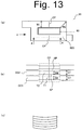
- Fig. 13(a) is a front view of the coil as viewed from the axial center direction of the helical structure.
- Fig. 13(b) is a cross-sectional view taken along line A-A in Fig. 13(a).
- Fig. 13(c) is a side view of Fig. 13(a) as viewed from the V direction.
- the coil 50 of the present embodiment is a helical structure obtained by continuously joining strip-shaped rectangular conductors (coil pieces) together in a helical shape. As shown in Fig. 13(a) , the coil 50 includes non-curved corner portions (generally right-angle corner portions) 50C on the inner and outer peripheral sides of the helical structure.
- the coil 50 in this case has been manufactured with the above-described coil manufacturing apparatus and coil manufacturing method by way of example.
- a shape for one turn of the helical structure of the coil can be formed by punching according to the coil 50 of the present embodiment.
- a coil having a desired form as viewed from the front can be formed.
- the coil 50 having a shape in conformity with the shape of the stator coil and capable of being positioned closer to the stator coil as much as possible at least the inner peripheral corner portion 50C has a right-angle or generally right-angle shape
- This can minimize the space formed between the coil 50 and a stator core 60 (indicated by a broken line in Fig. 13(a) ) unlike the wound coil.
- the length of the space (distance from the inner periphery of the coil 50 to the stator core 60) per one side of the coil 50 can be reduced to 0.5 mm to 1.0 mm. This can improve the heat dissipation performance.
- the insulating resin can coat the entire coil 50 with increased uniformity, deterioration in pressure resistance due to variations in the film thickness of the insulating resin can be prevented from occurring.
- a width perpendicular to the helical traveling direction of the helical structure (a width W1 of the coil piece in the strip width direction) changes to a broadened width W2 in the corner portion. This can also reduce coil resistance.
- the cold pressure welding is atomic binding between metals.
- the connected portions thereof are welded together reliably to an invisible level.
- the stability of the connected portions can be enhanced significantly as compared to a configuration in which flat surfaces of coils for one turn (or less) are connected together with an adhesive material (for example, with a fixing material or by brazing).
- part of the first helical turn of the helical structure (for example, the first turn by a welded coil piece CC1) is provided with a first thin portion T1 having a plate thickness D8 thinner than a plate thickness D7 of the other part of the rectangular conductor (coil piece).
- part of the second turn (for example, the second turn by a welded coil piece CC2) continuous with the first turn is provided with a second thin portion T2 having the plate thickness D8 that is thinner than the other part and the plate thickness D7 of the rectangular conductor (coil piece).
- the total depth of the rectangular conductor holding grooves 111A and 112A (the same applies to the total depth of the rectangular conductor holding grooves 121A and 122A) is smaller than the plate thickness D7 of the coil piece.
- the sandwiched portions are compressed in the plate thickness direction so as to have the thickness (D8) approximately the same as the total depth of the rectangular conductor holding grooves 121A and 122A.
- the portions sandwiched by the first holding part 11 and the second holding part 12 correspond to the first thin portion T1 and the second thin portion T2.
- the first thin portion T1 and the second thin portion T2 are formed corresponding to the welded portions CP in the cold pressure welding.
- the first thin portion T1 is provided at two positions in the first turn
- the second thin portion T2 is provided at two positions in the second turn.
- U-shaped unit coil pieces all have the same length
- the first thin portion T1 and the second thin portion T2 are provided at overlapping positions in the axial center direction of the helical structure as indicated by a broken-line rectangle.
- the first thin portion T1 and the second thin portion T2 which are formed corresponding to the welded portions CP in the cold pressure welding, are formed at positions displaced in opposite directions in the first turn and the second turn so as to correspond to their connected portions CP (for the O-shaped coil piece, only one thin portion is formed per one turn).
- All turns of the coil 50, together constituting the helical structure, are integrally coated with an insulating resin. This can enhance the degree of adhesion among the turns of the helical structure.
- a gap SP of the coil piece is formed between the first thin portion T1 and the second thin portion T2, part of the insulating resin is embedded also in the gap SP.
- the insulating resin enters into the gap SP since the helical structure is dipped into the liquid insulating resin after being finished (and after being shaped if necessary) as described in the above-described manufacturing method. This can further enhance the degree of adhesion among the turns of the helical structure.
- the coil 50 may be shaped to have a depressed form or a protruded form in the axial center direction of the helical structure (the radial direction of the stator core), i.e., shaped to have a curved form in which the inner peripheral end thereof is not coplanar with the outer peripheral end thereof as shown in Fig. 13(c) .
- Fig. 14 is a graph comparing the coil 50 of the present embodiment with a coil formed by winding a round wire (round wire coil) for the measured heating values thereof.
- the heating values (temperatures) of the round wire coil and the coil 50 of the present embodiment were measured over time at 5 V and 20 A.
- the temperature of the round wire coil rose sharply to 28.5°C in the first 10 seconds and to 42°C in the first 30 seconds. Since the temperature rose to 73°C in 90 seconds from the start, the experiment was ceased.
- the temperature of the coil 50 (20 A) of the present embodiment rose gently to 21.1°C in the first 10 seconds and to 21.5°C in the first 30 seconds. The temperature reached saturation at 32.4°C after a lapse of 1,530 seconds from the start.
- the temperature of the coil of the present embodiment (coil in which the inner peripheral side thereof has a generally right-angle shape (coil with the right-angle inner periphery)) 50 hardly rises above a temperature close to the ordinary temperature (for example, 40°C to 50°C) even during the operation thereof.
- the coil 50 of the present embodiment has significantly high heat dissipation performance. Such high heat dissipation performance can significantly reduce coil resistance as compared to the conventional coil.
- a width W3 of the starting edge and end edge of the helical structure of the coil 50 may be set larger than the width W1 of the coil 50 in the strip width direction. This can reduce coil resistance at the starting edge and the end edge as with the corner portions.
- the coil 50 having the right-angle inner periphery which is formed by repeatedly welding end faces of coil pieces together by means of cold pressure welding, has been described in the present embodiment.
- the present invention is not limited thereto.
- the end faces of the coil pieces may be welded according to another welding method.
- Specific examples may include various connection methods such as ultrasonic welding (high-frequency welding), electric welding, and brazing.
- FIG. 15 an attachment example of the coil 50 of the present embodiment to a stator core will be described.
- Fig. 15(a) is a side view of the coil 50 and cassettes 51A and 51B.
- Fig. 15(b) is a top view of Fig. 15(a).
- Fig. 15(c) is a side view top view illustrating an attachment example to the stator core 60.
- the coil 50 of the helix axis present embodiment is formed by being shaped in conformity with the outer shape of the stator core as shown in Fig. 13(c) and then being integrally coated with the insulating resin. The thus obtained coil 50 is attached to the stator core afterward.
- the two cassettes 51A and 51B having flanges 52A and 52B on one side in the axial center direction of the helical structure of the coil 50 are prepared as shown in Fig. 15(a) .
- the coil 50 is introduced from the side of one cassette 51A where no flange 52A is formed.
- the other cassette 51B is placed over the cassette 51A and these cassettes are engaged with each other.
- the thus obtained coil 50 having the cassettes is inserted into the stator core 60.
- Notches or engagement parts 53 to be fitted together are provided in the cassettes 51A and 51B in the top view shown in Fig. 15(b) .
- the coil 50 may be attached to one cassette 51C having a flange 52C only on one side in the axial center direction of the helical structure and then installed in the stator core 60 as shown in Fig. 15(c) .
- the stator core 60 may be provided with a notch 61, and a retaining ring 62 for covering a portion above the coil 50 having the cassette and the notch 61 of the stator core 60 may be fitted together after the coil 50 having the cassette is attached to the stator core 60 in order to prevent the coil 50 from coming off from the stator core 60 (or from causing unnecessary movement (vibration)) due to centrifugal force during its operation.
- Fig. 16 includes side views illustrating the coil 50 of the present embodiment.
- Fig. 16(a) is a side view of the coil 50 as viewed from its shorter side
- Fig. 16(b) is a side view of the coil 50 as viewed from its longer side according to one example.
- Fig. 16(c) is a side view of the coil 50 as viewed from its shorter side
- Fig. 16(d) is a side view of the coil 50 as viewed from its longer side according to another example.
- Fig. 16(e) is a side view of the coil 50 as viewed from its shorter side according to still another example.
- Fig. 17 shows a modified example of Figs.
- Figs. 16(b) and 16(c) are external perspective views.
- Figs. 17(b) and 17(d) are side views on arrows in Figs. 17(a) and 17(c) , respectively.
- the unit coil piece is gradually deformed along the helical traveling direction for one turn from the first helical turn TC1 to the second helical turn TC2 so as to absorb the thickness of the unit coil piece as shown in Figs. 16(a) and 16(b) . Such a step is repeated for each turn.
- each coil piece is connected to the next coil piece while being slightly tilted to form the helical structure as shown in Figs. 16(a) and 16(b) .
- a shorter-side side surface ( Fig. 16(a) ) and a longer-side side surface ( Fig. 16(b) ) of the coil 50 are illustrated here, all of the four side surfaces of the coil 50 are tilted similarly.
- the coil 50 of the present embodiment is not limited to the above-described structure. Helical structures as shown in Figs. 16(c) to 16(e) may be employed.
- part of the first helical turn TC1 of the helical structure is deformed to create a level difference B corresponding to the thickness of the coil piece along the helical traveling direction and part of the second helical turn TC2 is deformed to have the level difference B corresponding to the thickness of the coil piece along the helical traveling direction as shown in Fig. 16(b) .
- Such a step is repeated to form a helical structure.
- An area where the level differences B are created is present only on one side surface (for example, one of the shorter-side side surfaces) of the coil 50.
- the level differences B are created in the same area, i.e., the level difference B in the second turn is created on the level difference B in the first turn.
- the thickness of the coil piece is absorbed by the level difference B created only on one side surface as described above.
- the coil pieces are layered generally horizontally without being tilted for the other three side surfaces.
- Such a configuration can make the outermost peripheral surfaces of the coil flat without a starting edge SE and an end edge EE of the coil 50 being projected. More specifically, in the helical structure shown in Figs. 16(a) and 16(b) , a surface (the lower end face in the figure) of the coil 50 including the starting edge SE is not coplanar with a coil surface SF11' formed by making a loop from a coil surface SF12' of the starting edge SE and positioned on a side opposite to the coil surface SF12', creating a level difference therebetween as shown in Fig. 16(a) .
- a surface (the upper end face in the figure) of the coil 50 including the end edge EE is not coplanar with a coil surface SF22' positioned on a side opposite to a coil surface SF21' of the end edge EE, creating a level difference therebetween.
- Such level differences cause no significant problem when the thickness of the coil piece is relatively thin.
- spaces corresponding to such level differences need to be provided when the coil is set to the cassettes 51A and 51B as shown in Fig. 15 . Additionally, the thus created gaps may cause a problem such as the backlash of the coil 50.
- a surface (the lower end face in the figure) of the coil 50 including the starting edge SE is provided (generally) coplanar with a coil surface SF11 formed by making a loop from a coil surface SF12 of the starting edge SE and positioned on a side opposite to the coil surface SF12
- a surface (the upper end face in the figure) of the coil 50 including the end edge EE is provided (generally) coplanar with a coil surface SF22 positioned on a side opposite to a coil surface SF21 of the end edge EE according to the helical structure shown in Figs. 16(c) and 16(d) .
- This can reduce the size of the outer shape of the coil 50 and can enhance the degree of adhesion to the cassettes 51A and 51B.
- Fig. 16(e) shows another example having a helical structure similar to that shown in Figs. 16(c) and 16(d) but having a different coil piece shape.
- the coil piece has a (generally) square cross section having a width W in the strip width direction BS and a thickness d2 approximately equal to each other as shown in Fig. 16(e) .
- the thickness d2 is large relative to the width W as in this example, it is more preferred to employ the helical structure in which the level differences B are provided on one side surface of the coil 50 as shown in Fig. 16(e) .
- Fig. 17 includes diagrams illustrating another example of the present embodiment.
- all of the coil pieces constituting the coil 50 may each have a different width W in the strip width direction BS and a different thickness d2.
- coil pieces, each having a gradually increased width W (WA, WB ...) and a gradually decreased thickness d2 from a starting edge SE toward an end edge EE are connected together.
- widths W of coil pieces may vary (change) or only the thicknesses d2 of coil pieces may vary (change) without being limited to the above-described example.
- the coil 50 in a shape of a desired truncated quadrangular pyramid can be manufactured.
- a difference between the thicknesses d2 of the coil pieces in the starting edge SE and the end edge EE causes a difference between the level difference values of the outermost peripheral (upper outermost peripheral and lower outermost peripheral in the figure) coil surfaces.
- This increases the size of the outer shape of the coil 50 and makes the shape of the coil 50 non-uniform (asymmetric). Therefore, an extra space further needs to be provided in the cassettes 51A and 51B.
- the outermost peripheral coil surfaces can be made (generally) flat (coil surfaces SF11 and SF12 can be made coplanar with each other and coil surfaces SF21 and SF22 can be made coplanar with each other) even when the thicknesses d2 of the coil pieces vary.
- a significant size reduction in the outer shape of the coil 50 can be achieved and the trouble when the coil 50 is attached to the cassettes 51A and 51B can be prevented from occurring.
- the level differences B may be provided on a longer-side side surface of the coil 50.
- the positions where the level differences B are provided can be appropriately selected depending on the shapes of the drawn starting edge SE and end edge EE.
- the present invention can be configured by various embodiments without being limited to the above-described embodiment.
- the bent portion of a coil piece may have a curved shape.
- One of the coil piece is not limited to a coil piece formed by punching a copper plate.
- One of the coil piece may be formed by arranging a plurality of thin rectangular conductors (for example, rectangular conductors each having a square cross section in the strip longitudinal direction as shown in Fig. 16(e) ) in parallel.
- a coil may be configured partially by a coil piece formed by punching a copper plate and partially by a coil piece formed by arranging thin rectangular conductors in parallel.
- the present invention can be employed, for example, when a coil apparatus using a rectangular coil is manufactured.
Landscapes
- Engineering & Computer Science (AREA)
- Power Engineering (AREA)
- Manufacturing & Machinery (AREA)
- Mechanical Engineering (AREA)
- Manufacture Of Motors, Generators (AREA)
- Pressure Welding/Diffusion-Bonding (AREA)
- Manufacturing Cores, Coils, And Magnets (AREA)
Priority Applications (1)
| Application Number | Priority Date | Filing Date | Title |
|---|---|---|---|
| EP23156778.5A EP4230337A3 (de) | 2013-12-18 | 2014-12-18 | Vorrichtung zur herstellung einer spule und spulenherstellungsverfahren |
Applications Claiming Priority (4)
| Application Number | Priority Date | Filing Date | Title |
|---|---|---|---|
| JP2013261581A JP5592554B1 (ja) | 2013-12-18 | 2013-12-18 | 冷間圧接装置、コイル製造装置、コイルおよびその製造方法 |
| JP2014252885A JP6505431B2 (ja) | 2013-12-18 | 2014-12-15 | コイルおよびその製造方法 |
| EP14870832.4A EP3085486B1 (de) | 2013-12-18 | 2014-12-18 | Kaltschweissvorrichtung |
| PCT/JP2014/083556 WO2015093562A1 (ja) | 2013-12-18 | 2014-12-18 | 冷間圧接装置、コイル製造装置、コイルおよびその製造方法 |
Related Parent Applications (2)
| Application Number | Title | Priority Date | Filing Date |
|---|---|---|---|
| EP14870832.4A Division-Into EP3085486B1 (de) | 2013-12-18 | 2014-12-18 | Kaltschweissvorrichtung |
| EP14870832.4A Division EP3085486B1 (de) | 2013-12-18 | 2014-12-18 | Kaltschweissvorrichtung |
Related Child Applications (1)
| Application Number | Title | Priority Date | Filing Date |
|---|---|---|---|
| EP23156778.5A Division EP4230337A3 (de) | 2013-12-18 | 2014-12-18 | Vorrichtung zur herstellung einer spule und spulenherstellungsverfahren |
Publications (2)
| Publication Number | Publication Date |
|---|---|
| EP3822017A2 true EP3822017A2 (de) | 2021-05-19 |
| EP3822017A3 EP3822017A3 (de) | 2021-07-07 |
Family
ID=51702034
Family Applications (4)
| Application Number | Title | Priority Date | Filing Date |
|---|---|---|---|
| EP20216266.5A Pending EP3822017A3 (de) | 2013-12-18 | 2014-12-18 | Kaltpressschweissvorrichtung, spulenherstellungsvorrichtung, spule und verfahren zur herstellung davon |
| EP18191373.2A Active EP3427885B1 (de) | 2013-12-18 | 2014-12-18 | Kaltpressschweissvorrichtung, spulenherstellungsvorrichtung, spule und verfahren zur herstellung davon |
| EP17185743.6A Active EP3263270B1 (de) | 2013-12-18 | 2014-12-18 | Kaltpressschweissvorrichtung, spulenherstellungsvorrichtung, spule und verfahren zur herstellung davon |
| EP14870832.4A Active EP3085486B1 (de) | 2013-12-18 | 2014-12-18 | Kaltschweissvorrichtung |
Family Applications After (3)
| Application Number | Title | Priority Date | Filing Date |
|---|---|---|---|
| EP18191373.2A Active EP3427885B1 (de) | 2013-12-18 | 2014-12-18 | Kaltpressschweissvorrichtung, spulenherstellungsvorrichtung, spule und verfahren zur herstellung davon |
| EP17185743.6A Active EP3263270B1 (de) | 2013-12-18 | 2014-12-18 | Kaltpressschweissvorrichtung, spulenherstellungsvorrichtung, spule und verfahren zur herstellung davon |
| EP14870832.4A Active EP3085486B1 (de) | 2013-12-18 | 2014-12-18 | Kaltschweissvorrichtung |
Country Status (4)
| Country | Link |
|---|---|
| US (3) | US10211710B2 (de) |
| EP (4) | EP3822017A3 (de) |
| JP (1) | JP5592554B1 (de) |
| CN (2) | CN109274223B (de) |
Cited By (1)
| Publication number | Priority date | Publication date | Assignee | Title |
|---|---|---|---|---|
| EP4230337A2 (de) | 2013-12-18 | 2023-08-23 | Aster Co., Ltd. | Vorrichtung zur herstellung einer spule und spulenherstellungsverfahren |
Families Citing this family (18)
| Publication number | Priority date | Publication date | Assignee | Title |
|---|---|---|---|---|
| JP5592554B1 (ja) | 2013-12-18 | 2014-09-17 | 武延 本郷 | 冷間圧接装置、コイル製造装置、コイルおよびその製造方法 |
| CN110178291A (zh) | 2017-01-18 | 2019-08-27 | 松下知识产权经营株式会社 | 电动机 |
| WO2018155221A1 (ja) | 2017-02-21 | 2018-08-30 | パナソニックIpマネジメント株式会社 | モータ |
| US11070103B2 (en) | 2017-02-21 | 2021-07-20 | Panasonic Intellectual Property Management Co., Ltd. | Motor |
| CN107755873A (zh) * | 2017-11-30 | 2018-03-06 | 西安启源机电装备有限公司 | 一种铅带冷压对焊装置 |
| JP6911740B2 (ja) * | 2017-12-15 | 2021-07-28 | トヨタ自動車株式会社 | コイル搬送装置 |
| JP7038407B2 (ja) | 2018-02-08 | 2022-03-18 | 株式会社アスター | コイルユニット、ステータ部材、ステータ、モータおよびこれらの製造方法 |
| CN117543916A (zh) | 2018-07-17 | 2024-02-09 | 株式会社阿斯特 | 线圈制造装置、线圈制造方法以及线圈制造系统 |
| CN110971040B (zh) * | 2018-09-28 | 2021-09-03 | 比亚迪股份有限公司 | 定子组件及具有该定子组件的电机 |
| IT201800020275A1 (it) * | 2018-12-20 | 2020-06-20 | Amx Automatrix S R L | Pressa di sinterizzazione per sinterizzare componenti elettronici su un substrato |
| JP7373827B2 (ja) | 2019-02-19 | 2023-11-06 | 株式会社アスター | コイル接合体およびコイル接合体の製造方法 |
| CN109822204B (zh) * | 2019-03-01 | 2022-02-08 | 西安斯瑞先进铜合金科技有限公司 | 一种采用冷压工艺焊接CuFe合金材料的焊接方法 |
| JP7417236B2 (ja) * | 2019-05-08 | 2024-01-18 | 株式会社アスター | ステータ部材、ステータおよびモータ |
| JP7430067B2 (ja) | 2020-01-30 | 2024-02-09 | 武延 本郷 | コイルの製造方法 |
| JP7497010B2 (ja) * | 2020-03-03 | 2024-06-10 | 株式会社アスター | コイルの製造方法およびコイル |
| DE102020209434A1 (de) * | 2020-07-27 | 2022-01-27 | Robert Bosch Gesellschaft mit beschränkter Haftung | Elektromotorvorrichtung, Elektromotor mit der Elektromotorvorrichtung und Verfahren zur Herstellung einer Statoreinheit einer Elektromotorvorrichtung |
| JP7525891B2 (ja) | 2020-11-09 | 2024-07-31 | 株式会社アスター | コイル、ステータおよびモータ |
| CN114523184B (zh) * | 2022-04-22 | 2022-08-16 | 南通大地电气股份有限公司 | 一种金属线材冷压焊接装置 |
Citations (3)
| Publication number | Priority date | Publication date | Assignee | Title |
|---|---|---|---|---|
| JP2005130676A (ja) | 2003-10-27 | 2005-05-19 | Fuji Heavy Ind Ltd | 電気機器用コイルの製造方法 |
| JP3881520B2 (ja) | 2001-01-24 | 2007-02-14 | 士郎 嶋原 | コイル装置 |
| EP3085486A1 (de) | 2013-12-18 | 2016-10-26 | Takenobu Hongo | Kaltschweissvorrichtung, spulenherstellungsvorrichtung, spule und herstellungsverfahren dafür |
Family Cites Families (71)
| Publication number | Priority date | Publication date | Assignee | Title |
|---|---|---|---|---|
| US2751724A (en) * | 1952-12-26 | 1956-06-26 | Smith Corp A O | Belt grinding apparatus |
| US2779954A (en) * | 1953-06-25 | 1957-02-05 | Utica Drop Forge & Tool Corp | Double action trimmer and surface preparation tool for solid phase bonding |
| GB892874A (en) * | 1960-10-28 | 1962-04-04 | Standard Telephones Cables Ltd | Improvements in or relating to cold pressure welding |
| NL142018B (nl) * | 1964-11-26 | 1974-04-16 | Philips Nv | Werkwijze tot het vervaardigen van een halfgeleidende inrichting en inrichting vervaardigd volgens de werkwijze. |
| GB1145265A (en) * | 1965-06-03 | 1969-03-12 | Eisler Paul | Methods of producing helicoids |
| US3768718A (en) * | 1968-10-11 | 1973-10-30 | Kelsey Hayes Co | Fine wire butt welder |
| JPS50139903A (de) * | 1974-04-30 | 1975-11-10 | ||
| US4078712A (en) * | 1975-01-21 | 1978-03-14 | Alforge Metals Corporation Limited | Welding of aluminum and magnesium alloys |
| US3992818A (en) * | 1975-11-20 | 1976-11-23 | Elektrogeno As | Apparatus for grinding and polishing a welded seam |
| DE2555697B2 (de) * | 1975-12-11 | 1978-08-03 | Dr. Eugen Duerrwaechter Doduco, 7530 Pforzheim | Verfahren zum Herstellen von Doppelkontaktnieten |
| DE2606235A1 (de) * | 1976-02-13 | 1977-08-18 | Siemens Ag | Vorrichtung zum stumpfen kaltpressschweissen von draehten oder baendern |
| US4029252A (en) * | 1976-05-17 | 1977-06-14 | General Electric Company | Apparatus for making a copper-aluminum transition joint |
| US4094453A (en) * | 1976-08-02 | 1978-06-13 | Alforge Metals Corporation, Limited | Method for pressure welding metal workpieces |
| JPS5816783A (ja) * | 1981-07-22 | 1983-01-31 | Toshiba Corp | 加圧圧接方法 |
| DE3143208C2 (de) * | 1981-10-30 | 1984-07-05 | Max-E. Dipl.-Ing. 7320 Göppingen Reeb | Identifizierungsanordnung in Form eines an einem Gegenstand anbringbaren etikettartigen Streifens und Verfahren zu deren Herstellung |
| JPS59199186A (ja) * | 1983-04-27 | 1984-11-12 | Toshiba Corp | 固相接合装置 |
| JPS59209046A (ja) * | 1983-05-13 | 1984-11-27 | Toshiba Corp | 界磁コイルの製造方法 |
| JPS59209045A (ja) * | 1983-05-13 | 1984-11-27 | Toshiba Corp | 界磁コイルの製造方法 |
| JPS6213281A (ja) * | 1985-07-12 | 1987-01-22 | Hitachi Ltd | 冷間接合装置 |
| JPS6240041A (ja) * | 1985-08-13 | 1987-02-21 | Toshiba Corp | 界磁コイルの製造方法 |
| GB8630174D0 (en) * | 1986-12-17 | 1987-01-28 | Permanent Way Equip | Rail grinding apparatus |
| JPH01157782A (ja) * | 1987-12-14 | 1989-06-21 | Asahi Kinzoku Seiko Kk | 細線用冷間突合せ溶接機 |
| GB8904859D0 (en) * | 1989-03-03 | 1989-04-12 | Bwe Ltd | Cold pressure welding method and machine |
| EP0510713B1 (de) * | 1991-04-26 | 1995-11-22 | Hitachi, Ltd. | Verfahren und Einrichtung zum Verbinden erwärmter Bänder |
| US5359815A (en) * | 1992-11-06 | 1994-11-01 | Harsco Corporation | Profile grinder |
| GB2288138A (en) | 1994-04-06 | 1995-10-11 | Sherwen Engineering Co Ltd | Cold pressure butt welders |
| DE19505020A1 (de) | 1995-02-15 | 1996-08-22 | Abb Management Ag | Verfahren und Vorrichtung zur Herstellung von Leiterstäben für dynamoelektrische Maschinen |
| US6198375B1 (en) * | 1999-03-16 | 2001-03-06 | Vishay Dale Electronics, Inc. | Inductor coil structure |
| US6098866A (en) | 1997-06-06 | 2000-08-08 | Daido Tokushuko Kabushiki Kaisha | Diffusion bonding apparatus for pipes |
| JP4230651B2 (ja) * | 1999-12-14 | 2009-02-25 | 株式会社日立製作所 | 金属板の接合方法、接合装置及び熱間圧延設備 |
| AU2000279348A1 (en) * | 2000-10-19 | 2002-04-29 | Bwe Limited | Multiple upset, cold pressure, welding apparatus |
| GB2407919B (en) | 2000-12-08 | 2005-07-20 | Sansha Electric Mfg Co Ltd | High frequency large current handling transformer |
| JP2003037011A (ja) | 2001-07-23 | 2003-02-07 | Sumitomo Electric Ind Ltd | 薄型配線体および配線形成方法 |
| DE60225643T2 (de) * | 2001-08-31 | 2008-06-26 | Kitagawa Seiki K.K., Fuchu | Verfahren und Vorrichtung zum Warmpressen eines Werkstücks |
| US20060108678A1 (en) * | 2002-05-07 | 2006-05-25 | Microfabrica Inc. | Probe arrays and method for making |
| DE10239730A1 (de) | 2002-08-29 | 2004-03-11 | Robert Bosch Gmbh | Ständer für elektrische Drehfeldmaschinen |
| FR2854982B1 (fr) | 2003-05-16 | 2007-05-18 | Jean Paul Scherrer | Enroulement pour transformateur et son procede de fabrication |
| JP2005026608A (ja) | 2003-07-02 | 2005-01-27 | Tokyo Electron Ltd | 接合方法および接合装置 |
| JP2005072049A (ja) * | 2003-08-27 | 2005-03-17 | Fuji Heavy Ind Ltd | 電気機器用コイルの製造方法及び電気機器用コイル |
| JP4583798B2 (ja) | 2004-04-15 | 2010-11-17 | トヨタ自動車株式会社 | 回転電機のコイル、回転電機およびコイルの製造方法 |
| DE102004060704A1 (de) * | 2004-12-16 | 2006-06-22 | Temic Automotive Electric Motors Gmbh | Formteilwicklungsherstellung |
| US7748595B2 (en) * | 2005-03-08 | 2010-07-06 | In Tai Jin | Apparatus and method for hot bonding metal plates |
| KR100765036B1 (ko) | 2005-12-26 | 2007-10-09 | 주식회사 포스코 | 고탄소강 연속열간압연재의 전단접합방법 |
| US7417524B2 (en) | 2006-02-13 | 2008-08-26 | Taiwan Semiconductor Manufacturing Co., Ltd. | Magnetic-bias ferromagnetic spiral inductor |
| JP4851806B2 (ja) * | 2006-02-16 | 2012-01-11 | 澤藤電機株式会社 | 回転電機用電機子及び電機子の製造方法 |
| RS52076B (sr) * | 2006-04-27 | 2012-06-30 | Sms Siemag Aktiengesellschaft | Uređaj za spajanje traka i postupak za rad uređaja |
| JP2008167593A (ja) | 2006-12-28 | 2008-07-17 | Toyota Motor Corp | モータの固定子及びモータのコイル製造方法 |
| JP2008178199A (ja) | 2007-01-17 | 2008-07-31 | Toyota Motor Corp | コイル製造方法、モータのコイル、及びモータの固定子 |
| UA96227C2 (ru) | 2007-12-05 | 2011-10-10 | Смс Зимаг Аг | Устройство и способ для соединения полос |
| JP2009194999A (ja) | 2008-02-13 | 2009-08-27 | Denso Corp | ステータコイルの製造方法 |
| JP5097569B2 (ja) | 2008-02-14 | 2012-12-12 | 株式会社日立製作所 | コイルの製造方法および製造装置 |
| JP5262775B2 (ja) * | 2008-03-18 | 2013-08-14 | 株式会社村田製作所 | 積層型電子部品及びその製造方法 |
| JP5429132B2 (ja) | 2009-10-23 | 2014-02-26 | 株式会社デンソー | 回転電機の固定子の製造方法および回転電機の固定子 |
| JP5458804B2 (ja) * | 2009-10-26 | 2014-04-02 | トヨタ紡織株式会社 | プレス方法及びプレス装置 |
| JP5472057B2 (ja) | 2010-01-15 | 2014-04-16 | 株式会社デンソー | 固定子巻線の巻回方法,固定子巻線の巻回装置及び固定子巻線の製造装置 |
| EP2536528A1 (de) * | 2010-02-16 | 2012-12-26 | Ball Burnishing Machine Tools Ltd | Verfahren zur herstellung einer kopplung |
| TWI501269B (zh) | 2010-04-21 | 2015-09-21 | Taiyo Yuden Kk | Laminated inductors |
| US9755469B2 (en) * | 2011-10-27 | 2017-09-05 | Toyota Jidosha Kabushiki Kaisha | Segment coil, stator including segment coil, and method of manufacturing segment coil |
| JP2013135527A (ja) * | 2011-12-26 | 2013-07-08 | Asmo Co Ltd | ステータの製造方法、ステータの製造装置及びステータ |
| EP2612965B1 (de) | 2012-01-05 | 2018-04-25 | Electrolux Home Products Corporation N.V. | Vorrichtung und Verfahren zum Trocknen von Wäsche |
| JP5789538B2 (ja) * | 2012-02-14 | 2015-10-07 | 日立オートモティブシステムズ株式会社 | 回転電機および回転電機の製造方法 |
| JP5566413B2 (ja) * | 2012-03-07 | 2014-08-06 | 三菱電機株式会社 | 冷間圧接用ダイス |
| US20130257575A1 (en) * | 2012-04-03 | 2013-10-03 | Alexander Timashov | Coil having low effective capacitance and magnetic devices including same |
| DE102012010226B4 (de) | 2012-05-23 | 2021-11-04 | Fraunhofer-Gesellschaft zur Förderung der angewandten Forschung e.V. | Verfahren zur Herstellung einer elektrotechnischen Spule sowie elektrotechnische Spule undElektromaschine mit einer solchen |
| TWI475579B (zh) * | 2012-12-14 | 2015-03-01 | Ghing Hsin Dien | 線圈 |
| US9019059B2 (en) * | 2013-05-24 | 2015-04-28 | Toyota Motor Engineering & Manufacturing North America, Inc. | Multi-turn high density coil and fabrication method |
| KR101507754B1 (ko) * | 2013-09-03 | 2015-03-31 | 주식회사 성우하이텍 | 금속판재의 전단접합장치 및 전단접합방법 |
| US20150221430A1 (en) * | 2014-02-05 | 2015-08-06 | Wen-Hsiang Wu Li | Modularized planar coil and planar transformer using the same |
| US10193424B2 (en) * | 2016-09-28 | 2019-01-29 | Siemens Energy, Inc. | Method and system for welding rotor coils |
| JP7230738B2 (ja) | 2019-08-09 | 2023-03-01 | 株式会社オートネットワーク技術研究所 | 複合部品 |
| JP7430067B2 (ja) | 2020-01-30 | 2024-02-09 | 武延 本郷 | コイルの製造方法 |
-
2013
- 2013-12-18 JP JP2013261581A patent/JP5592554B1/ja active Active
-
2014
- 2014-12-18 EP EP20216266.5A patent/EP3822017A3/de active Pending
- 2014-12-18 EP EP18191373.2A patent/EP3427885B1/de active Active
- 2014-12-18 CN CN201810971355.3A patent/CN109274223B/zh active Active
- 2014-12-18 CN CN201480069138.5A patent/CN105829010B/zh active Active
- 2014-12-18 EP EP17185743.6A patent/EP3263270B1/de active Active
- 2014-12-18 US US15/105,485 patent/US10211710B2/en active Active
- 2014-12-18 EP EP14870832.4A patent/EP3085486B1/de active Active
-
2018
- 2018-08-29 US US16/116,188 patent/US10742097B2/en active Active
-
2020
- 2020-05-01 US US16/864,953 patent/US11804757B2/en active Active
Patent Citations (3)
| Publication number | Priority date | Publication date | Assignee | Title |
|---|---|---|---|---|
| JP3881520B2 (ja) | 2001-01-24 | 2007-02-14 | 士郎 嶋原 | コイル装置 |
| JP2005130676A (ja) | 2003-10-27 | 2005-05-19 | Fuji Heavy Ind Ltd | 電気機器用コイルの製造方法 |
| EP3085486A1 (de) | 2013-12-18 | 2016-10-26 | Takenobu Hongo | Kaltschweissvorrichtung, spulenherstellungsvorrichtung, spule und herstellungsverfahren dafür |
Cited By (1)
| Publication number | Priority date | Publication date | Assignee | Title |
|---|---|---|---|---|
| EP4230337A2 (de) | 2013-12-18 | 2023-08-23 | Aster Co., Ltd. | Vorrichtung zur herstellung einer spule und spulenherstellungsverfahren |
Also Published As
| Publication number | Publication date |
|---|---|
| EP3427885A1 (de) | 2019-01-16 |
| EP3085486A1 (de) | 2016-10-26 |
| US10211710B2 (en) | 2019-02-19 |
| JP2015116590A (ja) | 2015-06-25 |
| EP3263270B1 (de) | 2021-07-21 |
| JP5592554B1 (ja) | 2014-09-17 |
| US10742097B2 (en) | 2020-08-11 |
| US20190006921A1 (en) | 2019-01-03 |
| EP3427885C0 (de) | 2025-07-16 |
| EP3085486B1 (de) | 2021-02-24 |
| US11804757B2 (en) | 2023-10-31 |
| US20160315525A1 (en) | 2016-10-27 |
| EP3085486A4 (de) | 2017-04-19 |
| CN105829010A (zh) | 2016-08-03 |
| EP3427885B1 (de) | 2025-07-16 |
| EP3263270A1 (de) | 2018-01-03 |
| CN105829010B (zh) | 2019-07-26 |
| US20200287446A1 (en) | 2020-09-10 |
| EP3822017A3 (de) | 2021-07-07 |
| CN109274223B (zh) | 2021-12-03 |
| CN109274223A (zh) | 2019-01-25 |
Similar Documents
| Publication | Publication Date | Title |
|---|---|---|
| US11804757B2 (en) | Cold pressure welding apparatus, coil manufacturing apparatus, coil, and method of manufacturing the same | |
| US11955850B2 (en) | Cold pressure welding apparatus, coil manufacturing apparatus, coil, and method of manufacturing the same | |
| JP7338911B2 (ja) | コイルの製造方法およびコイル製造装置 | |
| JP6552067B2 (ja) | コイル製造方法およびコイル製造装置 | |
| JP6242306B2 (ja) | コイルの製造方法 | |
| JP5635674B1 (ja) | コイルおよびコイル製造装置 | |
| JP7370641B2 (ja) | コイル製造装置およびコイル製造方法 |
Legal Events
| Date | Code | Title | Description |
|---|---|---|---|
| PUAI | Public reference made under article 153(3) epc to a published international application that has entered the european phase |
Free format text: ORIGINAL CODE: 0009012 |
|
| STAA | Information on the status of an ep patent application or granted ep patent |
Free format text: STATUS: THE APPLICATION HAS BEEN PUBLISHED |
|
| AC | Divisional application: reference to earlier application |
Ref document number: 3085486 Country of ref document: EP Kind code of ref document: P |
|
| AK | Designated contracting states |
Kind code of ref document: A2 Designated state(s): AL AT BE BG CH CY CZ DE DK EE ES FI FR GB GR HR HU IE IS IT LI LT LU LV MC MK MT NL NO PL PT RO RS SE SI SK SM TR |
|
| PUAL | Search report despatched |
Free format text: ORIGINAL CODE: 0009013 |
|
| AK | Designated contracting states |
Kind code of ref document: A3 Designated state(s): AL AT BE BG CH CY CZ DE DK EE ES FI FR GB GR HR HU IE IS IT LI LT LU LV MC MK MT NL NO PL PT RO RS SE SI SK SM TR |
|
| RIC1 | Information provided on ipc code assigned before grant |
Ipc: B23K 20/00 20060101AFI20210531BHEP Ipc: H02K 15/04 20060101ALI20210531BHEP Ipc: B23K 20/02 20060101ALI20210531BHEP Ipc: H02K 15/00 20060101ALI20210531BHEP Ipc: B23K 101/38 20060101ALI20210531BHEP Ipc: H01F 27/28 20060101ALI20210531BHEP Ipc: H01F 41/074 20160101ALI20210531BHEP Ipc: H01F 41/04 20060101ALI20210531BHEP Ipc: H01F 27/30 20060101ALI20210531BHEP Ipc: H01F 41/061 20160101ALI20210531BHEP |
|
| STAA | Information on the status of an ep patent application or granted ep patent |
Free format text: STATUS: REQUEST FOR EXAMINATION WAS MADE |
|
| 17P | Request for examination filed |
Effective date: 20211229 |
|
| RBV | Designated contracting states (corrected) |
Designated state(s): AL AT BE BG CH CY CZ DE DK EE ES FI FR GB GR HR HU IE IS IT LI LT LU LV MC MK MT NL NO PL PT RO RS SE SI SK SM TR |
|
| STAA | Information on the status of an ep patent application or granted ep patent |
Free format text: STATUS: EXAMINATION IS IN PROGRESS |
|
| 17Q | First examination report despatched |
Effective date: 20220805 |