EP3822021A1 - Appui modulaire - Google Patents
Appui modulaire Download PDFInfo
- Publication number
- EP3822021A1 EP3822021A1 EP20206935.7A EP20206935A EP3822021A1 EP 3822021 A1 EP3822021 A1 EP 3822021A1 EP 20206935 A EP20206935 A EP 20206935A EP 3822021 A1 EP3822021 A1 EP 3822021A1
- Authority
- EP
- European Patent Office
- Prior art keywords
- module
- support frame
- support
- support module
- frame according
- Prior art date
- Legal status (The legal status is an assumption and is not a legal conclusion. Google has not performed a legal analysis and makes no representation as to the accuracy of the status listed.)
- Granted
Links
Images











Classifications
-
- B—PERFORMING OPERATIONS; TRANSPORTING
- B23—MACHINE TOOLS; METAL-WORKING NOT OTHERWISE PROVIDED FOR
- B23Q—DETAILS, COMPONENTS, OR ACCESSORIES FOR MACHINE TOOLS, e.g. ARRANGEMENTS FOR COPYING OR CONTROLLING; MACHINE TOOLS IN GENERAL CHARACTERISED BY THE CONSTRUCTION OF PARTICULAR DETAILS OR COMPONENTS; COMBINATIONS OR ASSOCIATIONS OF METAL-WORKING MACHINES, NOT DIRECTED TO A PARTICULAR RESULT
- B23Q3/00—Devices holding, supporting, or positioning work or tools, of a kind normally removable from the machine
- B23Q3/02—Devices holding, supporting, or positioning work or tools, of a kind normally removable from the machine for mounting on a work-table, tool-slide, or analogous part
- B23Q3/10—Auxiliary devices, e.g. bolsters, extension members
- B23Q3/103—Constructional elements used for constructing work holders
-
- B—PERFORMING OPERATIONS; TRANSPORTING
- B23—MACHINE TOOLS; METAL-WORKING NOT OTHERWISE PROVIDED FOR
- B23Q—DETAILS, COMPONENTS, OR ACCESSORIES FOR MACHINE TOOLS, e.g. ARRANGEMENTS FOR COPYING OR CONTROLLING; MACHINE TOOLS IN GENERAL CHARACTERISED BY THE CONSTRUCTION OF PARTICULAR DETAILS OR COMPONENTS; COMBINATIONS OR ASSOCIATIONS OF METAL-WORKING MACHINES, NOT DIRECTED TO A PARTICULAR RESULT
- B23Q3/00—Devices holding, supporting, or positioning work or tools, of a kind normally removable from the machine
- B23Q3/02—Devices holding, supporting, or positioning work or tools, of a kind normally removable from the machine for mounting on a work-table, tool-slide, or analogous part
- B23Q3/10—Auxiliary devices, e.g. bolsters, extension members
- B23Q3/106—Auxiliary devices, e.g. bolsters, extension members extendable members, e.g. extension members
- B23Q3/107—Auxiliary devices, e.g. bolsters, extension members extendable members, e.g. extension members with positive adjustment means
-
- B—PERFORMING OPERATIONS; TRANSPORTING
- B25—HAND TOOLS; PORTABLE POWER-DRIVEN TOOLS; MANIPULATORS
- B25B—TOOLS OR BENCH DEVICES NOT OTHERWISE PROVIDED FOR, FOR FASTENING, CONNECTING, DISENGAGING, OR HOLDING
- B25B5/00—Clamps
- B25B5/003—Combinations of clamps
-
- B—PERFORMING OPERATIONS; TRANSPORTING
- B25—HAND TOOLS; PORTABLE POWER-DRIVEN TOOLS; MANIPULATORS
- B25B—TOOLS OR BENCH DEVICES NOT OTHERWISE PROVIDED FOR, FOR FASTENING, CONNECTING, DISENGAGING, OR HOLDING
- B25B5/00—Clamps
- B25B5/006—Supporting devices for clamps
-
- B—PERFORMING OPERATIONS; TRANSPORTING
- B25—HAND TOOLS; PORTABLE POWER-DRIVEN TOOLS; MANIPULATORS
- B25B—TOOLS OR BENCH DEVICES NOT OTHERWISE PROVIDED FOR, FOR FASTENING, CONNECTING, DISENGAGING, OR HOLDING
- B25B5/00—Clamps
- B25B5/06—Arrangements for positively actuating jaws
- B25B5/10—Arrangements for positively actuating jaws using screws
Definitions
- the present invention relates to a modular support frame, which comprises a support module which comprises a base part and a head part which is adjustable in height relative to the base part, and an extension module on which the support module can be placed.
- Such a support frame is used as part of a clamping arrangement for clamping a workpiece to be machined on a clamping surface of a clamping body and serves to support the workpiece to be clamped or a clamping element, for example a clamping iron, by means of which a clamping force is transmitted to the workpiece to be clamped.
- a clamping element for example a clamping iron
- the present invention is based on the object of creating a modular support frame of the type mentioned at the beginning, which has a higher level of safety and mechanical stability.
- Such an anti-rotation lock can in particular comprise an anti-rotation lock groove and an anti-rotation lock pin that can be brought into engagement with the anti-rotation lock groove.
- the anti-rotation groove is arranged on the support module and that the anti-rotation pin is arranged on the extension module.
- the anti-rotation groove is arranged on the extension module and the anti-rotation pin is arranged on the support module.
- a further anti-rotation device is provided, by means of which a further extension module, a foot module or a base element can be secured in a predetermined angular position in relation to the longitudinal axis of the support frame relative to the extension module.
- the total height of the modular support frame can be selected as desired by means of the further extension module or several further extension modules.
- the support frame can be mounted in a safe and mechanically stable manner with a clamping body.
- the further anti-rotation device is preferably designed to be compatible with the first anti-rotation device, by means of which the first extension module can be secured in a predetermined angular position in relation to a longitudinal axis of the support frame relative to the support module, so that the further extension module, the foot module or the base element of the support frame in a predetermined angular position in relation to the longitudinal axis of the support frame relative to the support module can be secured directly on the support module.
- the compatibility of the rotation locks of the modular support frame ensures that the individual modules of the support frame, in particular one or more extension modules, a foot module and / or a base element, can be coupled to one another in a variable number and in a variable sequence in order to provide a modular support frame with the to build the desired dimensions.
- the mechanical stability of the modular support frame is further increased if a screw connection is provided, by means of which the extension module can be screwed to the support module.
- Such a screw connection can in particular comprise an external thread and a union nut.
- the external thread is arranged on the support module and the union nut is arranged on the extension module.
- the external thread is arranged on the extension module and the union nut is arranged on the support module.
- the further screw connection is preferably designed to be compatible with the first screw connection, by means of which the first extension module can be screwed to the support module, so that the further extension module, the foot module or the base element can be screwed directly to the support module.
- the support module comprises a height adjustment device for the head part, the height adjustment device comprising a threaded spindle and an internal thread and optionally a lock nut.
- the threaded spindle can in particular have a trapezoidal thread, preferably a metric ISO trapezoidal thread according to the DIN 103-1 standard of January 4, 1977.
- the thread of the threaded spindle as a trapezoidal thread, a quick adjustment of the height of the head part relative to the base part of the support module is possible.
- the pitch of the trapezoidal thread is preferably at least 4 mm, in particular at least 6 mm, particularly preferably at least 7 mm.
- the threaded spindle has a fine thread, in particular a metric ISO fine thread according to the DIN 13-2 standard of November 1999.
- the thread of the threaded spindle as a fine thread, a precise height adjustment of the head part relative to the base part of the support module is possible even when the support module is under load.
- the pitch of the fine thread is preferably at most 4 mm, in particular at most 3 mm, particularly preferably at most 2 mm.
- the support module comprises an angle compensation element which can be pivoted relative to a longitudinal axis of the support module.
- the support module comprises a magnetic element, by means of which the angle compensation element is held in different angular positions with respect to the longitudinal axis of the support module on an angle compensation element carrier of the support module.
- such a magnetic element is arranged on the angle compensation element.
- the magnetic element is arranged on the angle compensation element carrier of the support module.
- a magnetic element is arranged on the angle compensation element and a further element is arranged on the angle compensation element carrier of the support module.
- the magnetic element is preferably designed as a permanent magnet.
- the support module comprises a cover, in particular in the form of a cover sleeve, which the thread of the threaded spindle - preferably in any height position of the head part relative to the base part of the support module - against an outer space of the Support module shields, so that no contamination, in particular no chips or liquid contaminants such as lubricants or coolants, can get from the outer space of the support module to the thread of the threaded spindle.
- Such a covering of the thread of the threaded spindle is particularly advantageous when the thread of the threaded spindle is designed as a fine thread, which would otherwise be very susceptible to soiling and wear.
- the clamping arrangement shown and designated as a whole by 100 is used to clamp a workpiece 102 on a clamping surface 104 of a clamping body 106.
- the clamping body 106 can be designed, for example, as a machine table or as a clamping pallet.
- the clamping arrangement 100 comprises several, for example two, support frames 108, namely a first, in Fig. 2 support frame 108a shown on the far right and a second in Fig. 2 Support frame 108b shown on the far left, each of which supports a clamping element 110 of the clamping arrangement 100.
- Each of the clamping elements which are designed as a clamping iron, for example, lies against the workpiece 102 to be clamped on a side of the workpiece 102 facing away from the clamping surface 104 and is pulled towards the clamping surface 104 by means of a pull rod 112.
- the tensioning force is transmitted from the tension rod 112 to the tensioning element 110 by means of a tensioning nut 114, which is in engagement with a thread of the respective tie rod 112.
- One end of the tie rod 112 facing away from the clamping nut 114 is in engagement with a respective T-slot nut which is arranged in a T-slot 116 of the clamping body 106.
- the clamping arrangement 100 comprises several, for example three, support frames 108 which support the workpiece 102 itself, namely one in Fig. 2 to the right of the support stand 108b, a support stand 108c, one in Fig. 2 to the right of the support stand 108c and a support stand 108d in Fig. 2 to the right of the support frame 108d and to the left of the support frame 108a, the support frame 108e.
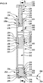
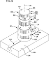
- the one in the Fig. 5 and 6th Individually illustrated modular support frame 108 comprises a support module 118, an extension module 120 and a foot module 122.
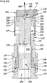
- the support module 118 comprises a base part 124 and a head part 128 which is height-adjustable relative to the base part 124 along a longitudinal axis 126 of the support module 118 and the support frame 108.
- the head part 128 comprises a support element 130, which has a support surface 132 for placing a workpiece 102 or a clamping element 110 on the support module 118.
- the head part 128 is fixed, preferably releasably, on a threaded spindle 134.
- the fixing of the head part on the threaded spindle 134 can take place, for example, by means of a screw connection.
- the external thread 136 of the threaded spindle 134 engages in a complementary internal thread 138 of the base part 124 of the support module 118.
- the external thread 136 of the threaded spindle 134 and the internal thread 138 of the base part 124 are preferably each designed as a trapezoidal thread, preferably as a metric ISO trapezoidal thread according to the DIN 103-1 standard of January 4, 1977.
- these threads as trapezoidal threads, rapid adjustment of the height of the head part 128 relative to the base part 124 is ensured.
- the pitch of the external thread 136 of the threaded spindle 134 and / or the pitch of the internal thread 138 of the base part 124 is preferably at least 4 mm, in particular at least 6 mm, particularly preferably at least 7 mm.
- the base part 124 is designed as an essentially hollow cylindrical sleeve 140 and comprises several parts, for example an upper part 142 on which the internal thread 138 is formed, an intermediate part 144 arranged on the side of the upper part 142 facing away from the head part 128, and an intermediate part 144 on the upper part 142, the lower part 146 arranged facing away from the side of the intermediate part 144.
- the upper part 142, the intermediate part 144 and the lower part 146 of the base part 124 together enclose an interior space 148 of the base part 124, which receives a lower end region of the threaded spindle 134 when the head part 128 is screwed into the internal thread 138 of the base part by screwing the external thread 136 of the threaded spindle 134 124 is moved downward along the longitudinal axis 126 of the support module 118.
- the head part 128 When the head part 128 has reached the desired height, it is secured in this position by tightening a lock nut 150 against the base part 124.
- the threaded spindle 154, the internal thread 138 of the base part 124 and the lock nut 150 thus form components of a height adjustment device 157 of the support module 118, by means of which the height position of the head part 128 relative to the base part 124 can be adjusted.
- the lock nut 150 has two diametrically opposite, essentially flat and parallel actuating surfaces 154 on which a suitable tool can act the lock nut 150, which is in engagement with the external thread 136 of the threaded spindle 134, in order to rotate about the longitudinal axis 126 of the support module 118.
- the lock nut 150 is thus designed as a double flat.
- the lock nut 150 is provided with a corrugation 156 along its circumference.
- the actuation of the lock nut 150 can, for example, by means of a Figures 21 to 23 multifunction tool 158 shown.
- a first end region 160a of the multi-function tool 158 is designed as an open-ended wrench region 162.
- the distance a between the two jaws 164 of the open-ended wrench area 162 corresponds to the distance between the two actuating surfaces 154 of the lock nut 150, so that the open-ended wrench area 162 can be placed on the actuating surfaces 154 of the lock nut 150 around the lock nut 150 about the longitudinal axis 126 of the support module 118 to turn.
- a second end region 160b of the multifunctional tool 158 facing away from the first end region 160a comprises two hook wrench regions 166a and 166b.
- Each of the hook wrench areas 166a, 166b comprises an arcuate area 168, which is designed complementary to a circular disk segment with the diameter D, and a pin 170 arranged at an end area of the arcuate section 168.
- hook wrench areas 166a, 166b can be used to screw the support module 118 to the extension module 120 and / or the extension module 120 to the foot module 122 of the support frame 108, which will be explained in more detail later.
- first end region 160a and the second end region 160b of the multifunctional tool 158 are connected to one another by a bend 172, so that the second end region 160b is offset by the distance s from the first end region 160a.
- This offset s makes it possible to use the multi-function tool 158 even when the space around the support frame 108 is limited.
- the multi-function tool 158 can have one or more, for example two, passage openings 174, which make it possible to hang the multi-function tool 158 on a pin or hook for storage.
- the head part 128 is secured in its height position relative to the base part 124 (see FIG Fig. 5 and 6th ).
- the internal thread 138 of the base part 124 is formed in a threaded hole which extends downward from an upper end face 176 of the upper part 142 of the base part 124 along the longitudinal axis 126 and opens into the interior 148 of the base part 124.
- a stop disk 178 arranged at the lower end of the threaded spindle 134 prevents the threaded spindle 134 from being unscrewed from the internal thread 138 of the base part 124 when the height of the head part 128 is adjusted relative to the base part 124.
- the upper part 142 and the intermediate part 144 of the base part 124 are preferably permanently connected to one another, for example by pressing, gluing, welding or soldering.
- the lower part 146 and the intermediate part 144 of the base part 124 are preferably permanently connected to one another, for example by pressing, gluing, welding or soldering.
- an anti-rotation pin 180 Arranged on the lower part 146 of the base part 124 is an anti-rotation pin 180 which protrudes radially to the longitudinal axis 126 into the interior 148 of the base part 124 and which forms part of an anti-rotation lock 182 which the Extension module 120 secures in a predetermined angular position relative to the support module 118 (with respect to the common longitudinal axis of the support module 118, the extension module 120 and the support frame 108).
- a union nut 184 is arranged at the lower end of the base part 124 and covers part of the intermediate part 144 and part of the lower part 146 of the base part 124 and protrudes downward beyond the lower end of the lower part 146 of the base part 124. In this protruding area, the union nut 184 is provided with an internal thread 186.
- the union nut 184 is provided with an annular collar 188 which protrudes radially inward and engages in a space between a lower end of the intermediate part 144 of the base part 124 on the one hand and a thickened lower end region 190 of the lower part 146 of the base part 124 on the other hand, see above that the union nut 184 is held captive, but displaceably along the longitudinal axis 126 relative to the base part 124 on the base part 124.
- the union nut 184 forms part of a screw connection 192, by means of which the support module 118 can be screwed to the extension module 120 of the support frame 108.
- the outer circumference of the union nut 184 has an upper corrugated area 194 facing the head part 128 of the support module 118, a lower corrugated area 196 facing away from the head part 128 and an actuating area arranged between the upper corrugated area 194 and the lower corrugated area 196 198 on.
- the actuation region 198 has a substantially smooth cylindrical surface 200 with a diameter D.
- the diameter D of the smooth surface 200 of the actuation area 198 of the union nut 184 corresponds to the diameter D of the curved sections 168 of the hook wrench areas 166a and 166b of the in FIG Figures 21 to 23 multifunction tool 158 shown.
- Each of the hook wrench areas 166a, 166b of the multi-function tool 158 can therefore be brought into engagement with the union nut 184 by inserting the pin 170 of the respective hook wrench area 166a or 166b into a recess 202 which is complementary thereto and which is arranged in the actuation area 198 of the union nut 184 and the bottom section 168 of the respective hook wrench area 166a, 166b adjoining the pin 170 is placed against the smooth surface 200 of the actuation area 198.
- the union nut 184 can be rotated around the longitudinal axis 126 of the support module 118 by means of the multi-function tool 158 in order to screw the support module 118 to the extension module 120 which will be explained in more detail below.
- Both hook wrench areas 166a and 166b can each be placed on the actuation area 198 in two different orientations with respect to the recess 202 of the actuation area 198.
- the selection of the hook wrench area 166a or 166b to be created and the selection of the orientation in which the respectively selected hook wrench area 166a or 166b is applied to the actuation area 198 of the union nut 184 is made taking into account the bend 172 of the multi-function tool 158 depending on the space available in the area of the support frame 108 to be assembled is selected.
- the extension module 120 to be coupled with the support module 118 described above is individually in the Fig. 11 and 12th shown.
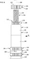
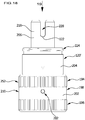
- the extension module 120 comprises an essentially hollow-cylindrical sleeve part 204, a coupling part 206 arranged at an upper end of the sleeve part 204, a lower part 208 arranged at a lower end of the sleeve part 204, which is preferably constructed in exactly the same way as the lower part 146 of the support module 118, and a union nut 210 partially covering the sleeve part 204 and the lower part 208 of the extension module 120, which is preferably designed exactly like the union nut 184 of the support module 118 and thus in the same way as the union nut 184 of the support module 118 by means of the hook wrench areas 166a, 166b of the multi-function tool 158 can be operated.
- the inner space 212 is closed at its upper end by the coupling part 206, which is preferably inserted into an upper end region of the sleeve part 204.
- the coupling part 206 is preferably captively connected to the sleeve part 204, for example by pressing, gluing, welding or soldering.
- the coupling part 206 comprises a holding section 214 inserted into the sleeve part 204, a threaded section 216 adjoining the holding section 214 at the top, which has a larger outer diameter than the holding section 214, and an anti-rotation section 218 arranged on the side of the threaded section 216 facing away from the holding section 214 , which has a smaller outer diameter than the threaded portion 216.
- the anti-rotation section 218 has on its circumference an anti-rotation groove 220 running in the axial direction, i.e. parallel to the longitudinal axis 126 of the extension module 120, the groove width b of which essentially corresponds to the diameter of the anti-rotation pin 180 of the support module 118.
- the anti-rotation section 218 of the coupling part 206 of the extension module 120 is inserted into the interior 148 of the support module 118 in such a way that the anti-rotation pin 180 of the support module 118 engages with the anti-rotation groove 220 of the extension module 120.
- the anti-rotation pin 180 of the support module 118 preferably rests against a lower edge 222 of the anti-rotation groove 220.
- the extension module 120 is secured in a predetermined angular position with respect to the common longitudinal axis 126 of the support module 118 and the extension module 120 relative to the support module 118 by means of the anti-rotation lock 182 formed by the anti-rotation pin 180 of the support module 118 and the anti-rotation groove 220 of the extension module 120 .
- the extension module 120 can be detachably connected to the support module 118 by means of the screw connection 192, which, in addition to the union nut 184 of the support module 118, has an external thread 224 complementary to the internal thread 186 of the union nut 184 on the outer circumference of the threaded section 216 of the coupling part 206 of the extension module 120 includes.
- the union nut 184 of the support module 118 can be screwed onto the external thread 224 of the extension module 120, around the extension module 120 to be screwed to the support module 118.
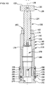
- the foot module 122 of the Fig. 5 and 6th support frame 108 shown is in the Figures 13 to 16 shown individually and comprises a base plate 226 that can be placed on the clamping body 106 and a base element 228 carried by the base plate 226.
- the base element 228 comprises an anti-rotation section 230, which is preferably designed exactly like the anti-rotation section 218 of the coupling part 206 of the extension module 120.
- the anti-rotation section 230 has an anti-rotation groove 220 of width b which extends in the axial direction.
- the anti-rotation section 230 of the base element 228 is followed by a threaded section 234 of the base element 228, which is preferably designed essentially exactly like the threaded section 216 of the coupling part 206 of the extension module 120, that is, in the direction of the base plate 226.
- the threaded section 234 of the base element 228 has, in particular, an external thread 238 which is complementary to an internal thread 236 of the union nut 210 of the extension module 120.
- the threaded section 234 of the base element 228 is followed by a connection section 240 of the base element 228, by means of which the base element 228 can be connected - preferably detachably - to the base plate 226 at the bottom, i.e. towards the base plate 226.
- the connecting section 240 can have one or more threaded blind holes 242 (see FIG Fig. 5 ), into each of which a fastening screw 244 can be screwed, which penetrates a stepped passage opening 246 in the base plate 226.
- the foot module 122 is mounted on the extension module 120 of the support frame 108 by inserting the anti-rotation section 230 of the base element 228 of the foot module 122 into the interior 212 of the extension module 120 such that the anti-rotation pin 248 on the lower part 208 of the extension module 120 engages with the Anti-rotation groove 232 on anti-rotation section 230 of base element 228 of foot module 122, as a result of which foot module 122 is secured in a predetermined angular position in relation to common longitudinal axis 126 of extension module 120 and foot module 122 relative to extension module 120.
- the anti-rotation pin 248 of the extension module 120 and the anti-rotation groove 232 of the foot module 122 thus together form an anti-rotation lock 250, by means of which the foot module 122 can be secured in a predetermined angular position relative to the extension module 120.
- the union nut 120 is then rotated about the longitudinal axis 126 of the extension module 120, for example by means of one of the hook wrench areas 166a or 166b of the multi-function tool 158, so that its internal thread 236 engages with the external thread 238 of the threaded section 234 of the base element 228 of the foot module 122.
- the external thread 238 of the foot module 122 and the union nut 210 of the extension module 120 thus together form a screw connection 252, by means of which the foot module 122 can be screwed to the extension module 120.
- This screw connection 252 between the foot module 122 and the extension module 120 is designed to be compatible with the screw connection 192 between the extension module 120 and the support module 118, so that the foot module 122 can alternatively also be screwed directly to the support module 118.
- the anti-rotation device 250 between the foot module 122 and the extension module 120 is preferably designed to be compatible with the anti-rotation device 182 between the extension module 120 and the support module 118, so that the foot module 122 is also directly on the support module 118 in a predetermined angular position relative to the longitudinal axis 126 relative to the support module 118 can be secured.
- the base plate 226 of the foot module 122 has one or more mounting passage openings 254, through which one or more mounting means 256 (see FIGS Fig. 2 and 4th ) up to a thread of a respective associated T-slot nut 258 (see Fig. 3 ), which is arranged in one of the T-slots 116 of the clamping body 106, can extend into it, in order to mount the base plate 226 and thus the foot module 122 detachably on the clamping body 106.
- Each of the mounting means 256 can comprise, for example, a threaded bolt, a nut and a washer or a mounting screw.
- Each of the assembly passage openings 254 is preferably designed as an elongated hole 260.
- a plurality of assembly passage openings 254 are designed as elongated holes 260, then these preferably extend along diverging longitudinal directions 262.
- the distances between adjacent assembly passage openings 254 increase as the distance from the base element 228 of the foot module 122 increases.
- the support module 118 is directly connected to a base element 152 without the interposition of an extension module 120, which is preferably designed exactly like the base element 228 of the above-described foot module 122, which is due to the compatibility between the screw connections 192 and 252 described above and between the above described anti-rotation locks 182 and 250 is easily possible.
- FIG. 1 and 2 support frames 108d and 108e shown have this in the Figures 8-10 illustrated structure, in which a support module 118 is directly combined with a base element 152.
- the support frames 108d and 108e are mounted on the clamping body 106 by means of an adapter element 262, as is shown in the sectional illustration of FIG Fig. 31 is shown.
- the adapter element 262 comprises an upper threaded section 264, which is provided with an external thread 266, a lower threaded section 268, which is provided with an external thread 270, and a central section 272 connecting the upper threaded section 264 and the lower threaded section 268 to one another.
- the external thread 270 of the lower thread section 268 of the adapter element 262 engages with an internal thread 274 of a T-slot nut 258, which is configured complementarily thereto and which is arranged in a T-groove 116 of the clamping body 106.
- the middle section 272 of the adapter element 262 is received in a — preferably essentially cylindrical — interior space 276 of the base element 152.
- the external thread 266 of the upper threaded section 264 engages with an internal thread 278 of a threaded blind hole 280, which extends upward from the interior 276 of the base element 152.
- the base element 152 is thus detachably mounted on the clamping body 106 by means of the adapter element 262.
- the illustrated support frame 108c of the clamping arrangement 100 differs from the above-described support frame 108a in that the extension module 120 described above is replaced by a shorter extension module 120 ', which is in the Figures 17 to 20 is shown individually.
- This connection can be made, for example, by pressing, gluing, welding or soldering.
- the anti-rotation section 218 and the threaded section 216 of the modified coupling part 206 ' are constructed in exactly the same way as the anti-rotation section 218 and the threaded section 216 of the coupling part 206 of the long extension module 120, so that the anti-rotation device 182 and the screw connection 192 of the short extension module 120' are compatible with the Anti-twist device 182 or with the screw connection 192 of the long extension module 120.
- the lower part 208 of the short extension module 120 ′ is designed exactly like the lower part 208 of the long extension module 120.
- the union nut 210 of the short extension module 120 ′ is designed exactly like the union nut 210 of the long extension module 120.
- the support frame 108b shown is composed of a support module 118 and two short extension modules 120 'mounted one above the other.
- This support frame 108b is mounted on the clamping body 106, as with the support frames 108d and 108e, by means of a base element 152 each, which is mounted on the lower short extension module 120 ', and an adapter element 262, which connects the base element 152 to a T-slot nut 258 arranged in a T-slot 116 of the clamping body 106.
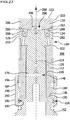
- support module 118 ' differs from the support module 118 described above in that the external thread 136 of the threaded spindle 134 and the internal thread 138 of the base part 124 of the support module 118' are not a trapezoidal thread, but rather are preferably designed as a fine thread, in particular as a metric ISO fine thread according to the DIN 13-2 standard of November 1999.
- the pitch of the external thread 136 of the threaded spindle 134 and / or the pitch of the internal thread 138 of the base part 124 is preferably at most 4 mm, in particular at most 3 mm, particularly preferably at most 2 mm.
- a fine thread offers the further advantage that it has a large core diameter, as a result of which the component provided with the fine thread, in particular the threaded spindle 134, is little weakened by the generation of the fine thread and thus has great mechanical stability.
- the support module 118 ′ in contrast to the support module 118 described above, does not include a lock nut 150.
- Such a lock nut 150 is not required due to the use of a fine thread.
- the threaded spindle 134 in this embodiment has a thickened upper end region 282, which is provided on its outer circumference with two essentially flat actuating surfaces 284 that mutually overlap are diametrically opposite and are aligned essentially parallel to one another, so that the upper end region 282 of the threaded spindle 134 is designed as a two-flat surface.
- the distance between the two actuation surfaces 284 of the threaded spindle 134 corresponds to the distance a of the jaws 164 of the open-ended wrench area 162 of the multi-function tool 158 (see FIG Fig. 22 ), so that the threaded spindle 134 in this embodiment can be rotated about the longitudinal axis 126 of the support module 118 'by means of the open-ended wrench area 162 of the multifunctional tool 158 placed on the actuating surfaces 284.
- the support element 130 on the support surface 132 of which the workpiece 102 to be clamped or a clamping element 110 can be placed, is not rigidly attached to the threaded spindle 134 in this embodiment, but is designed as an angle compensation element 286 which, relative to the longitudinal axis 126 of the support module 118 'from the in Fig. 27 position shown in the in Fig. 28 angular compensation position shown is pivotable, in which the normal direction 288 of the support surface 132 is inclined with respect to the longitudinal axis 126.
- the angle compensation element 286 is, for example, held in a non-positive manner, in particular by a magnetic holding force, on the threaded spindle 134 serving as an angle compensation element carrier 293.
- the magnetic holding force can be generated, for example, by means of one or more magnet elements 288 which are arranged on the upper side of the threaded spindle 134 facing the angle compensation element 286.
- one or more magnet elements are arranged on the angle compensation element 286.
- the magnetic elements 288 are preferably designed as permanent magnets.
- the underside 290 of the angle compensating element 286 facing the threaded spindle 134 is preferably designed to be essentially spherically curved, and the top 292 of the threaded spindle 134 facing the angle compensating element 286 is preferably designed to be complementary to the spherical underside 290 of the angle compensating element 286 in order to pivot the angle compensating element 286 relative to the To enable longitudinal axis 126 of the support module 118 '.
- a stop element 294 which can be designed, for example, as a grub screw 296, the longitudinal axis of which is parallel to the longitudinal axis 126 of the support module 118 'and which is screwed into a threaded blind hole on the top 292 of the threaded spindle 134.
- the stop element 294 engages in a recess 298 on the underside 290 of the angle compensation element 286, the extent of which determines the maximum angle by which the angle compensation element 286 from the in FIG Fig. 27 starting position shown is deflectable.
- the angle compensation element 286 can be provided with a corrugation 300 on its outer circumference in order to facilitate the handling of the angle compensation element 286.
- the threaded spindle 134 of the support module 118 ' is provided with a cover sleeve 302, which extends from the upper end region 282 of the threaded spindle 134 downwards and in each height position of the head part 128 of the support module 118' formed from the threaded spindle 134 and the angle compensation element 286 relative to the base part 124 of the support module 118 'covers the space between the upper end region 282 of the threaded spindle 134 on the one hand and an upper edge 304 of the base part 124 on the other hand, so that no impurities, in particular no chips or liquid impurities such as lubricants or coolants, from an outer space 306 of the Support module 118 'can reach the external thread 136 of the threaded spindle 134.
- a lower end region 308 of the cover sleeve 302 slides on the outer circumference of the base part 124 when the head part 128 is adjusted in height relative to the base part 124.
- the support module 118 'differs from the support module 118 described above in that the base part 124 does not include an intermediate part 144, but instead the lower part 146, which is preferably designed exactly like the lower part 146 of the base part 124 of the support module 118, directly with the Upper part 142 of the base part 124 of the support module 118 'is connected.
- This connection can be made, for example, by pressing, gluing, welding or soldering.
- the support module 118 ′ can be combined with one or more of the extension modules 120 or 120 ′ and / or with a foot module 122 in order to form a support frame 108.
- the second embodiment 118 ′ corresponds in terms of structure, function and method of manufacture to the first embodiment 118 of the support module, to the above description of which reference is made in this respect.
Landscapes
- Engineering & Computer Science (AREA)
- Mechanical Engineering (AREA)
- Surgical Instruments (AREA)
- Jigs For Machine Tools (AREA)
Applications Claiming Priority (1)
| Application Number | Priority Date | Filing Date | Title |
|---|---|---|---|
| DE102019130877.1A DE102019130877A1 (de) | 2019-11-15 | 2019-11-15 | Modularer Abstützbock |
Publications (2)
| Publication Number | Publication Date |
|---|---|
| EP3822021A1 true EP3822021A1 (fr) | 2021-05-19 |
| EP3822021B1 EP3822021B1 (fr) | 2024-10-23 |
Family
ID=73343914
Family Applications (1)
| Application Number | Title | Priority Date | Filing Date |
|---|---|---|---|
| EP20206935.7A Active EP3822021B1 (fr) | 2019-11-15 | 2020-11-11 | Appui modulaire |
Country Status (4)
| Country | Link |
|---|---|
| EP (1) | EP3822021B1 (fr) |
| DE (1) | DE102019130877A1 (fr) |
| ES (1) | ES2997198T3 (fr) |
| PL (1) | PL3822021T3 (fr) |
Citations (4)
| Publication number | Priority date | Publication date | Assignee | Title |
|---|---|---|---|---|
| US399926A (en) * | 1889-03-19 | Charles e | ||
| US3709479A (en) * | 1970-07-13 | 1973-01-09 | J Dolphin | Setup support |
| DE8903660U1 (de) * | 1989-03-20 | 1989-05-18 | Siemens AG, 1000 Berlin und 8000 München | Stützvorrichtung für Werkstücke |
| EP0441437A1 (fr) * | 1990-02-09 | 1991-08-14 | SALVAGNINI S.p.A. | Eléments d'ancrage ajustable pour éléments de serrage sur un support palette |
Family Cites Families (5)
| Publication number | Priority date | Publication date | Assignee | Title |
|---|---|---|---|---|
| CH259892A (de) * | 1946-05-04 | 1949-02-15 | Schmid & Soehne | Höhenstellvorrichtung für Einrichtungen zum Aufspannen von Werkstücken auf Werkzeugmaschinen, Anreissplatten und dergleichen. |
| DE8703472U1 (de) * | 1987-03-07 | 1987-04-16 | Horst Witte Entwicklungs- und Vertriebs KG, 2122 Bleckede | Schraubbock zum Unterstützen, Spannen und Richten von Werkstücken |
| DE29922944U1 (de) * | 1999-12-29 | 2000-03-02 | Form + Test Seidner + Co GmbH, 88499 Riedlingen | Aufspannbock zur Abstützung einer Spannplatte |
| CN103068527B (zh) * | 2010-08-24 | 2015-09-30 | Fcs系统有限责任公司 | 用于机械工件的锁定装置 |
| DE202013101539U1 (de) * | 2013-04-11 | 2013-04-23 | Horst Witte Gerätebau Barskamp KG | Abstandsjustierelement |
-
2019
- 2019-11-15 DE DE102019130877.1A patent/DE102019130877A1/de not_active Withdrawn
-
2020
- 2020-11-11 ES ES20206935T patent/ES2997198T3/es active Active
- 2020-11-11 EP EP20206935.7A patent/EP3822021B1/fr active Active
- 2020-11-11 PL PL20206935.7T patent/PL3822021T3/pl unknown
Patent Citations (4)
| Publication number | Priority date | Publication date | Assignee | Title |
|---|---|---|---|---|
| US399926A (en) * | 1889-03-19 | Charles e | ||
| US3709479A (en) * | 1970-07-13 | 1973-01-09 | J Dolphin | Setup support |
| DE8903660U1 (de) * | 1989-03-20 | 1989-05-18 | Siemens AG, 1000 Berlin und 8000 München | Stützvorrichtung für Werkstücke |
| EP0441437A1 (fr) * | 1990-02-09 | 1991-08-14 | SALVAGNINI S.p.A. | Eléments d'ancrage ajustable pour éléments de serrage sur un support palette |
Also Published As
| Publication number | Publication date |
|---|---|
| ES2997198T3 (en) | 2025-02-14 |
| EP3822021B1 (fr) | 2024-10-23 |
| DE102019130877A1 (de) | 2021-05-20 |
| PL3822021T3 (pl) | 2025-03-10 |
Similar Documents
| Publication | Publication Date | Title |
|---|---|---|
| EP0541904A1 (fr) | Table, en particulier pour la préparation et le soudage | |
| DE102011113494A1 (de) | Spannsystem sowie Grundkörper, Spannzange und Rotationswerkzeug dafür und ein Installationsverfahren für das Rotationswerkzeug im Spannsystem | |
| DE69301597T2 (de) | Rohrträger | |
| WO1994005451A1 (fr) | Dispositif de serrage pour le raccordement de broches de machine a des porte-outils | |
| EP1048544B1 (fr) | Articulation pour rames de véhicules ferroviaires | |
| WO2019086079A1 (fr) | Boulon de serrage, plateau de table et systeme de serrage | |
| EP1660262B1 (fr) | Point d'assemblage d'un outil | |
| EP3822021B1 (fr) | Appui modulaire | |
| DE19546703C1 (de) | Befestigungselement für plattenförmige Bauelemente | |
| EP0047961B1 (fr) | Accouplement de rotule d'attelage pour véhicules moteur | |
| EP0250638A1 (fr) | Tendeur pour ressort de compression | |
| DE2225747C2 (de) | Schneidwerkzeug für die spanabhebende Bearbeitung | |
| DE10232041A1 (de) | Lenksäule | |
| DE19805833B4 (de) | Verbindungseinrichtung zum Verbinden zweier Körper | |
| DE29819740U1 (de) | Federspanner für Schraubenfedern mit wenigstens einem Federteller | |
| DE10261000B3 (de) | Kombinationsfederspanner | |
| EP0806322B1 (fr) | Pare-chocs | |
| DE10032966B4 (de) | Hohlbohrer und Wechselhalter hierfür | |
| DE3613601A1 (de) | Montagevorrichtung | |
| DE9305188U1 (de) | Schnellspannvorrichtung für Stichsägeblätter | |
| DE102020101062B4 (de) | Werkstückspannvorrichtung mit Kopplungskörper zwischen Klemmkörper und Gewindespindel | |
| DE29702673U1 (de) | Federspanner zum Spannen von Schraubenfedern mit zwei Druckplatten | |
| DE19856684C2 (de) | Gelenk | |
| DE2133446A1 (de) | Axialspannfutter | |
| CH666093A5 (de) | Schraubverbindung. |
Legal Events
| Date | Code | Title | Description |
|---|---|---|---|
| PUAI | Public reference made under article 153(3) epc to a published international application that has entered the european phase |
Free format text: ORIGINAL CODE: 0009012 |
|
| STAA | Information on the status of an ep patent application or granted ep patent |
Free format text: STATUS: THE APPLICATION HAS BEEN PUBLISHED |
|
| AK | Designated contracting states |
Kind code of ref document: A1 Designated state(s): AL AT BE BG CH CY CZ DE DK EE ES FI FR GB GR HR HU IE IS IT LI LT LU LV MC MK MT NL NO PL PT RO RS SE SI SK SM TR |
|
| STAA | Information on the status of an ep patent application or granted ep patent |
Free format text: STATUS: REQUEST FOR EXAMINATION WAS MADE |
|
| 17P | Request for examination filed |
Effective date: 20211117 |
|
| RBV | Designated contracting states (corrected) |
Designated state(s): AL AT BE BG CH CY CZ DE DK EE ES FI FR GB GR HR HU IE IS IT LI LT LU LV MC MK MT NL NO PL PT RO RS SE SI SK SM TR |
|
| P01 | Opt-out of the competence of the unified patent court (upc) registered |
Effective date: 20230519 |
|
| REG | Reference to a national code |
Ref country code: DE Ref legal event code: R079 Free format text: PREVIOUS MAIN CLASS: B23Q0003100000 Ipc: B25B0005000000 Ref country code: DE Ref legal event code: R079 Ref document number: 502020009552 Country of ref document: DE Free format text: PREVIOUS MAIN CLASS: B23Q0003100000 Ipc: B25B0005000000 |
|
| GRAP | Despatch of communication of intention to grant a patent |
Free format text: ORIGINAL CODE: EPIDOSNIGR1 |
|
| STAA | Information on the status of an ep patent application or granted ep patent |
Free format text: STATUS: GRANT OF PATENT IS INTENDED |
|
| RIC1 | Information provided on ipc code assigned before grant |
Ipc: B25B 5/00 20060101AFI20240503BHEP |
|
| INTG | Intention to grant announced |
Effective date: 20240531 |
|
| GRAS | Grant fee paid |
Free format text: ORIGINAL CODE: EPIDOSNIGR3 |
|
| GRAA | (expected) grant |
Free format text: ORIGINAL CODE: 0009210 |
|
| STAA | Information on the status of an ep patent application or granted ep patent |
Free format text: STATUS: THE PATENT HAS BEEN GRANTED |
|
| AK | Designated contracting states |
Kind code of ref document: B1 Designated state(s): AL AT BE BG CH CY CZ DE DK EE ES FI FR GB GR HR HU IE IS IT LI LT LU LV MC MK MT NL NO PL PT RO RS SE SI SK SM TR |
|
| REG | Reference to a national code |
Ref country code: GB Ref legal event code: FG4D Free format text: NOT ENGLISH |
|
| REG | Reference to a national code |
Ref country code: CH Ref legal event code: EP |
|
| REG | Reference to a national code |
Ref country code: DE Ref legal event code: R096 Ref document number: 502020009552 Country of ref document: DE |
|
| REG | Reference to a national code |
Ref country code: IE Ref legal event code: FG4D Free format text: LANGUAGE OF EP DOCUMENT: GERMAN |
|
| REG | Reference to a national code |
Ref country code: ES Ref legal event code: FG2A Ref document number: 2997198 Country of ref document: ES Kind code of ref document: T3 Effective date: 20250214 |
|
| REG | Reference to a national code |
Ref country code: LT Ref legal event code: MG9D |
|
| REG | Reference to a national code |
Ref country code: NL Ref legal event code: MP Effective date: 20241023 |
|
| PG25 | Lapsed in a contracting state [announced via postgrant information from national office to epo] |
Ref country code: NL Free format text: LAPSE BECAUSE OF FAILURE TO SUBMIT A TRANSLATION OF THE DESCRIPTION OR TO PAY THE FEE WITHIN THE PRESCRIBED TIME-LIMIT Effective date: 20241023 |
|
| PG25 | Lapsed in a contracting state [announced via postgrant information from national office to epo] |
Ref country code: NL Free format text: LAPSE BECAUSE OF FAILURE TO SUBMIT A TRANSLATION OF THE DESCRIPTION OR TO PAY THE FEE WITHIN THE PRESCRIBED TIME-LIMIT Effective date: 20241023 |
|
| PG25 | Lapsed in a contracting state [announced via postgrant information from national office to epo] |
Ref country code: IS Free format text: LAPSE BECAUSE OF FAILURE TO SUBMIT A TRANSLATION OF THE DESCRIPTION OR TO PAY THE FEE WITHIN THE PRESCRIBED TIME-LIMIT Effective date: 20250223 Ref country code: HR Free format text: LAPSE BECAUSE OF FAILURE TO SUBMIT A TRANSLATION OF THE DESCRIPTION OR TO PAY THE FEE WITHIN THE PRESCRIBED TIME-LIMIT Effective date: 20241023 Ref country code: PT Free format text: LAPSE BECAUSE OF FAILURE TO SUBMIT A TRANSLATION OF THE DESCRIPTION OR TO PAY THE FEE WITHIN THE PRESCRIBED TIME-LIMIT Effective date: 20250224 |
|
| PG25 | Lapsed in a contracting state [announced via postgrant information from national office to epo] |
Ref country code: FI Free format text: LAPSE BECAUSE OF FAILURE TO SUBMIT A TRANSLATION OF THE DESCRIPTION OR TO PAY THE FEE WITHIN THE PRESCRIBED TIME-LIMIT Effective date: 20241023 |
|
| PG25 | Lapsed in a contracting state [announced via postgrant information from national office to epo] |
Ref country code: BG Free format text: LAPSE BECAUSE OF FAILURE TO SUBMIT A TRANSLATION OF THE DESCRIPTION OR TO PAY THE FEE WITHIN THE PRESCRIBED TIME-LIMIT Effective date: 20241023 |
|
| PG25 | Lapsed in a contracting state [announced via postgrant information from national office to epo] |
Ref country code: NO Free format text: LAPSE BECAUSE OF FAILURE TO SUBMIT A TRANSLATION OF THE DESCRIPTION OR TO PAY THE FEE WITHIN THE PRESCRIBED TIME-LIMIT Effective date: 20250123 |
|
| PG25 | Lapsed in a contracting state [announced via postgrant information from national office to epo] |
Ref country code: LV Free format text: LAPSE BECAUSE OF FAILURE TO SUBMIT A TRANSLATION OF THE DESCRIPTION OR TO PAY THE FEE WITHIN THE PRESCRIBED TIME-LIMIT Effective date: 20241023 Ref country code: GR Free format text: LAPSE BECAUSE OF FAILURE TO SUBMIT A TRANSLATION OF THE DESCRIPTION OR TO PAY THE FEE WITHIN THE PRESCRIBED TIME-LIMIT Effective date: 20250124 |
|
| PG25 | Lapsed in a contracting state [announced via postgrant information from national office to epo] |
Ref country code: RS Free format text: LAPSE BECAUSE OF FAILURE TO SUBMIT A TRANSLATION OF THE DESCRIPTION OR TO PAY THE FEE WITHIN THE PRESCRIBED TIME-LIMIT Effective date: 20250123 |
|
| PG25 | Lapsed in a contracting state [announced via postgrant information from national office to epo] |
Ref country code: SM Free format text: LAPSE BECAUSE OF FAILURE TO SUBMIT A TRANSLATION OF THE DESCRIPTION OR TO PAY THE FEE WITHIN THE PRESCRIBED TIME-LIMIT Effective date: 20241023 |
|
| PG25 | Lapsed in a contracting state [announced via postgrant information from national office to epo] |
Ref country code: MC Free format text: LAPSE BECAUSE OF FAILURE TO SUBMIT A TRANSLATION OF THE DESCRIPTION OR TO PAY THE FEE WITHIN THE PRESCRIBED TIME-LIMIT Effective date: 20241023 |
|
| PG25 | Lapsed in a contracting state [announced via postgrant information from national office to epo] |
Ref country code: DK Free format text: LAPSE BECAUSE OF FAILURE TO SUBMIT A TRANSLATION OF THE DESCRIPTION OR TO PAY THE FEE WITHIN THE PRESCRIBED TIME-LIMIT Effective date: 20241023 |
|
| PG25 | Lapsed in a contracting state [announced via postgrant information from national office to epo] |
Ref country code: LU Free format text: LAPSE BECAUSE OF NON-PAYMENT OF DUE FEES Effective date: 20241111 |
|
| PG25 | Lapsed in a contracting state [announced via postgrant information from national office to epo] |
Ref country code: EE Free format text: LAPSE BECAUSE OF FAILURE TO SUBMIT A TRANSLATION OF THE DESCRIPTION OR TO PAY THE FEE WITHIN THE PRESCRIBED TIME-LIMIT Effective date: 20241023 |
|
| PG25 | Lapsed in a contracting state [announced via postgrant information from national office to epo] |
Ref country code: RO Free format text: LAPSE BECAUSE OF FAILURE TO SUBMIT A TRANSLATION OF THE DESCRIPTION OR TO PAY THE FEE WITHIN THE PRESCRIBED TIME-LIMIT Effective date: 20241023 |
|
| REG | Reference to a national code |
Ref country code: DE Ref legal event code: R097 Ref document number: 502020009552 Country of ref document: DE |
|
| PG25 | Lapsed in a contracting state [announced via postgrant information from national office to epo] |
Ref country code: SK Free format text: LAPSE BECAUSE OF FAILURE TO SUBMIT A TRANSLATION OF THE DESCRIPTION OR TO PAY THE FEE WITHIN THE PRESCRIBED TIME-LIMIT Effective date: 20241023 |
|
| PG25 | Lapsed in a contracting state [announced via postgrant information from national office to epo] |
Ref country code: CZ Free format text: LAPSE BECAUSE OF FAILURE TO SUBMIT A TRANSLATION OF THE DESCRIPTION OR TO PAY THE FEE WITHIN THE PRESCRIBED TIME-LIMIT Effective date: 20241023 |
|
| REG | Reference to a national code |
Ref country code: BE Ref legal event code: MM Effective date: 20241130 |
|
| PLBE | No opposition filed within time limit |
Free format text: ORIGINAL CODE: 0009261 |
|
| STAA | Information on the status of an ep patent application or granted ep patent |
Free format text: STATUS: NO OPPOSITION FILED WITHIN TIME LIMIT |
|
| PG25 | Lapsed in a contracting state [announced via postgrant information from national office to epo] |
Ref country code: SE Free format text: LAPSE BECAUSE OF FAILURE TO SUBMIT A TRANSLATION OF THE DESCRIPTION OR TO PAY THE FEE WITHIN THE PRESCRIBED TIME-LIMIT Effective date: 20241023 |
|
| GBPC | Gb: european patent ceased through non-payment of renewal fee |
Effective date: 20250123 |
|
| 26N | No opposition filed |
Effective date: 20250724 |
|
| PGFP | Annual fee paid to national office [announced via postgrant information from national office to epo] |
Ref country code: PL Payment date: 20250912 Year of fee payment: 6 |
|
| PG25 | Lapsed in a contracting state [announced via postgrant information from national office to epo] |
Ref country code: GB Free format text: LAPSE BECAUSE OF NON-PAYMENT OF DUE FEES Effective date: 20250123 Ref country code: BE Free format text: LAPSE BECAUSE OF NON-PAYMENT OF DUE FEES Effective date: 20241130 |
|
| PGFP | Annual fee paid to national office [announced via postgrant information from national office to epo] |
Ref country code: FR Payment date: 20250908 Year of fee payment: 6 |
|
| PG25 | Lapsed in a contracting state [announced via postgrant information from national office to epo] |
Ref country code: IE Free format text: LAPSE BECAUSE OF NON-PAYMENT OF DUE FEES Effective date: 20241111 |
|
| REG | Reference to a national code |
Ref country code: CH Ref legal event code: U11 Free format text: ST27 STATUS EVENT CODE: U-0-0-U10-U11 (AS PROVIDED BY THE NATIONAL OFFICE) Effective date: 20251201 |
|
| PGFP | Annual fee paid to national office [announced via postgrant information from national office to epo] |
Ref country code: DE Payment date: 20251124 Year of fee payment: 6 |
|
| PGFP | Annual fee paid to national office [announced via postgrant information from national office to epo] |
Ref country code: AT Payment date: 20251027 Year of fee payment: 6 |
|
| PGFP | Annual fee paid to national office [announced via postgrant information from national office to epo] |
Ref country code: IT Payment date: 20251022 Year of fee payment: 6 |
|
| PGFP | Annual fee paid to national office [announced via postgrant information from national office to epo] |
Ref country code: TR Payment date: 20251031 Year of fee payment: 6 |
|
| PGFP | Annual fee paid to national office [announced via postgrant information from national office to epo] |
Ref country code: CH Payment date: 20251201 Year of fee payment: 6 |
|
| PGFP | Annual fee paid to national office [announced via postgrant information from national office to epo] |
Ref country code: ES Payment date: 20251210 Year of fee payment: 6 |
|
| PG25 | Lapsed in a contracting state [announced via postgrant information from national office to epo] |
Ref country code: HU Free format text: LAPSE BECAUSE OF FAILURE TO SUBMIT A TRANSLATION OF THE DESCRIPTION OR TO PAY THE FEE WITHIN THE PRESCRIBED TIME-LIMIT; INVALID AB INITIO Effective date: 20201111 |
|
| PG25 | Lapsed in a contracting state [announced via postgrant information from national office to epo] |
Ref country code: CY Free format text: LAPSE BECAUSE OF FAILURE TO SUBMIT A TRANSLATION OF THE DESCRIPTION OR TO PAY THE FEE WITHIN THE PRESCRIBED TIME-LIMIT; INVALID AB INITIO Effective date: 20201111 |