EP3822021B1 - Modularer abstützbock - Google Patents
Modularer abstützbock Download PDFInfo
- Publication number
- EP3822021B1 EP3822021B1 EP20206935.7A EP20206935A EP3822021B1 EP 3822021 B1 EP3822021 B1 EP 3822021B1 EP 20206935 A EP20206935 A EP 20206935A EP 3822021 B1 EP3822021 B1 EP 3822021B1
- Authority
- EP
- European Patent Office
- Prior art keywords
- module
- support
- support module
- accordance
- extension
- Prior art date
- Legal status (The legal status is an assumption and is not a legal conclusion. Google has not performed a legal analysis and makes no representation as to the accuracy of the status listed.)
- Active
Links
Images














Classifications
-
- B—PERFORMING OPERATIONS; TRANSPORTING
- B23—MACHINE TOOLS; METAL-WORKING NOT OTHERWISE PROVIDED FOR
- B23Q—DETAILS, COMPONENTS, OR ACCESSORIES FOR MACHINE TOOLS, e.g. ARRANGEMENTS FOR COPYING OR CONTROLLING; MACHINE TOOLS IN GENERAL CHARACTERISED BY THE CONSTRUCTION OF PARTICULAR DETAILS OR COMPONENTS; COMBINATIONS OR ASSOCIATIONS OF METAL-WORKING MACHINES, NOT DIRECTED TO A PARTICULAR RESULT
- B23Q3/00—Devices holding, supporting, or positioning work or tools, of a kind normally removable from the machine
- B23Q3/02—Devices holding, supporting, or positioning work or tools, of a kind normally removable from the machine for mounting on a work-table, tool-slide, or analogous part
- B23Q3/10—Auxiliary devices, e.g. bolsters, extension members
- B23Q3/103—Constructional elements used for constructing work holders
-
- B—PERFORMING OPERATIONS; TRANSPORTING
- B23—MACHINE TOOLS; METAL-WORKING NOT OTHERWISE PROVIDED FOR
- B23Q—DETAILS, COMPONENTS, OR ACCESSORIES FOR MACHINE TOOLS, e.g. ARRANGEMENTS FOR COPYING OR CONTROLLING; MACHINE TOOLS IN GENERAL CHARACTERISED BY THE CONSTRUCTION OF PARTICULAR DETAILS OR COMPONENTS; COMBINATIONS OR ASSOCIATIONS OF METAL-WORKING MACHINES, NOT DIRECTED TO A PARTICULAR RESULT
- B23Q3/00—Devices holding, supporting, or positioning work or tools, of a kind normally removable from the machine
- B23Q3/02—Devices holding, supporting, or positioning work or tools, of a kind normally removable from the machine for mounting on a work-table, tool-slide, or analogous part
- B23Q3/10—Auxiliary devices, e.g. bolsters, extension members
- B23Q3/106—Auxiliary devices, e.g. bolsters, extension members extendable members, e.g. extension members
- B23Q3/107—Auxiliary devices, e.g. bolsters, extension members extendable members, e.g. extension members with positive adjustment means
-
- B—PERFORMING OPERATIONS; TRANSPORTING
- B25—HAND TOOLS; PORTABLE POWER-DRIVEN TOOLS; MANIPULATORS
- B25B—TOOLS OR BENCH DEVICES NOT OTHERWISE PROVIDED FOR, FOR FASTENING, CONNECTING, DISENGAGING, OR HOLDING
- B25B5/00—Clamps
- B25B5/003—Combinations of clamps
-
- B—PERFORMING OPERATIONS; TRANSPORTING
- B25—HAND TOOLS; PORTABLE POWER-DRIVEN TOOLS; MANIPULATORS
- B25B—TOOLS OR BENCH DEVICES NOT OTHERWISE PROVIDED FOR, FOR FASTENING, CONNECTING, DISENGAGING, OR HOLDING
- B25B5/00—Clamps
- B25B5/006—Supporting devices for clamps
-
- B—PERFORMING OPERATIONS; TRANSPORTING
- B25—HAND TOOLS; PORTABLE POWER-DRIVEN TOOLS; MANIPULATORS
- B25B—TOOLS OR BENCH DEVICES NOT OTHERWISE PROVIDED FOR, FOR FASTENING, CONNECTING, DISENGAGING, OR HOLDING
- B25B5/00—Clamps
- B25B5/06—Arrangements for positively actuating jaws
- B25B5/10—Arrangements for positively actuating jaws using screws
Definitions
- the present invention relates to a modular support frame, which comprises a support module comprising a base part and a head part that is height-adjustable relative to the base part, and an extension module onto which the support module can be placed.
- Such a support block is used as a component of a clamping arrangement for clamping a workpiece to be machined to a clamping surface of a clamping body and serves to support the workpiece to be clamped or a clamping element, for example a clamping iron, by means of which a clamping force is transmitted to the workpiece to be clamped.
- a clamping element for example a clamping iron
- the EP 0 441 437 A1 and the DE 89 03 660 U1 disclose modular support frames according to the preamble of claim 1.
- the present invention is based on the object of creating a modular support frame of the type mentioned above, which has a higher level of safety and mechanical stability.
- Such an anti-twisting device can in particular comprise an anti-twisting groove and an anti-twisting pin that can be brought into engagement with the anti-twisting groove.
- the anti-twisting groove is arranged on the support module and that the anti-twisting pin is arranged on the extension module.
- the anti-twisting groove is arranged on the extension module and the anti-twisting pin is arranged on the support module.
- a further anti-twisting device by means of which a further extension module, a foot module or a base element can be secured in a predetermined angular position with respect to the longitudinal axis of the support frame relative to the extension module.
- the total height of the modular support frame can be selected as desired using the additional extension module or several additional extension modules.
- the support frame can be mounted with a clamping body in a safe and mechanically stable manner.
- the further anti-twisting device is designed to be compatible with the first anti-twisting device, by means of which the first extension module can be secured in a predetermined angular position with respect to a longitudinal axis of the support bracket relative to the support module, so that the further extension module, the foot module or the base element of the support bracket can be secured directly to the support module in a predetermined angular position with respect to the longitudinal axis of the support bracket relative to the support module.
- the compatibility of the anti-twisting devices of the modular support frame ensures that the individual modules of the support frame, in particular one or more extension modules, a foot module and/or a base element, can be coupled together in a variable number and in a variable order in order to construct a modular support frame with the desired dimensions.
- the mechanical stability of the modular support frame is increased by the provision of a screw connection by means of which the extension module can be screwed to the support module.
- This screw connection includes an external thread and a union nut.
- the external thread is arranged on the support module and the union nut on the extension module.
- the external thread is arranged on the extension module and the union nut is arranged on the support module.
- the further screw connection is preferably designed to be compatible with the first screw connection, by means of which the first extension module can be screwed to the support module, so that the further extension module, the foot module or the base element can be screwed directly to the support module.
- the support module comprises a height adjustment device for the head part, wherein the height adjustment device comprises a threaded spindle and an internal thread and optionally a lock nut.
- the threaded spindle can in particular have a trapezoidal thread, preferably a metric ISO trapezoidal thread according to the standard DIN 103-1 of 4 January 1977.
- the design of the thread of the threaded spindle as a trapezoidal thread enables a quick adjustment of the height of the head part relative to the base part of the support module.
- the pitch of the trapezoidal thread is preferably at least 4 mm, in particular at least 6 mm, particularly preferably at least 7 mm.
- the threaded spindle may also have a fine thread, in particular a metric ISO fine thread in accordance with the DIN 13-2 standard of November 1999.
- the thread of the threaded spindle as a fine thread, a precise height adjustment of the head part relative to the base part of the support module is possible even when the support module is under load.
- the pitch of the fine thread is preferably at most 4 mm, in particular at most 3 mm, particularly preferably at most 2 mm.
- the support module comprises an angle compensation element that can be pivoted relative to a longitudinal axis of the support module.
- the support module comprises a magnetic element, by means of which the angle compensation element is held in different angular positions with respect to the longitudinal axis of the support module on an angle compensation element carrier of the support module.
- such a magnetic element is arranged on the angle compensation element.
- the magnetic element is arranged on the angle compensation element carrier of the support module.
- a magnetic element is arranged on the angle compensation element and a further element is arranged on the angle compensation element carrier of the support module.
- the magnetic element is preferably designed as a permanent magnet.
- the support module comprises a cover, in particular in the form of a cover sleeve, which shields the thread of the threaded spindle - preferably in every height position of the head part relative to the base part of the support module - from an external space of the support module, so that no contamination, in particular no chips or liquid contaminants such as lubricants or coolants, can reach the thread of the threaded spindle from the external space of the support module.
- Such a cover of the thread of the threaded spindle is particularly advantageous if the thread of the threaded spindle is designed as a fine thread, which would otherwise be very susceptible to contamination and wear.
- the clamping arrangement shown serves to clamp a workpiece 102 on a clamping surface 104 of a clamping body 106.
- the clamping body 106 can be designed, for example, as a machine table or as a clamping pallet.
- the clamping arrangement 100 comprises several, for example two, support blocks 108, namely a first, in Fig. 2 right, support frame 108a and a second one in Fig. 2 support bracket 108b shown on the far left, each of which supports a clamping element 110 of the clamping arrangement 100.
- Each of the clamping elements which are designed, for example, as a clamping iron, rests on the workpiece 102 to be clamped on a side of the workpiece 102 facing away from the clamping surface 104 and is pulled towards the clamping surface 104 by means of a respective pull rod 112.
- the clamping force is transmitted from the pull rod 112 to the clamping element 110 by means of a clamping nut 114 which is in engagement with a thread of the respective pull rod 112.
- An end of the pull rod 112 facing away from the clamping nut 114 is in engagement with a T-slot nut which is arranged in a T-slot 116 of the clamping body 106.
- the clamping arrangement 100 comprises several, for example three, support blocks 108, which support the workpiece 102 itself, namely a Fig. 2 support bracket 108c arranged to the right of the support bracket 108b, a Fig. 2 Support bracket 108d arranged to the right of the support bracket 108c and a Fig. 2 support bracket 108e arranged to the right of the support bracket 108d and to the left of the support bracket 108a.
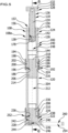
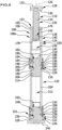
- the support frame 108a shown on the far right will be explained in more detail, which is shown in the Fig. 5 and 6 shown individually in longitudinal section.
- the individually shown modular support frame 108 comprises a support module 118, an extension module 120 and a foot module 122.
- the support module 118 comprises a base part 124 and a head part 128 that is height-adjustable relative to the base part 124 along a longitudinal axis 126 of the support module 118 and the support frame 108.
- the head part 128 comprises a support element 130, which has a support surface 132 for placing a workpiece 102 or a clamping element 110 on the support module 118.
- the head part 128 is fixed, preferably detachably, to a threaded spindle 134.
- the head part can be fixed to the threaded spindle 134, for example, by means of a screw connection.
- the external thread 136 of the threaded spindle 134 engages with a complementary internal thread 138 of the base part 124 of the support module 118.
- the external thread 136 of the threaded spindle 134 and the internal thread 138 of the base part 124 are preferably each designed as a trapezoidal thread, preferably as a metric ISO trapezoidal thread according to the standard DIN 103-1 of January 4, 1977.
- the pitch of the external thread 136 of the threaded spindle 134 and/or the pitch of the internal thread 138 of the base part 124 is at least 4 mm, in particular at least 6 mm, particularly preferably at least 7 mm.
- the base part 124 is designed as a substantially hollow cylindrical sleeve 140 and comprises several parts, for example an upper part 142 on which the internal thread 138 is formed, an intermediate part 144 arranged on the side of the upper part 142 facing away from the head part 128 and a lower part 146 arranged on the side of the intermediate part 144 facing away from the upper part 142.
- the upper part 142, the intermediate part 144 and the lower part 146 of the base part 124 together enclose an interior space 148 of the base part 124, which accommodates a lower end region of the threaded spindle 134 when the head part 128 is moved downward along the longitudinal axis 126 of the support module 118 by screwing the external thread 136 of the threaded spindle 134 into the internal thread 138 of the base part 124.
- the head part 128 When the head part 128 has reached the desired height, it is secured in this position by tightening a lock nut 150 against the base part 124.
- the threaded spindle 154, the internal thread 138 of the base part 124 and the lock nut 150 thus form components of a height adjustment device 157 of the support module 118, by means of which the height position of the head part 128 relative to the base part 124 can be adjusted.
- the lock nut 150 has two diametrically opposed, substantially flat and mutually parallel actuating surfaces 154 which can be engaged by a suitable tool in order to rotate the lock nut 150, which is in engagement with the external thread 136 of the threaded spindle 134, about the longitudinal axis 126 of the support module 118.
- the lock nut 150 is thus designed as a two-flat nut.
- the lock nut 150 is provided with a knurling 156 along its circumference.
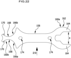
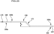
- the lock nut 150 can be actuated, for example, by means of a Fig. 21 to 23 multi-function tool 158 shown.
- a first end region 160a of the multi-function tool 158 is designed as an open-end wrench region 162.
- the distance a between the two jaws 164 of the open-end wrench region 162 corresponds to the distance between the two actuating surfaces 154 of the lock nut 150, so that the open-end wrench region 162 can be placed on the actuating surfaces 154 of the lock nut 150 in order to rotate the lock nut 150 about the longitudinal axis 126 of the support module 118.
- a second end region 160b of the multi-function tool 158 facing away from the first end region 160a comprises two hook wrench regions 166a and 166b.
- Each of the hook wrench areas 166a, 166b comprises an arc area 168, which is formed complementarily to a circular disk segment with the diameter D, and a pin 170 arranged at an end area of the arc section 168.
- hook wrench areas 166a, 166b can be used to screw the support module 118 to the extension module 120 and/or the extension module 120 to the foot module 122 of the support frame 108, which will be explained in more detail later.
- first end region 160a and the second end region 160b of the multi-function tool 158 are connected to one another by an offset 172, so that the second end region 160b is offset by the distance s relative to the first end region 160a.
- This offset s makes it possible to use the multi-function tool 158 even when the space around the support stand 108 is limited.
- the multi-function tool 158 can have one or more, for example two, through openings 174, which make it possible to hang the multi-function tool 158 on a pin or on a hook for storage.
- the head part 128 is secured in its height position relative to the base part 124 (see Fig. 5 and 6 ).
- the internal thread 138 of the base part 124 is formed on a threaded hole which extends downward from an upper end surface 176 of the upper part 142 of the base part 124 along the longitudinal axis 126 and opens into the interior space 148 of the base part 124.
- a stop disk 178 arranged at the lower end of the threaded spindle 134 prevents the threaded spindle 134 from being unscrewed from the internal thread 138 of the base part 124 during the height adjustment of the head part 128 relative to the base part 124.
- the upper part 142 and the intermediate part 144 of the base part 124 are preferably permanently connected to one another, for example by pressing, by gluing, by welding or by soldering.
- the lower part 146 and the intermediate part 144 of the base part 124 are preferably permanently connected to one another, for example by pressing, by gluing, by welding or by soldering.
- an anti-twisting pin 180 is arranged which projects radially to the longitudinal axis 126 into the interior 148 of the base part 124 and forms part of an anti-twisting device 182 which secures the Extension module 120 in a predetermined angular position relative to the support module 118 (with respect to the common longitudinal axis of the support module 118, the extension module 120 and the support frame 108).
- a union nut 184 is arranged at the lower end of the base part 124, which covers a part of the intermediate part 144 and a part of the lower part 146 of the base part 124 and projects downwards over the lower end of the lower part 146 of the base part 124.
- the union nut 184 is provided with an internal thread 186.
- the union nut 184 is provided with an annular collar 188 which projects radially inward and engages in a space between a lower end of the intermediate part 144 of the base part 124 on the one hand and a thickened lower end region 190 of the lower part 146 of the base part 124 on the other hand, so that the union nut 184 is held on the base part 124 in a captive manner but displaceable along the longitudinal axis 126 relative to the base part 124.
- the union nut 184 forms a component of a screw connection 192, by means of which the support module 118 can be screwed to the extension module 120 of the support bracket 108.
- the union nut 184 has on its outer circumference an upper grooved region 194 facing the head part 128 of the support module 118, a lower grooved region 196 facing away from the head part 128 and an actuating region 198 arranged between the upper grooved region 194 and the lower grooved region 196.
- the actuating region 198 has a substantially smooth cylindrical surface 200 with a diameter D.
- the diameter D of the smooth surface 200 of the actuating area 198 of the union nut 184 corresponds to the diameter D of the arc sections 168 of the hook wrench areas 166a and 166b of the Fig. 21 to 23 illustrated multi-function tool 158.
- Each of the hook wrench areas 166a, 166b of the multi-function tool 158 can therefore be brought into engagement with the union nut 184 by inserting the pin 170 of the respective hook wrench area 166a or 166b into a recess 202 which is complementary thereto and which is arranged in the actuating area 198 of the union nut 184, and by placing the base section 168 of the respective hook wrench area 166a, 166b adjacent to the pin 170 against the smooth surface 200 of the actuating area 198.
- the union nut 184 can be rotated about the longitudinal axis 126 of the support module 118 by means of the multi-function tool 158 in order to screw the support module 118 to the extension module 120, which will be explained in more detail below.
- Both hook wrench areas 166a and 166b can each be applied to the actuating area 198 in two different orientations in relation to the recess 202 of the actuating area 198.
- the selection of the hook wrench area 166a or 166b to be applied and the selection of the orientation in which the respectively selected hook wrench area 166a or 166b is applied to the actuating area 198 of the union nut 184 is selected taking into account the offset 172 of the multi-function tool 158 depending on the space conditions in the vicinity of the support frame 108 to be mounted.
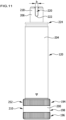
- the extension module 120 to be coupled with the support module 118 described above is individually mounted in the Fig. 11 and 12 shown.
- the extension module 120 comprises a substantially hollow-cylindrical sleeve part 204, a coupling part 206 arranged at an upper end of the sleeve part 204, a lower part 208 arranged at a lower end of the sleeve part 204, which is preferably constructed in exactly the same way as the lower part 146 of the support module 118, and a union nut 210 which partially covers the sleeve part 204 and the lower part 208 of the extension module 120 and which is preferably constructed in exactly the same way as the union nut 184 of the support module 118 and can thus be actuated in the same way as the union nut 184 of the support module 118 by means of the hook wrench areas 166a, 166b of the multi-function tool 158.
- the interior space 212 is closed at its upper end by the coupling part 206, which is preferably inserted into an upper end region of the sleeve part 204.
- the coupling part 206 is preferably captively connected to the sleeve part 204, for example by pressing, by gluing, by welding or by soldering.
- the coupling part 206 comprises a holding section 214 inserted into the sleeve part 204, a threaded section 216 which adjoins the holding section 214 at the top and has a larger outer diameter than the holding section 214, and an anti-twisting section 218 which is arranged on the side of the threaded section 216 facing away from the holding section 214 and has a smaller outer diameter than the threaded section 216.
- the anti-rotation section 218 has on its circumference an anti-rotation groove 220 which runs in the axial direction, that is to say parallel to the longitudinal axis 126 of the extension module 120, the groove width b of which essentially corresponds to the diameter of the anti-rotation pin 180 of the support module 118.
- the anti-twisting section 218 of the coupling part 206 of the extension module 120 is inserted into the interior 148 of the support module 118 such that the anti-twisting pin 180 of the support module 118 engages with the anti-twisting groove 220 of the extension module 120.
- the anti-rotation pin 180 of the support module 118 preferably rests against a lower edge 222 of the anti-rotation groove 220.
- the extension module 120 is secured in a predetermined angular position with respect to the common longitudinal axis 126 of the support module 118 and the extension module 120 relative to the support module 118 by means of the anti-twist device 182 formed by the anti-twist pin 180 of the support module 118 and the anti-twist groove 220 of the extension module 120.
- the extension module 120 can be detachably connected to the support module 118 by means of the screw connection 192, which, in addition to the union nut 184 of the support module 118, comprises an external thread 224 complementary to the internal thread 186 of the union nut 184 on the outer circumference of the threaded portion 216 of the coupling part 206 of the extension module 120.
- the union nut 184 of the support module 118 can be screwed onto the external thread 224 of the extension module 120 in order to screw the extension module 120 to the support module 118.
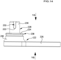
- the foot module 122 of the Fig. 5 and 6 The support bracket 108 shown is in the Fig. 13 to 16 shown individually and comprises a base plate 226 that can be placed on the clamping body 106 and a base element 228 carried by the base plate 226.
- the base element 228 comprises an anti-twist section 230, which is preferably designed exactly like the anti-twist section 218 of the coupling part 206 of the extension module 120.
- the anti-rotation section 230 has an anti-rotation groove 220 of width b running in the axial direction.
- the anti-twisting section 230 of the base element 228 is followed downwards, i.e. in the direction of the base plate 226, by a threaded section 234 of the base element 228, which is preferably designed essentially in exactly the same way as the threaded section 216 of the coupling part 206 of the extension module 120.
- the threaded portion 234 of the base element 228 has in particular an external thread 238 complementary to an internal thread 236 of the union nut 210 of the extension module 120.
- the threaded portion 234 of the base element 228 is followed downwards, i.e. towards the base plate 226, by a connecting portion 240 of the base element 228, by means of which the base element 228 can be connected - preferably detachably - to the base plate 226.
- the connecting portion 240 may have one or more threaded blind holes 242 (see Fig. 5 ), into each of which a fastening screw 244 can be screwed, which penetrates a stepped opening 246 in the base plate 226.
- the foot module 122 is mounted on the extension module 120 of the support frame 108 by inserting the anti-twist section 230 of the base element 228 of the foot module 122 into the interior 212 of the extension module 120 such that the anti-twist pin 248 on the lower part 208 of the extension module 120 engages with the anti-twist groove 232 on the anti-twist section 230 of the base element 228 of the foot module 122, whereby the foot module 122 is secured in a predetermined angular position with respect to the common longitudinal axis 126 of the extension module 120 and the foot module 122 relative to the extension module 120.
- the anti-twisting pin 248 of the extension module 120 and the anti-twisting groove 232 of the foot module 122 thus together form an anti-twisting device 250, by means of which the foot module 122 can be secured in a predetermined angular position relative to the extension module 120.
- the union nut 120 is then rotated about the longitudinal axis 126 of the extension module 120, for example by means of one of the hook wrench areas 166a or 166b of the multi-function tool 158, so that its internal thread 236 engages with the external thread 238 of the threaded portion 234 of the base element 228 of the foot module 122.
- the external thread 238 of the foot module 122 and the union nut 210 of the extension module 120 thus together form a screw connection 252, by means of which the foot module 122 can be screwed to the extension module 120.
- This screw connection 252 between the foot module 122 and the extension module 120 is designed to be compatible with the screw connection 192 between the extension module 120 and the support module 118, so that the foot module 122 can alternatively also be screwed directly to the support module 118.
- the anti-twisting device 250 between the foot module 122 and the extension module 120 is preferably designed to be compatible with the anti-twisting device 182 between the extension module 120 and the support module 118, so that the foot module 122 can also be secured directly to the support module 118 in a predetermined angular position with respect to the longitudinal axis 126 relative to the support module 118.
- the base plate 226 of the foot module 122 has one or more mounting openings 254, through which one or more mounting means 256 (see the Fig. 2 and 4 ) into a thread of a respective T-slot nut 258 (see Fig. 3 ), which is arranged in one of the T-slots 116 of the clamping body 106, in order to detachably mount the base plate 226 and thus the foot module 122 to the clamping body 106.
- Each of the mounting means 256 may comprise, for example, a threaded bolt, a nut and washer, or a mounting screw.
- Each of the mounting openings 254 is preferably formed as an elongated hole 260.
- mounting openings 254 are designed as elongated holes 260, they preferably extend along diverging longitudinal directions 262.
- the distances between adjacent mounting openings 254 become larger with increasing distance from the base element 228 of the foot module 122.
- the support module 118 is connected directly to a base element 152 without the interposition of an extension module 120, which is preferably designed exactly like the base element 228 of the foot module 122 described above, which is easily possible due to the compatibility between the screw connections 192 and 252 described above and between the anti-twist devices 182 and 250 described above.
- the Fig. 1 and 2 The support blocks 108d and 108e shown point this in the Fig. 8 to 10 shown structure, in which a support module 118 is directly combined with a base element 152.
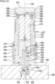
- the mounting of the support blocks 108d and 108e on the clamping body 106 is carried out by means of an adapter element 262, as shown in the sectional view of Fig. 31 is shown.
- the adapter element 262 comprises an upper threaded portion 264 provided with an external thread 266, a lower threaded portion 268 provided with an external thread 270, and a middle portion 272 connecting the upper threaded portion 264 and the lower threaded portion 268 to one another.
- the external thread 270 of the lower threaded portion 268 of the adapter element 262 engages with a complementary internal thread 274 of a T-slot nut 258 which is arranged in a T-slot 116 of the clamping body 106.
- the central portion 272 of the adapter element 262 is received in a - preferably substantially cylindrical - interior space 276 of the base element 152.
- the external thread 266 of the upper threaded portion 264 engages with an internal thread 278 of a threaded blind hole 280 which extends upward from the interior 276 of the base element 152.
- the base element 152 is thus detachably mounted on the clamping body 106.
- the support bracket 108c of the clamping arrangement 100 shown in FIG. 1 differs from the support bracket 108a described above in that the extension module 120 described above is replaced by a shorter extension module 120', which is shown in FIG. Fig. 17 to 20 is shown individually.
- This short extension module 120' differs from the long extension module 120 described above in that the sleeve part 204 is missing and instead the lower part 208 of the short extension module 120' is directly connected to a modified coupling part 206' of the extension module 120'.
- This connection can be made, for example, by pressing, gluing, welding or soldering.
- the anti-twisting section 218 and the threaded section 216 of the modified coupling part 206' are constructed in exactly the same way as the anti-twisting section 218 and the threaded section 216 of the coupling part 206 of the long extension module 120, respectively, so that the anti-twisting device 182 and the screw connection 192 of the short extension module 120' are compatible with the anti-twisting device 182 and the screw connection 192 of the long extension module 120, respectively.
- the lower part 208 of the short extension module 120' is designed exactly like the lower part 208 of the long extension module 120.
- the union nut 210 of the short extension module 120' is designed exactly like the union nut 210 of the long extension module 120.
- the short embodiment 120' of the extension module shown in the drawing is similar in terms of structure, function and method of manufacture to that shown in the Fig. 11 and 12 illustrated long embodiment 120 of the extension module, to the above description of which reference is made in this respect.
- the support frame 108b shown is composed of a support module 118 and two short extension modules 120' mounted one above the other.
- this support bracket 108b on the clamping body 106 is carried out as with the support brackets 108d and 108e by means of a base element 152 which is mounted on the lower short extension module 120'. and an adapter element 262, which connects the base element 152 to a T-slot nut 258 arranged in a T-slot 116 of the clamping body 106.
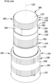
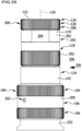
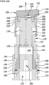
- the second embodiment of a support module shown which is referred to below as support module 118', differs from the support module 118 described above in that the external thread 136 of the threaded spindle 134 and the internal thread 138 of the base part 124 of the support module 118' are not designed as a trapezoidal thread, but preferably as a fine thread, in particular as a metric ISO fine thread according to the standard DIN 13-2 of November 1999.
- the pitch of the external thread 136 of the threaded spindle 134 and/or the pitch of the internal thread 138 of the base part 124 is at most 4 mm, in particular at most 3 mm, particularly preferably at most 2 mm.
- a fine thread offers the further advantage that it has a large core diameter, whereby the component provided with the fine thread, in particular the threaded spindle 134, is weakened little by the generation of the fine thread and thus has a high mechanical stability.
- the support module 118' in contrast to the support module 118 described above, does not comprise a lock nut 150.
- Such a lock nut 150 is not required due to the use of a fine thread.
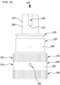
- the threaded spindle 134 in this embodiment has a thickened upper end region 282 which is provided on its outer circumference with two substantially flat actuating surfaces 284 which are diametrically opposite one another and are aligned substantially parallel to one another, so that the upper end region 282 of the threaded spindle 134 is designed as a dihedral.
- the distance between the two actuating surfaces 284 of the threaded spindle 134 corresponds to the distance a of the jaws 164 of the open-end wrench area 162 of the multi-function tool 158 (see Fig. 22 ), so that the threaded spindle 134 in this embodiment can be rotated about the longitudinal axis 126 of the support module 118' by means of the open-end wrench area 162 of the multi-function tool 158 applied to the actuating surfaces 284.
- the support element 130 on whose support surface 132 the workpiece 102 to be clamped or a clamping element 110 can be placed, is not rigidly attached to the threaded spindle 134 in this embodiment, but is designed as an angle compensation element 286, which relative to the longitudinal axis 126 of the support module 118' from the Fig. 27 shown starting position into the Fig. 28 shown angle compensation position, in which the normal direction 288 of the support surface 132 is inclined with respect to the longitudinal axis 126.
- the angle compensation element 286 is held, for example, in a force-fitting manner, in particular by a magnetic holding force, on the threaded spindle 134 serving as the angle compensation element carrier 293.
- the magnetic holding force can be generated, for example, by means of one or more magnetic elements 288 which are arranged on the upper side of the threaded spindle 134 facing the angle compensation element 286.
- one or more magnetic elements are arranged on the angle compensation element 286.
- the magnetic elements 288 are preferably designed as permanent magnets.
- the underside 290 of the angle compensation element 286 facing the threaded spindle 134 is preferably substantially spherically curved, and the upper side 292 of the threaded spindle 134 facing the angle compensation element 286 is preferably complementary to the spherical underside 290 of the angle compensation element 286 in order to enable pivoting of the angle compensation element 286 relative to the longitudinal axis 126 of the support module 118'.
- a stop element 294 which can be designed, for example, as a grub screw 296, the longitudinal axis of which is aligned parallel to the longitudinal axis 126 of the support module 118' and which is screwed into a threaded blind hole on the upper side 292 of the threaded spindle 134.
- the stop element 294 engages in a recess 298 on the underside 290 of the angle compensation element 286, the extent of which determines the maximum angle by which the angle compensation element 286 can be moved out of the Fig. 27 shown starting position can be deflected.
- the angle compensation element 286 can be provided with a corrugation 300 on its outer circumference in order to facilitate the handling of the angle compensation element 286.
- the threaded spindle 134 of the support module 118' is provided with a cover sleeve 302 which extends downwards from the upper end region 282 of the threaded spindle 134 and covers the space between the upper end region 282 of the threaded spindle 134 on the one hand and an upper edge 304 of the base part 124 on the other hand in every height position of the head part 128 of the support module 118' formed from the threaded spindle 134 and the angle compensation element 286 relative to the base part 124 of the support module 118', so that no contaminants, in particular no chips or liquid contaminants such as lubricants or coolants, can get from an external space 306 of the support module 118' to the external thread 136 of the threaded spindle 134.
- a lower end region 308 of the cover sleeve 302 slides along the outer circumference of the base part 124 when the height of the head part 128 is adjusted relative to the base part 124.
- the support module 118' differs from the support module 118 described above in that the base part 124 does not comprise an intermediate part 144, but instead the lower part 146, which is preferably designed exactly like the lower part 146 of the base part 124 of the support module 118, is connected directly to the upper part 142 of the base part 124 of the support module 118'.
- This connection can be made, for example, by pressing, gluing, welding or soldering.
- the support module 118' can be combined with one or more of the extension modules 120 or 120' and/or with a foot module 122 to form a support frame 108.
- the support module 118' can be coupled to a T-slot nut 258 arranged in a T-slot 116 of a clamping body 106 by means of the base element 152 and an adapter element 262 in engagement with the base element 152 and can thereby be releasably secured to the clamping body 106, as has been described above in connection with the first embodiment 118 of the support module.
- the second embodiment 118' corresponds in terms of structure, function and method of manufacture to the first embodiment 118 of the support module, to the above description of which reference is made in this respect.
Landscapes
- Engineering & Computer Science (AREA)
- Mechanical Engineering (AREA)
- Surgical Instruments (AREA)
- Jigs For Machine Tools (AREA)
Description
- Die vorliegende Erfindung betrifft einen modularen Abstützbock, welcher ein Abstützmodul, das ein Basisteil und ein relativ zu dem Basisteil höhenverstellbares Kopfteil umfasst, und ein Verlängerungsmodul, auf welches das Abstützmodul aufsetzbar ist, umfasst.
- Ein solcher Abstützbock wird als Bestandteil einer Spannanordnung zum Einspannen eines zu bearbeitenden Werkstücks an einer Spannfläche eines Aufspannkörpers verwendet und dient zur Abstützung des einzuspannenden Werkstücks oder eines Spannelements, beispielsweise eines Spanneisens, mittels welchem eine Spannkraft auf das einzuspannende Werkstück übertragen wird.
- Bei bekannten Abstützböcken dieser Art wird das Abstützmodul lediglich lose auf das Verlängerungsmodul aufgesteckt. Ein solcher Abstützbock ist mit geringem Aufwand herstellbar, weist aber eine unsichere und instabile Bauweise auf.
- Die
EP 0 441 437 A1 und dieDE 89 03 660 U1 offenbaren modulare Abstützböcke gemäß dem Oberbegriff von Anspruch 1. - Der vorliegenden Erfindung liegt die Aufgabe zugrunde, einen modularen Abstützbock der eingangs genannten Art zu schaffen, welcher eine höhere Sicherheit und mechanische Stabilität aufweist.
- Diese Aufgabe wird durch einen modularen Abstützbock nach Anspruch 1 gelöst.
- Eine solche Verdrehsicherung kann insbesondere eine Verdrehsicherungsnut und einen mit der Verdrehsicherungsnut in Eingriff bringbaren Verdrehsicherungszapfen umfassen.
- Grundsätzlich kann vorgesehen sein, dass die Verdrehsicherungsnut an dem Abstützmodul angeordnet ist und dass der Verdrehsicherungszapfen an dem Verlängerungsmodul angeordnet ist.
- Bei einer bevorzugten Ausgestaltung ist jedoch vorgesehen, dass die Verdrehsicherungsnut an dem Verlängerungsmodul angeordnet ist und der Verdrehsicherungszapfen an dem Abstützmodul angeordnet ist.
- Besonders günstig ist es, wenn eine weitere Verdrehsicherung vorgesehen ist, mittels welcher ein weiteres Verlängerungsmodul, ein Fußmodul oder ein Sockelelement in einer vorgegebenen Winkelposition in Bezug auf die Längsachse des Abstützbocks relativ zu dem Verlängerungsmodul sicherbar ist.
- Durch das weitere Verlängerungsmodul oder durch mehrere weitere Verlängerungsmodule kann die Gesamthöhe des modularen Abstützbocks in gewünschter Weise gewählt werden.
- Mittels eines Fußmoduls oder eines Sockelelements ist der Abstützbock in sicherer und mechanisch stabiler Weise mit einem Aufspannkörper montierbar.
- Vorzugsweise ist die weitere Verdrehsicherung kompatibel mit der ersten Verdrehsicherung, mittels welcher das erste Verlängerungsmodul in einer vorgegebenen Winkelposition in Bezug auf eine Längsachse des Abstützbocks relativ zu dem Abstützmodul sicherbar ist, ausgebildet, so dass das weitere Verlängerungsmodul, das Fußmodul oder das Sockelelement des Abstützbocks in einer vorgegebenen Winkelposition in Bezug auf die Längsachse des Abstützbocks relativ zu dem Abstützmodul direkt an dem Abstützmodul sicherbar ist.
- Auf diese Weise ist es möglich, auf das erste Verlängerungsmodul zu verzichten, wenn ein Abstützbock mit einer geringeren Gesamthöhe benötigt wird.
- Durch die Kompatibilität der Verdrehsicherungen des modularen Abstützbocks ist gewährleistet, dass die einzelnen Module des Abstützbocks, insbesondere ein oder mehrere Verlängerungsmodule, ein Fußmodul und/oder ein Sockelelement, in variabler Anzahl und in variabler Reihenfolge miteinander gekoppelt werden können, um einen modularen Abstützbock mit den gewünschten Abmessungen aufzubauen.
- Die mechanische Stabilität des modularen Abstützbocks wird dadurch erhöht, dass eine Schraubverbindung vorgesehen ist, mittels welcher das Verlängerungsmodul mit dem Abstützmodul verschraubbar ist.
- Diese Schraubverbindung umfasst ein Außengewinde und eine Überwurfmutter.
- Grundsätzlich kann vorgesehen sein, dass das Außengewinde an dem Abstützmodul und die Überwurfmutter an dem Verlängerungsmodul angeordnet ist.
- Bei einer bevorzugten Ausgestaltung der Erfindung ist jedoch vorgesehen, dass das Außengewinde an dem Verlängerungsmodul und die Überwurfmutter an dem Abstützmodul angeordnet ist.
- Besonders günstig ist es, wenn eine weitere Schraubverbindung vorgesehen ist, mittels welcher ein weiteres Verlängerungsmodul, ein Fußmodul oder ein Sockelelement mit dem Verlängerungsmodul verschraubbar ist.
- Dabei ist vorzugsweise die weitere Schraubverbindung kompatibel mit der ersten Schraubverbindung ausgebildet, mittels welcher das erste Verlängerungsmodul mit dem Abstützmodul verschraubbar ist, so dass das weitere Verlängerungsmodul, das Fußmodul oder das Sockelelement direkt mit dem Abstützmodul verschraubbar ist.
- Hierdurch ist es möglich, das Abstützmodul des modularen Abstützbocks mit einer beliebigen Anzahl von Verlängerungsmodulen und gegebenenfalls auch mit einem Fußmodul oder einem Sockelelement zu einem modularen Abstützbock zusammenzusetzen, welcher die gewünschte Höhe aufweist, wobei die Verlängerungsmodule in beliebiger Reihenfolge aufeinanderfolgen oder auch teilweise oder ganz entfallen können.
- Um eine Feineinstellung der Gesamthöhe des modularen Abstützbocks vornehmen zu können, ist es günstig, wenn das Abstützmodul eine Höhenverstellungseinrichtung für das Kopfteil umfasst, wobei die Höhenverstellungseinrichtung eine Gewindespindel und ein Innengewinde sowie optional eine Kontermutter umfasst.
- Die Gewindespindel kann insbesondere ein Trapezgewinde aufweisen, vorzugsweise ein metrisches ISO-Trapezgewinde nach der Norm DIN 103-1 vom 4. Januar 1977.
- Durch die Ausbildung des Gewindes der Gewindespindel als Trapezgewinde ist eine schnelle Einstellung der Höhe des Kopfteils relativ zu dem Basisteil des Abstützmoduls möglich.
- Die Steigung des Trapezgewindes beträgt vorzugsweise mindestens 4 mm, insbesondere mindestens 6 mm, besonders bevorzugt mindestens 7 mm.
- Alternativ hierzu kann auch vorgesehen sein, dass die Gewindespindel ein Feingewinde aufweist, insbesondere ein metrisches ISO-Feingewinde nach der Norm DIN 13-2 vom November 1999.
- Durch die Ausbildung des Gewindes der Gewindespindel als ein Feingewinde ist auch unter Belastung des Abstützmoduls eine präzise Höhenverstellung des Kopfteils relativ zu dem Basisteil des Abstützmoduls möglich.
- Die Steigung des Feingewindes beträgt vorzugsweise höchstens 4 mm, insbesondere höchstens 3 mm, besonders bevorzugt höchstens 2 mm.
- Bei einer besonderen Ausgestaltung der Erfindung ist vorgesehen, dass das Abstützmodul ein relativ zu einer Längsachse des Abstützmoduls verschwenkbares Winkelausgleichselement umfasst.
- Hierdurch ist es möglich, Abweichungen der Auflegeflächen eines einzuspannenden Werkstücks oder eines Spannelements von einer zu der Spannfläche des Aufspannkörpers parallelen Ausrichtung durch eine Verschwenkung des Winkelausgleichselements auszugleichen.
- Bei einer bevorzugten Ausgestaltung der Erfindung ist vorgesehen, dass das Abstützmodul ein Magnetelement umfasst, mittels welchem das Winkelausgleichselement in verschiedenen Winkelpositionen bezüglich der Längsachse des Abstützmoduls an einem Winkelausgleichselementträger des Abstützmoduls gehalten ist.
- Dabei kann grundsätzlich vorgesehen sein, dass ein solches Magnetelement an dem Winkelausgleichselement angeordnet ist.
- Vorzugsweise ist jedoch vorgesehen, dass das Magnetelement an dem Winkelausgleichselementträger des Abstützmoduls angeordnet ist.
- Grundsätzlich kann auch vorgesehen sein, dass ein Magnetelement an dem Winkelausgleichselement angeordnet ist und ein weiteres Element an dem Winkelausgleichselementträger des Abstützmoduls angeordnet ist.
- Das Magnetelement ist vorzugsweise als ein Dauermagnet ausgebildet.
- Zum Schutz des Gewindes der Gewindespindel vor einer Verunreinigung kann vorgesehen sein, dass das Abstützmodul eine Abdeckung, insbesondere in Form einer Abdeckhülse, umfasst, welche das Gewinde der Gewindespindel - vorzugsweise in jeder Höhenposition des Kopfteils relativ zu dem Basisteil des Abstützmoduls - gegenüber einem Außenraum des Abstützmoduls abschirmt, so dass keine Verunreinigungen, insbesondere keine Späne oder flüssige Verunreinigungen wie Schmierstoffe oder Kühlstoffe, aus dem Außenraum des Abstützmoduls zu dem Gewinde der Gewindespindel gelangen können.
- Eine solche Abdeckung des Gewindes der Gewindespindel ist insbesondere dann vorteilhaft, wenn das Gewinde der Gewindespindel als ein Feingewinde ausgebildet ist, welches sonst sehr verschmutzungs- und verschleißanfällig wäre.
- Weitere Merkmale und Vorteile der Erfindung sind Gegenstand der nachfolgenden Beschreibung und der zeichnerischen Darstellung von Ausführungsbeispielen.
- In den Zeichnungen zeigen:
- Fig. 1
- eine perspektivische Darstellung einer Spannanordnung, mittels welcher ein Werkstück an einer Spannfläche eines Aufspannkörpers eingespannt ist;
- Fig. 2
- eine Seitenansicht der Spannanordnung, des Werkstücks und des Aufspannkörpers aus
Fig. 1 ; - Fig. 3
- eine Vorderansicht der Spannanordnung, des Werkstücks und des Aufspannkörpers aus den
Fig. 1 und2 , mit der Blickrichtung in Richtung des Pfeiles 3 inFig. 2 ; - Fig. 4
- eine Draufsicht auf die Spannanordnung, das Werkstück und den Aufspannkörper aus den
Fig. 1 bis 3 von oben, mit der Blickrichtung in Richtung des Pfeiles 4 inFig. 2 ; - Fig. 5
- einen Längsschnitt durch einen modularen Abstützbock der Spannanordnung aus den
Fig. 1 bis 4 , welcher inFig. 2 ganz rechts dargestellt ist, geschnitten parallel zur Zeichenebene vonFig. 2 ; - Fig. 6
- einen Längsschnitt durch den modularen Abstützbock aus
Fig. 5 , geschnitten längs der Linie 6 - 6 inFig. 5 ; - Fig. 7
- eine perspektivische Darstellung eines Abstützmoduls des modularen Abstützbocks aus den
Fig. 5 und6 ; - Fig. 8
- eine Vorderansicht des Abstützmoduls aus
Fig. 7 ; - Fig. 9
- eine Seitenansicht des Abstützmoduls aus den
Fig. 7 und8 , mit der Blickrichtung in Richtung des Pfeiles 9 inFig. 8 ; - Fig. 10
- einen Längsschnitt durch das Abstützmodul aus den
Fig. 7 bis 9 ; - Fig. 11
- eine Vorderansicht eines Verlängerungsmoduls des modularen Abstützbocks aus den
Fig. 5 und6 ; - Fig. 12
- einen Längsschnitt durch das Verlängerungsmodul aus
Fig. 11 , geschnitten senkrecht zur Zeichenebene derFig. 11 ; - Fig. 13
- eine perspektivische Darstellung eines Fußmoduls des modularen Abstützbocks aus den
Fig. 5 und6 ; - Fig. 14
- eine Seitenansicht des Fußmoduls aus
Fig. 13 ; - Fig. 15
- eine Draufsicht auf das Fußmodul aus den
Fig. 13 und14 , mit der Blickrichtung in Richtung des Pfeiles 15 inFig. 14 ; - Fig. 16
- eine Draufsicht von unten auf das Fußmodul aus den
Fig. 13 bis 15 , mit der Blickrichtung in Richtung des Pfeiles 16 inFig. 14 ; - Fig. 17
- eine perspektivische Darstellung einer weiteren Ausführungsform eines Verlängerungsmoduls eines modularen Abstützbocks;
- Fig. 18
- eine Vorderansicht des Verlängerungsmoduls aus
Fig. 17 ; - Fig. 19
- eine Draufsicht von oben auf das Verlängerungsmodul aus den
Fig. 17 und18 , mit der Blickrichtung in Richtung des Pfeiles 19 inFig. 18 ; - Fig. 20
- einen Längsschnitt durch das Verlängerungsmodul aus den
Fig. 17 bis 19 , geschnitten längs der Linie 20 - 20 inFig. 19 ; - Fig. 21
- eine perspektivische Darstellung eines Multifunktionswerkzeugs für die Montage eines modularen Abstützbocks;
- Fig. 22
- eine Draufsicht auf das Multifunktionswerkzeug aus
Fig. 21 von oben; - Fig. 23
- eine Seitenansicht des Multifunktionswerkzeugs aus den
Fig. 21 und22 , mit der Blickrichtung in Richtung des Pfeiles 23 inFig. 22 ; - Fig. 24
- eine perspektivische Darstellung einer alternativen Ausführungsform eines Abstützmoduls, wobei das Abstützmodul eine Höhenverstelleinrichtung für ein Kopfteil des Abstützmoduls umfasst, welche eine Gewindespindel umfasst, die ein Feingewinde aufweist, und wobei das Abstützmodul auf ein Sockelelement aufgesetzt ist;
- Fig. 25
- eine Vorderansicht des Abstützmoduls aus
Fig. 24 ; - Fig. 26
- eine Seitenansicht des Abstützmoduls aus den
Fig. 24 und25 , mit der Blickrichtung in Richtung des Pfeiles 26 inFig. 25 ; - Fig. 27
- einen Längsschnitt durch das Abstützmodul aus den
Fig. 24 bis 26 , wobei ein Winkelausgleichselement des Abstützmoduls sich in seiner Ausgangsposition befindet, in welcher eine Auflagefläche des Winkelausgleichselements senkrecht zu einer Längsachse des Abstützmoduls ausgerichtet ist; - Fig. 28
- einen der
Fig. 27 entsprechenden Längsschnitt durch das Abstützmodul aus denFig. 24 bis 26 , wobei ein Kopfteil des Abstützmoduls relativ zu einem Basisteil des Abstützmoduls längs der Längsachse des Abstützmoduls nach oben bewegt worden ist und das Winkelausgleichselement aus seiner inFig. 27 dargestellten Ausgangsposition in eine Winkelausgleichsposition ausgelenkt worden ist, in welcher die Normalenrichtung der Auflagefläche des Winkelausgleichselements gegenüber der Längsachse des Abstützmoduls geneigt ist; - Fig. 29
- eine perspektivische Darstellung des Abstützmoduls und des Fußmoduls aus den
Fig. 24 bis 28 , wobei das Sockelelement mittels eines Adapters mit einem T-Nutenstein in einer T-Nut eines Aufspannkörpers verbunden ist; - Fig. 30
- eine Vorderansicht des Abstützmoduls, des Sockelelements und des Aufspannkörpers aus
Fig. 29 ; und - Fig. 31
- einen Längsschnitt durch das Abstützmodul, das Sockelelement, den Adapter, den T-Nutenstein und den Aufspannkörper aus den
Fig. 29 und30 , geschnitten parallel zur Zeichenebene derFig. 30 . - Gleiche oder funktional äquivalente Elemente sind in allen Figuren mit denselben Bezugszeichen bezeichnet.
- Eine in den
Fig. 1 bis 4 dargestellte, als Ganzes mit 100 bezeichnete Spannanordnung dient zum Einspannen eines Werkstücks 102 an einer Spannfläche 104 eines Aufspannkörpers 106. - Der Aufspannkörper 106 kann beispielsweise als ein Maschinentisch oder als eine Spannpalette ausgebildet sein.
- Wie am besten aus der Seitenansicht der
Fig. 2 zu ersehen ist, umfasst die Spannanordnung 100 mehrere, beispielsweise zwei, Abstützböcke 108, nämlich einen ersten, inFig. 2 ganz rechts dargestellten, Abstützbock 108a und einen zweiten inFig. 2 ganz links dargestellten, Abstützbock 108b, welche jeweils ein Spannelement 110 der Spannanordnung 100 abstützen. - Jedes der Spannelemente, welche beispielsweise als ein Spanneisen ausgebildet sind, liegt an einer der Spannfläche 104 abgewandten Seite des Werkstücks 102 an dem einzuspannenden Werkstück 102 an und wird mittels jeweils einer Zugstange 112 zur Spannfläche 104 hin gezogen.
- Dabei wird die Spannkraft mittels jeweils einer Spannmutter 114, die in Eingriff mit einem Gewinde der jeweiligen Zugstange 112 steht, von der Zugstange 112 auf das Spannelement 110 übertragen.
- Ein der Spannmutter 114 abgewandtes Ende der Zugstange 112 steht in Eingriff mit jeweils einem T-Nutenstein, der in einer T-Nut 116 des Aufspannkörpers 106 angeordnet ist.
- Ferner umfasst die Spannanordnung 100 mehrere, beispielsweise drei, Abstützböcke 108, welche das Werkstück 102 selbst abstützen, nämlich einen in
Fig. 2 rechts von dem Abstützbock 108b angeordneten Abstützbock 108c, einen inFig. 2 rechts von dem Abstützbock 108c angeordneten Abstützbock 108d und einen inFig. 2 rechts von dem Abstützbock 108d und links von dem Abstützbock 108a angeordneten Abstützbock 108e. - Im Folgenden wird der Aufbau des in
Fig. 2 ganz rechts dargestellten Abstützbocks 108a näher erläutert werden, welcher in denFig. 5 und6 einzeln im Längsschnitt dargestellt ist. - Der in den
Fig. 5 und6 einzeln dargestellte modulare Abstützbock 108 umfasst ein Abstützmodul 118, ein Verlängerungsmodul 120 und ein Fußmodul 122. - Das Abstützmodul 118 umfasst ein Basisteil 124 und ein relativ zu dem Basisteil 124 längs einer Längsachse 126 des Abstützmoduls 118 und des Abstützbocks 108 höhenverstellbares Kopfteil 128.
- Das Kopfteil 128 umfasst ein Auflageelement 130, welches eine Auflagefläche 132 zum Auflegen eines Werkstücks 102 oder eines Spannelements 110 auf das Abstützmodul 118 aufweist.
- Das Kopfteil 128 ist, vorzugsweise lösbar, an einer Gewindespindel 134 festgelegt.
- Die Festlegung des Kopfteils an der Gewindespindel 134 kann beispielsweise mittels Verschraubung erfolgen.
- Das Außengewinde 136 der Gewindespindel 134 greift in ein hierzu komplementär ausgebildetes Innengewinde 138 des Basisteils 124 des Abstützmoduls 118 ein.
- Das Außengewinde 136 der Gewindespindel 134 und das Innengewinde 138 des Basisteils 124 sind vorzugsweise jeweils als ein Trapezgewinde ausgebildet, vorzugsweise als ein metrisches ISO-Trapezgewinde nach der Norm DIN 103-1 vom 4. Januar 1977.
- Durch die Ausbildung dieser Gewinde als Trapezgewinde ist eine schnelle Einstellung der Höhe des Kopfteils 128 relativ zu dem Basisteil 124 gewährleistet.
- Vorzugsweise beträgt die Steigung des Außengewindes 136 der Gewindespindel 134 und/oder die Steigung des Innengewindes 138 des Basisteils 124 mindestens 4 mm, insbesondere mindestens 6 mm, besonders bevorzugt mindestens 7 mm.
- Das Basisteil 124 ist als eine im Wesentlichen hohlzylindrische Hülse 140 ausgebildet und umfasst mehrere Teile, beispielsweise ein Oberteil 142, an dem das Innengewinde 138 ausgebildet ist, ein auf der dem Kopfteil 128 abgewandten Seite des Oberteils 142 angeordnetes Zwischenteil 144 und ein auf der dem Oberteil 142 abgewandten Seite des Zwischenteils 144 angeordnete Unterteil 146.
- Das Oberteil 142, das Zwischenteil 144 und das Unterteil 146 des Basisteils 124 umschließen zusammen einen Innenraum 148 des Basisteils 124, welcher einen unteren Endbereich der Gewindespindel 134 aufnimmt, wenn das Kopfteil 128 durch Eindrehen des Außengewindes 136 der Gewindespindel 134 in das Innengewinde 138 des Basisteils 124 längs der Längsachse 126 des Abstützmoduls 118 nach unten bewegt wird.
- Wenn das Kopfteil 128 die gewünschte Höhe erreicht hat, wird es in dieser Position durch Anziehen einer Kontermutter 150 gegen das Basisteil 124 gesichert.
- Die Gewindespindel 154, das Innengewinde 138 des Basisteils 124 und die Kontermutter 150 bilden somit Bestandteile einer Höhenverstellungseinrichtung 157 des Abstützmoduls 118, mittels welcher die Höhenposition des Kopfteils 128 relativ zu dem Basisteil 124 einstellbar ist.
- Wie am besten aus den
Fig. 8 und9 zu ersehen ist, die das Abstützmodul 118 zusammen mit einem Sockelelement 152 zeigen, welches das Abstützmodul 118 trägt, weist die Kontermutter 150 zwei einander diametral gegenüberliegende, im Wesentlichen ebene und parallel zueinander ausgerichtete Betätigungsflächen 154 auf, an denen ein geeignetes Werkzeug angreifen kann, um die Kontermutter 150, welche in Eingriff mit dem Außengewinde 136 der Gewindespindel 134 steht, um die Längsachse 126 des Abstützmoduls 118 zu drehen. - Die Kontermutter 150 ist somit als ein Zweiflach ausgebildet.
- Zwischen den Betätigungsflächen 154 ist die Kontermutter 150 längs ihres Umfangs mit einer Riffelung 156 versehen.
- Die Betätigung der Kontermutter 150 kann beispielsweise mittels eines in den
Fig. 21 bis 23 dargestellten Multifunktionswerkzeugs 158 erfolgen. - Ein erster Endbereich 160a des Multifunktionswerkzeugs 158 ist als ein Gabelschlüsselbereich 162 ausgebildet. Der Abstand a zwischen den beiden Backen 164 des Gabelschlüsselbereichs 162 entspricht dem Abstand zwischen den beiden Betätigungsflächen 154 der Kontermutter 150, so dass der Gabelschlüsselbereich 162 an den Betätigungsflächen 154 der Kontermutter 150 angesetzt werden kann, um die Kontermutter 150 um die Längsachse 126 des Abstützmoduls 118 zu drehen.
- Ein dem ersten Endbereich 160a abgewandter zweiter Endbereich 160b des Multifunktionswerkzeugs 158 umfasst zwei Hakenschlüsselbereiche 166a und 166b.
- Jeder der Hakenschlüsselbereiche 166a, 166b umfasst einen Bogenbereich 168, welcher komplementär zu einem Kreisscheibensegment mit dem Durchmesser D ausgebildet ist, und einen an einem Endbereich des Bogenabschnittes 168 angeordneten Zapfen 170.
- Diese Hakenschlüsselbereiche 166a, 166b können dazu verwendet werden, das Abstützmodul 118 mit dem Verlängerungsmodul 120 und/oder das Verlängerungsmodul 120 mit dem Fußmodul 122 des Abstützbocks 108 zu verschrauben, was später noch näher erläutert werden wird.
- Wie am besten aus den
Fig. 21 und22 zu ersehen ist, sind der erste Endbereich 160a und der zweite Endbereich 160b des Multifunktionswerkzeugs 158 durch eine Abkröpfung 172 miteinander verbunden, so dass der zweite Endbereich 160b um die Strecke s gegenüber dem ersten Endbereich 160a versetzt ist. - Durch diesen Versatz s ist es möglich, das Multifunktionswerkzeug 158 auch dann einzusetzen, wenn die Platzverhältnisse um den Abstützbock 108 herum beengt sind.
- Ferner kann das Multifunktionswerkzeug 158 eine oder mehrere, beispielsweise zwei, Durchtrittsöffnungen 174 aufweisen, welche es ermöglichen, das Multifunktionswerkzeug 158 zur Lagerung an einem Stift oder an einem Haken einzuhängen.
- Nach dem Anziehen der Kontermutter 150 gegen das Basisteil 124 des Abstützmoduls 118 ist das Kopfteil 128 in seiner Höhenposition relativ zu dem Basisteil 124 gesichert (siehe
Fig. 5 und6 ). - Das Innengewinde 138 des Basisteils 124 ist an einem Gewindeloch ausgebildet, das sich von einer oberen Stirnfläche 176 des Oberteils 142 des Basisteils 124 längs der Längsachse 126 nach unten erstreckt und im Innenraum 148 des Basisteils 124 mündet.
- Eine an dem unteren Ende der Gewindespindel 134 angeordnete Anschlagscheibe 178 verhindert, dass die Gewindespindel 134 bei der Höhenverstellung des Kopfteils 128 relativ zu dem Basisteil 124 aus dem Innengewinde 138 des Basisteils 124 herausgedreht wird.
- Das Oberteil 142 und das Zwischenteil 144 des Basisteils 124 sind vorzugsweise unlösbar miteinander verbunden, beispielsweise durch Verpressung, durch Verklebung, durch Verschweißung oder durch Verlötung.
- Das Unterteil 146 und das Zwischenteil 144 des Basisteils 124 sind vorzugsweise unlösbar miteinander verbunden, beispielsweise durch Verpressung, durch Verklebung, durch Verschweißung oder durch Verlötung.
- An dem Unterteil 146 des Basisteils 124 ist ein radial zu der Längsachse 126 in den Innenraum 148 des Basisteils 124 vorstehender Verdrehsicherungszapfen 180 angeordnet, der einen Teil einer Verdrehsicherung 182 bildet, welche das Verlängerungsmodul 120 in einer vorgegebenen Winkelposition relativ zu dem Abstützmodul 118 (in Bezug auf die gemeinsame Längsachse des Abstützmoduls 118, des Verlängerungsmoduls 120 und des Abstützbocks 108) sichert.
- Ferner ist am unteren Ende des Basisteils 124 eine Überwurfmutter 184 angeordnet, welche einen Teil des Zwischenteils 144 und einen Teil des Unterteils 146 des Basisteils 124 überdeckt und nach unten über das untere Ende des Unterteils 146 des Basisteils 124 übersteht. In diesem überstehenden Bereich ist die Überwurfmutter 184 mit einem Innengewinde 186 versehen.
- Oberhalb des Innengewindes 186 ist die Überwurfmutter 184 mit einem Ringbund 188 versehen, welcher radial nach innen vorsteht und in einen Zwischenraum zwischen einem unteren Ende des Zwischenteils 144 des Basisteils 124 einerseits und einem verdickten unteren Endbereich 190 des Unterteils 146 des Basisteils 124 andererseits eingreift, so dass die Überwurfmutter 184 unverlierbar, aber längs der Längsachse 126 relativ zu dem Basisteil 124 verschiebbar an dem Basisteil 124 gehalten ist.
- Die Überwurfmutter 184 bildet einen Bestandteil einer Schraubverbindung 192, mittels welcher das Abstützmodul 118 mit dem Verlängerungsmodul 120 des Abstützbocks 108 verschraubbar ist.
- Wie am besten aus den
Fig. 7 bis 9 zu ersehen ist, weist die Überwurfmutter 184 an ihrem äußeren Umfang einen dem Kopfteil 128 des Abstützmoduls 118 zugewandten oberen geriffelten Bereich 194, einen dem Kopfteil 128 abgewandten unteren geriffelten Bereich 196 und einen zwischen dem oberen geriffelten Bereich 194 und dem unteren geriffelten Bereich 196 angeordneten Betätigungsbereich 198 auf. - Der Betätigungsbereich 198 weist eine im Wesentlichen glatte zylindrische Oberfläche 200 mit einem Durchmesser D auf.
- Der Durchmesser D der glatten Oberfläche 200 des Betätigungsbereichs 198 der Überwurfmutter 184 entspricht dem Durchmesser D der Bogenabschnitte 168 der Hakenschlüsselbereiche 166a und 166b des in den
Fig. 21 bis 23 dargestellten Multifunktionswerkzeugs 158. - Jeder der Hakenschlüsselbereiche 166a, 166b des Multifunktionswerkzeugs 158 kann daher in Eingriff mit der Überwurfmutter 184 gebracht werden, indem der Zapfen 170 des jeweiligen Hakenschlüsselbereichs 166a beziehungsweise 166b in eine hierzu komplementär ausgebildete Ausnehmung 202, die in dem Betätigungsbereich 198 der Überwurfmutter 184 angeordnet ist, eingesetzt wird und der an den Zapfen 170 angrenzende Bodenabschnitt 168 des jeweiligen Hakenschlüsselbereichs 166a, 166b an die glatte Oberfläche 200 des Betätigungsbereichs 198 angelegt wird.
- Nachdem der jeweilige Hakenschlüsselbereich 166a beziehungsweise 166b in Eingriff mit dem Betätigungsbereich 198 der Überwurfmutter 184 gebracht worden ist, kann die Überwurfmutter 184 mittels des Multifunktionswerkzeugs 158 um die Längsachse 126 des Abstützmoduls 118 gedreht werden, um eine Verschraubung des Abstützmoduls 118 mit dem Verlängerungsmodul 120 zu bewirken, was nachstehend noch näher erläutert werden wird.
- Beide Hakenschlüsselbereiche 166a und 166b können jeweils in zwei verschiedenen Orientierungen in Bezug auf die Ausnehmung 202 des Betätigungsbereichs 198 an den Betätigungsbereich 198 angelegt werden. Die Auswahl des anzulegenden Hakenschlüsselbereichs 166a oder 166b und die Auswahl der Orientierung, in welcher der jeweils ausgewählte Hakenschlüsselbereich 166a oder 166b an den Betätigungsbereich 198 der Überwurfmutter 184 angelegt wird, wird unter Berücksichtigung der Abkröpfung 172 des Multifunktionswerkzeugs 158 in Abhängigkeit von den Platzverhältnissen in der Umgebung des zu montierenden Abstützbocks 108 ausgewählt.
- Das mit dem vorstehend beschriebenen Abstützmodul 118 zu koppelnde Verlängerungsmodul 120 ist einzeln in den
Fig. 11 und12 dargestellt. - Das Verlängerungsmodul 120 umfasst ein im Wesentlichen hohlzylindrisch ausgebildetes Hülsenteil 204, ein an einem oberen Ende des Hülsenteils 204 angeordnetes Kopplungsteil 206, ein an einem unteren Ende des Hülsenteils 204 angeordnetes Unterteil 208, welches vorzugsweise genau so aufgebaut ist wie das Unterteil 146 des Abstützmoduls 118, und eine das Hülsenteil 204 und das Unterteil 208 des Verlängerungsmoduls 120 teilweise überdeckende Überwurfmutter 210, welche vorzugsweise genau so ausgebildet ist wie die Überwurfmutter 184 des Abstützmoduls 118 und somit in derselben Weise wie die Überwurfmutter 184 des Abstützmoduls 118 mittels der Hakenschlüsselbereiche 166a, 166b des Multifunktionswerkzeugs 158 betätigt werden kann.
- Das Hülsenteil 204 und das Unterteil 208 des Verlängerungsmoduls 120 umschließen gemeinsam einen Innenraum 212 des Verlängerungsmoduls 120.
- Der Innenraum 212 wird an seinem oberen Ende durch das Kopplungsteil 206 verschlossen, welches vorzugsweise in einen oberen Endbereich des Hülsenteils 204 eingesetzt ist.
- Das Kopplungsteil 206 ist vorzugsweise unverlierbar mit dem Hülsenteil 204 verbunden, beispielsweise durch Verpressung, durch Verklebung, durch Verschweißung oder durch Verlötung.
- Das Kopplungsteil 206 umfasst einen in das Hülsenteil 204 eingesetzten Halteabschnitt 214, einen sich nach oben an den Halteabschnitt 214 anschließenden Gewindeabschnitt 216, welcher einen größeren Außendurchmesser aufweist als der Halteabschnitt 214, und einen auf der dem Halteabschnitt 214 abgewandten Seite des Gewindeabschnitts 216 angeordneten Verdrehsicherungsabschnitt 218, welcher einen kleineren Außendurchmesser aufweist als der Gewindeabschnitt 216.
- Der Verdrehsicherungsabschnitt 218 weist an seinem Umfang eine in Axialrichtung, das heißt parallel zur Längsachse 126 des Verlängerungsmoduls 120, verlaufende Verdrehsicherungsnut 220 auf, deren Nutbreite b im Wesentlichen dem Durchmesser des Verdrehsicherungszapfens 180 des Abstützmoduls 118 entspricht.
- Bei der Montage des Abstützbocks 108 wird der Verdrehsicherungsabschnitt 218 des Kopplungsteils 206 des Verlängerungsmoduls 120 so in den Innenraum 148 des Abstützmoduls 118 eingeführt, dass der Verdrehsicherungszapfen 180 des Abstützmoduls 118 in Eingriff mit der Verdrehsicherungsnut 220 des Verlängerungsmoduls 120 kommt.
- Wenn der Verdrehsicherungsabschnitt 218 vollständig in den Innenraum 148 des Abstützmoduls 118 eingeführt ist, liegt der Verdrehsicherungszapfen 180 des Abstützmoduls 118 vorzugsweise an einem unteren Rand 222 der Verdrehsicherungsnut 220 an.
- In diesem Zustand ist das Verlängerungsmodul 120 mittels der durch den Verdrehsicherungszapfen 180 des Abstützmoduls 118 und die Verdrehsicherungsnut 220 des Verlängerungsmoduls 120 gebildete Verdrehsicherung 182 in einer vorgegebenen Winkelposition in Bezug auf die gemeinsame Längsachse 126 des Abstützmoduls 118 und des Verlängerungsmoduls 120 relativ zu dem Abstützmodul 118 gesichert.
- In dieser Winkelposition ist das Verlängerungsmodul 120 lösbar mit dem Abstützmodul 118 verbindbar mittels der Schraubverbindung 192, welche zusätzlich zu der Überwurfmutter 184 des Abstützmoduls 118 ein zu dem Innengewinde 186 der Überwurfmutter 184 komplementäres Außengewinde 224 am äußeren Umfang des Gewindeabschnitts 216 des Kopplungsteils 206 des Verlängerungsmoduls 120 umfasst.
- Durch eine Drehung der Überwurfmutter 184 um die Längsachse 126 des Abstützmoduls 118 und des Verlängerungsmoduls 120, beispielsweise mittels eines der Hakenschlüsselbereiche 166a oder 166b des Multifunktionswerkzeugs 158, ist die Überwurfmutter 184 des Abstützmoduls 118 auf das Außengewinde 224 des Verlängerungsmoduls 120 aufschraubbar, um das Verlängerungsmodul 120 mit dem Abstützmodul 118 zu verschrauben.
- Das Fußmodul 122 des in den
Fig. 5 und6 dargestellten Abstützbocks 108 ist in denFig. 13 bis 16 einzeln dargestellt und umfasst eine auf den Aufspannkörper 106 auflegbare Basisplatte 226 sowie ein von der Basisplatte 226 getragenes Sockelelement 228. - Das Sockelelement 228 umfasst einen Verdrehsicherungsabschnitt 230, welcher vorzugsweise genau so ausgebildet ist wie der Verdrehsicherungsabschnitt 218 des Kopplungsteils 206 des Verlängerungsmoduls 120.
- Der Verdrehsicherungsabschnitt 230 weist eine in axialer Richtung verlaufende Verdrehsicherungsnut 220 der Breite b auf.
- An den Verdrehsicherungsabschnitt 230 des Sockelelements 228 schließt sich nach unten, das heißt in Richtung auf die Basisplatte 226 hin, ein Gewindeabschnitt 234 des Sockelelements 228 an, welcher vorzugsweise im Wesentlichen genau so ausgebildet ist wie der Gewindeabschnitt 216 des Kopplungsteils 206 des Verlängerungsmoduls 120.
- Der Gewindeabschnitt 234 des Sockelelements 228 weist insbesondere ein zu einem Innengewinde 236 der Überwurfmutter 210 des Verlängerungsmoduls 120 komplementäres Außengewinde 238 auf.
- An den Gewindeabschnitt 234 des Sockelelements 228 schließt sich nach unten, das heißt zur Basisplatte 226 hin, ein Verbindungsabschnitt 240 des Sockelelements 228 an, mittels welchem das Sockelelement 228 - vorzugsweise lösbar - mit der Basisplatte 226 verbindbar ist.
- Zu diesem Zweck kann der Verbindungsabschnitt 240 eines oder mehrere Gewindesacklöcher 242 (siehe
Fig. 5 ) aufweisen, in welche jeweils eine Befestigungsschraube 244 einschraubbar ist, die eine gestufte Durchtrittsöffnung 246 in der Basisplatte 226 durchsetzt. - Die Montage des Fußmoduls 122 an dem Verlängerungsmodul 120 des Abstützbocks 108 erfolgt dadurch, dass der Verdrehsicherungsabschnitt 230 des Sockelelements 228 des Fußmoduls 122 so in den Innenraum 212 des Verlängerungsmoduls 120 eingeführt wird, dass der Verdrehsicherungszapfen 248 am Unterteil 208 des Verlängerungsmoduls 120 in Eingriff mit der Verdrehsicherungsnut 232 am Verdrehsicherungsabschnitt 230 des Sockelelements 228 des Fußmoduls 122 kommt, wodurch das Fußmodul 122 in einer vorgegebenen Winkelposition bezogen auf die gemeinsame Längsachse 126 des Verlängerungsmoduls 120 und des Fußmoduls 122 relativ zu dem Verlängerungsmodul 120 gesichert ist.
- Der Verdrehsicherungszapfen 248 des Verlängerungsmoduls 120 und die Verdrehsicherungsnut 232 des Fußmoduls 122 bilden somit zusammen eine Verdrehsicherung 250, mittels welcher das Fußmodul 122 in einer vorgegebenen Winkelposition relativ zu dem Verlängerungsmodul 120 sicherbar ist.
- Anschließend wird die Überwurfmutter 120, beispielsweise mittels eines der Hakenschlüsselbereiche 166a oder 166b des Multifunktionswerkzeugs 158, so um die Längsachse 126 des Verlängerungsmoduls 120 gedreht, dass deren Innengewinde 236 in Eingriff mit dem Außengewinde 238 des Gewindeabschnitts 234 des Sockelelements 228 des Fußmoduls 122 kommt.
- Das Außengewinde 238 des Fußmoduls 122 und die Überwurfmutter 210 des Verlängerungsmoduls 120 bilden somit zusammen eine Schraubverbindung 252, mittels welcher das Fußmodul 122 mit dem Verlängerungsmodul 120 verschraubbar ist.
- Diese Schraubverbindung 252 zwischen dem Fußmodul 122 und dem Verlängerungsmodul 120 ist kompatibel mit der Schraubverbindung 192 zwischen dem Verlängerungsmodul 120 und dem Abstützmodul 118 ausgebildet, so dass das Fußmodul 122 alternativ auch direkt mit dem Abstützmodul 118 verschraubbar ist.
- Ebenso ist die Verdrehsicherung 250 zwischen dem Fußmodul 122 und dem Verlängerungsmodul 120 vorzugsweise kompatibel mit der Verdrehsicherung 182 zwischen dem Verlängerungsmodul 120 und dem Abstützmodul 118 ausgebildet, so dass das Fußmodul 122 auch direkt an dem Abstützmodul 118 in einer vorgegebenen Winkelposition bezüglich der Längsachse 126 relativ zu dem Abstützmodul 118 sicherbar ist.
- Wie am besten aus den
Fig. 2 ,4 ,13 und15 zu ersehen ist, weist die Basisplatte 226 des Fußmoduls 122 eine oder mehrere Montage-Durchtrittsöffnungen 254 auf, durch welche sich jeweils eine oder mehrere Montagemittel 256 (siehe dieFig. 2 und4 ) bis in ein Gewinde eines jeweils zugeordneten T-Nutensteins 258 (sieheFig. 3 ), welcher in einer der T-Nuten 116 des Aufspannkörpers 106 angeordnet ist, hinein erstrecken können, um so die Basisplatte 226 und damit das Fußmodul 122 lösbar an dem Aufspannkörper 106 zu montieren. - Jedes der Montagemittel 256 kann beispielsweise einen Gewindebolzen, eine Mutter und eine Unterlegscheibe oder eine Montageschraube umfassen.
- Jede der Montage-Durchtrittsöffnungen 254 ist vorzugsweise als ein Langloch 260 ausgebildet.
- Wenn mehrere Montage-Durchtrittsöffnungen 254 als Langlöcher 260 ausgebildet sind, so erstrecken sich diese vorzugsweise längs divergierender Längsrichtungen 262.
- Insbesondere kann vorgesehen sein, dass die Abstände zwischen einander benachbarten Montage-Durchtrittsöffnungen 254 mit wachsendem Abstand von dem Sockelelement 228 des Fußmoduls 122 größer werden.
- In der in den
Fig. 8 bis 10 dargestellten Konfiguration ist das Abstützmodul 118 ohne Zwischenschaltung eines Verlängerungsmoduls 120 unmittelbar mit einem Sockelelement 152 verbunden, das vorzugsweise genau so ausgebildet ist wie das Sockelelement 228 des vorstehend beschriebenen Fußmoduls 122, was aufgrund der Kompatibilität zwischen den vorstehend beschriebenen Schraubverbindungen 192 und 252 sowie zwischen den vorstehend beschriebenen Verdrehsicherungen 182 und 250 ohne weiteres möglich ist. - Die in den
Fig. 1 und2 dargestellten Abstützböcke 108d und 108e weisen diesen in denFig. 8 bis 10 dargestellten Aufbau auf, bei welchem ein Abstützmodul 118 direkt mit einem Sockelelement 152 kombiniert ist. - Die Montage der Abstützböcke 108d und 108e an dem Aufspannkörper 106 erfolgt dabei mittels eines Adapterelements 262, wie es in der Schnittdarstellung von
Fig. 31 dargestellt ist. - Das Adapterelement 262 umfasst einen oberen Gewindeabschnitt 264, der mit einem Außengewinde 266 versehen ist, einen unteren Gewindeabschnitt 268, der mit einem Außengewinde 270 versehen ist, und einen den oberen Gewindeabschnitt 264 und den unteren Gewindeabschnitt 268 miteinander verbindenden Mittelabschnitt 272.
- Im am Aufspannkörper 106 montierten Zustand steht das Außengewinde 270 des unteren Gewindeabschnitts 268 des Adapterelements 262 in Eingriff mit einem hierzu komplementär ausgebildeten Innengewinde 274 eines T-Nutensteins 258, der in einer T-Nut 116 des Aufspannkörpers 106 angeordnet ist.
- In diesem montierten Zustand ist der Mittelabschnitt 272 des Adapterelements 262 in einem - vorzugsweise im Wesentlichen zylindrischen - Innenraum 276 des Sockelelements 152 aufgenommen.
- Ferner steht in diesem montierten Zustand das Außengewinde 266 des oberen Gewindeabschnitts 264 in Eingriff mit einem Innengewinde 278 eines Gewindesacklochs 280, welches sich von dem Innenraum 276 des Sockelelements 152 aus nach oben erstreckt.
- Mittels des Adapterelements 262 ist somit das Sockelelement 152 lösbar an dem Aufspannkörper 106 montiert.
- Der in den
Fig. 1 und2 dargestellte Abstützbock 108c der Spannanordnung 100 unterscheidet sich von dem vorstehend beschriebenen Abstützbock 108a dadurch, dass das vorstehend beschriebene Verlängerungsmodul 120 durch ein kürzeres Verlängerungsmodul 120' ersetzt ist, welches in denFig. 17 bis 20 einzeln dargestellt ist. - Dieses kurze Verlängerungsmodul 120' unterscheidet sich von dem vorstehend beschriebenen langen Verlängerungsmodul 120 dadurch, dass das Hülsenteil 204 fehlt und stattdessen das Unterteil 208 des kurzen Verlängerungsmoduls 120' direkt mit einem modifizierten Kopplungsteil 206' des Verlängerungsmoduls 120' verbunden ist.
- Diese Verbindung kann beispielsweise durch Verpressung, durch Verklebung, durch Verschweißung oder durch Verlötung hergestellt sein.
- Der Verdrehsicherungsabschnitt 218 und der Gewindeabschnitt 216 des modifizierten Kopplungsteils 206' sind genau so aufgebaut wie der Verdrehsicherungsabschnitt 218 beziehungsweise der Gewindeabschnitt 216 des Kopplungsteils 206 des langen Verlängerungsmoduls 120, so dass die Verdrehsicherung 182 und die Schraubverbindung 192 des kurzen Verlängerungsmoduls 120' kompatibel sind mit der Verdrehsicherung 182 beziehungsweise mit der Schraubverbindung 192 des langen Verlängerungsmoduls 120.
- Das Unterteil 208 des kurzen Verlängerungsmoduls 120' ist genau so ausgebildet wie das Unterteil 208 des langen Verlängerungsmoduls 120.
- Die Überwurfmutter 210 des kurzen Verlängerungsmoduls 120' ist genau so ausgebildet wie die Überwurfmutter 210 des langen Verlängerungsmoduls 120.
- Im Übrigen stimmt die in den
Fig. 17 bis 20 dargestellte kurze Ausführungsform 120' des Verlängerungsmoduls hinsichtlich Aufbau, Funktion und Herstellungsweise mit der in denFig. 11 und12 dargestellten langen Ausführungsform 120 des Verlängerungsmoduls überein, auf deren vorstehende Beschreibung insoweit Bezug genommen wird. - Der in den
Fig. 1 und2 dargestellte Abstützbock 108b ist aus einem Abstützmodul 118 und zwei übereinander montierten kurzen Verlängerungsmodulen 120' zusammengesetzt. - Die Montage dieses Abstützbocks 108b an dem Aufspannkörper 106 erfolgt wie bei den Abstützbocken 108d und 108e mittels jeweils eines Sockelelements 152, das an dem unteren kurzen Verlängerungsmodul 120' montiert ist, und eines Adapterelements 262, welches das Sockelelement 152 mit einem in einer T-Nut 116 des Aufspannkörpers 106 angeordneten T-Nutenstein 258 verbindet.
- Eine in den
Fig. 24 bis 31 dargestellte zweite Ausführungsform eines Abstützmoduls, welche im Folgenden als Abstützmodul 118' bezeichnet wird, unterscheidet sich von dem vorstehend beschriebenen Abstützmodul 118 dadurch, dass das Außengewinde 136 der Gewindespindel 134 und das Innengewinde 138 des Basisteils 124 des Abstützmoduls 118' nicht als ein Trapezgewinde, sondern vorzugsweise als ein Feingewinde, insbesondere als ein metrisches ISO-Feingewinde nach der Norm DIN 13-2 vom November 1999, ausgebildet sind. - Durch die Ausbildung dieser Gewinde als Feingewinde ist auch unter Belastung des Abstützmoduls 118' eine präzise Höhenverstellung des Kopfteils 128 relativ zu dem Basisteil 124 des Abstützmoduls 118' möglich.
- Vorzugsweise beträgt die Steigung des Außengewindes 136 der Gewindespindel 134 und/oder die Steigung des Innengewindes 138 des Basisteils 124 höchstens 4 mm, insbesondere höchstens 3 mm, besonders bevorzugt höchstens 2 mm.
- Ein Feingewinde bietet den weiteren Vorteil, dass es einen großen Kerndurchmesser aufweist, wodurch das mit dem Feingewinde versehene Bauteil, insbesondere die Gewindespindel 134, durch die Erzeugung des Feingewindes wenig geschwächt wird und somit eine große mechanische Stabilität aufweist.
- Wie am besten aus den Schnittdarstellungen der
Fig. 27 und28 zu ersehen ist, umfasst das Abstützmodul 118' im Gegensatz zum vorstehend beschriebenen Abstützmodul 118 keine Kontermutter 150. - Eine solche Kontermutter 150 ist aufgrund der Verwendung eines Feingewindes nicht erforderlich.
- Um die Gewindespindel 134 bei dieser Ausführungsform leicht um die Längsachse 126 des Abstützmoduls 118 drehen zu können, weist die Gewindespindel 134 bei dieser Ausführungsform einen verdickten oberen Endbereich 282 auf, welcher an seinem äußeren Umfang mit zwei im Wesentlichen ebenen Betätigungsflächen 284 versehen ist, die einander diametral gegenüberliegen und im Wesentlichen parallel zueinander ausgerichtet sind, so dass der obere Endbereich 282 der Gewindespindel 134 als ein Zweiflach ausgebildet ist.
- Der Abstand zwischen den beiden Betätigungsflächen 284 der Gewindespindel 134 entspricht dem Abstand a der Backen 164 des Gabelschlüsselbereichs 162 des Multifunktionswerkzeugs 158 (siehe
Fig. 22 ), so dass die Gewindespindel 134 bei dieser Ausführungsform mittels des an den Betätigungsflächen 284 angelegten Gabelschlüsselbereichs 162 des Multifunktionswerkzeugs 158 um die Längsachse 126 des Abstützmoduls 118' drehbar ist. - Das Auflageelement 130, auf dessen Auflagefläche 132 das einzuspannende Werkstück 102 oder ein Spannelement 110 auflegbar ist, ist bei dieser Ausführungsform nicht starr an der Gewindespindel 134 befestigt, sondern als ein Winkelausgleichselement 286 ausgebildet, welches relativ zu der Längsachse 126 des Abstützmoduls 118' aus der in
Fig. 27 dargestellten Ausgangsposition in die inFig. 28 dargestellte Winkelausgleichsposition verschwenkbar ist, in welcher die Normalenrichtung 288 der Auflagefläche 132 gegenüber der Längsachse 126 geneigt ist. - Hierdurch ist es möglich, Abweichungen der Auflegeflächen eines einzuspannenden Werkstücks 102 oder eines Spannelements 110 von einer zu der Spannfläche 104 des Aufspannkörpers 106 parallelen Ausrichtung mittels einer Verschwenkung des Winkelausgleichselements 286 auszugleichen.
- Das Winkelausgleichselement 286 ist beispielsweise kraftschlüssig, insbesondere durch eine magnetische Haltekraft, an der als Winkelausgleichselementträger 293 dienenden Gewindespindel 134 gehalten.
- Die magnetische Haltekraft kann beispielsweise mittels eines oder mehrerer Magnetelemente 288 erzeugt werden, die an der dem Winkelausgleichselement 286 zugewandten Oberseite der Gewindespindel 134 angeordnet sind.
- Alternativ oder ergänzend hierzu könnte auch vorgesehen sein, dass ein oder mehrere Magnetelemente an dem Winkelausgleichselement 286 angeordnet sind.
- Die Magnetelemente 288 sind vorzugsweise als Dauermagnete ausgebildet.
- Die der Gewindespindel 134 zugewandte Unterseite 290 des Winkelausgleichselements 286 ist vorzugsweise im Wesentlichen sphärisch gekrümmt ausgebildet, und die dem Winkelausgleichselement 286 zugewandte Oberseite 292 der Gewindespindel 134 ist vorzugsweise komplementär zu der sphärischen Unterseite 290 des Winkelausgleichselements 286 ausgebildet, um eine Verschwenkung des Winkelausgleichselements 286 relativ zur Längsachse 126 des Abstützmoduls 118' zu ermöglichen.
- Wie am besten aus
Fig. 28 zu ersehen ist, ist die Auslenkung des Winkelausgleichselements 290 aus der inFig. 27 dargestellten Ausgangsposition durch ein Anschlagelement 294 begrenzt, welches beispielsweise als eine Madenschraube 296 ausgebildet sein kann, deren Längsachse parallel zur Längsachse 126 des Abstützmoduls 118' ausgerichtet und die in ein Gewindesackloch an der Oberseite 292 der Gewindespindel 134 eingedreht ist. - Das Anschlagelement 294 greift in eine Ausnehmung 298 an der Unterseite 290 des Winkelausgleichselements 286 ein, deren Ausdehnung den maximalen Winkel bestimmt, um welchen das Winkelausgleichselement 286 aus der in
Fig. 27 dargestellten Ausgangsposition auslenkbar ist. - An seinem äußeren Umfang kann das Winkelausgleichselement 286 mit einer Riffelung 300 versehen sein, um die Handhabung des Winkelausgleichselements 286 zu erleichtern.
- Ferner ist die Gewindespindel 134 des Abstützmoduls 118' mit einer Abdeckhülse 302 versehen, welche sich von dem oberen Endbereich 282 der Gewindespindel 134 nach unten erstreckt und in jeder Höhenposition des aus der Gewindespindel 134 und dem Winkelausgleichselement 286 gebildeten Kopfteils 128 des Abstützmoduls 118' relativ zu dem Basisteil 124 des Abstützmoduls 118' den Zwischenraum zwischen dem oberen Endbereich 282 der Gewindespindel 134 einerseits und einem oberen Rand 304 des Basisteils 124 andererseits abdeckt, so dass keine Verunreinigungen, insbesondere keine Späne oder flüssige Verunreinigungen wie Schmierstoffe oder Kühlstoffe, aus einem Außenraum 306 des Abstützmoduls 118' zu dem Außengewinde 136 der Gewindespindel 134 gelangen können.
- Ein unterer Endbereich 308 der Abdeckhülse 302 gleitet bei einer Höhenverstellung des Kopfteils 128 relativ zu dem Basisteil 124 an dem äußeren Umfang des Basisteils 124 ab.
- Ferner unterscheidet sich das Abstützmodul 118' von dem vorstehend beschriebenen Abstützmodul 118 dadurch, dass das Basisteil 124 kein Zwischenteil 144 umfasst, sondern stattdessen das Unterteil 146, welches vorzugsweise genau so ausgebildet ist wie das Unterteil 146 des Basisteils 124 des Abstützmoduls 118, direkt mit dem Oberteil 142 des Basisteils 124 des Abstützmoduls 118' verbunden ist.
- Diese Verbindung kann beispielsweise durch Verpressung, durch Verklebung, durch Verschweißung oder durch Verlötung hergestellt sein.
- In den
Fig. 24 bis 28 ist die zweite Ausführungsform 128' eines Abstützmoduls in Kombination mit einem Sockelelement 152 dargestellt. - Das Abstützmodul 118' kann aber genau so wie das Abstützmodul 118 mit einem oder mit mehreren der Verlängerungsmodule 120 oder 120' und/oder mit einem Fußmodul 122 kombiniert werden, um einen Abstützbock 108 zu bilden.
- In den
Fig. 29 bis 31 ist dargestellt, wie das Abstützmodul 118' mittels des Sockelelements 152 und eines in Eingriff mit dem Sockelelement 152 stehenden Adapterelements 262 mit einem in einer T-Nut 116 eines Aufspannkörpers 106 angeordneten T-Nutenstein 258 koppelbar und hierdurch lösbar an dem Aufspannkörper 106 festlegbar ist, so wie dies vorstehend im Zusammenhang mit der ersten Ausführungsform 118 des Abstützmoduls beschrieben worden ist. - Im Übrigen stimmt die zweite Ausführungsform 118' hinsichtlich Aufbau, Funktion und Herstellungsweise mit der ersten Ausführungsform 118 des Abstützmoduls überein, auf deren vorstehende Beschreibung insoweit Bezug genommen wird.
Claims (13)
- Modularer Abstützbock, umfassendein Abstützmodul (118; 118'), das ein Basisteil (124) und ein relativ zu dem Basisteil (124) höhenverstellbares Kopfteil (128) umfasst, undein Verlängerungsmodul (120; 120'), auf welches das Abstützmodul (118; 118') aufsetzbar ist,wobei eine Verdrehsicherung (182) vorgesehen ist, mittels welcher das Verlängerungsmodul (120; 120') in einer vorgegebenen Winkelposition in Bezug auf eine Längsachse (126) des Abstützbocks (108) relativ zu dem Abstützmodul (118; 118') sicherbar ist undwobei eine Schraubverbindung (192) vorgesehen ist, mittels welcher das Verlängerungsmodul (120; 120') mit dem Abstützmodul (118; 118') verschraubbar ist,dadurch gekennzeichnet,dass die Schraubverbindung (192) ein Außengewinde (224) und eine Überwurfmutter (184) umfasst.
- Modularer Abstützbock nach Anspruch 1, dadurch gekennzeichnet, dass die Verdrehsicherung (182) eine Verdrehsicherungsnut (220) und einen mit der Verdrehsicherungsnut (220) in Eingriff bringbaren Verdrehsicherungszapfen (180) umfasst.
- Modularer Abstützbock nach Anspruch 2, dadurch gekennzeichnet, dass die Verdrehsicherungsnut (220) an dem Verlängerungsmodul (120; 120') angeordnet ist und der Verdrehsicherungszapfen (180) an dem Abstützmodul (118; 118') angeordnet ist.
- Modularer Abstützbock nach einem der Ansprüche 1 bis 3, dadurch gekennzeichnet, dass eine weitere Verdrehsicherung (250) vorgesehen ist, mittels welcher ein weiteres Verlängerungsmodul (120; 120'), ein Fußmodul (122) oder ein Sockelelement (152) in einer vorgegebenen Winkelposition in Bezug auf die Längsachse (126) des Abstützbocks (108) relativ zu dem Verlängerungsmodul (120; 120') sicherbar ist.
- Modularer Abstützbock nach Anspruch 4, dadurch gekennzeichnet, dass die weitere Verdrehsicherung (250) kompatibel mit der ersten Verdrehsicherung (182) ausgebildet ist, so dass das weitere Verlängerungsmodul (120; 120'), das Fußmodul (122) oder das Sockelelement (152) in einer vorgegebenen Winkelposition in Bezug auf die Längsachse (126) des Abstützbocks (108) relativ zu dem Abstützmodul (118; 118') direkt an dem Abstützmodul (118; 118') sicherbar ist.
- Modularer Abstützbock nach einem der Ansprüche 1 bis 5, dadurch gekennzeichnet, dass das Außengewinde (224) an dem Verlängerungsmodul (120; 120') und die Überwurfmutter (184) an dem Abstützmodul (118; 118') angeordnet ist.
- Modularer Abstützbock nach einem der Ansprüche 1 bis 6, dadurch gekennzeichnet, dass eine weitere Schraubverbindung (252) vorgesehen ist, mittels welcher ein weiteres Verlängerungsmodul (120; 120'), ein Fußmodul (122) oder ein Sockelelement (152) mit dem Verlängerungsmodul (120; 120') verschraubbar ist.
- Modularer Abstützbock nach Anspruch 7, dadurch gekennzeichnet, dass die weitere Schraubverbindung (252) kompatibel mit der ersten Schraubverbindung (192) ausgebildet ist, so dass das weitere Verlängerungsmodul (120; 120'), das Fußmodul (122) oder das Sockelelement (152) direkt mit dem Abstützmodul (118; 118') verschraubbar ist.
- Modularer Abstützbock nach einem der Ansprüche 1 bis 8, dadurch gekennzeichnet, dass das Abstützmodul (118; 118') eine Höhenverstellungseinrichtung (157) für das Kopfteil (128) umfasst, wobei die Höhenverstellungseinrichtung (157) eine Gewindespindel (134) und ein Innengewinde (138) sowie optional eine Kontermutter (150) umfasst.
- Modularer Abstützbock nach Anspruch 9, dadurch gekennzeichnet, dass die Gewindespindel (134) ein Trapezgewinde aufweist.
- Modularer Abstützbock nach Anspruch 9, dadurch gekennzeichnet, dass die Gewindespindel (134) ein Feingewinde aufweist.
- Modularer Abstützbock nach einem der Ansprüche 1 bis 11, dadurch gekennzeichnet, dass das Abstützmodul (118') ein relativ zu einer Längsachse (126) des Abstützmoduls (118') verschwenkbares Winkelausgleichselement (286) umfasst.
- Modularer Abstützbock nach Anspruch 12, dadurch gekennzeichnet, dass das Abstützmodul (118') ein Magnetelement (288) umfasst, mittels welchem das Winkelausgleichselement (286) in verschiedenen Winkelpositionen bezüglich der Längsachse (126) des Abstützmoduls (118') an einem Winkelausgleichselementträger (293) des Abstützmoduls (118') gehalten ist.
Applications Claiming Priority (1)
| Application Number | Priority Date | Filing Date | Title |
|---|---|---|---|
| DE102019130877.1A DE102019130877A1 (de) | 2019-11-15 | 2019-11-15 | Modularer Abstützbock |
Publications (2)
| Publication Number | Publication Date |
|---|---|
| EP3822021A1 EP3822021A1 (de) | 2021-05-19 |
| EP3822021B1 true EP3822021B1 (de) | 2024-10-23 |
Family
ID=73343914
Family Applications (1)
| Application Number | Title | Priority Date | Filing Date |
|---|---|---|---|
| EP20206935.7A Active EP3822021B1 (de) | 2019-11-15 | 2020-11-11 | Modularer abstützbock |
Country Status (4)
| Country | Link |
|---|---|
| EP (1) | EP3822021B1 (de) |
| DE (1) | DE102019130877A1 (de) |
| ES (1) | ES2997198T3 (de) |
| PL (1) | PL3822021T3 (de) |
Family Cites Families (9)
| Publication number | Priority date | Publication date | Assignee | Title |
|---|---|---|---|---|
| US399926A (en) * | 1889-03-19 | Charles e | ||
| CH259892A (de) * | 1946-05-04 | 1949-02-15 | Schmid & Soehne | Höhenstellvorrichtung für Einrichtungen zum Aufspannen von Werkstücken auf Werkzeugmaschinen, Anreissplatten und dergleichen. |
| US3709479A (en) * | 1970-07-13 | 1973-01-09 | J Dolphin | Setup support |
| DE8703472U1 (de) * | 1987-03-07 | 1987-04-16 | Horst Witte Entwicklungs- und Vertriebs KG, 2122 Bleckede | Schraubbock zum Unterstützen, Spannen und Richten von Werkstücken |
| DE8903660U1 (de) * | 1989-03-20 | 1989-05-18 | Siemens AG, 1000 Berlin und 8000 München | Stützvorrichtung für Werkstücke |
| IT1238059B (it) * | 1990-02-09 | 1993-06-26 | Salvagnini Transferica Spa Ora | Complesso di elementi di ancoraggio di tipo regolabile per componenti di attrezzature di bloccaggio di pezzi su un pallet di supporto |
| DE29922944U1 (de) * | 1999-12-29 | 2000-03-02 | Form + Test Seidner + Co GmbH, 88499 Riedlingen | Aufspannbock zur Abstützung einer Spannplatte |
| CN103068527B (zh) * | 2010-08-24 | 2015-09-30 | Fcs系统有限责任公司 | 用于机械工件的锁定装置 |
| DE202013101539U1 (de) * | 2013-04-11 | 2013-04-23 | Horst Witte Gerätebau Barskamp KG | Abstandsjustierelement |
-
2019
- 2019-11-15 DE DE102019130877.1A patent/DE102019130877A1/de not_active Withdrawn
-
2020
- 2020-11-11 ES ES20206935T patent/ES2997198T3/es active Active
- 2020-11-11 EP EP20206935.7A patent/EP3822021B1/de active Active
- 2020-11-11 PL PL20206935.7T patent/PL3822021T3/pl unknown
Also Published As
| Publication number | Publication date |
|---|---|
| ES2997198T3 (en) | 2025-02-14 |
| DE102019130877A1 (de) | 2021-05-20 |
| PL3822021T3 (pl) | 2025-03-10 |
| EP3822021A1 (de) | 2021-05-19 |
Similar Documents
| Publication | Publication Date | Title |
|---|---|---|
| EP0541904A1 (de) | Tisch, insbesondere Zuricht-und Schweisstisch | |
| DE102011113494A1 (de) | Spannsystem sowie Grundkörper, Spannzange und Rotationswerkzeug dafür und ein Installationsverfahren für das Rotationswerkzeug im Spannsystem | |
| WO1994015742A1 (de) | Klemmhalter für schneidplatten | |
| WO1994005451A1 (de) | Spannvorrichtung zum verbinden von maschinenspindeln mit werkzeughaltern | |
| DE3924688A1 (de) | Zerspanungswerkzeug | |
| WO2019086079A1 (de) | Spannbolzen, tischplatte und spannsystem | |
| EP1222406A1 (de) | Halter für kopfschrauben | |
| DE19546703C1 (de) | Befestigungselement für plattenförmige Bauelemente | |
| EP1660262B1 (de) | Schnittstelle eines werkzeugs | |
| EP0047961B1 (de) | Kugelkopfkupplung für Kraftfahrzeuge | |
| DE2425800A1 (de) | Vorrichtung zur befestigung einer elektrode am beweglichen glied eines hilfsmechanismus in einer maschine fuer elektrische bearbeitung | |
| DE2225747C2 (de) | Schneidwerkzeug für die spanabhebende Bearbeitung | |
| DE10261000B3 (de) | Kombinationsfederspanner | |
| DE19805833B4 (de) | Verbindungseinrichtung zum Verbinden zweier Körper | |
| DE29819740U1 (de) | Federspanner für Schraubenfedern mit wenigstens einem Federteller | |
| EP3822021A1 (de) | Modularer abstützbock | |
| DE3232496A1 (de) | Vorrichtung zur verschwenk- und feststellbaren lagerung eines maschinenschraubstockes auf einem maschinentisch | |
| DE29903826U1 (de) | Vorrichtung für Federspanner zum Ausrichten eines Federtellers | |
| DE9305188U1 (de) | Schnellspannvorrichtung für Stichsägeblätter | |
| DE19856684C2 (de) | Gelenk | |
| EP3851250A1 (de) | Werkstückspannvorrichtung mit kopplungskörper zwischen klemmkörper und gewindespindel | |
| EP2254715B1 (de) | Werkzeug | |
| EP0547438A1 (de) | Einachsscharnier | |
| DE29507975U1 (de) | Bohrständer mit einer Halterungsvorrichtung für eine Handbohrmaschine | |
| DE19917484A1 (de) | Befestigung eines Einzugsnippels an einem Werkstück oder einer Trägerplatte |
Legal Events
| Date | Code | Title | Description |
|---|---|---|---|
| PUAI | Public reference made under article 153(3) epc to a published international application that has entered the european phase |
Free format text: ORIGINAL CODE: 0009012 |
|
| STAA | Information on the status of an ep patent application or granted ep patent |
Free format text: STATUS: THE APPLICATION HAS BEEN PUBLISHED |
|
| AK | Designated contracting states |
Kind code of ref document: A1 Designated state(s): AL AT BE BG CH CY CZ DE DK EE ES FI FR GB GR HR HU IE IS IT LI LT LU LV MC MK MT NL NO PL PT RO RS SE SI SK SM TR |
|
| STAA | Information on the status of an ep patent application or granted ep patent |
Free format text: STATUS: REQUEST FOR EXAMINATION WAS MADE |
|
| 17P | Request for examination filed |
Effective date: 20211117 |
|
| RBV | Designated contracting states (corrected) |
Designated state(s): AL AT BE BG CH CY CZ DE DK EE ES FI FR GB GR HR HU IE IS IT LI LT LU LV MC MK MT NL NO PL PT RO RS SE SI SK SM TR |
|
| P01 | Opt-out of the competence of the unified patent court (upc) registered |
Effective date: 20230519 |
|
| REG | Reference to a national code |
Ref country code: DE Ref legal event code: R079 Free format text: PREVIOUS MAIN CLASS: B23Q0003100000 Ipc: B25B0005000000 Ref country code: DE Ref legal event code: R079 Ref document number: 502020009552 Country of ref document: DE Free format text: PREVIOUS MAIN CLASS: B23Q0003100000 Ipc: B25B0005000000 |
|
| GRAP | Despatch of communication of intention to grant a patent |
Free format text: ORIGINAL CODE: EPIDOSNIGR1 |
|
| STAA | Information on the status of an ep patent application or granted ep patent |
Free format text: STATUS: GRANT OF PATENT IS INTENDED |
|
| RIC1 | Information provided on ipc code assigned before grant |
Ipc: B25B 5/00 20060101AFI20240503BHEP |
|
| INTG | Intention to grant announced |
Effective date: 20240531 |
|
| GRAS | Grant fee paid |
Free format text: ORIGINAL CODE: EPIDOSNIGR3 |
|
| GRAA | (expected) grant |
Free format text: ORIGINAL CODE: 0009210 |
|
| STAA | Information on the status of an ep patent application or granted ep patent |
Free format text: STATUS: THE PATENT HAS BEEN GRANTED |
|
| AK | Designated contracting states |
Kind code of ref document: B1 Designated state(s): AL AT BE BG CH CY CZ DE DK EE ES FI FR GB GR HR HU IE IS IT LI LT LU LV MC MK MT NL NO PL PT RO RS SE SI SK SM TR |
|
| REG | Reference to a national code |
Ref country code: GB Ref legal event code: FG4D Free format text: NOT ENGLISH |
|
| REG | Reference to a national code |
Ref country code: CH Ref legal event code: EP |
|
| REG | Reference to a national code |
Ref country code: DE Ref legal event code: R096 Ref document number: 502020009552 Country of ref document: DE |
|
| REG | Reference to a national code |
Ref country code: IE Ref legal event code: FG4D Free format text: LANGUAGE OF EP DOCUMENT: GERMAN |
|
| REG | Reference to a national code |
Ref country code: ES Ref legal event code: FG2A Ref document number: 2997198 Country of ref document: ES Kind code of ref document: T3 Effective date: 20250214 |
|
| REG | Reference to a national code |
Ref country code: LT Ref legal event code: MG9D |
|
| REG | Reference to a national code |
Ref country code: NL Ref legal event code: MP Effective date: 20241023 |
|
| PG25 | Lapsed in a contracting state [announced via postgrant information from national office to epo] |
Ref country code: NL Free format text: LAPSE BECAUSE OF FAILURE TO SUBMIT A TRANSLATION OF THE DESCRIPTION OR TO PAY THE FEE WITHIN THE PRESCRIBED TIME-LIMIT Effective date: 20241023 |
|
| PG25 | Lapsed in a contracting state [announced via postgrant information from national office to epo] |
Ref country code: NL Free format text: LAPSE BECAUSE OF FAILURE TO SUBMIT A TRANSLATION OF THE DESCRIPTION OR TO PAY THE FEE WITHIN THE PRESCRIBED TIME-LIMIT Effective date: 20241023 |
|
| PG25 | Lapsed in a contracting state [announced via postgrant information from national office to epo] |
Ref country code: IS Free format text: LAPSE BECAUSE OF FAILURE TO SUBMIT A TRANSLATION OF THE DESCRIPTION OR TO PAY THE FEE WITHIN THE PRESCRIBED TIME-LIMIT Effective date: 20250223 Ref country code: HR Free format text: LAPSE BECAUSE OF FAILURE TO SUBMIT A TRANSLATION OF THE DESCRIPTION OR TO PAY THE FEE WITHIN THE PRESCRIBED TIME-LIMIT Effective date: 20241023 Ref country code: PT Free format text: LAPSE BECAUSE OF FAILURE TO SUBMIT A TRANSLATION OF THE DESCRIPTION OR TO PAY THE FEE WITHIN THE PRESCRIBED TIME-LIMIT Effective date: 20250224 |
|
| PG25 | Lapsed in a contracting state [announced via postgrant information from national office to epo] |
Ref country code: FI Free format text: LAPSE BECAUSE OF FAILURE TO SUBMIT A TRANSLATION OF THE DESCRIPTION OR TO PAY THE FEE WITHIN THE PRESCRIBED TIME-LIMIT Effective date: 20241023 |
|
| PG25 | Lapsed in a contracting state [announced via postgrant information from national office to epo] |
Ref country code: BG Free format text: LAPSE BECAUSE OF FAILURE TO SUBMIT A TRANSLATION OF THE DESCRIPTION OR TO PAY THE FEE WITHIN THE PRESCRIBED TIME-LIMIT Effective date: 20241023 |
|
| PG25 | Lapsed in a contracting state [announced via postgrant information from national office to epo] |
Ref country code: NO Free format text: LAPSE BECAUSE OF FAILURE TO SUBMIT A TRANSLATION OF THE DESCRIPTION OR TO PAY THE FEE WITHIN THE PRESCRIBED TIME-LIMIT Effective date: 20250123 |
|
| PG25 | Lapsed in a contracting state [announced via postgrant information from national office to epo] |
Ref country code: LV Free format text: LAPSE BECAUSE OF FAILURE TO SUBMIT A TRANSLATION OF THE DESCRIPTION OR TO PAY THE FEE WITHIN THE PRESCRIBED TIME-LIMIT Effective date: 20241023 Ref country code: GR Free format text: LAPSE BECAUSE OF FAILURE TO SUBMIT A TRANSLATION OF THE DESCRIPTION OR TO PAY THE FEE WITHIN THE PRESCRIBED TIME-LIMIT Effective date: 20250124 |
|
| PG25 | Lapsed in a contracting state [announced via postgrant information from national office to epo] |
Ref country code: RS Free format text: LAPSE BECAUSE OF FAILURE TO SUBMIT A TRANSLATION OF THE DESCRIPTION OR TO PAY THE FEE WITHIN THE PRESCRIBED TIME-LIMIT Effective date: 20250123 |
|
| PG25 | Lapsed in a contracting state [announced via postgrant information from national office to epo] |
Ref country code: SM Free format text: LAPSE BECAUSE OF FAILURE TO SUBMIT A TRANSLATION OF THE DESCRIPTION OR TO PAY THE FEE WITHIN THE PRESCRIBED TIME-LIMIT Effective date: 20241023 |
|
| PG25 | Lapsed in a contracting state [announced via postgrant information from national office to epo] |
Ref country code: MC Free format text: LAPSE BECAUSE OF FAILURE TO SUBMIT A TRANSLATION OF THE DESCRIPTION OR TO PAY THE FEE WITHIN THE PRESCRIBED TIME-LIMIT Effective date: 20241023 |
|
| PG25 | Lapsed in a contracting state [announced via postgrant information from national office to epo] |
Ref country code: DK Free format text: LAPSE BECAUSE OF FAILURE TO SUBMIT A TRANSLATION OF THE DESCRIPTION OR TO PAY THE FEE WITHIN THE PRESCRIBED TIME-LIMIT Effective date: 20241023 |
|
| PG25 | Lapsed in a contracting state [announced via postgrant information from national office to epo] |
Ref country code: LU Free format text: LAPSE BECAUSE OF NON-PAYMENT OF DUE FEES Effective date: 20241111 |
|
| PG25 | Lapsed in a contracting state [announced via postgrant information from national office to epo] |
Ref country code: EE Free format text: LAPSE BECAUSE OF FAILURE TO SUBMIT A TRANSLATION OF THE DESCRIPTION OR TO PAY THE FEE WITHIN THE PRESCRIBED TIME-LIMIT Effective date: 20241023 |
|
| PG25 | Lapsed in a contracting state [announced via postgrant information from national office to epo] |
Ref country code: RO Free format text: LAPSE BECAUSE OF FAILURE TO SUBMIT A TRANSLATION OF THE DESCRIPTION OR TO PAY THE FEE WITHIN THE PRESCRIBED TIME-LIMIT Effective date: 20241023 |
|
| REG | Reference to a national code |
Ref country code: DE Ref legal event code: R097 Ref document number: 502020009552 Country of ref document: DE |
|
| PG25 | Lapsed in a contracting state [announced via postgrant information from national office to epo] |
Ref country code: SK Free format text: LAPSE BECAUSE OF FAILURE TO SUBMIT A TRANSLATION OF THE DESCRIPTION OR TO PAY THE FEE WITHIN THE PRESCRIBED TIME-LIMIT Effective date: 20241023 |
|
| PG25 | Lapsed in a contracting state [announced via postgrant information from national office to epo] |
Ref country code: CZ Free format text: LAPSE BECAUSE OF FAILURE TO SUBMIT A TRANSLATION OF THE DESCRIPTION OR TO PAY THE FEE WITHIN THE PRESCRIBED TIME-LIMIT Effective date: 20241023 |
|
| REG | Reference to a national code |
Ref country code: BE Ref legal event code: MM Effective date: 20241130 |
|
| PLBE | No opposition filed within time limit |
Free format text: ORIGINAL CODE: 0009261 |
|
| STAA | Information on the status of an ep patent application or granted ep patent |
Free format text: STATUS: NO OPPOSITION FILED WITHIN TIME LIMIT |
|
| PG25 | Lapsed in a contracting state [announced via postgrant information from national office to epo] |
Ref country code: SE Free format text: LAPSE BECAUSE OF FAILURE TO SUBMIT A TRANSLATION OF THE DESCRIPTION OR TO PAY THE FEE WITHIN THE PRESCRIBED TIME-LIMIT Effective date: 20241023 |
|
| GBPC | Gb: european patent ceased through non-payment of renewal fee |
Effective date: 20250123 |
|
| 26N | No opposition filed |
Effective date: 20250724 |
|
| PGFP | Annual fee paid to national office [announced via postgrant information from national office to epo] |
Ref country code: PL Payment date: 20250912 Year of fee payment: 6 |
|
| PG25 | Lapsed in a contracting state [announced via postgrant information from national office to epo] |
Ref country code: GB Free format text: LAPSE BECAUSE OF NON-PAYMENT OF DUE FEES Effective date: 20250123 Ref country code: BE Free format text: LAPSE BECAUSE OF NON-PAYMENT OF DUE FEES Effective date: 20241130 |
|
| PGFP | Annual fee paid to national office [announced via postgrant information from national office to epo] |
Ref country code: FR Payment date: 20250908 Year of fee payment: 6 |
|
| PG25 | Lapsed in a contracting state [announced via postgrant information from national office to epo] |
Ref country code: IE Free format text: LAPSE BECAUSE OF NON-PAYMENT OF DUE FEES Effective date: 20241111 |
|
| REG | Reference to a national code |
Ref country code: CH Ref legal event code: U11 Free format text: ST27 STATUS EVENT CODE: U-0-0-U10-U11 (AS PROVIDED BY THE NATIONAL OFFICE) Effective date: 20251201 |
|
| PGFP | Annual fee paid to national office [announced via postgrant information from national office to epo] |
Ref country code: DE Payment date: 20251124 Year of fee payment: 6 |
|
| PGFP | Annual fee paid to national office [announced via postgrant information from national office to epo] |
Ref country code: AT Payment date: 20251027 Year of fee payment: 6 |
|
| PGFP | Annual fee paid to national office [announced via postgrant information from national office to epo] |
Ref country code: IT Payment date: 20251022 Year of fee payment: 6 |
|
| PGFP | Annual fee paid to national office [announced via postgrant information from national office to epo] |
Ref country code: TR Payment date: 20251031 Year of fee payment: 6 |
|
| PGFP | Annual fee paid to national office [announced via postgrant information from national office to epo] |
Ref country code: CH Payment date: 20251201 Year of fee payment: 6 |
|
| PGFP | Annual fee paid to national office [announced via postgrant information from national office to epo] |
Ref country code: ES Payment date: 20251210 Year of fee payment: 6 |
|
| PG25 | Lapsed in a contracting state [announced via postgrant information from national office to epo] |
Ref country code: HU Free format text: LAPSE BECAUSE OF FAILURE TO SUBMIT A TRANSLATION OF THE DESCRIPTION OR TO PAY THE FEE WITHIN THE PRESCRIBED TIME-LIMIT; INVALID AB INITIO Effective date: 20201111 |
|
| PG25 | Lapsed in a contracting state [announced via postgrant information from national office to epo] |
Ref country code: CY Free format text: LAPSE BECAUSE OF FAILURE TO SUBMIT A TRANSLATION OF THE DESCRIPTION OR TO PAY THE FEE WITHIN THE PRESCRIBED TIME-LIMIT; INVALID AB INITIO Effective date: 20201111 |