EP3822037A1 - Agencement de mécanisme de percussion - Google Patents
Agencement de mécanisme de percussion Download PDFInfo
- Publication number
- EP3822037A1 EP3822037A1 EP19209451.4A EP19209451A EP3822037A1 EP 3822037 A1 EP3822037 A1 EP 3822037A1 EP 19209451 A EP19209451 A EP 19209451A EP 3822037 A1 EP3822037 A1 EP 3822037A1
- Authority
- EP
- European Patent Office
- Prior art keywords
- impact
- hammer
- anvil
- rebound
- absorber element
- Prior art date
- Legal status (The legal status is an assumption and is not a legal conclusion. Google has not performed a legal analysis and makes no representation as to the accuracy of the status listed.)
- Withdrawn
Links
Images

Classifications
-
- B—PERFORMING OPERATIONS; TRANSPORTING
- B25—HAND TOOLS; PORTABLE POWER-DRIVEN TOOLS; MANIPULATORS
- B25D—PERCUSSIVE TOOLS
- B25D17/00—Details of, or accessories for, portable power-driven percussive tools
- B25D17/24—Damping the reaction force
-
- B—PERFORMING OPERATIONS; TRANSPORTING
- B25—HAND TOOLS; PORTABLE POWER-DRIVEN TOOLS; MANIPULATORS
- B25D—PERCUSSIVE TOOLS
- B25D17/00—Details of, or accessories for, portable power-driven percussive tools
- B25D17/06—Hammer pistons; Anvils ; Guide-sleeves for pistons
-
- B—PERFORMING OPERATIONS; TRANSPORTING
- B25—HAND TOOLS; PORTABLE POWER-DRIVEN TOOLS; MANIPULATORS
- B25D—PERCUSSIVE TOOLS
- B25D2217/00—Details of, or accessories for, portable power-driven percussive tools
- B25D2217/0011—Details of anvils, guide-sleeves or pistons
- B25D2217/0015—Anvils
-
- B—PERFORMING OPERATIONS; TRANSPORTING
- B25—HAND TOOLS; PORTABLE POWER-DRIVEN TOOLS; MANIPULATORS
- B25D—PERCUSSIVE TOOLS
- B25D2217/00—Details of, or accessories for, portable power-driven percussive tools
- B25D2217/0011—Details of anvils, guide-sleeves or pistons
- B25D2217/0019—Guide-sleeves
-
- B—PERFORMING OPERATIONS; TRANSPORTING
- B25—HAND TOOLS; PORTABLE POWER-DRIVEN TOOLS; MANIPULATORS
- B25D—PERCUSSIVE TOOLS
- B25D2250/00—General details of portable percussive tools; Components used in portable percussive tools
- B25D2250/121—Housing details
-
- B—PERFORMING OPERATIONS; TRANSPORTING
- B25—HAND TOOLS; PORTABLE POWER-DRIVEN TOOLS; MANIPULATORS
- B25D—PERCUSSIVE TOOLS
- B25D2250/00—General details of portable percussive tools; Components used in portable percussive tools
- B25D2250/131—Idling mode of tools
Definitions
- the present invention relates to a hammer drill and / or chisel hammer with a drive motor, an impact mechanism and a tool holder for receiving a tool.
- the striking mechanism has a striker that is axially displaceable in a striker guide and that acts on the tool.
- the hammer mechanism is equipped with an idle shock absorber element that acts between the anvil and the tool holder.
- the hammer mechanism has a guide housing which surrounds the anvil and / or the tool holder at least in sections.
- Idle shock absorber elements and rebound shock absorber elements which are preferably designed as elastomer damping elements, are used to keep force peaks on downstream components and vibrations as low as possible.
- the striker hits a typically provided impact disc after each impact and is intercepted by the impact shock absorption element.
- a blank impact damping element is typically used to protect the downstream components from a peak force of the blank impact.
- a blank impact damping of the idle impact absorber element influences the return speed of the anvil after a blank impact and thus also the shutdown behavior of the hammer.
- the object is achieved in that an additional idle shock absorber element is provided, which acts between the tool holder and the guide housing.
- the invention has the advantage that a comparatively low Döpper return flight speed can be achieved by two damping elements working against one another. While the idle impact absorber element in the course of a return flight movement of the striker, ie after the Empty impact, rebound, springs in the additional empty impact damper element acting between the tool holder and the guide housing, so that the anvil is only accelerated back comparatively slightly. This in turn reduces the load on the tool holder comparatively.
- the tool holder is movable in the axial direction relative to the guide housing and / or is arranged at least in sections within the guide housing. It has been found to be advantageous if the striking mechanism has a rebound shock absorber element and an additional rebound shock absorber element.
- the impact shock absorber element preferably acts between the striker and the guide housing. It has been found to be advantageous if the additional rebound shock absorber element is arranged so as to act between the tool holder and the guide housing.
- An oscillating mounting of the tool holder can be achieved through the interaction of the additional idle impact absorber element and additional impact impact absorber element, whereby a not inconsiderable proportion of the impact energy of the anvil can be swung out.
- the additional idle impact absorber element and / or the additional impact impact absorber element are spaced further apart from the anvil in the radial direction than the idle impact absorber element and / or the impact impact absorber element.
- the additional idle shock absorber element can be supported in the axial direction by a guide bearing.
- a force is introduced from the tool holder into the unit of additional idle impact damper element and additional rebound shock absorber element through a ring or pin protruding in the radial direction from the tool holder. It has been found to be advantageous if the ring or pin, in relation to the axial direction of the anvil, engages between the additional idle impact damper element and the additional impact shock absorber element. The ring or pin can be clamped in the axial direction between the additional idle impact absorber element and the additional rebound impact absorber element.
- the anvil is assigned a contact piece which is arranged for contacting a blank impact stop surface on the one hand and for contacting a rebound impact stop surface on the other hand. It has been found to be advantageous if the blank impact stop surface is formed on a blank impact stop ring encompassed by the tool holder and / or the rebound impact stop surface is formed on a rebound impact stop ring encompassed by the tool receptacle.
- the striking mechanism has an idle impact wedge ring and / or a rebound impact wedge ring.
- the idle impact wedge ring can be arranged between a first bearing of the striker guide and the idle impact damper element. It has been found to be advantageous if the rebound impact wedge ring is arranged between a second bearing of the anvil guide and the rebound impact damper element.
- the first and / or the second bearing can be designed as a slide bearing or as a roller bearing.
- the idle impact wedge ring is supported exclusively against the first bearing on its side facing away from the idle impact damper element and in the axial direction.
- the rebound impact wedge ring can be supported on its side facing away from the rebound impact damper element and in the axial direction exclusively against second bearings.
- the contact piece is designed differently from the anvil.
- the contact piece can advantageously be clamped elastically in the axial direction between the idle impact absorber element and the rebound impact absorber element. It has been found to be advantageous if the contact piece is movable in an axial direction relative to the striker.
- the anvil has a groove extending in the axial direction. The contact piece is particularly preferably permanently in engagement with the groove.
- the contact piece can be formed in one piece with the striker. It has been found to be advantageous if the idle impact damper element, the rebound impact damper element, the additional idle impact absorber element and / or the additional impact impact absorber element are designed as elastomer bodies.
- FIG Fig. 1 A preferred embodiment of a hammer drill and / or chisel hammer 100 according to the invention is shown in FIG Fig. 1 shown.
- the hammer drill and / or chisel hammer 100 is equipped with a drive motor 70, a hammer mechanism 10 and a tool holder 50 for receiving a tool 110.
- the hammer mechanism 10 and the drive motor 70 are arranged within a housing 90 of the hammer drill and / or chisel hammer 100.
- the striking mechanism 10 has a striker 30 which can be displaced in an axial direction AR in a striker guide 20 and acts on the tool 110.
- the anvil guide 20 is implemented by a first bearing 21 and a second bearing 23 (embodied here as an example as roller bearings), which are each supported against the tool holder 50 both in the radial direction RR and in the axial direction AR.
- the hammer mechanism 10 has an idle impact damper element 11 which acts between the anvil 30 and the tool holder 50 (mediated by the idle impact stop ring 56).
- the striking mechanism 10 also has a guide housing 80 which engages around the anvil 30 and the tool holder 50 at least in sections.
- an additional idle impact damper element 31 is provided, which acts between the tool holder 50 and the guide housing 80.
- the tool holder 50 is movable in the axial direction AR relative to the guide housing 80 and is arranged at least in sections within the guide housing 80. If the tool holder 50 moves further out of the guide housing 80 in the axial direction AR, ie in Fig. 1 to the left, the elastic additional idle impact damper element 31 is compressed.
- the hammer mechanism 10 is equipped with an elastic impact shock absorber element 13 and an elastic additional impact shock absorber element 33.
- the additional impact shock absorber element 33 acts between the tool holder 50 and the guide housing 80. In this case, a force is introduced from the tool holder 50 into the unit of additional idle impact absorber element 31 and additional impact impact absorber element 33 through a ring 51 protruding from the tool holder in the radial direction RR the tool holder 50 moves further in the axial direction AR into the guide housing 80, ie in Fig.
- the elastic additional idle impact damper element 31 is relieved and the additional impact shock absorber element 33 is compressed.
- the ring 51 can be clamped in the axial direction AR between the additional idle impact absorber element 31 and the additional impact impact absorber element 33. Again Fig. 1 can be taken, engages the ring 51, based on the axial direction AR, between the additional idle impact damper element 31 and additional impact shock absorber element 33.
- a contact piece 35 is assigned to the anvil 30, which is arranged for contacting a blank impact stop surface 12 on the one hand and for contacting a rebound impact stop surface 14 on the other hand.
- the contact piece 35 is formed in one piece with the striker 30.
- the idle impact stop surface 12 is formed on the idle impact stop ring 56 encompassed by the tool holder 50.
- the impact impact stop surface 14 is in turn formed on the impact impact stop ring 55 encompassed by the tool holder 50.
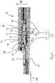
- FIG Fig. 2 Another preferred embodiment of a striking mechanism 10 is shown in FIG Fig. 2 shown.
- the striking mechanism 10 has a striker 30 which can be displaced in an axial direction AR in a striker guide 20.
- the anvil guide 20 is implemented by a first bearing 21 and a second bearing 23 (embodied here as an example as roller bearings), which are each supported against the tool holder 50 both in the radial direction RR and in the axial direction AR.
- the contact piece 35 is designed differently from the striker 30.
- the anvil 30 has a groove 37 which extends in the axial direction AR and in which the contact piece 35 can slide in the axial direction AR.
- the contact piece 35 is movable both with respect to the striker 30 and with respect to the tool holder 50, each seen in the axial direction AR.
- the contact piece 35 is permanently in engagement with the groove 37.
- the striking mechanism 10 of the Fig. 2 has an idle impact damper element 11 which, mediated by an idle impact wedge ring 57 and a first bearing 21 on the one hand and through an idle impact stop ring 56 and the contact piece 35 on the other, acts between the anvil 30 and the tool holder 50. Furthermore, a rebound shock absorber element 13 is provided which, mediated by a rebound impact wedge ring 58 and a second bearing 21 on the one hand and through Bounce stop ring 55 and the contact piece 35 on the other hand, between the striker 30 and the guide housing 50 acts.
- the idle impact wedge ring 57 is arranged between the first bearing 21 of the anvil guide 20 and the idle impact damper element 10.
- the impact impact wedge ring 58 is arranged between the second bearing 23 of the striker guide 20 and the impact impact damper element 13.
- the idle impact wedge ring 57 is supported on its side facing away from the idle impact damper element 10 and in the axial direction AR exclusively against the first bearing 21.
- the rebound impact wedge ring 58 is supported on its side facing away from the rebound impact damper element 13 and in the axial direction exclusively against the second bearing 23.
- the contact piece 35 different from the striker 30 is elastically clamped in the axial direction AR between the idle impact absorber element 11 and the rebound impact absorber element 13. To this extent, when the striking mechanism 10 is in operation, there is no “classic” stop of the contact piece 35 on the idle impact stop ring 56 or the rebound impact stop ring 55.
- an additional idle impact damper element 31 is provided, which acts between the tool holder 50 and the guide housing 80.
- the additional idle impact damper element 31 is supported in the axial direction AR by a guide bearing 85.
- the hammer mechanism 10 is equipped with an elastic impact shock absorber element 13 and an additional elastic impact shock absorber element 33.
- the impact shock absorber element 13 is between the anvil 30 and the guide housing 50, mediated by the impact impact stop ring 55, the impact impact wedge ring 58 and the contact piece 35 effective.
- the additional impact shock absorber element 33 acts between the tool holder 50 and the guide housing 80. In this case, force is introduced from the tool holder 50 into the unit of additional idle impact absorber element 31 and additional impact impact absorber element 33 through a ring 51 protruding from the tool holder in the radial direction RR.
Landscapes
- Engineering & Computer Science (AREA)
- Mechanical Engineering (AREA)
- Percussive Tools And Related Accessories (AREA)
Priority Applications (6)
| Application Number | Priority Date | Filing Date | Title |
|---|---|---|---|
| EP19209451.4A EP3822037A1 (fr) | 2019-11-15 | 2019-11-15 | Agencement de mécanisme de percussion |
| US17/771,658 US12115637B2 (en) | 2019-11-15 | 2020-11-06 | Impact mechanism arrangement |
| EP20800187.5A EP4058252A1 (fr) | 2019-11-15 | 2020-11-06 | Ensemble mécanisme de frappe |
| CN202080067947.8A CN114502330B (zh) | 2019-11-15 | 2020-11-06 | 冲击机构布置 |
| PCT/EP2020/081267 WO2021094214A1 (fr) | 2019-11-15 | 2020-11-06 | Ensemble mécanisme de frappe |
| US18/829,942 US20240424651A1 (en) | 2019-11-15 | 2024-09-10 | Impact mechanism arrangement |
Applications Claiming Priority (1)
| Application Number | Priority Date | Filing Date | Title |
|---|---|---|---|
| EP19209451.4A EP3822037A1 (fr) | 2019-11-15 | 2019-11-15 | Agencement de mécanisme de percussion |
Publications (1)
| Publication Number | Publication Date |
|---|---|
| EP3822037A1 true EP3822037A1 (fr) | 2021-05-19 |
Family
ID=68583200
Family Applications (2)
| Application Number | Title | Priority Date | Filing Date |
|---|---|---|---|
| EP19209451.4A Withdrawn EP3822037A1 (fr) | 2019-11-15 | 2019-11-15 | Agencement de mécanisme de percussion |
| EP20800187.5A Withdrawn EP4058252A1 (fr) | 2019-11-15 | 2020-11-06 | Ensemble mécanisme de frappe |
Family Applications After (1)
| Application Number | Title | Priority Date | Filing Date |
|---|---|---|---|
| EP20800187.5A Withdrawn EP4058252A1 (fr) | 2019-11-15 | 2020-11-06 | Ensemble mécanisme de frappe |
Country Status (4)
| Country | Link |
|---|---|
| US (2) | US12115637B2 (fr) |
| EP (2) | EP3822037A1 (fr) |
| CN (1) | CN114502330B (fr) |
| WO (1) | WO2021094214A1 (fr) |
Families Citing this family (5)
| Publication number | Priority date | Publication date | Assignee | Title |
|---|---|---|---|---|
| EP3822036A1 (fr) * | 2019-11-12 | 2021-05-19 | Hilti Aktiengesellschaft | Agencement de mécanisme de frappe |
| EP3822037A1 (fr) * | 2019-11-15 | 2021-05-19 | Hilti Aktiengesellschaft | Agencement de mécanisme de percussion |
| DE102021203415A1 (de) * | 2021-04-07 | 2022-10-13 | Robert Bosch Gesellschaft mit beschränkter Haftung | Handwerkzeugmaschine mit einer Aktivierungseinheit |
| EP4400265A1 (fr) | 2023-01-11 | 2024-07-17 | Hilti Aktiengesellschaft | Mécanisme de percussion pour marteau perforateur ou marteau burineur |
| EP4733005A1 (fr) * | 2024-10-24 | 2026-04-29 | Hilti Aktiengesellschaft | Dispositif de raccordement d'outil pour un outil électrique, outil électrique avec |
Citations (3)
| Publication number | Priority date | Publication date | Assignee | Title |
|---|---|---|---|---|
| GB618546A (en) * | 1946-10-04 | 1949-02-23 | John Wilbur Tierney | Improvements in or relating to fluid pressure operated engines, such as pneumatic picks or concrete breakers |
| EP1238759A1 (fr) * | 2001-03-07 | 2002-09-11 | Black & Decker Inc. | Marteau |
| WO2009036526A1 (fr) * | 2007-09-21 | 2009-03-26 | Sparky Eltos Ad | Mécanisme percuteur pour marteaux perforateurs électriques |
Family Cites Families (53)
| Publication number | Priority date | Publication date | Assignee | Title |
|---|---|---|---|---|
| US1873173A (en) * | 1929-10-05 | 1932-08-23 | E J Longyear Mfg Co | Cushion diamond drill chuck |
| US2685274A (en) | 1951-04-12 | 1954-08-03 | Phyllis E Liddicoat | Pneumatic tool |
| US2875731A (en) * | 1956-03-23 | 1959-03-03 | Buckeye Steel Castings Co | Vibration absorbers for reciprocating tools |
| GB1195505A (en) * | 1967-07-31 | 1970-06-17 | Hilti Ag | Hammer Drill |
| DE2242944B2 (de) * | 1972-08-31 | 1981-04-23 | Robert Bosch Gmbh, 7000 Stuttgart | Bohrhammer |
| DE2403074C3 (de) * | 1974-01-23 | 1978-10-26 | Demag Ag, 4100 Duisburg | Druckluftbetätigtes Schlagwerkzeug |
| DE2540838C2 (de) * | 1975-09-12 | 1985-05-23 | Hilti Ag, Schaan | Elektropneumatischer Hammer |
| EP0052507B1 (fr) * | 1980-11-18 | 1985-02-13 | Black & Decker Inc. | Perceuse à percussion |
| SE8106907L (sv) * | 1981-11-20 | 1983-05-21 | Atlas Copco Ab | Sett att styra ett slagverk och slagverk |
| DE3224176C2 (de) | 1982-06-29 | 1995-02-02 | Bosch Gmbh Robert | Motorisch angetriebene schlagende Handwerkzeugmaschine |
| DE3241528C2 (de) * | 1982-11-10 | 1986-04-10 | Eugen Lutz GmbH u. Co Maschinenfabrik, 7130 Mühlacker | Werkzeugspannfutter für einen Bohrhammer |
| DE3633675A1 (de) * | 1986-10-03 | 1988-04-14 | Hilti Ag | Bohrhammer mit schlagwerk |
| SU1662832A1 (ru) | 1988-09-23 | 1991-07-15 | Московское Научно-Производственное Объединение По Механизированному Строительному Инструменту И Отделочным Машинам | Машина ударного действи |
| DE4100186A1 (de) * | 1991-01-05 | 1992-07-09 | Bosch Gmbh Robert | Handwerkzeugmaschine mit abnehmbaren werkzeughalter |
| DE4400779A1 (de) | 1994-01-13 | 1995-07-20 | Duss Maschf | Elektropneumatischer Schlag- oder Drehschlaghammer |
| US5573075A (en) * | 1995-07-05 | 1996-11-12 | T.C. Service Company | Pneumatic impact tool having improved vibration and noise attenuation |
| DE19933972A1 (de) * | 1999-07-20 | 2001-01-25 | Bosch Gmbh Robert | Bohr- oder Schlaghammer |
| GB2401570B (en) * | 2003-05-12 | 2006-07-05 | Black & Decker Inc | Spindle assembly for hammer drill |
| US7013986B2 (en) * | 2003-05-12 | 2006-03-21 | Nitto Kohki Co., Ltd. | Impact tool |
| DE10362025B4 (de) | 2003-05-20 | 2006-02-09 | Robert Bosch Gmbh | Bohr- oder Schlaghammer |
| JP4525904B2 (ja) * | 2004-06-08 | 2010-08-18 | 日立工機株式会社 | 打撃工具 |
| DE102005035099A1 (de) * | 2005-07-27 | 2007-02-01 | Robert Bosch Gmbh | Schlagwerk und wenigstens schlagend antreibbare Handwerkzeugmaschine mit einem Schlagwerk |
| JP4686372B2 (ja) * | 2006-02-01 | 2011-05-25 | 株式会社マキタ | 衝撃式作業工具 |
| GB2435442A (en) * | 2006-02-24 | 2007-08-29 | Black & Decker Inc | Powered hammer with helically shaped vent channel |
| US20100038104A1 (en) * | 2006-07-10 | 2010-02-18 | Otto Baumann | Hand held machine tool |
| JP4863942B2 (ja) * | 2006-08-24 | 2012-01-25 | 株式会社マキタ | 打撃工具 |
| JP4815362B2 (ja) * | 2007-02-06 | 2011-11-16 | 株式会社マキタ | 衝撃式作業工具 |
| US7878265B2 (en) * | 2007-02-06 | 2011-02-01 | Makita Corporation | Impact power tool |
| DE102007000131A1 (de) * | 2007-03-07 | 2008-09-11 | Hilti Ag | Handwerkzeugmaschine mit pneumatischem Schlagwerk |
| US7806201B2 (en) * | 2007-07-24 | 2010-10-05 | Makita Corporation | Power tool with dynamic vibration damping |
| JP5100272B2 (ja) | 2007-09-13 | 2012-12-19 | 株式会社マキタ | 打撃工具 |
| DE102008010100A1 (de) * | 2008-02-20 | 2009-08-27 | Robert Bosch Gmbh | Handwerkzeugmaschine |
| JP5147488B2 (ja) * | 2008-03-27 | 2013-02-20 | 株式会社マキタ | 作業工具 |
| SE533344C2 (sv) * | 2009-01-16 | 2010-08-31 | Atlas Copco Rock Drills Ab | Dämpningsanordning för slagverk, slagverk och borrmaskin |
| US8087472B2 (en) * | 2009-07-31 | 2012-01-03 | Black & Decker Inc. | Vibration dampening system for a power tool and in particular for a powered hammer |
| DE102009050014B4 (de) | 2009-10-21 | 2013-07-11 | Metabowerke Gmbh | Motorisch angetriebenes Werkzeuggerät mit Bohrhammerbetriebsart |
| JP5518617B2 (ja) * | 2010-08-02 | 2014-06-11 | 株式会社マキタ | 打撃工具 |
| DE102010044011A1 (de) * | 2010-11-16 | 2012-05-16 | Hilti Aktiengesellschaft | Handwerkzeugmaschine |
| CN103328159B (zh) * | 2011-01-10 | 2015-12-16 | 博世电动工具(中国)有限公司 | 冲击工具 |
| JP5726654B2 (ja) * | 2011-07-01 | 2015-06-03 | 株式会社マキタ | 打撃工具 |
| DE102011079367A1 (de) * | 2011-07-05 | 2013-01-10 | Robert Bosch Gmbh | Schlagwerkvorrichtung |
| DE102011081990A1 (de) * | 2011-09-01 | 2013-03-07 | Robert Bosch Gmbh | Handwerkzeugmaschine |
| JP2013151055A (ja) * | 2012-01-26 | 2013-08-08 | Makita Corp | 打撃工具 |
| WO2015000129A1 (fr) | 2013-07-02 | 2015-01-08 | Chen Zhenyu | Dispositif d'impact et machine-outil pour opération d'impact |
| EP2842696B1 (fr) * | 2013-08-30 | 2016-06-01 | HILTI Aktiengesellschaft | Outil électrique |
| EP2871030A1 (fr) * | 2013-11-06 | 2015-05-13 | HILTI Aktiengesellschaft | Machine-outil manuelle |
| JP6105454B2 (ja) * | 2013-11-26 | 2017-03-29 | 株式会社マキタ | 作業工具 |
| EP2886261A1 (fr) * | 2013-12-18 | 2015-06-24 | HILTI Aktiengesellschaft | Machine-outil manuelle |
| EP2918376A1 (fr) * | 2014-03-12 | 2015-09-16 | HILTI Aktiengesellschaft | Machine-outil portative de burinage |
| EP3231560A1 (fr) * | 2016-04-13 | 2017-10-18 | HILTI Aktiengesellschaft | Machine-outil portative |
| EP3335838A1 (fr) * | 2016-12-15 | 2018-06-20 | HILTI Aktiengesellschaft | Machine-outil portative |
| EP3822030A1 (fr) | 2019-11-15 | 2021-05-19 | Hilti Aktiengesellschaft | Marteau perforateur et/ou burin avec agencement de mécanisme de percussion |
| EP3822037A1 (fr) | 2019-11-15 | 2021-05-19 | Hilti Aktiengesellschaft | Agencement de mécanisme de percussion |
-
2019
- 2019-11-15 EP EP19209451.4A patent/EP3822037A1/fr not_active Withdrawn
-
2020
- 2020-11-06 EP EP20800187.5A patent/EP4058252A1/fr not_active Withdrawn
- 2020-11-06 WO PCT/EP2020/081267 patent/WO2021094214A1/fr not_active Ceased
- 2020-11-06 CN CN202080067947.8A patent/CN114502330B/zh active Active
- 2020-11-06 US US17/771,658 patent/US12115637B2/en active Active
-
2024
- 2024-09-10 US US18/829,942 patent/US20240424651A1/en active Pending
Patent Citations (3)
| Publication number | Priority date | Publication date | Assignee | Title |
|---|---|---|---|---|
| GB618546A (en) * | 1946-10-04 | 1949-02-23 | John Wilbur Tierney | Improvements in or relating to fluid pressure operated engines, such as pneumatic picks or concrete breakers |
| EP1238759A1 (fr) * | 2001-03-07 | 2002-09-11 | Black & Decker Inc. | Marteau |
| WO2009036526A1 (fr) * | 2007-09-21 | 2009-03-26 | Sparky Eltos Ad | Mécanisme percuteur pour marteaux perforateurs électriques |
Also Published As
| Publication number | Publication date |
|---|---|
| WO2021094214A1 (fr) | 2021-05-20 |
| EP4058252A1 (fr) | 2022-09-21 |
| US20240424651A1 (en) | 2024-12-26 |
| CN114502330A (zh) | 2022-05-13 |
| US12115637B2 (en) | 2024-10-15 |
| CN114502330B (zh) | 2025-09-05 |
| US20220362916A1 (en) | 2022-11-17 |
Similar Documents
| Publication | Publication Date | Title |
|---|---|---|
| WO2021094214A1 (fr) | Ensemble mécanisme de frappe | |
| EP1882559B1 (fr) | Outil à main doté d'un dispositif de découplage | |
| EP1326736B1 (fr) | Porte-outil pour une machine-outil | |
| WO2021094213A1 (fr) | Ensemble mécanisme de percussion | |
| DE19933972A1 (de) | Bohr- oder Schlaghammer | |
| WO2013004459A1 (fr) | Dispositif à percussion | |
| EP1967329A2 (fr) | Machine-outil manuelle dotée d'un mécanisme de frappe pneumatique | |
| WO2007141080A1 (fr) | Mécanisme de percussion avec un percuteur et un dispositif d'arrêt affecté | |
| DE102008000727A1 (de) | Tragbare Werkzeugmaschine, insbesondere Bohr- oder Schlaghammer, mit einer Schlägerfangeinrichtung und/oder Schlägerdämpfungseinrichtung | |
| EP1910039B1 (fr) | Mécanisme de percussion pour un outil portatif utilisé au moins en percussion | |
| EP4058251B1 (fr) | Agencement de mécanisme de frappe | |
| DE102011079367A1 (de) | Schlagwerkvorrichtung | |
| WO2024149530A1 (fr) | Mécanisme de percussion pour perceuse à percussion ou marteau-burineur | |
| DE102009028506A1 (de) | Handwerkzeugmaschinenvorrichtung | |
| EP4733006A1 (fr) | Mécanisme de percussion pneumatique pour marteau perforateur ou marteau burineur | |
| EP3996878B1 (fr) | Lèvre de scellement au raccordement d'outil | |
| DE102021211161A1 (de) | Handwerkzeugmaschine mit einem Schlagwerk und einem Dämpfungselement | |
| EP4626644A1 (fr) | Dispositif porte-outil pour marteau perforateur ou marteau burineur | |
| EP2512749B1 (fr) | Dispositif de machine-outil | |
| EP3763467A1 (fr) | Couvercle de protection anti-poussière à découplage de vibrations | |
| EP4733619A1 (fr) | Dispositif amortisseur de chocs pour outil à main électrique équipé d'un mécanisme de percussion | |
| EP4378629A1 (fr) | Dispositif de réception d'outil pour un marteau perforateur ou burineur doté d'un amortissement de frappe à vide et de percussion | |
| DE3421825A1 (de) | Vibrationsminderung mittels variablem anpressdruck bei drucklufthaemmern | |
| DE2511045A1 (de) | Von hand fuehrbarer hammer mit einer das werkzeuglager vor staub schuetzenden manschette | |
| DE102009045656A1 (de) | Werkzeugvorrichtung |
Legal Events
| Date | Code | Title | Description |
|---|---|---|---|
| PUAI | Public reference made under article 153(3) epc to a published international application that has entered the european phase |
Free format text: ORIGINAL CODE: 0009012 |
|
| STAA | Information on the status of an ep patent application or granted ep patent |
Free format text: STATUS: THE APPLICATION HAS BEEN PUBLISHED |
|
| AK | Designated contracting states |
Kind code of ref document: A1 Designated state(s): AL AT BE BG CH CY CZ DE DK EE ES FI FR GB GR HR HU IE IS IT LI LT LU LV MC MK MT NL NO PL PT RO RS SE SI SK SM TR |
|
| STAA | Information on the status of an ep patent application or granted ep patent |
Free format text: STATUS: THE APPLICATION IS DEEMED TO BE WITHDRAWN |
|
| 18D | Application deemed to be withdrawn |
Effective date: 20211120 |