EP3822458B1 - Turbine à gaz pour centrale énergétique et procédé de rééquipement d'une turbine à gaz pour centrale énergétique déjà en service - Google Patents
Turbine à gaz pour centrale énergétique et procédé de rééquipement d'une turbine à gaz pour centrale énergétique déjà en service Download PDFInfo
- Publication number
- EP3822458B1 EP3822458B1 EP19209597.4A EP19209597A EP3822458B1 EP 3822458 B1 EP3822458 B1 EP 3822458B1 EP 19209597 A EP19209597 A EP 19209597A EP 3822458 B1 EP3822458 B1 EP 3822458B1
- Authority
- EP
- European Patent Office
- Prior art keywords
- membrane
- gas turbine
- seal
- turbine
- vane
- Prior art date
- Legal status (The legal status is an assumption and is not a legal conclusion. Google has not performed a legal analysis and makes no representation as to the accuracy of the status listed.)
- Active
Links
Images




Classifications
-
- F—MECHANICAL ENGINEERING; LIGHTING; HEATING; WEAPONS; BLASTING
- F01—MACHINES OR ENGINES IN GENERAL; ENGINE PLANTS IN GENERAL; STEAM ENGINES
- F01D—NON-POSITIVE DISPLACEMENT MACHINES OR ENGINES, e.g. STEAM TURBINES
- F01D11/00—Preventing or minimising internal leakage of working-fluid, e.g. between stages
-
- F—MECHANICAL ENGINEERING; LIGHTING; HEATING; WEAPONS; BLASTING
- F01—MACHINES OR ENGINES IN GENERAL; ENGINE PLANTS IN GENERAL; STEAM ENGINES
- F01D—NON-POSITIVE DISPLACEMENT MACHINES OR ENGINES, e.g. STEAM TURBINES
- F01D11/00—Preventing or minimising internal leakage of working-fluid, e.g. between stages
- F01D11/001—Preventing or minimising internal leakage of working-fluid, e.g. between stages for sealing space between stator blade and rotor
-
- F—MECHANICAL ENGINEERING; LIGHTING; HEATING; WEAPONS; BLASTING
- F01—MACHINES OR ENGINES IN GENERAL; ENGINE PLANTS IN GENERAL; STEAM ENGINES
- F01D—NON-POSITIVE DISPLACEMENT MACHINES OR ENGINES, e.g. STEAM TURBINES
- F01D11/00—Preventing or minimising internal leakage of working-fluid, e.g. between stages
- F01D11/005—Sealing means between non relatively rotating elements
-
- F—MECHANICAL ENGINEERING; LIGHTING; HEATING; WEAPONS; BLASTING
- F01—MACHINES OR ENGINES IN GENERAL; ENGINE PLANTS IN GENERAL; STEAM ENGINES
- F01D—NON-POSITIVE DISPLACEMENT MACHINES OR ENGINES, e.g. STEAM TURBINES
- F01D9/00—Stators
- F01D9/02—Nozzles; Nozzle boxes; Stator blades; Guide conduits, e.g. individual nozzles
- F01D9/023—Transition ducts between combustor cans and first stage of the turbine in gas-turbine engines; their cooling or sealings
-
- F—MECHANICAL ENGINEERING; LIGHTING; HEATING; WEAPONS; BLASTING
- F01—MACHINES OR ENGINES IN GENERAL; ENGINE PLANTS IN GENERAL; STEAM ENGINES
- F01D—NON-POSITIVE DISPLACEMENT MACHINES OR ENGINES, e.g. STEAM TURBINES
- F01D9/00—Stators
- F01D9/02—Nozzles; Nozzle boxes; Stator blades; Guide conduits, e.g. individual nozzles
- F01D9/04—Nozzles; Nozzle boxes; Stator blades; Guide conduits, e.g. individual nozzles forming ring or sector
- F01D9/042—Nozzles; Nozzle boxes; Stator blades; Guide conduits, e.g. individual nozzles forming ring or sector fixing blades to stators
-
- F—MECHANICAL ENGINEERING; LIGHTING; HEATING; WEAPONS; BLASTING
- F02—COMBUSTION ENGINES; HOT-GAS OR COMBUSTION-PRODUCT ENGINE PLANTS
- F02C—GAS-TURBINE PLANTS; AIR INTAKES FOR JET-PROPULSION PLANTS; CONTROLLING FUEL SUPPLY IN AIR-BREATHING JET-PROPULSION PLANTS
- F02C7/00—Features, components parts, details or accessories, not provided for in, or of interest apart form groups F02C1/00 - F02C6/00; Air intakes for jet-propulsion plants
- F02C7/28—Arrangement of seals
-
- F—MECHANICAL ENGINEERING; LIGHTING; HEATING; WEAPONS; BLASTING
- F16—ENGINEERING ELEMENTS AND UNITS; GENERAL MEASURES FOR PRODUCING AND MAINTAINING EFFECTIVE FUNCTIONING OF MACHINES OR INSTALLATIONS; THERMAL INSULATION IN GENERAL
- F16J—PISTONS; CYLINDERS; SEALINGS
- F16J15/00—Sealings
- F16J15/02—Sealings between relatively-stationary surfaces
- F16J15/06—Sealings between relatively-stationary surfaces with solid packing compressed between sealing surfaces
- F16J15/08—Sealings between relatively-stationary surfaces with solid packing compressed between sealing surfaces with exclusively metal packing
- F16J15/0887—Sealings between relatively-stationary surfaces with solid packing compressed between sealing surfaces with exclusively metal packing the sealing effect being obtained by elastic deformation of the packing
-
- F—MECHANICAL ENGINEERING; LIGHTING; HEATING; WEAPONS; BLASTING
- F05—INDEXING SCHEMES RELATING TO ENGINES OR PUMPS IN VARIOUS SUBCLASSES OF CLASSES F01-F04
- F05D—INDEXING SCHEME FOR ASPECTS RELATING TO NON-POSITIVE-DISPLACEMENT MACHINES OR ENGINES, GAS-TURBINES OR JET-PROPULSION PLANTS
- F05D2220/00—Application
- F05D2220/30—Application in turbines
- F05D2220/32—Application in turbines in gas turbines
- F05D2220/321—Application in turbines in gas turbines for a special turbine stage
- F05D2220/3212—Application in turbines in gas turbines for a special turbine stage the first stage of a turbine
-
- F—MECHANICAL ENGINEERING; LIGHTING; HEATING; WEAPONS; BLASTING
- F05—INDEXING SCHEMES RELATING TO ENGINES OR PUMPS IN VARIOUS SUBCLASSES OF CLASSES F01-F04
- F05D—INDEXING SCHEME FOR ASPECTS RELATING TO NON-POSITIVE-DISPLACEMENT MACHINES OR ENGINES, GAS-TURBINES OR JET-PROPULSION PLANTS
- F05D2240/00—Components
- F05D2240/10—Stators
- F05D2240/12—Fluid guiding means, e.g. vanes
-
- F—MECHANICAL ENGINEERING; LIGHTING; HEATING; WEAPONS; BLASTING
- F05—INDEXING SCHEMES RELATING TO ENGINES OR PUMPS IN VARIOUS SUBCLASSES OF CLASSES F01-F04
- F05D—INDEXING SCHEME FOR ASPECTS RELATING TO NON-POSITIVE-DISPLACEMENT MACHINES OR ENGINES, GAS-TURBINES OR JET-PROPULSION PLANTS
- F05D2260/00—Function
- F05D2260/20—Heat transfer, e.g. cooling
Definitions
- the present invention relates to the technical field of the gas turbines for power plants and the methods for retrofitting gas turbines for power plants already in service.
- a gas turbine assembly (or only gas turbine) an incoming air flow is compressed and after ignited in a combustor with an added fuel to produce a hot gas flow to be expanded in a turbine for generating a rotating work on a rotor in turn connected to a generator. Due to the very high temperature of the working hot gas, some components of a gas turbine assembly have to be cooled and therefore beside of the main hot gas flow also a cooling flow (usually cooling air) is circulating inside the gas turbine. Moreover, some components of a gas turbine are configured to allow some relative movements depending on the working condition.
- the present invention in detail refers to the technical problem of how to seal a gas turbine interface for separating the cooling air flow from the hot gas flow wherein this sealing has to be guaranteed during all operating or working conditions.
- a gas turbine assembly for power plants comprises a compressor assembly, a combustor assembly and a turbine assembly.
- the compressor assembly is configured for compressing incoming air supplied at a compressor inlet.
- the compressed air leaving the compressor assembly flows into a volume (called "plenum") and from there into the combustor assembly.
- This combustor assembly comprises usually a plurality of burners configured for injecting fuel (at least one type of fuel) into the compressed air flow.
- the mixture of fuel and compressed air enters a combustion chamber where this mixture ignites.
- the resulting hot gas flow leaves the combustion chamber and by passing in the turbine assembly performs a rotating work on the rotor connected to a generator.
- the turbine assembly comprises a plurality of stages, or rows, of rotating blades that are interposed by a plurality of stages, or rows, of stator vanes.
- the rotating blades are supported by the rotor whereas the stator vanes are supported by a casing (called “vane carrier”) that is concentric and surrounding the turbine assembly.
- a second turbine unit Downstream the second combustor a second turbine unit is present (called low pressure turbine).
- This kind of gas turbine is produced by the Applicant and is available on the market as "GT26".
- the gas turbine is not provided with the high-pressure turbine and the combustor assembly is realized in form of a plurality of can-combustors.
- Each can-combustor comprises a first combustor and a second combustor arranged directly one downstream the other inside a common can shaped casing.
- this second kind of a sequential gas turbine is produced by the Applicant and is available on the market as "GT36".
- seals are used for sealing the interface between stationary and moving components and/or for separating the hot gas flow from the cooling air flow.
- the sealing of the circumferential interface between the combustor outlet and the first vane row of the turbine is today a challenge because this sealing has to be guaranteed during all operating conditions.
- the vane usually has to be cooled (the temperature of the hot gas leaving the combustor is very high) and moreover the vane can move in both the axial and radial directions.
- the sealing arrangement of the combustor to turbine interface comprises a honeycomb seal arrangement.
- each first vane comprises an inner platform.
- the word "inner” means near to the turbine axis in contrast with the outer end of the vane connected to the outer supporting casing surrounding the turbine.
- This platform comprises of labyrinth teeth acting against a honeycomb seal fixed to the combustor end (i.e. to the end of a combustor liner segment carrier).
- the above honeycomb sealing arrangement involves some drawbacks. In particular, a full seal loss during operation may occurs or a simply partial seal delamination can lead to high leakages in this interface.
- the sealing arrangement of the combustor to turbine interface comprises a membrane seal arrangement extending radially from the end of the combustor liner segment carrier to the vane platform.
- this membrane seal is called "dog-bone” seal because it comprises a membrane connecting an inner spherical end housed in a seat or groove in the combustor liner segment carrier and an outer spherical end housed in a seat or groove in the vane inner platform.
- This solution allows relative vane movements, particularly in the axial direction.
- a standard dog-bone membrane seal (as it will be clear during the description of figure 4 and 5 ) in some cases the vane platform contacts the membrane. This contact reduces the pressure loading and unloads the inner and outer circumferential sealing lines between the spherical ends and the grooves.
- the seal can vibrate resulting in increased wear and the risk of seal damage.
- EP3269937 discloses a gas turbine unit comprising a combustor having a liner, a turbine, arranged downstream of the liner along a main flow gas direction and including a plurality of first stage vanes, a rotor cover support located inwardly of the vanes, and a sealing arrangement at the combustor to turbine interface.
- the sealing arrangement comprises a dogbone seal.
- a primary object of the present invention is to provide a gas turbine suitable for overcoming the above problems of the prior art.
- the primary object of the present invention is to provide a gas turbine having an improved membrane seal arrangement suitable for accommodating larger vane displacements with no reduction in lifetime.
- the invention is a gas turbine according to claim 1.
- a gas turbine according the present invention may comprise a single-stage turbine or a high-pressure turbine followed by a low-pressure turbine.
- the combustor assembly may comprise a single-stage combustor or two sequential stages of combustion. In this last case, these two stages of combustion may be divided by a turbine stage (the above high-pressure turbine) or may be connected directly in series in a common can-shaped casing (a so called can-combustor gas turbine).
- the membrane seal arrangement of the present invention may be placed in many different locations inside the gas turbine.
- a critical location is the combustor to turbine interface, i.e. the interface comprising the upstream end of the combustor casing or liner segment carrier and the downstream first row of vanes.
- the main hot gas flow which flows from upstream to downstream into the vane airfoils and a cooling air flow (for instance compressed air) flowing in a channel or volume below (radially inwards) the vane platform with a seal.
- the volume on the downstream side of the seal is fed with cooling air and is called “the higher-pressure air volume” whereas the volume on the upstream side the seal is called “the lower-pressure volume”.
- the words “upstream” and “downstream” refer to the hot gas flow direction.
- the words “inwards/inner” and “outwards/outer” refer the radial position relative to the axis of the gas turbine.
- the words “axially”, “radially” and “circumferentially” refer to the axis of the gas turbine.
- the present invention provides an improved membrane seal arrangement (or simply a membrane seal) comprising:
- the membrane of the present invention has through holes positioned close to the outer end and configured for feeding cooling air onto the seal contact surface in the vane platform groove.
- the membrane may be provided with a through holes positioned close to the inner end to cool the seal contact surface in the carrier groove and feed the cooling air as purge air into a lower-pressure volume on the upstream side of the membrane seal.
- the outer end is not spherical and has a larger radial depth towards the downstream side to reduce contact stress and rate of material loss, when the vane platform wears into the outer end to create a continuous circumferential sealing contact line, which minimizes cooling air leakage.
- the outer edges are chamfered to provide at least the same assembly lead-in capability as a spherical end.
- the outer end has a smaller radial depth towards the upstream side to form a sacrificial wear surface.
- a vane row consists of separate vanes. Between individual vane platforms there is always an axial mismatch caused by production and assembly tolerances. The thermal movements of individual vanes differ in operation increasing the mismatch between individual vane platforms.
- the sacrificial surface is shaped to allow the mismatched vane platforms to quickly and easily wear into the outer end of the membrane seal and form a continuous circumferential sealing line on the lower-pressure side to minimize cooling air leakage.
- the upstream side of the inner and outer ends of the membrane seal have a wear coating applied to minimize wear and increase the lifetime of the seal.
- the upstream side of vane groove also has a wear coating applied to minimize wear and increase the lifetime of the vane.
- the upstream side of carrier groove also has a wear coating applied to minimize wear and increase the lifetime of the carrier.
- the membrane seal arrangement of the present invention also comprises an upper part and a lower part with overlapping ends to minimize leakage. These overlapping ends require a sectional shape different to that of basic seal sectional shape previously described. In particular, the sectional shape of these ends are configured so that when overlapping the same sectional shape as the rest of the membrane seals results (see the example in figures 11-13 ).
- At least one membrane seal arrangement of the present invention is arranged at the combustor to turbine interface.
- the present invention is a method for retrofitting gas turbines for power plants already in service according to claim 12.
- the former standard "dog-bone” membrane seal is replaced with a new membrane seal according to the present invention, i.e. an "offset" membrane seal.
- FIG. 1 is a schematic view of a first non-limiting example of a gas turbine assembly (or only gas turbine) for power plant 1 that can be provided with the new membrane seal according to the present invention.
- this gas turbine comprises is a so called "sequential-combustion gas turbine" provided with a high-pressure and a low-pressure turbine.
- the gas turbine 1 of figure 1 comprises a compressor 3, a first combustor 31, a high-pressure turbine 5, a second combustor 32 and a low-pressure turbine 7.
- the compressor 3 and the two turbines 5, 7 are part of or are connected to a common rotor 8 rotating about an axis 9 and surrounded by a concentric casing 10.
- the compressor 3 is supplied with air and has rotating blades 18 and stator vanes 19 configured to compress the air entering the compressor 3. Exiting the compressor, the compressed air flows into a plenum 11 and from there into numerous first burners 12 of the first combustor 31 arranged in a circular pattern around the axis 9.
- Each first burner 12 is configured for injecting at least one type of fuel (connected to at least one first fuel supply 13) into the compressed airflow.
- this first burner 12 may be defined as a "premix" burner because is configured for mixing the compressed air and the injected fuel before the ignition.
- the fuel/compressed air mixture flows into a first combustion chamber 4 annularly shaped, where this mixture ignites.
- this mixture is initially ignited by an ignitor, for instance by a spark igniter; once ignited the ignition is self-sustaining and the ignitor is turned off.
- the resulting hot gas leaves the first combustor chamber 4 and is partially expanded in the high-pressure turbine 5 performing work on the rotor 8.
- Downstream of the high-pressure turbine 5 the partially-expanded hot gas flows into a row of second burners 33 where at least one type of fuel is injected by fuel lances 14 (each burner has one lance).
- the partially-expanded gas has a high temperature and contains sufficient oxygen for further combustion that occurs by self-ignition in the second combustion chamber 6 arranged downstream of the row second burners 33.
- These second burners 33 are also called "reheat" burners.
- the reheated hot gas leaves the second combustion chamber 6 and flows in the low-pressure turbine 7 where it is expanded performing work on the rotor 8.
- the low-pressure turbine 7 comprises numerous stages: rows of rotor blades 15 arranged in series in the main flow direction. Such rows of blades 15 are interposed by rows of stator vanes 16.
- the rotor blades 15 are connected to the rotor 8 whereas the stator vanes 16 are connected to a vane carrier 17 that is a concentric casing surrounding the low-pressure turbine 7.
- this gas turbine 1 has numerous seals, in particular many membrane seals arranged, for instance, at the interface of the second combustor to first turbine vane.
- a gas turbine as disclosed in figure 1 may be provided with the new membrane seal of the present invention.
- FIG. 2 is a schematic view of a second not-limiting example of a gas turbine that can be provided with the new membrane seal according to the present invention.
- This gas turbine 20 is also a "sequential-combustion gas turbine” that can be provided with the innovative features according to the present invention.
- figure 2 shows a partial view of a gas turbine 20 with a compressor 29, a turbine 21 and a sequential combustor 22.
- the sequential combustor 22 of figure 2 has numerous so-called can combustors, i.e. numerous bolt-on casings wherein there are numerous of first burners 24, for instance four first burners 24, a first combustion chamber 25, numerous second burners 26, and a second combustion chamber 27.
- an mixer may be provided for adding air into the hot gas leaving the first combustion chamber 25 and creating turbulence in the air/hot gas mixture.
- the sequential combustor arrangement is at least in part housed in an outer casing 28 supporting the individual can combustors 22 arranged in a circular pattern around the turbine axis 23.
- At least one type of fuel is introduced via a first fuel injector (not shown) into the first burners 24 wherein the fuel is mixed with the compressed air supplied by the compressor 29.
- each of the first burners 24 of this embodiment is a "premix" burner configured for generating a premixed flame.
- this gas turbine 20 comprises numerous seals, including membrane seals, which could be arranged for instance at the can combustors to first turbine vane interface.
- a gas turbine as disclosed in figure 2 may be provided with the new membrane seal of the present invention.
- FIG. 3 is a schematic view of a combustor to first vane turbine interface of a gas turbine unit according the prior art.
- This gas turbine 34 comprises at least one combustor schematically represented with reference 35 producing a hot gas flow 36.
- figure 3 shows a combustor 36 to turbine 37 interface. This interface is defined by:
- the prior art practice solution is shown as assembled in figures 4 and as in operation in figure 5 .
- the sealing arrangement comprises a standard "dog-bone” membrane seal 46.
- This "dog-bone” membrane seal 46 has an upper and lower part which overlap near the gas turbine casing split-line and, as shown, has an inner spherical end 47, an outer spherical end 48 and a straight central membrane 49 (provided with a purge air hole 50) connecting the two spherical ends.
- the inner spherical end 47 is housed in a circumferential recess 51 in a carrier 52.
- This carrier 52 may be part of a combustor liner or of a rotor cover.
- the seal outer spherical end 48 is housed in a circumferential recess 53 in the vane inner platform 41. As previously discussed, the two spherical ends require a continuous circumferential contact line with the vane platforms and carrier at positions 57 and 58 to minimize cooling-air leakage into the main flow hot gas.
- the membrane 49 has holes 50 (radially positioned near the center of the membrane) to feed cooling air 56 to purge hot gas out of the cavity 59 between the vane platform and liner segments. This "dog-bone" membrane seal 46 separates the hot gas flow 36 from the cooling air 56.
- volume 54 upstream of the seal 46 is the lower-pressure side whereas the downstream volume 55 (fed with cooling air) is the higher-pressure side.
- Figure 4 shows the assembled position.
- the vane platform 39 has a large radially inwards and axially downstream movement relative to the seal end 48;
- figure 5 shows that upstream face 53 of the groove in vane platform 39 contacts the membrane in the steady-state operating position.
- the pressure drop over the "dog-bone” seal 49 creates a high force at the contact point 59 shown in figure 5 . This contact 59 limits the capability of the "dog-bone” to accommodate operational movements of the vane 39 relative to the carrier 52.
- the seal pressure loading is transferred to the contact point 59, which reduces the lifetime of the "dog-bone” seal because inner and outer sealing contact lines 58 57 unload allowing the "dog-bone” membrane to vibrate. This vibration increases the wear and creates the risk of seal breakup in operation.
- a standard symmetrical "dog-bone” membrane seal as shown in figure 5 , the capacity to accommodate larger displacements of the vane 39 relative to the carrier 52 can only be achieved by increasing the radial height of the membrane. However, increasing the radial height of the membrane seal is usually not possible due to the design requirements of a gas turbine.
- the present invention offers a solution for overcoming the above drawbacks and allowing a larger vane relative movements in the downstream direction (i.e. downstream with respect to the main hot gas flow direction).
- the new solution proposed is to provide a membrane seal with ends in grooves vane platforms and in a carrier and the ends are connected by a membrane that is offset towards the higher-pressure side (i.e. downstream side of the seal).
- Figure 6 shows an embodiment according this invention wherein the elements also shown in figure 4 and 5 have been labelled with the same reference numbers. Since the invention refers also to servicing method of replacing the "dog-seal" seal, all adjacent parts are the are the same as shown in figures 4 and 5 .
- this example of the improved membrane seal 60 comprises an inner end 61 configured to create a continuous circumferential sealing line of contact 57 on the upstream surface of the carrier groove 51.
- the new membrane seal 60 comprises an outer end 62 configured to create a continuous circumferential sealing line of contact 63 on the upstream surface of the vane platform grooves 53.
- the membrane 64 is offset towards the higher-pressure side 55, i.e. is connected to the outer end 62 not in the central position but close to the downstream higher-pressure side of the outer end 62.
- the outer portion of the seal therefore has a "P"-shaped profile.
- the membrane 64 is also not centrally connected to inner end 61; the membrane is offset towards the lower-pressure side of the seal at the inner end 61 so that the seal can accommodate larger vane relative movements without contact of the membrane to the carrier.
- the complete sectional profile of seal 60 may be defined as substantially "S" shaped.
- the seal in figure 6 also shows two rows of through holes 66 65 in the membrane 64 position close to the seal ends 61 62.
- the cooling air passing through the inner row of holes 65 cools the seal inner end and the groove contact surface, as well as performing its main function of purging hot gas out the cavity between the vane platforms and the liner segments; the cooling air passing through the outer row of holes 66 cools the seal outer end and the groove contact surfaces, before exiting into the cavity purge hot gas.
- the outer row of holes 66 are inclined to directing the cooling air onto the groove surface 53 close to the line of contact 63.
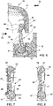
- Figure 7 discloses another embodiment of a seal invention according to the invention, i.e. a seal having membrane offset towards the higher-pressure side of the seal at the outer end.
- the inner end 61 is circular and the membrane 64 is centrally connected to the inner end 61.
- the membrane 64 is has a single row of through holes 67 feeding cooling air into the cavity to purge hot gas; the seal outer end 62 at the sealing line of contact 63 has a reduced radial depth and is a sacrificial wear surface.
- Figure 8 shows another embodiment of the seal invention.
- the seal is very similar to the seal in figure 7 .
- the seal of figure 8 comprises two rows of holes as shown in figure 6 and the outer end 62 has a circumferential pattern of slots 68 on the higher-pressure side to reduce hoop stress resulting from the asymmetry of the end profile.
- Figure 9 and 10 show two different operating conditions of the seal in figure 6 .
- figure 9 shows the position of the components after assembly (as figure 6 )
- figure 10 shows the position of the components in steady-state operating condition (the vane platform displaces radially inwards and axially downstream relative to the carrier).
- the seal of the present invention can accommodate larger vane movements relative to the carrier because the membrane is offset. In the operating position of figure 10 there is no contact of the vane platform nor the carrier to the membrane connecting the two ends of the seal.
- the seal of the present invention has an upper and lower part, which overlap close to the gas turbine casing split-line so that the entire circumference of the combustor to vane interface is sealed.
- the seal sectional profile of the seal upper and lower part at the overlap is such that when the seal is assembled the sectional profile at the overlapped position a seal is the same as at seal sectional section at all other circumferential positions.
- Figures 11 and 12 show ends of the upper and lower part that when overlapping as shown in figure 13 have the same sectional profile as the rest of the seal.
Landscapes
- Engineering & Computer Science (AREA)
- General Engineering & Computer Science (AREA)
- Mechanical Engineering (AREA)
- Chemical & Material Sciences (AREA)
- Combustion & Propulsion (AREA)
- Turbine Rotor Nozzle Sealing (AREA)
Claims (15)
- Turbine à gaz pour centrale électrique ; la turbine à gaz (1, 20) comprenant :- au moins une turbine (5, 7, 21, 34) munie d'au moins une rangée d'aubes de stator (16, 39) conçues pour guider un flux de gaz chaud (36) ; chaque aube (16, 39) étant reliée vers l'extérieur à un carter extérieur (17, 40) et comprenant une plate-forme intérieure (41) ;- un support de segment de chemise (52) positionné radialement vers l'intérieur par rapport à la plate-forme intérieure d'aubes (41) ;- un joint à membrane (46) s'étendant du support (52) à la plate-forme intérieure d'aubes (41) pour isoler le gaz chaud d'un air de refroidissement à pression plus élevée dans un volume (55) situé sous la plate-forme intérieure d'aubes (41) et en aval du joint à membrane (46) qui est alimenté par l'air de refroidissement (56) ;dans laquelle le joint à membrane (46) comprend :- une extrémité intérieure (61) logée dans une rainure (51) du support (52) ;- une extrémité extérieure (62) logée dans une rainure (53) dans la plate-forme intérieure d'aubes (41) ;- une membrane (64) reliant l'extrémité intérieure (61) à l'extrémité extérieure (62) ;caractérisée en ce que
la membrane (64) est décalée par rapport à l'extrémité extérieure (62) en direction du volume à pression plus élevée (55) de sorte que le joint à membrane (46) présente une partie extérieure avec un profil en forme de « P ». - Turbine à gaz selon la revendication 1, dans laquelle la membrane (46) est pourvue d'une rangée de trous traversants (66) positionnés à proximité de l'extrémité extérieure de joint (62) pour alimenter en air de refroidissement le côté amont de la rainure (53) dans les plates-formes intérieures d'aubes (41).
- Turbine à gaz selon la revendication 1 ou 2, dans laquelle la membrane (46) est munie d'une rangée de trous traversants (65) positionnés à proximité de l'extrémité intérieure (61) ou positionnés de manière centrale (67) sur la membrane radiale (64) pour alimenter en air de refroidissement, en tant qu'air de purge, un volume à pression inférieure (54) en amont du joint à membrane (46).
- Turbine à gaz selon l'une quelconque des revendications précédentes, dans laquelle l'extrémité extérieure (62) présente un motif circonférentiel de fentes (68).
- Turbine à gaz selon l'une quelconque des revendications précédentes, dans laquelle l'extrémité extérieure (62) comprend une partie amont (63) ayant une profondeur radiale réduite pour agir comme une surface d'usure sacrificielle de sorte qu'une ligne d'étanchéité circonférentielle continue se forme entre l'extrémité extérieure de joint (62) et les rainures d'aube individuelles décalées axialement (53).
- Turbine à gaz selon l'une quelconque des revendications précédentes, dans laquelle un revêtement d'usure est appliqué sur le côté amont de l'extrémité extérieure (62) et sur les surfaces adjacentes du côté amont de la membrane (64).
- Turbine à gaz selon l'une quelconque des revendications précédentes, dans laquelle un revêtement d'usure est appliqué sur le côté amont de l'extrémité intérieure (61) et sur les surfaces adjacentes du côté amont de la membrane (64).
- Turbine à gaz selon l'une quelconque des revendications précédentes, dans laquelle le profil en coupe du joint à membrane (46) est sensiblement en forme de « S ».
- Turbine à gaz selon l'une quelconque des revendications précédentes, dans laquelle l'extrémité intérieure (61) et/ou l'extrémité extérieure (62) est/sont de forme sensiblement circulaire.
- Turbine à gaz selon l'une quelconque des revendications précédentes, comprenant une partie supérieure de joint à membrane (46) et une partie inférieure de joint à membrane (46) dans la direction circonférentielle, les joints à membrane (46) ayant des profils en coupe aux extrémités à produire lorsqu'ils chevauchent le même profil en coupe qu'à toutes les autres positions circonférentielles sur les joints à membrane (46).
- Turbine à gaz selon l'une quelconque des revendications précédentes, comprenant au moins une chambre de combustion, le joint à membrane (46) étant disposé au niveau de l'interface entre la chambre de combustion et la turbine.
- Procédé de rééquipement de turbines à gaz pour une centrale électrique déjà en service ; le procédé comprenant les étapes suivantes :a) la fourniture d'un ensemble turbine à gaz (5, 7, 21, 34) selon le préambule de la revendication 1 comprenant une pluralité d'anciens joints à membrane ;b) la fourniture d'une pluralité de joints à membrane (46) selon la partie caractérisante de la revendication 1 ;c) le remplacement des anciens joints à membrane par les joints à membrane selon la partie caractérisante de la revendication 1.
- Procédé selon la revendication 12, dans lequel l'étape a) de fourniture d'un ensemble turbine à gaz est réalisée en fournissant une turbine à gaz séquentielle (1) comprenant une turbine haute pression (5) et une turbine basse pression (7).
- Procédé selon la revendication 12, dans lequel l'étape a) de fourniture d'un ensemble turbine à gaz est réalisée en fournissant une turbine à gaz séquentielle (20) comprenant une pluralité de chambres de combustion tubulaires (22).
- Procédé selon l'une quelconque des revendications précédentes 12 à 14, dans lequel l'étape c) de remplacement des anciens joints à membrane par les joints à membrane (46) selon la revendication 1 est réalisée en remplaçant les anciens joints à membrane disposés au niveau de l'interface entre la chambre de combustion et la turbine.
Priority Applications (2)
| Application Number | Priority Date | Filing Date | Title |
|---|---|---|---|
| EP19209597.4A EP3822458B1 (fr) | 2019-11-15 | 2019-11-15 | Turbine à gaz pour centrale énergétique et procédé de rééquipement d'une turbine à gaz pour centrale énergétique déjà en service |
| CN202011267752.6A CN112814744B (zh) | 2019-11-15 | 2020-11-13 | 用于发电厂的燃气涡轮组件和维护燃气涡轮组件的方法 |
Applications Claiming Priority (1)
| Application Number | Priority Date | Filing Date | Title |
|---|---|---|---|
| EP19209597.4A EP3822458B1 (fr) | 2019-11-15 | 2019-11-15 | Turbine à gaz pour centrale énergétique et procédé de rééquipement d'une turbine à gaz pour centrale énergétique déjà en service |
Publications (2)
| Publication Number | Publication Date |
|---|---|
| EP3822458A1 EP3822458A1 (fr) | 2021-05-19 |
| EP3822458B1 true EP3822458B1 (fr) | 2023-01-04 |
Family
ID=68609891
Family Applications (1)
| Application Number | Title | Priority Date | Filing Date |
|---|---|---|---|
| EP19209597.4A Active EP3822458B1 (fr) | 2019-11-15 | 2019-11-15 | Turbine à gaz pour centrale énergétique et procédé de rééquipement d'une turbine à gaz pour centrale énergétique déjà en service |
Country Status (2)
| Country | Link |
|---|---|
| EP (1) | EP3822458B1 (fr) |
| CN (1) | CN112814744B (fr) |
Families Citing this family (2)
| Publication number | Priority date | Publication date | Assignee | Title |
|---|---|---|---|---|
| CN113756883A (zh) * | 2021-09-26 | 2021-12-07 | 中国联合重型燃气轮机技术有限公司 | 一种燃气轮机叶顶间隙主动控制装置及方法 |
| EP4183983B1 (fr) * | 2021-11-23 | 2025-08-27 | Ansaldo Energia Switzerland AG | Ensemble de turbine à gaz pour une centrale électrique ayant un dispositif d'étanchéité à membrane à faible usure pour sceller la chambre de combustion sur l'interface de turbine et procédé d'entretien d'un ensemble de turbine à gaz |
Family Cites Families (7)
| Publication number | Priority date | Publication date | Assignee | Title |
|---|---|---|---|---|
| US4379560A (en) * | 1981-08-13 | 1983-04-12 | Fern Engineering | Turbine seal |
| US4566851A (en) * | 1984-05-11 | 1986-01-28 | United Technologies Corporation | First stage turbine vane support structure |
| US5149250A (en) * | 1991-02-28 | 1992-09-22 | General Electric Company | Gas turbine vane assembly seal and support system |
| GB0722511D0 (en) * | 2007-11-19 | 2007-12-27 | Rolls Royce Plc | Turbine arrangement |
| US9010122B2 (en) * | 2012-07-27 | 2015-04-21 | United Technologies Corporation | Turbine engine combustor and stator vane assembly |
| US9500094B1 (en) * | 2013-04-23 | 2016-11-22 | S & J Deisgn, Llc | Turbine with radial acting seal |
| EP3269937B1 (fr) * | 2016-07-15 | 2020-06-10 | Ansaldo Energia Switzerland AG | Ensemble d'étanchéité sur la chambre de combustion à interface de turbine dans une turbine à gaz |
-
2019
- 2019-11-15 EP EP19209597.4A patent/EP3822458B1/fr active Active
-
2020
- 2020-11-13 CN CN202011267752.6A patent/CN112814744B/zh active Active
Also Published As
| Publication number | Publication date |
|---|---|
| EP3822458A1 (fr) | 2021-05-19 |
| CN112814744A (zh) | 2021-05-18 |
| CN112814744B (zh) | 2025-06-27 |
Similar Documents
| Publication | Publication Date | Title |
|---|---|---|
| US7207771B2 (en) | Turbine shroud segment seal | |
| US20170268776A1 (en) | Gas turbine flow sleeve mounting | |
| EP3933268B1 (fr) | Ensemble pour une turbomachine comprenant une chambre de combustion, un carter externe et un plénum haute presssion | |
| EP3822458B1 (fr) | Turbine à gaz pour centrale énergétique et procédé de rééquipement d'une turbine à gaz pour centrale énergétique déjà en service | |
| EP4183983B1 (fr) | Ensemble de turbine à gaz pour une centrale électrique ayant un dispositif d'étanchéité à membrane à faible usure pour sceller la chambre de combustion sur l'interface de turbine et procédé d'entretien d'un ensemble de turbine à gaz | |
| US6857847B2 (en) | Simplified support device for nozzles of a gas turbine stage | |
| US10544680B2 (en) | Last turbine rotor disk for a gas turbine, rotor for a gas turbine comprising such last turbine rotor disk and gas turbine comprising such rotor | |
| US11802493B2 (en) | Outlet guide vane assembly in gas turbine engine | |
| EP3945246B1 (fr) | Turbine à gaz pour centrales électriques doté d'un dispositif d'étanchéité en nid d'abeilles | |
| EP4174286B1 (fr) | Ensemble turbine à gaz pour centrale électrique avec refroidissement amélioré du rotor et des aubes de turbine et procédé de fonctionnement de cet ensemble turbine à gaz | |
| US11111803B2 (en) | Sealing structure between turbine rotor disk and interstage disk | |
| EP2180143A1 (fr) | Agencement de distributeur de turbine à gaz et turbine à gaz | |
| EP3845810B1 (fr) | Dispositif de support pour des tuiles d'isolation thermique d'une chambre de combustion d'un ensemble turbine à gaz pour centrales électriques et ensemble turbine à gaz | |
| JP4652990B2 (ja) | ガスタービン燃焼器 | |
| KR102566946B1 (ko) | 씰링 어셈블리 및 이를 포함하는 터보머신 | |
| EP4053381B1 (fr) | Dispositif de segment annulaire pour aubes de turbine d'une centrale électrique et ensemble turbine à gaz correspondant pour centrale électrique | |
| EP1799967B1 (fr) | Structure servant a separer les zones interieures d'une turbine haute pression et basse pression | |
| KR102358993B1 (ko) | 터빈 베인 지지체 및 이를 포함하는 터빈 베인 어셈블리 | |
| EP4198265A1 (fr) | Aube pour un ensemble turbine à gaz pour centrale électrique et ensemble turbine à gaz pour centrale électrique comprenant une telle aube | |
| KR101842745B1 (ko) | 가스터빈의 트랜지션피스와 터빈의 결합장치 |
Legal Events
| Date | Code | Title | Description |
|---|---|---|---|
| PUAI | Public reference made under article 153(3) epc to a published international application that has entered the european phase |
Free format text: ORIGINAL CODE: 0009012 |
|
| STAA | Information on the status of an ep patent application or granted ep patent |
Free format text: STATUS: THE APPLICATION HAS BEEN PUBLISHED |
|
| AK | Designated contracting states |
Kind code of ref document: A1 Designated state(s): AL AT BE BG CH CY CZ DE DK EE ES FI FR GB GR HR HU IE IS IT LI LT LU LV MC MK MT NL NO PL PT RO RS SE SI SK SM TR |
|
| STAA | Information on the status of an ep patent application or granted ep patent |
Free format text: STATUS: REQUEST FOR EXAMINATION WAS MADE |
|
| 17P | Request for examination filed |
Effective date: 20211104 |
|
| RBV | Designated contracting states (corrected) |
Designated state(s): AL AT BE BG CH CY CZ DE DK EE ES FI FR GB GR HR HU IE IS IT LI LT LU LV MC MK MT NL NO PL PT RO RS SE SI SK SM TR |
|
| GRAP | Despatch of communication of intention to grant a patent |
Free format text: ORIGINAL CODE: EPIDOSNIGR1 |
|
| STAA | Information on the status of an ep patent application or granted ep patent |
Free format text: STATUS: GRANT OF PATENT IS INTENDED |
|
| INTG | Intention to grant announced |
Effective date: 20220711 |
|
| GRAS | Grant fee paid |
Free format text: ORIGINAL CODE: EPIDOSNIGR3 |
|
| GRAA | (expected) grant |
Free format text: ORIGINAL CODE: 0009210 |
|
| STAA | Information on the status of an ep patent application or granted ep patent |
Free format text: STATUS: THE PATENT HAS BEEN GRANTED |
|
| AK | Designated contracting states |
Kind code of ref document: B1 Designated state(s): AL AT BE BG CH CY CZ DE DK EE ES FI FR GB GR HR HU IE IS IT LI LT LU LV MC MK MT NL NO PL PT RO RS SE SI SK SM TR |
|
| REG | Reference to a national code |
Ref country code: GB Ref legal event code: FG4D |
|
| REG | Reference to a national code |
Ref country code: DE Ref legal event code: R096 Ref document number: 602019023907 Country of ref document: DE |
|
| REG | Reference to a national code |
Ref country code: CH Ref legal event code: EP |
|
| REG | Reference to a national code |
Ref country code: AT Ref legal event code: REF Ref document number: 1542055 Country of ref document: AT Kind code of ref document: T Effective date: 20230115 |
|
| REG | Reference to a national code |
Ref country code: IE Ref legal event code: FG4D |
|
| REG | Reference to a national code |
Ref country code: LT Ref legal event code: MG9D |
|
| REG | Reference to a national code |
Ref country code: NL Ref legal event code: MP Effective date: 20230104 |
|
| REG | Reference to a national code |
Ref country code: AT Ref legal event code: MK05 Ref document number: 1542055 Country of ref document: AT Kind code of ref document: T Effective date: 20230104 |
|
| PG25 | Lapsed in a contracting state [announced via postgrant information from national office to epo] |
Ref country code: NL Free format text: LAPSE BECAUSE OF FAILURE TO SUBMIT A TRANSLATION OF THE DESCRIPTION OR TO PAY THE FEE WITHIN THE PRESCRIBED TIME-LIMIT Effective date: 20230104 |
|
| PG25 | Lapsed in a contracting state [announced via postgrant information from national office to epo] |
Ref country code: RS Free format text: LAPSE BECAUSE OF FAILURE TO SUBMIT A TRANSLATION OF THE DESCRIPTION OR TO PAY THE FEE WITHIN THE PRESCRIBED TIME-LIMIT Effective date: 20230104 Ref country code: PT Free format text: LAPSE BECAUSE OF FAILURE TO SUBMIT A TRANSLATION OF THE DESCRIPTION OR TO PAY THE FEE WITHIN THE PRESCRIBED TIME-LIMIT Effective date: 20230504 Ref country code: NO Free format text: LAPSE BECAUSE OF FAILURE TO SUBMIT A TRANSLATION OF THE DESCRIPTION OR TO PAY THE FEE WITHIN THE PRESCRIBED TIME-LIMIT Effective date: 20230404 Ref country code: LV Free format text: LAPSE BECAUSE OF FAILURE TO SUBMIT A TRANSLATION OF THE DESCRIPTION OR TO PAY THE FEE WITHIN THE PRESCRIBED TIME-LIMIT Effective date: 20230104 Ref country code: LT Free format text: LAPSE BECAUSE OF FAILURE TO SUBMIT A TRANSLATION OF THE DESCRIPTION OR TO PAY THE FEE WITHIN THE PRESCRIBED TIME-LIMIT Effective date: 20230104 Ref country code: HR Free format text: LAPSE BECAUSE OF FAILURE TO SUBMIT A TRANSLATION OF THE DESCRIPTION OR TO PAY THE FEE WITHIN THE PRESCRIBED TIME-LIMIT Effective date: 20230104 Ref country code: ES Free format text: LAPSE BECAUSE OF FAILURE TO SUBMIT A TRANSLATION OF THE DESCRIPTION OR TO PAY THE FEE WITHIN THE PRESCRIBED TIME-LIMIT Effective date: 20230104 Ref country code: AT Free format text: LAPSE BECAUSE OF FAILURE TO SUBMIT A TRANSLATION OF THE DESCRIPTION OR TO PAY THE FEE WITHIN THE PRESCRIBED TIME-LIMIT Effective date: 20230104 |
|
| PG25 | Lapsed in a contracting state [announced via postgrant information from national office to epo] |
Ref country code: SE Free format text: LAPSE BECAUSE OF FAILURE TO SUBMIT A TRANSLATION OF THE DESCRIPTION OR TO PAY THE FEE WITHIN THE PRESCRIBED TIME-LIMIT Effective date: 20230104 Ref country code: PL Free format text: LAPSE BECAUSE OF FAILURE TO SUBMIT A TRANSLATION OF THE DESCRIPTION OR TO PAY THE FEE WITHIN THE PRESCRIBED TIME-LIMIT Effective date: 20230104 Ref country code: IS Free format text: LAPSE BECAUSE OF FAILURE TO SUBMIT A TRANSLATION OF THE DESCRIPTION OR TO PAY THE FEE WITHIN THE PRESCRIBED TIME-LIMIT Effective date: 20230504 Ref country code: GR Free format text: LAPSE BECAUSE OF FAILURE TO SUBMIT A TRANSLATION OF THE DESCRIPTION OR TO PAY THE FEE WITHIN THE PRESCRIBED TIME-LIMIT Effective date: 20230405 Ref country code: FI Free format text: LAPSE BECAUSE OF FAILURE TO SUBMIT A TRANSLATION OF THE DESCRIPTION OR TO PAY THE FEE WITHIN THE PRESCRIBED TIME-LIMIT Effective date: 20230104 |
|
| REG | Reference to a national code |
Ref country code: DE Ref legal event code: R097 Ref document number: 602019023907 Country of ref document: DE |
|
| PG25 | Lapsed in a contracting state [announced via postgrant information from national office to epo] |
Ref country code: SM Free format text: LAPSE BECAUSE OF FAILURE TO SUBMIT A TRANSLATION OF THE DESCRIPTION OR TO PAY THE FEE WITHIN THE PRESCRIBED TIME-LIMIT Effective date: 20230104 Ref country code: RO Free format text: LAPSE BECAUSE OF FAILURE TO SUBMIT A TRANSLATION OF THE DESCRIPTION OR TO PAY THE FEE WITHIN THE PRESCRIBED TIME-LIMIT Effective date: 20230104 Ref country code: EE Free format text: LAPSE BECAUSE OF FAILURE TO SUBMIT A TRANSLATION OF THE DESCRIPTION OR TO PAY THE FEE WITHIN THE PRESCRIBED TIME-LIMIT Effective date: 20230104 Ref country code: DK Free format text: LAPSE BECAUSE OF FAILURE TO SUBMIT A TRANSLATION OF THE DESCRIPTION OR TO PAY THE FEE WITHIN THE PRESCRIBED TIME-LIMIT Effective date: 20230104 Ref country code: CZ Free format text: LAPSE BECAUSE OF FAILURE TO SUBMIT A TRANSLATION OF THE DESCRIPTION OR TO PAY THE FEE WITHIN THE PRESCRIBED TIME-LIMIT Effective date: 20230104 |
|
| PLBE | No opposition filed within time limit |
Free format text: ORIGINAL CODE: 0009261 |
|
| STAA | Information on the status of an ep patent application or granted ep patent |
Free format text: STATUS: NO OPPOSITION FILED WITHIN TIME LIMIT |
|
| PG25 | Lapsed in a contracting state [announced via postgrant information from national office to epo] |
Ref country code: SK Free format text: LAPSE BECAUSE OF FAILURE TO SUBMIT A TRANSLATION OF THE DESCRIPTION OR TO PAY THE FEE WITHIN THE PRESCRIBED TIME-LIMIT Effective date: 20230104 |
|
| 26N | No opposition filed |
Effective date: 20231005 |
|
| PG25 | Lapsed in a contracting state [announced via postgrant information from national office to epo] |
Ref country code: SI Free format text: LAPSE BECAUSE OF FAILURE TO SUBMIT A TRANSLATION OF THE DESCRIPTION OR TO PAY THE FEE WITHIN THE PRESCRIBED TIME-LIMIT Effective date: 20230104 |
|
| P01 | Opt-out of the competence of the unified patent court (upc) registered |
Effective date: 20240430 |
|
| REG | Reference to a national code |
Ref country code: CH Ref legal event code: PL |
|
| PG25 | Lapsed in a contracting state [announced via postgrant information from national office to epo] |
Ref country code: MC Free format text: LAPSE BECAUSE OF FAILURE TO SUBMIT A TRANSLATION OF THE DESCRIPTION OR TO PAY THE FEE WITHIN THE PRESCRIBED TIME-LIMIT Effective date: 20230104 |
|
| PG25 | Lapsed in a contracting state [announced via postgrant information from national office to epo] |
Ref country code: LU Free format text: LAPSE BECAUSE OF NON-PAYMENT OF DUE FEES Effective date: 20231115 |
|
| PG25 | Lapsed in a contracting state [announced via postgrant information from national office to epo] |
Ref country code: CH Free format text: LAPSE BECAUSE OF NON-PAYMENT OF DUE FEES Effective date: 20231130 |
|
| PG25 | Lapsed in a contracting state [announced via postgrant information from national office to epo] |
Ref country code: MC Free format text: LAPSE BECAUSE OF FAILURE TO SUBMIT A TRANSLATION OF THE DESCRIPTION OR TO PAY THE FEE WITHIN THE PRESCRIBED TIME-LIMIT Effective date: 20230104 Ref country code: LU Free format text: LAPSE BECAUSE OF NON-PAYMENT OF DUE FEES Effective date: 20231115 Ref country code: CH Free format text: LAPSE BECAUSE OF NON-PAYMENT OF DUE FEES Effective date: 20231130 |
|
| REG | Reference to a national code |
Ref country code: BE Ref legal event code: MM Effective date: 20231130 |
|
| REG | Reference to a national code |
Ref country code: IE Ref legal event code: MM4A |
|
| PG25 | Lapsed in a contracting state [announced via postgrant information from national office to epo] |
Ref country code: IE Free format text: LAPSE BECAUSE OF NON-PAYMENT OF DUE FEES Effective date: 20231115 |
|
| PG25 | Lapsed in a contracting state [announced via postgrant information from national office to epo] |
Ref country code: BE Free format text: LAPSE BECAUSE OF NON-PAYMENT OF DUE FEES Effective date: 20231130 |
|
| PG25 | Lapsed in a contracting state [announced via postgrant information from national office to epo] |
Ref country code: FR Free format text: LAPSE BECAUSE OF NON-PAYMENT OF DUE FEES Effective date: 20231130 |
|
| PG25 | Lapsed in a contracting state [announced via postgrant information from national office to epo] |
Ref country code: IE Free format text: LAPSE BECAUSE OF NON-PAYMENT OF DUE FEES Effective date: 20231115 Ref country code: FR Free format text: LAPSE BECAUSE OF NON-PAYMENT OF DUE FEES Effective date: 20231130 Ref country code: BE Free format text: LAPSE BECAUSE OF NON-PAYMENT OF DUE FEES Effective date: 20231130 |
|
| PG25 | Lapsed in a contracting state [announced via postgrant information from national office to epo] |
Ref country code: BG Free format text: LAPSE BECAUSE OF FAILURE TO SUBMIT A TRANSLATION OF THE DESCRIPTION OR TO PAY THE FEE WITHIN THE PRESCRIBED TIME-LIMIT Effective date: 20230104 |
|
| PG25 | Lapsed in a contracting state [announced via postgrant information from national office to epo] |
Ref country code: BG Free format text: LAPSE BECAUSE OF FAILURE TO SUBMIT A TRANSLATION OF THE DESCRIPTION OR TO PAY THE FEE WITHIN THE PRESCRIBED TIME-LIMIT Effective date: 20230104 |
|
| PG25 | Lapsed in a contracting state [announced via postgrant information from national office to epo] |
Ref country code: CY Free format text: LAPSE BECAUSE OF FAILURE TO SUBMIT A TRANSLATION OF THE DESCRIPTION OR TO PAY THE FEE WITHIN THE PRESCRIBED TIME-LIMIT; INVALID AB INITIO Effective date: 20191115 |
|
| PG25 | Lapsed in a contracting state [announced via postgrant information from national office to epo] |
Ref country code: HU Free format text: LAPSE BECAUSE OF FAILURE TO SUBMIT A TRANSLATION OF THE DESCRIPTION OR TO PAY THE FEE WITHIN THE PRESCRIBED TIME-LIMIT; INVALID AB INITIO Effective date: 20191115 |
|
| PG25 | Lapsed in a contracting state [announced via postgrant information from national office to epo] |
Ref country code: TR Free format text: LAPSE BECAUSE OF FAILURE TO SUBMIT A TRANSLATION OF THE DESCRIPTION OR TO PAY THE FEE WITHIN THE PRESCRIBED TIME-LIMIT Effective date: 20230104 |
|
| PGFP | Annual fee paid to national office [announced via postgrant information from national office to epo] |
Ref country code: DE Payment date: 20251118 Year of fee payment: 7 |
|
| PGFP | Annual fee paid to national office [announced via postgrant information from national office to epo] |
Ref country code: GB Payment date: 20251120 Year of fee payment: 7 |
|
| PGFP | Annual fee paid to national office [announced via postgrant information from national office to epo] |
Ref country code: IT Payment date: 20251128 Year of fee payment: 7 |