EP3822585B1 - Système de navigation de véhicule et procédé permettant de fournir un guidage de virage à un conducteur d'un véhicule - Google Patents
Système de navigation de véhicule et procédé permettant de fournir un guidage de virage à un conducteur d'un véhicule Download PDFInfo
- Publication number
- EP3822585B1 EP3822585B1 EP19209337.5A EP19209337A EP3822585B1 EP 3822585 B1 EP3822585 B1 EP 3822585B1 EP 19209337 A EP19209337 A EP 19209337A EP 3822585 B1 EP3822585 B1 EP 3822585B1
- Authority
- EP
- European Patent Office
- Prior art keywords
- point
- interest
- route
- vehicle
- turning
- Prior art date
- Legal status (The legal status is an assumption and is not a legal conclusion. Google has not performed a legal analysis and makes no representation as to the accuracy of the status listed.)
- Active
Links
Images

Classifications
-
- G—PHYSICS
- G01—MEASURING; TESTING
- G01C—MEASURING DISTANCES, LEVELS OR BEARINGS; SURVEYING; NAVIGATION; GYROSCOPIC INSTRUMENTS; PHOTOGRAMMETRY OR VIDEOGRAMMETRY
- G01C21/00—Navigation; Navigational instruments not provided for in groups G01C1/00 - G01C19/00
- G01C21/26—Navigation; Navigational instruments not provided for in groups G01C1/00 - G01C19/00 specially adapted for navigation in a road network
- G01C21/34—Route searching; Route guidance
- G01C21/36—Input/output arrangements for on-board computers
- G01C21/3626—Details of the output of route guidance instructions
- G01C21/3644—Landmark guidance, e.g. using POIs or conspicuous other objects
-
- G—PHYSICS
- G01—MEASURING; TESTING
- G01C—MEASURING DISTANCES, LEVELS OR BEARINGS; SURVEYING; NAVIGATION; GYROSCOPIC INSTRUMENTS; PHOTOGRAMMETRY OR VIDEOGRAMMETRY
- G01C21/00—Navigation; Navigational instruments not provided for in groups G01C1/00 - G01C19/00
- G01C21/26—Navigation; Navigational instruments not provided for in groups G01C1/00 - G01C19/00 specially adapted for navigation in a road network
- G01C21/34—Route searching; Route guidance
- G01C21/3453—Special cost functions, i.e. other than distance or default speed limit of road segments
- G01C21/3476—Special cost functions, i.e. other than distance or default speed limit of road segments using point of interest [POI] information, e.g. a route passing visible POIs
Definitions
- the invention relates to a vehicle navigation system and a method for providing turn guidance for a driver of a vehicle. Further, the invention relates to a vehicle comprising such vehicle navigation system.
- the state of the art discloses conventional navigation techniques with informing the road name, the direction to take and the estimated distance to make a turn at a turning point. These solutions are not sufficiently intuitive and are not clearly recognizable by the driver.
- DE 10 2007 014 674 A1 discloses a navigation device and method in which a front camera captures an image to extract a crossing sign that can be displayed in a pronounced manner.
- US 2017/0350719 A1 discloses an electronic navigation system in which external server provides a navigation module, which can calculate routes with user-specific learned landmarks and cause them to be displayed on an interface of a client device.
- EP 3 495 777 A2 discloses a vehicle control system in which a camera captures an image of an object close to an intersection and displays the image on the display unit.
- EP 1 378 724 A1 discloses a route guidance system that can sense the visual activity of a driver and displays a vision guidance reference object on the display in an enlarged manner.
- US 2013/0261969 A1 discloses a guiding technology in which a landmark information is confirmed to be present prior to highlighting the landmark information in the captured image.
- WO2008/147006 A1 discloses an intersection guidance method in which a selected representation POI corresponding to a turning direction is displayed.
- US 2005/0288859 A1 discloses a digital mapping technique in which visually oriented driving directions including waypoints can be given.
- the invention is based on the objective problem to provide a navigation system and a corresponding method that provides an improved and more intuitive guidance to follow the determined route at turning points.
- a vehicle navigation system is provided as appended in claim 1..
- a sensor means may comprise different types of sensors.
- the sensor means may comprise a position sensor, for example GPS sensor, a GLONASS sensor or a Galileo sensor to generate position data indicative of the current geographical position of the vehicle, but the invention is not restricted thereto.
- the sensor means may also comprise a velocity sensor to generate velocity data indicative of the current velocity of the vehicle.
- the display unit may for example be part of an interface unit. The display unit is configured to visualize route information to communicate with the driver.
- a processor unit may be a microprocessor, a central processing unit or the like. The selection of the destination by the user may preferably be performed via a manual selection input, for example by using a user interface.
- a turning point may be a point at which the vehicle has to be manoeuvred to follow the determined route into a different direction.
- the route may be determined based on conventional techniques, e.g. by using the generated position data for geolocation in combination with for example electronic maps for displaying.
- a point of interest may be an object, in particular a geo-object but the invention is not restricted thereto.
- a point of interest suitable for recognition may be a point of interest which the driver should be able to notice when making the turn at the turning point.
- the highlighting of the point of interest may be preferably performed such that the perception of the driver of the determined point of interest on the display unit is improved by the highlighting. Highlighting may mean that the point of interest looks more significant than any other point of interest and thus is perceptive for human and physical recognition. Approaching to the turning point in other words may be expressed as coming to the turning point.
- the invention has the advantage, that the driver of the vehicle is supported when turning at a turning point since the display unit highlights a particularly recognizable point of interest that the driver can see at the turning point in the real environment. The turning for the driver thus becomes more intuitive. Further, the display unit presents the information in a highlighted way such that the physical perception and recognition by the driver of the determined point of interest is improved. This highlighted information provides direct feedback for enabling improved orientation to turn the vehicle and to follow the route correctly avoiding detours. Thereby, also efficiency of transport and transport flow of vehicles is improved. Due to matching of the highlighted point of interest with the actual object to be recognized at the turning point environment makes it easier for the driver to turn since it is more intuitive.
- the processor unit may be configured to determine an estimated time to reach the turning point based on the generated data and is configured to determine that the vehicle is approaching the turning point, when the estimated time is below a threshold time.
- the threshold time may be for example 15 seconds or 10 seconds, but the invention is not restricted thereto.
- the estimated time may be determined based on the distance to the turning point and current velocity, determined by a sensor means, for example a position sensor as for example a GPS sensor or the like, see above, and a velocity sensor. This determination has the advantage that regardless of the current velocity of the vehicle the navigation system provides a sufficient time window for the driver to perceive and recognize the highlighted point of interest on the display unit and in the real environment.
- the processor unit may be configured to determine an estimated distance to the turning point based on the generated data and is configured to determine that the vehicle is approaching the turning point, when the determined distance is below a threshold distance.
- the distance may be determined based on the geographical position data received for example from a geographical sensor. Advantage here is that at crossings with traffic lights or in traffic jams, the distance criterion works reliably when the vehicle is not moving.
- the processor unit may be configured to determine a point of interest among a plurality of points of interest at the turning point according to a stored predetermined priority list based on recognition strength of points of interest for a driver at the turning point. The most suitable point of interest for a particular turning point may thereby be highlighted.
- the processor unit may be configured to determine a point of interest among a plurality of points of interest based on if the point of interest is located on a side of the route to which the route is turning to at the turning point. Thereby, a criterion of a directional position with respect to the initial route of the point of interest is used to determine a most suitable point of interest for recognition.
- the processor unit may be configured to highlight the determined point of interest on the display unit via a colour, via intensity, brightness and/or via an animation. Combinations are also disclosed. These highlighting means improve physical recognition of the determined point of interest by the driver.
- the point of interest may be a sign name, an icon, and/or building recognizable from the driver's point of view at the turning point. Combinations are also disclosed. These are preferable objects that can be usually readily recognized by a driver.
- a vehicle comprising a vehicle navigation system according to one of the above described embodiments is disclosed.
- the advantages of the above method and the above vehicle are similar to the advantages of the corresponding vehicle navigation system as formulated for example above or as in the following.
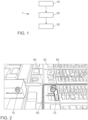
- Fig. 1 shows schematically a vehicle navigation system 1 according to the present invention.
- Fig. 2 shows a display unit 30 not falling under the claimed invention
- Fig. 3 shows a display unit 30 for illustration of embodiments of the present invention.
- the description will be referred to one of the contents of Figs. 1 to 3 , respectively.
- the vehicle navigation system 1 comprises a sensor means 10.
- the sensor means 10 is configured to generate data for use by the vehicle navigation system 1.
- the sensor means 10 may be comprise a positional sensor and/or a velocity sensor, for example a GPS sensor.
- the vehicle navigation system 1 further comprises a display unit 30.
- the vehicle navigation system 1 comprises a processor unit 20.
- the sensor means 10 may be configured to transmit the generated data to the processor unit 20.
- the processor unit 20 may be configured to transmit control signals to the display unit 30 to control the display unit 30 and in particular to control the content to be displayed by the display unit 30.
- the display unit 30 may be part of a user interface and configured to receive a user input for example to select a route destination transmitted to the processor unit 20.
- the processor unit 20 is configured to generate a route 50 to a destination selected by a user based on the generated data by the sensor means 10.
- the processor unit 20 is configured to control the display unit 30 to display the determined route 50, as can be seen in Figs. 2 (not falling under the claimed invention) to 3.
- the route 50 according to the present invention comprises at least one turning point 60 and also at least one point of interest 70, 72 located at the at least one turning point 60, see also the Figs. 2 (not falling under the claimed invention) to 3.
- a turning point 60 may also be referred to as a point of manoeuvre, where the driver has to manoeuvre the vehicle. At such a turning point 60 the driver has to turn the vehicle to follow the route 50 indicated by the display unit 30 or at least to change lanes or the like.
- the turning point 60 is located at a crossing, as can be seen in both examples in Figs. 2 (not falling under the claimed invention) and 3.
- the processor unit 20 is configured to determine based on generated data by the sensor means 10 when the vehicle is approaching a turning point 60.
- the generated data of the sensor means 10 may for example include the current position or the current velocity of the vehicle, but the invention is not restricted thereto.
- the processor unit 20 is configured to determine a point of interest 72 at the turning point 60, wherein the point of interest 72 is suitable for recognition by the driver at the turning point 60.
- the point of interest 72 is suitable for recognition by the driver at the turning point 60.
- wording perception may be used for recognition.
- a building here a restaurant building "Taqueria Chihuahua" is determined as point of interest 72 suitable for recognition.
- the determination of the point of interest 72 is performed when it is determined that the vehicle is approaching the turning point 60 or in other words coming to the turning point 60.
- the point of interest 70, 72 is also often referred to as POI.
- the point of interest 70 may be preferably a sign name, an icon, or a building recognizable from the driver's point of view at the turning point 60, but the invention is not restricted thereto.
- the point of interest 70 may be any object that is suitable for recognition by the driver at the corresponding turning point 60.
- the determined point of interest 72 is a library building "Venice - Abbot Kinney Memorial Branch Library".
- the processor unit 20 is configured to control the display unit 30 to highlight the determined point of interest 72 on the display unit 30 as can be seen in Figs. 2 (not falling under the claimed invention) and 3. In other words, the particular determined point of interest 72 is pointed up, when the vehicle is approaching or coming to the turning point 60.
- the processor unit 20 may be configured to highlight the determined point of interest 72 on the display unit 30 via a colour, via intensity, brightness and/or via an animation. Also here, the invention is not restricted thereto. Any form of highlighting is included, which improves the human physical perception such that driving control is advantageously influenced.
- the present invention has the advantage, that the driver of the vehicle is supported when turning since the display unit 30 highlights a particularly determined recognizable point of interest 72 that the driver can see at the turning point in the real environment.
- the display unit 30 displays the information in a highlighted way thus is perceptive to human and physical recognition.
- the physical perception by the driver of the particularly determined point of interest 72 is improved.
- This highlighted information provides direct feedback for enabling improved orientation to turn the vehicle and to follow the route correctly without additional detours. Thereby, also efficiency of transport and transport flow of vehicles is improved.
- the highlighted point of interest 72 By matching the highlighted point of interest 72 with the actual object to be recognized at the turning point environment the turning of the vehicle by the driver at the turning point is improved and more intuitive.
- the processor unit 20 may be configured to determine an estimated time Te to reach the turning point 60 based on the generated data. Then, the processor unit 20 may be configured to determine that the vehicle is approaching the turning point 60, when the estimated time Te is below a threshold time Tth.
- the generated data by the sensor means 10 may be local position of the vehicle, for example determined by a GPS sensor, and current velocity of the vehicle determined by a velocity sensor, for example by a GPS sensor. Then, the estimated time Te may be determined by the distance to the turning point 60 divided by the velocity.
- the determination has the advantage that regardless of the current velocity of the vehicle the navigation system provides a sufficient time window for the driver to recognize the highlighted point of interest on the display unit and in the real environment.
- the threshold time Tth may be preferably 10 seconds or 15 seconds, but the invention is not restricted thereto.
- the processor unit 20 may be configured to determine an estimated distance D to the turning point 60 based on the generated data and, may be configured to determine that the vehicle is approaching the turning point 60, when the determined distance D is below a threshold distance Dth. Also here, distance may be determined by the processor unit 20 based on position data from the sensor means 10 indicative of a current position and the location of the turning point 60, for example, by calculating the difference between these two location points. Such situation may be useful in cases of traffic lights.
- a threshold distance Dth may be for example 70 m, 50 m, or 30 m, but the invention is not restricted thereto. The latter may be for example suitable in an inner city crossing.
- a hotel building "Marina del Rey Marriott” and a restaurant building “Taqueria Chihuahua” are displayed by the display unit 30 as points of interest.
- a parking lot, a library building "Venice - Abbott Kinney Memorial Branch Library” and a church “Venice Bible Church” are indicated by the display unit 30 as points of interest 70.
- the processor unit 20 is configured to determine a point of interest 72 among a plurality of points of interest 70, 72 at the turning point 60. This may be done, for example, according to a stored predetermined priority list, not falling under the claimed invention, based on recognition strength from a driver's point of view at the turning point 60. For example, it may be stored in a data base that at the turning point 60 in Fig. 3 , the building "Venice - Abbott Kinney Memorial Branch Library" is the most recognizable point of interest 72 for orientation at the particular turning point 60.
- the processor unit 20 may be configured to determine a point of interest 72 among a plurality of points of interest 70, 72 based on if the point of interest 72 is located on a side of the route 50 to which the route is turning to at the turning point 60.
- a point of interest 72 among a plurality of points of interest 70, 72 based on if the point of interest 72 is located on a side of the route 50 to which the route is turning to at the turning point 60.
- two points of interest are generally recognizable, which is the building "Taqueria Chihuahua" and the hotel building "Marina del Rey Marriott".
- the most recognizable building determined by the processor unit 20 may be the restaurant building "Taqueria Chihuahua" as it is located on the right side, as shown in Fig. 2 (not falling under the claimed invention). The latter thus provides better orientation and is therefore determined and highlighted on the display unit 30.
- the processor unit 20 is configured to determine a point of interest 72 among a plurality of points of interest 70, 72 on a side different to the side of the route 50 to which the route 50 is turning to at the turning point 60, only when no point of interest suitable for recognition is determined on the side of the route 50 to which the route 50 is turning to at the turning point 60. I.e., in Fig. 3 , at the turning point 60 the route 50 turns left.
- the processor unit 20 here has determined that the parking lot on the left side is a point of interest 70 with low recognition strength for the driver. Therefore, in this case, the processor unit 20 has determined that the building "Venice-Abbott Kinney Memorial Branch Library" is the point of interest 72 with the highest recognition strength and thus highlights the latter in the display unit 72, see also Fig. 3 .
- a corresponding method for providing turn guidance to a driver of a vehicle comprises providing sensor means 10 configured to generate data for use by a vehicle navigation system 1.
- the method further comprises providing a display unit 30 and a processor unit 20.
- the method further comprises in step S1 generating, by the processor unit 20, a route 50 for the vehicle to a destination selected by a user based on the generated data by the sensor means 10 and control the display unit 30 to display the route 50, wherein the route 50 comprises at least one turning point 60 and at least one point of interest 70 located at the at least one turning point 60.
- the method further comprises in step S2 determine, by the processor unit 20, based on generated data by the sensor means 10 when the vehicle is approaching a turning point 60.
- the method further comprises the step S3 of determine, by the processor unit 20, a point of interest 72 at the turning point 60 suitable for recognition by the driver at the turning point 60, when it is determined that the vehicle is approaching the turning point 60.
- the method further comprises the step S4 of controlling, by the processor unit 20, the display unit 30 to highlight the determined point of interest 72 on the display unit 30. Further method steps can be derived from the above description with respect to the navigation system 1.
Landscapes
- Engineering & Computer Science (AREA)
- Radar, Positioning & Navigation (AREA)
- Remote Sensing (AREA)
- Automation & Control Theory (AREA)
- Physics & Mathematics (AREA)
- General Physics & Mathematics (AREA)
- Navigation (AREA)
Claims (7)
- Système de navigation de véhicule (1), comprenant :- un moyen de détection (10) configuré pour générer des données destinées à être utilisées par le système ;- une unité d'affichage (30) ;- une unité de processeur (20) configurée pour :générer une route (50) pour le véhicule vers une destination sélectionnée par un utilisateur sur la base des données générées par le moyen de détection (10) et commander l'unité d'affichage (30) pour afficher la route (50), dans lequel la route (50) comprend au moins un point de virage (60) et au moins un point d'intérêt (70) situé au niveau de l'au moins un point de virage (60) ;déterminer, sur la base des données générées par le moyen de détection (10), le moment où le véhicule s'approche d'un point de virage (60) ;caractérisé par,lorsqu'il est déterminé que le véhicule s'approche du point de virage (60) :la détermination d'un point d'intérêt (72) susceptible d'être reconnu par le conducteur au niveau du point de virage (60) avec une force de reconnaissance la plus élevée parmi une pluralité de points d'intérêt (70, 72) sur un côté différent du côté de la route (50) vers lequel la route tourne au niveau du point de virage (60), uniquement lorsqu'aucun point d'intérêt susceptible d'être reconnu n'est déterminé sur le côté de la route (50) vers lequel la route (50) tourne au niveau du point de virage (60), en déterminant que tout point d'intérêt sur le côté de la route (50) vers lequel la route (50) tourne au niveau du point de virage (60) est un point d'intérêt (70) avec une faible force de reconnaissance pour le conducteur ; etcommander l'unité d'affichage (30) pour mettre en évidence le point d'intérêt (72) déterminé tout en affichant la pluralité de points d'intérêt (70, 72) sur l'unité d'affichage (30).
- Système (1) selon la revendication 1, dans lequel l'unité de processeur (20) est configurée pour déterminer un temps estimé d'arrivée au point de virage (60) sur la base des données générées et est configurée pour déterminer que le véhicule s'approche du point de virage (60), lorsque le temps estimé (Te) est inférieur à un temps seuil (Tth).
- Système (1) selon l'une des revendications 1 à 2, dans lequel l'unité de processeur (20) est configurée pour déterminer une distance (D) estimée jusqu'au point de virage (60) sur la base des données générées et est configurée pour déterminer que le véhicule s'approche du point de virage (60), lorsque la distance (D) déterminée est inférieure à une distance seuil (Dth).
- Système (1) selon l'une des revendications 1 à 3, dans lequel l'unité de processeur (20) est configurée pour mettre en évidence le point d'intérêt (72) déterminé sur l'unité d'affichage (30) par le biais d'une couleur, d'une intensité, d'une luminosité et/ou d'une animation.
- Système (1) selon l'une des revendications 1 à 4, dans lequel le point d'intérêt (70, 72) est un nom de panneau, une icône, ou un bâtiment reconnaissable du point de vue du conducteur au niveau du point de virage (60).
- Procédé permettant de fournir un guidage de virage à un conducteur d'un véhicule, comprenant :la fourniture d'un moyen de détection (10) configuré pour générer des données destinées à être utilisées par un système de navigation de véhicule (1) ;la fourniture d'une unité d'affichage (30) ;la fourniture d'une unité de processeur (20) ;la génération, par l'unité de processeur (20), d'une route (50) pour le véhicule vers une destination sélectionnée par un utilisateur sur la base des données générées par le moyen de détection (10) et la commande de l'unité d'affichage (30) pour afficher la route (50), dans lequel la route (50) comprend au moins un point de virage (60) et au moins un point d'intérêt (70) situé au niveau de l'au moins un point de virage (60) (S1) ;la détermination, par l'unité de processeur (20), sur la base des données générées par le moyen de détection (10), du moment où le véhicule s'approche d'un point de virage (60) (S2) ;caractérisé en ce que,lorsqu'il est déterminé que le véhicule s'approche du point de virage (60) (S3) : la détermination, par l'unité de processeur (20), d'un point d'intérêt (72) susceptible d'être reconnu par le conducteur au niveau du point de virage (60) avec une force de reconnaissance la plus élevée parmi une pluralité de points d'intérêt (70, 72) sur un côté différent du côté de la route (50) vers lequel la route tourne au niveau du point de virage (60), uniquement lorsqu'aucun point d'intérêt susceptible d'être reconnu n'est déterminé sur le côté de la route (50) vers lequel la route (50) tourne au niveau du point de virage (60), en déterminant que tout point d'intérêt sur le côté de la route (50) vers lequel la route (50) tourne au niveau du point de virage (60) est un point d'intérêt (70) avec une faible force de reconnaissance pour le conducteur ;la commande, par l'unité de processeur (20), de l'unité d'affichage (30) pour mettre en évidence le point d'intérêt (72) déterminé tout en affichant la pluralité de points d'intérêt (70, 72) sur l'unité d'affichage (30) (S4).
- Véhicule comprenant un système de navigation de véhicule (1) selon l'une des revendications 1 à 5.
Priority Applications (1)
| Application Number | Priority Date | Filing Date | Title |
|---|---|---|---|
| EP19209337.5A EP3822585B1 (fr) | 2019-11-15 | 2019-11-15 | Système de navigation de véhicule et procédé permettant de fournir un guidage de virage à un conducteur d'un véhicule |
Applications Claiming Priority (1)
| Application Number | Priority Date | Filing Date | Title |
|---|---|---|---|
| EP19209337.5A EP3822585B1 (fr) | 2019-11-15 | 2019-11-15 | Système de navigation de véhicule et procédé permettant de fournir un guidage de virage à un conducteur d'un véhicule |
Publications (2)
| Publication Number | Publication Date |
|---|---|
| EP3822585A1 EP3822585A1 (fr) | 2021-05-19 |
| EP3822585B1 true EP3822585B1 (fr) | 2025-01-08 |
Family
ID=68583122
Family Applications (1)
| Application Number | Title | Priority Date | Filing Date |
|---|---|---|---|
| EP19209337.5A Active EP3822585B1 (fr) | 2019-11-15 | 2019-11-15 | Système de navigation de véhicule et procédé permettant de fournir un guidage de virage à un conducteur d'un véhicule |
Country Status (1)
| Country | Link |
|---|---|
| EP (1) | EP3822585B1 (fr) |
Family Cites Families (7)
| Publication number | Priority date | Publication date | Assignee | Title |
|---|---|---|---|---|
| DE60304254T2 (de) * | 2002-07-01 | 2006-12-14 | Mazda Motor Corp., Shinchi | Zielführungssystem basiert auf visueller Tätigkeit des Fahrers |
| US7831387B2 (en) * | 2004-03-23 | 2010-11-09 | Google Inc. | Visually-oriented driving directions in digital mapping system |
| JP4935145B2 (ja) * | 2006-03-29 | 2012-05-23 | 株式会社デンソー | カーナビゲーション装置 |
| KR100875375B1 (ko) * | 2007-05-28 | 2008-12-23 | 팅크웨어(주) | 관심지점 정보를 이용한 교차로 안내 방법 및 네비게이션시스템 |
| JP4881493B1 (ja) * | 2010-12-24 | 2012-02-22 | パイオニア株式会社 | ナビゲーション装置、制御方法、プログラム、及び記憶媒体 |
| US10024683B2 (en) * | 2016-06-06 | 2018-07-17 | Uber Technologies, Inc. | User-specific landmarks for navigation systems |
| KR101974871B1 (ko) * | 2017-12-08 | 2019-05-03 | 엘지전자 주식회사 | 차량에 구비된 차량 제어 장치 및 차량의 제어방법 |
-
2019
- 2019-11-15 EP EP19209337.5A patent/EP3822585B1/fr active Active
Also Published As
| Publication number | Publication date |
|---|---|
| EP3822585A1 (fr) | 2021-05-19 |
Similar Documents
| Publication | Publication Date | Title |
|---|---|---|
| JP6907266B2 (ja) | 出力装置、地図情報記憶装置、自動運転制御装置、出力方法、プログラム及び記憶媒体 | |
| AU2018266108B2 (en) | Destination changes in autonomous vehicles | |
| US6529822B1 (en) | Navigation system with zoomed maneuver instruction | |
| US9360331B2 (en) | Transfer of data from image-data-based map services into an assistance system | |
| EP2162849B1 (fr) | Dispositif de détermination de voie, procédé de détermination de voie et appareil de navigation utilisant celui-ci | |
| US6397145B1 (en) | Navigation system with complex maneuver instruction | |
| US20200307616A1 (en) | Methods and systems for driver assistance | |
| US20080243382A1 (en) | Crossroad guide method in a navigation system | |
| US20090177388A1 (en) | Method For Operating A Navigation System | |
| JP4683380B2 (ja) | 車線変更案内装置 | |
| US20130124082A1 (en) | Navigation system and displaying method thereof | |
| JPWO1992021937A1 (ja) | ナビゲーション装置およびナビゲーション方法 | |
| US20230021643A1 (en) | Method for providing a three-dimensional map in a motor vehicle | |
| GB2510698A (en) | Driver assistance system | |
| EP3460778B1 (fr) | Système de guidage de marquage de voies simulé de véhicule automatisé | |
| JPWO2001036912A1 (ja) | ナビゲーション装置及びナビゲーション方法 | |
| KR20220133291A (ko) | 도로 안내 지시 준비 방법 | |
| US10175055B2 (en) | Navigation system | |
| JP4529080B2 (ja) | ナビゲーション装置 | |
| US11034284B2 (en) | Navigational device | |
| EP2557395A1 (fr) | Procédé et système de navigation | |
| CN102564446B (zh) | 为车辆驾驶员确定目的地导航提示的方法和设备 | |
| EP3822585B1 (fr) | Système de navigation de véhicule et procédé permettant de fournir un guidage de virage à un conducteur d'un véhicule | |
| JP2021005219A (ja) | 車両制御装置、ナビゲーション装置、および、車載機器間の経路情報共有方法 | |
| JP4817993B2 (ja) | ナビゲーション装置および誘導経路設定方法 |
Legal Events
| Date | Code | Title | Description |
|---|---|---|---|
| PUAI | Public reference made under article 153(3) epc to a published international application that has entered the european phase |
Free format text: ORIGINAL CODE: 0009012 |
|
| STAA | Information on the status of an ep patent application or granted ep patent |
Free format text: STATUS: THE APPLICATION HAS BEEN PUBLISHED |
|
| AK | Designated contracting states |
Kind code of ref document: A1 Designated state(s): AL AT BE BG CH CY CZ DE DK EE ES FI FR GB GR HR HU IE IS IT LI LT LU LV MC MK MT NL NO PL PT RO RS SE SI SK SM TR |
|
| STAA | Information on the status of an ep patent application or granted ep patent |
Free format text: STATUS: REQUEST FOR EXAMINATION WAS MADE |
|
| 17P | Request for examination filed |
Effective date: 20211119 |
|
| RBV | Designated contracting states (corrected) |
Designated state(s): AL AT BE BG CH CY CZ DE DK EE ES FI FR GB GR HR HU IE IS IT LI LT LU LV MC MK MT NL NO PL PT RO RS SE SI SK SM TR |
|
| STAA | Information on the status of an ep patent application or granted ep patent |
Free format text: STATUS: EXAMINATION IS IN PROGRESS |
|
| 17Q | First examination report despatched |
Effective date: 20230207 |
|
| GRAP | Despatch of communication of intention to grant a patent |
Free format text: ORIGINAL CODE: EPIDOSNIGR1 |
|
| STAA | Information on the status of an ep patent application or granted ep patent |
Free format text: STATUS: GRANT OF PATENT IS INTENDED |
|
| INTG | Intention to grant announced |
Effective date: 20240528 |
|
| GRAS | Grant fee paid |
Free format text: ORIGINAL CODE: EPIDOSNIGR3 |
|
| P01 | Opt-out of the competence of the unified patent court (upc) registered |
Free format text: CASE NUMBER: APP_43421/2024 Effective date: 20240725 |
|
| GRAA | (expected) grant |
Free format text: ORIGINAL CODE: 0009210 |
|
| STAA | Information on the status of an ep patent application or granted ep patent |
Free format text: STATUS: THE PATENT HAS BEEN GRANTED |
|
| AK | Designated contracting states |
Kind code of ref document: B1 Designated state(s): AL AT BE BG CH CY CZ DE DK EE ES FI FR GB GR HR HU IE IS IT LI LT LU LV MC MK MT NL NO PL PT RO RS SE SI SK SM TR |
|
| REG | Reference to a national code |
Ref country code: GB Ref legal event code: FG4D |
|
| REG | Reference to a national code |
Ref country code: CH Ref legal event code: EP |
|
| REG | Reference to a national code |
Ref country code: DE Ref legal event code: R096 Ref document number: 602019064553 Country of ref document: DE |
|
| REG | Reference to a national code |
Ref country code: IE Ref legal event code: FG4D |
|
| REG | Reference to a national code |
Ref country code: LT Ref legal event code: MG9D |
|
| REG | Reference to a national code |
Ref country code: NL Ref legal event code: MP Effective date: 20250108 |
|
| REG | Reference to a national code |
Ref country code: AT Ref legal event code: MK05 Ref document number: 1758583 Country of ref document: AT Kind code of ref document: T Effective date: 20250108 |
|
| PG25 | Lapsed in a contracting state [announced via postgrant information from national office to epo] |
Ref country code: NL Free format text: LAPSE BECAUSE OF FAILURE TO SUBMIT A TRANSLATION OF THE DESCRIPTION OR TO PAY THE FEE WITHIN THE PRESCRIBED TIME-LIMIT Effective date: 20250108 |
|
| PG25 | Lapsed in a contracting state [announced via postgrant information from national office to epo] |
Ref country code: RS Free format text: LAPSE BECAUSE OF FAILURE TO SUBMIT A TRANSLATION OF THE DESCRIPTION OR TO PAY THE FEE WITHIN THE PRESCRIBED TIME-LIMIT Effective date: 20250408 |
|
| PG25 | Lapsed in a contracting state [announced via postgrant information from national office to epo] |
Ref country code: FI Free format text: LAPSE BECAUSE OF FAILURE TO SUBMIT A TRANSLATION OF THE DESCRIPTION OR TO PAY THE FEE WITHIN THE PRESCRIBED TIME-LIMIT Effective date: 20250108 |
|
| PG25 | Lapsed in a contracting state [announced via postgrant information from national office to epo] |
Ref country code: PL Free format text: LAPSE BECAUSE OF FAILURE TO SUBMIT A TRANSLATION OF THE DESCRIPTION OR TO PAY THE FEE WITHIN THE PRESCRIBED TIME-LIMIT Effective date: 20250108 |
|
| PG25 | Lapsed in a contracting state [announced via postgrant information from national office to epo] |
Ref country code: ES Free format text: LAPSE BECAUSE OF FAILURE TO SUBMIT A TRANSLATION OF THE DESCRIPTION OR TO PAY THE FEE WITHIN THE PRESCRIBED TIME-LIMIT Effective date: 20250108 |
|
| PG25 | Lapsed in a contracting state [announced via postgrant information from national office to epo] |
Ref country code: IS Free format text: LAPSE BECAUSE OF FAILURE TO SUBMIT A TRANSLATION OF THE DESCRIPTION OR TO PAY THE FEE WITHIN THE PRESCRIBED TIME-LIMIT Effective date: 20250508 Ref country code: NO Free format text: LAPSE BECAUSE OF FAILURE TO SUBMIT A TRANSLATION OF THE DESCRIPTION OR TO PAY THE FEE WITHIN THE PRESCRIBED TIME-LIMIT Effective date: 20250408 |
|
| PG25 | Lapsed in a contracting state [announced via postgrant information from national office to epo] |
Ref country code: HR Free format text: LAPSE BECAUSE OF FAILURE TO SUBMIT A TRANSLATION OF THE DESCRIPTION OR TO PAY THE FEE WITHIN THE PRESCRIBED TIME-LIMIT Effective date: 20250108 |
|
| PG25 | Lapsed in a contracting state [announced via postgrant information from national office to epo] |
Ref country code: LV Free format text: LAPSE BECAUSE OF FAILURE TO SUBMIT A TRANSLATION OF THE DESCRIPTION OR TO PAY THE FEE WITHIN THE PRESCRIBED TIME-LIMIT Effective date: 20250108 Ref country code: PT Free format text: LAPSE BECAUSE OF FAILURE TO SUBMIT A TRANSLATION OF THE DESCRIPTION OR TO PAY THE FEE WITHIN THE PRESCRIBED TIME-LIMIT Effective date: 20250508 |
|
| PG25 | Lapsed in a contracting state [announced via postgrant information from national office to epo] |
Ref country code: BG Free format text: LAPSE BECAUSE OF FAILURE TO SUBMIT A TRANSLATION OF THE DESCRIPTION OR TO PAY THE FEE WITHIN THE PRESCRIBED TIME-LIMIT Effective date: 20250108 Ref country code: GR Free format text: LAPSE BECAUSE OF FAILURE TO SUBMIT A TRANSLATION OF THE DESCRIPTION OR TO PAY THE FEE WITHIN THE PRESCRIBED TIME-LIMIT Effective date: 20250409 |
|
| PG25 | Lapsed in a contracting state [announced via postgrant information from national office to epo] |
Ref country code: AT Free format text: LAPSE BECAUSE OF FAILURE TO SUBMIT A TRANSLATION OF THE DESCRIPTION OR TO PAY THE FEE WITHIN THE PRESCRIBED TIME-LIMIT Effective date: 20250108 |
|
| PG25 | Lapsed in a contracting state [announced via postgrant information from national office to epo] |
Ref country code: SE Free format text: LAPSE BECAUSE OF FAILURE TO SUBMIT A TRANSLATION OF THE DESCRIPTION OR TO PAY THE FEE WITHIN THE PRESCRIBED TIME-LIMIT Effective date: 20250108 |
|
| PG25 | Lapsed in a contracting state [announced via postgrant information from national office to epo] |
Ref country code: SM Free format text: LAPSE BECAUSE OF FAILURE TO SUBMIT A TRANSLATION OF THE DESCRIPTION OR TO PAY THE FEE WITHIN THE PRESCRIBED TIME-LIMIT Effective date: 20250108 |
|
| REG | Reference to a national code |
Ref country code: DE Ref legal event code: R097 Ref document number: 602019064553 Country of ref document: DE |
|
| PG25 | Lapsed in a contracting state [announced via postgrant information from national office to epo] |
Ref country code: DK Free format text: LAPSE BECAUSE OF FAILURE TO SUBMIT A TRANSLATION OF THE DESCRIPTION OR TO PAY THE FEE WITHIN THE PRESCRIBED TIME-LIMIT Effective date: 20250108 |
|
| PG25 | Lapsed in a contracting state [announced via postgrant information from national office to epo] |
Ref country code: CZ Free format text: LAPSE BECAUSE OF FAILURE TO SUBMIT A TRANSLATION OF THE DESCRIPTION OR TO PAY THE FEE WITHIN THE PRESCRIBED TIME-LIMIT Effective date: 20250108 Ref country code: EE Free format text: LAPSE BECAUSE OF FAILURE TO SUBMIT A TRANSLATION OF THE DESCRIPTION OR TO PAY THE FEE WITHIN THE PRESCRIBED TIME-LIMIT Effective date: 20250108 |
|
| PG25 | Lapsed in a contracting state [announced via postgrant information from national office to epo] |
Ref country code: RO Free format text: LAPSE BECAUSE OF FAILURE TO SUBMIT A TRANSLATION OF THE DESCRIPTION OR TO PAY THE FEE WITHIN THE PRESCRIBED TIME-LIMIT Effective date: 20250108 |
|
| PG25 | Lapsed in a contracting state [announced via postgrant information from national office to epo] |
Ref country code: SK Free format text: LAPSE BECAUSE OF FAILURE TO SUBMIT A TRANSLATION OF THE DESCRIPTION OR TO PAY THE FEE WITHIN THE PRESCRIBED TIME-LIMIT Effective date: 20250108 |
|
| PLBE | No opposition filed within time limit |
Free format text: ORIGINAL CODE: 0009261 |
|
| STAA | Information on the status of an ep patent application or granted ep patent |
Free format text: STATUS: NO OPPOSITION FILED WITHIN TIME LIMIT |
|
| 26N | No opposition filed |
Effective date: 20251009 |
|
| PGFP | Annual fee paid to national office [announced via postgrant information from national office to epo] |
Ref country code: DE Payment date: 20251130 Year of fee payment: 7 |
|
| PGFP | Annual fee paid to national office [announced via postgrant information from national office to epo] |
Ref country code: GB Payment date: 20251125 Year of fee payment: 7 |
|
| PGFP | Annual fee paid to national office [announced via postgrant information from national office to epo] |
Ref country code: FR Payment date: 20251124 Year of fee payment: 7 |
|
| PG25 | Lapsed in a contracting state [announced via postgrant information from national office to epo] |
Ref country code: IT Free format text: LAPSE BECAUSE OF FAILURE TO SUBMIT A TRANSLATION OF THE DESCRIPTION OR TO PAY THE FEE WITHIN THE PRESCRIBED TIME-LIMIT Effective date: 20250108 |