EP3822933B1 - Verfahren und system zur rauschunterdrückung - Google Patents
Verfahren und system zur rauschunterdrückung Download PDFInfo
- Publication number
- EP3822933B1 EP3822933B1 EP19383009.8A EP19383009A EP3822933B1 EP 3822933 B1 EP3822933 B1 EP 3822933B1 EP 19383009 A EP19383009 A EP 19383009A EP 3822933 B1 EP3822933 B1 EP 3822933B1
- Authority
- EP
- European Patent Office
- Prior art keywords
- noise signal
- phase
- noise
- fan
- fire
- Prior art date
- Legal status (The legal status is an assumption and is not a legal conclusion. Google has not performed a legal analysis and makes no representation as to the accuracy of the status listed.)
- Active
Links
Images


Classifications
-
- G—PHYSICS
- G08—SIGNALLING
- G08B—SIGNALLING SYSTEMS, e.g. PERSONAL CALLING SYSTEMS; ORDER TELEGRAPHS; ALARM SYSTEMS
- G08B17/00—Fire alarms; Alarms responsive to explosion
- G08B17/10—Actuation by presence of smoke or gases, e.g. automatic alarm devices for analysing flowing fluid materials by the use of optical means
-
- G—PHYSICS
- G10—MUSICAL INSTRUMENTS; ACOUSTICS
- G10K—SOUND-PRODUCING DEVICES; METHODS OR DEVICES FOR PROTECTING AGAINST, OR FOR DAMPING, NOISE OR OTHER ACOUSTIC WAVES IN GENERAL; ACOUSTICS NOT OTHERWISE PROVIDED FOR
- G10K11/00—Methods or devices for transmitting, conducting or directing sound in general; Methods or devices for protecting against, or for damping, noise or other acoustic waves in general
- G10K11/16—Methods or devices for protecting against, or for damping, noise or other acoustic waves in general
- G10K11/175—Methods or devices for protecting against, or for damping, noise or other acoustic waves in general using interference effects; Masking sound
- G10K11/178—Methods or devices for protecting against, or for damping, noise or other acoustic waves in general using interference effects; Masking sound by electro-acoustically regenerating the original acoustic waves in anti-phase
- G10K11/1781—Methods or devices for protecting against, or for damping, noise or other acoustic waves in general using interference effects; Masking sound by electro-acoustically regenerating the original acoustic waves in anti-phase characterised by the analysis of input or output signals, e.g. frequency range, modes, transfer functions
- G10K11/17821—Methods or devices for protecting against, or for damping, noise or other acoustic waves in general using interference effects; Masking sound by electro-acoustically regenerating the original acoustic waves in anti-phase characterised by the analysis of input or output signals, e.g. frequency range, modes, transfer functions characterised by the analysis of the input signals only
- G10K11/17823—Reference signals, e.g. ambient acoustic environment
-
- G—PHYSICS
- G10—MUSICAL INSTRUMENTS; ACOUSTICS
- G10K—SOUND-PRODUCING DEVICES; METHODS OR DEVICES FOR PROTECTING AGAINST, OR FOR DAMPING, NOISE OR OTHER ACOUSTIC WAVES IN GENERAL; ACOUSTICS NOT OTHERWISE PROVIDED FOR
- G10K11/00—Methods or devices for transmitting, conducting or directing sound in general; Methods or devices for protecting against, or for damping, noise or other acoustic waves in general
- G10K11/16—Methods or devices for protecting against, or for damping, noise or other acoustic waves in general
- G10K11/175—Methods or devices for protecting against, or for damping, noise or other acoustic waves in general using interference effects; Masking sound
- G10K11/178—Methods or devices for protecting against, or for damping, noise or other acoustic waves in general using interference effects; Masking sound by electro-acoustically regenerating the original acoustic waves in anti-phase
- G10K11/1787—General system configurations
- G10K11/17873—General system configurations using a reference signal without an error signal, e.g. pure feedforward
-
- H—ELECTRICITY
- H03—ELECTRONIC CIRCUITRY
- H03F—AMPLIFIERS
- H03F3/00—Amplifiers with only discharge tubes or only semiconductor devices as amplifying elements
- H03F3/20—Power amplifiers, e.g. Class B amplifiers, Class C amplifiers
- H03F3/21—Power amplifiers, e.g. Class B amplifiers, Class C amplifiers with semiconductor devices only
-
- G—PHYSICS
- G10—MUSICAL INSTRUMENTS; ACOUSTICS
- G10K—SOUND-PRODUCING DEVICES; METHODS OR DEVICES FOR PROTECTING AGAINST, OR FOR DAMPING, NOISE OR OTHER ACOUSTIC WAVES IN GENERAL; ACOUSTICS NOT OTHERWISE PROVIDED FOR
- G10K11/00—Methods or devices for transmitting, conducting or directing sound in general; Methods or devices for protecting against, or for damping, noise or other acoustic waves in general
- G10K11/16—Methods or devices for protecting against, or for damping, noise or other acoustic waves in general
- G10K11/175—Methods or devices for protecting against, or for damping, noise or other acoustic waves in general using interference effects; Masking sound
- G10K11/178—Methods or devices for protecting against, or for damping, noise or other acoustic waves in general using interference effects; Masking sound by electro-acoustically regenerating the original acoustic waves in anti-phase
- G10K11/1787—General system configurations
- G10K11/17879—General system configurations using both a reference signal and an error signal
- G10K11/17883—General system configurations using both a reference signal and an error signal the reference signal being derived from a machine operating condition, e.g. engine RPM or vehicle speed
-
- G—PHYSICS
- G10—MUSICAL INSTRUMENTS; ACOUSTICS
- G10K—SOUND-PRODUCING DEVICES; METHODS OR DEVICES FOR PROTECTING AGAINST, OR FOR DAMPING, NOISE OR OTHER ACOUSTIC WAVES IN GENERAL; ACOUSTICS NOT OTHERWISE PROVIDED FOR
- G10K2210/00—Details of active noise control [ANC] covered by G10K11/178 but not provided for in any of its subgroups
- G10K2210/10—Applications
- G10K2210/105—Appliances, e.g. washing machines or dishwashers
-
- G—PHYSICS
- G10—MUSICAL INSTRUMENTS; ACOUSTICS
- G10K—SOUND-PRODUCING DEVICES; METHODS OR DEVICES FOR PROTECTING AGAINST, OR FOR DAMPING, NOISE OR OTHER ACOUSTIC WAVES IN GENERAL; ACOUSTICS NOT OTHERWISE PROVIDED FOR
- G10K2210/00—Details of active noise control [ANC] covered by G10K11/178 but not provided for in any of its subgroups
- G10K2210/10—Applications
- G10K2210/109—Compressors, e.g. fans
-
- G—PHYSICS
- G10—MUSICAL INSTRUMENTS; ACOUSTICS
- G10K—SOUND-PRODUCING DEVICES; METHODS OR DEVICES FOR PROTECTING AGAINST, OR FOR DAMPING, NOISE OR OTHER ACOUSTIC WAVES IN GENERAL; ACOUSTICS NOT OTHERWISE PROVIDED FOR
- G10K2210/00—Details of active noise control [ANC] covered by G10K11/178 but not provided for in any of its subgroups
- G10K2210/10—Applications
- G10K2210/12—Rooms, e.g. ANC inside a room, office, concert hall or automobile cabin
-
- G—PHYSICS
- G10—MUSICAL INSTRUMENTS; ACOUSTICS
- G10K—SOUND-PRODUCING DEVICES; METHODS OR DEVICES FOR PROTECTING AGAINST, OR FOR DAMPING, NOISE OR OTHER ACOUSTIC WAVES IN GENERAL; ACOUSTICS NOT OTHERWISE PROVIDED FOR
- G10K2210/00—Details of active noise control [ANC] covered by G10K11/178 but not provided for in any of its subgroups
- G10K2210/30—Means
- G10K2210/301—Computational
- G10K2210/3011—Single acoustic input
-
- G—PHYSICS
- G10—MUSICAL INSTRUMENTS; ACOUSTICS
- G10K—SOUND-PRODUCING DEVICES; METHODS OR DEVICES FOR PROTECTING AGAINST, OR FOR DAMPING, NOISE OR OTHER ACOUSTIC WAVES IN GENERAL; ACOUSTICS NOT OTHERWISE PROVIDED FOR
- G10K2210/00—Details of active noise control [ANC] covered by G10K11/178 but not provided for in any of its subgroups
- G10K2210/30—Means
- G10K2210/301—Computational
- G10K2210/3027—Feedforward
-
- G—PHYSICS
- G10—MUSICAL INSTRUMENTS; ACOUSTICS
- G10K—SOUND-PRODUCING DEVICES; METHODS OR DEVICES FOR PROTECTING AGAINST, OR FOR DAMPING, NOISE OR OTHER ACOUSTIC WAVES IN GENERAL; ACOUSTICS NOT OTHERWISE PROVIDED FOR
- G10K2210/00—Details of active noise control [ANC] covered by G10K11/178 but not provided for in any of its subgroups
- G10K2210/30—Means
- G10K2210/301—Computational
- G10K2210/3044—Phase shift, e.g. complex envelope processing
-
- G—PHYSICS
- G10—MUSICAL INSTRUMENTS; ACOUSTICS
- G10K—SOUND-PRODUCING DEVICES; METHODS OR DEVICES FOR PROTECTING AGAINST, OR FOR DAMPING, NOISE OR OTHER ACOUSTIC WAVES IN GENERAL; ACOUSTICS NOT OTHERWISE PROVIDED FOR
- G10K2210/00—Details of active noise control [ANC] covered by G10K11/178 but not provided for in any of its subgroups
- G10K2210/30—Means
- G10K2210/301—Computational
- G10K2210/3056—Variable gain
-
- H—ELECTRICITY
- H03—ELECTRONIC CIRCUITRY
- H03F—AMPLIFIERS
- H03F2200/00—Indexing scheme relating to amplifiers
- H03F2200/03—Indexing scheme relating to amplifiers the amplifier being designed for audio applications
Definitions
- the present invention generally relates to fire/smoke detection systems. More particularly, the invention relates to a system and a method for suppressing noise produced by a fire/smoke detection unit.
- preventive measures have been taken to save people from any untoward incidents like smoke/fire breakouts.
- Such preventive measures may involve deploying several fire/smoke detectors (such as aspirating smoke detector/s (ASD)) in a premises (e.g. building, floors, rooms, museums, hospitals, colleges etc.).
- ASD aspirating smoke detector/s
- Such aspirating smoke detector/s raises alarm or notify people present in the premises on sensing presence of smoke/fire particles in air.
- US2010/0271219A1 discloses a system comprising a smoke detection unit comprising a fan.
- the aspirating smoke detector deploy one or more fans to draw air from their surroundings. When the fan/s draws air from the surroundings, it produces noise. Such noise disturbs people present in the premises and may cause discomfort to them.
- US2005/0094823A1 discloses a technique for reducing the acoustic noise of a cooling fan in a projector having a high-power lamp. At present, there is no solution available in the market that eliminates disturbance by the noise originating from the one or more fans of the aspirating smoke detector/s.
- the present invention provides a system according to claim 1 and a method according to claim 9. Further aspects and preferred embodiments are defined in the dependent claims.
- Various embodiments of the invention describe a system for suppressing noise produced by a fire/smoke detection unit.
- the system comprises a fire/smoke detection unit and a noise cancellation unit communicably coupled with the fire/smoke detection unit.
- the fire/smoke detection unit comprises a fan adapted to draw air through a conduit, the fan producing noise while drawing the air.
- the noise cancellation unit comprises a microphone adapted to receive the noise of the fan and derive a noise signal from the noise.
- There is a speed detection unit to detect the speed of the fan.
- the noise cancellation unit also comprises an amplifier adapted to amplify the noise signal received from the microphone and a phase-shift unit adapted to shift a phase of the amplified noise signal received from the amplifier to produce an anti-phase noise signal.
- the anti-phase noise signal is dependent on the detected speed of the fan.
- the noise cancellation unit further comprises a speaker adapted to output the anti-phase noise signal received from the phase-shift unit. An amplitude of the anti-phase noise signal is based on the speed of the fan.
- the anti-phase noise signal suppresses the noise produced by the fan of the fire/smoke detection unit.
- the noise signal and the anti-phase noise signal are at 180 degree of phase shift with respect to each other.
- the amplifier amplifies the noise signal based on a threshold value required to suppress the noise produced by the fan.
- the microphone and the fan are located in proximity with each other. Also, the speaker and the fan are located in proximity with each other.
- the noise cancellation unit comprises a power amplifier to amplify the anti-phase noise signal produced by the phase-shift unit.
- the fan and the conduit are coupled with the fire/smoke detection unit. Also, the fire/smoke detection unit is placed inside a premises.
- Various embodiments of the invention describe a method for suppressing noise produced by a fire/smoke detection unit.
- the method comprises steps of receiving noise by a microphone and deriving a noise signal from the noise.
- the noise is produced by a fan of a fire/smoke detection unit while drawing air.
- the speed of the fan is detected.
- the method also comprises the step of amplifying the noise signal by the amplifier received from the microphone and producing an anti-phase noise signal by shifting a phase of the amplified noise signal received from the amplifier wherein the anti-phase noise signal is dependent on the detected speed of the fan.
- the method comprises further steps of outputting the anti-phase noise signal through a speaker. An amplitude of the anti-phase noise signal is based on the speed of the fan.
- the anti-phase noise signal suppresses the noise produced by the fan of the fire/smoke detection unit.
- the noise signal and the anti-phase noise signal are at 180 degree of phase shift with respect to each other.
- the amplifier amplifies the noise signal based on a threshold value required to suppress the noise produced by the fan.
- the microphone and the fan are located in proximity with each other. Also, the speaker and the fan are located in proximity with each other.
- the anti-phase noise signal produced by the phase-shift unit is amplified by a power amplifier.
- the fan draws air through a conduit coupled with the fire/smoke detection unit.
- the fire/smoke detection unit/s is installed in a premises to detect fire/smoke in the premises.
- the fire/smoke detection unit/s comprise one or more fans to draw air from surroundings or present in the premises.
- the one or more fans draw air from the surroundings through conduit/s. When the one or more fans draw air from the surroundings through the conduit/s, the one or more fans produce noise in the premises.
- a noise cancellation unit communicably coupled with the fire/smoke detection unit/s.
- the noise produced by the one or more fans is provided as an input to the noise cancellation unit.
- the input to the noise cancellation unit is provided through a microphone of the noise cancellation unit.
- the microphone derives a noise signal from the noise as inputted to the microphone.
- speed of the fan is detected by the noise cancellation unit.
- the noise signal is amplified by an amplifier and the amplified noise signal is provided to a phase-shift unit.
- the phase-shift unit produces an anti-phase noise signal based on the amplified noise signal and the anti-phase noise signal is dependent on the detected speed of the fan.
- the anti-phase noise signal is outputted by a speaker to suppress the noise produced by the fire/smoke detection unit/s.
- the premises may be rooms, floors or a building where the fire/smoke detection unit/s may be installed.
- the fire/smoke detection unit/s may cover a distance range of 50 meters to 200 meters.
- several fire/smoke detection unit/s may be installed in each of the room or floor. For an instance, each room may have 5 fire/smoke detection unit/s installed or each floor may have 50 fire/smoke detection unit/s installed or a building may have 500 fire/smoke detection unit/s.
- the fire/smoke detection unit/s may detect presence of fire/smoke in the air.
- the fire/smoke detection unit/s may comprise, but is not limited to, one or more fans to draw air from surroundings through conduits, nephelometer, fire/smoke chamber, dust filter/s, battery, and/or sensors.
- the fire/smoke detection unit/s may be an aspirating smoke detector (ASD) or any such detector having one or more fans producing the noise and is well known in the art.
- ASSD aspirating smoke detector
- the microphone may be a transducer for converting sound of the noise produced by the one or more fans to a noise signal (i.e. an electrical signal).
- the microphones may be a capacitor microphone or an electrostatic microphone, a RF condenser microphones, an electret microphone, a dynamic microphone, crystal microphone or piezo microphones, fiber-optic microphones, laser microphones, MicroElectrical-Mechanical System (MEMS) microphones, or any such microphone/s that is well known in the art.
- MEMS MicroElectrical-Mechanical System
- the amplifier may be an electronic component for amplifying the noise signal.
- the amplifier may either increase amplitude of the noise signal.
- the amplifier may be a power amplifier, an operational amplifier (op-amp), a distributed amplifier, a switched mode amplifier, negative resistance amplifier or any such amplifier that is well known in the art.
- the phase-shift unit may be a device for changing a phase (in degrees) of the amplified noise signal to produce an anti-phase noise signal, as described herein in the specification.
- Such phase-shift unit may shift the phase that is well known in the art.
- the speaker may be a wired speaker or wireless speaker that converts the anti-phase noise signal into sound and outputs the sound.
- Such speaker may be a loudspeaker or any such speaker that is well known in the art.
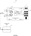
- FIG. 1 depicts a system architecture 100 for suppressing noise produced by one or more fire/smoke detection units, according to an exemplary embodiment of the invention.
- the one or more fire/smoke detection units 102 are installed in a premises 108.
- the fire/smoke detection units 102 comprises one or more fans 104 for drawing air from the premises 108 or from surroundings.
- the air is drawn by the one or more fans 104 through an inlet conduit 106A coupled/attached with the one or more fans 104.
- the conduit/s 106A may provide the air to a dust filter and then to a fire/smoke chamber 110 that detects presence of fire/smoke particles in the air.
- the detection of presence of fire/smoke particles in the air may be performed by light scattered by the fire/smoke particles in the air.
- the fire/smoke chamber 110 of the fire/smoke detection units 102 detects that the fire/smoke particles present in the air are above a specified threshold, then, the fire/smoke detection units 102 may raise an alarm to notify people present in the premises 108.
- the air may exit the fire/smoke detection units 102 through an exhaust conduit 106B coupled/attached with the one or more fans 104 as shown in the Figure 1 .
- the other methods of detecting the smoke/fire are also within the scope of the present invention.
- a noise cancellation unit 112 is used that is communicably coupled with the fire/smoke detection units 102. The details of how different components of the noise cancellation unit 112 suppresses the noise has been explained in Figure 2 .
- Figure 1 depicts that the fire/smoke detection units 102 outside the premises 108; however; it is understood by a person killed in the art that the fire/smoke detection units 102 is installed inside or outside or at any place relative to the premises 108.
- Figure 1 depicts only one fan 104 in the premises 108; however; it is understood by a person killed in the art that the premises 108 may have any number of fans installed at several places of the premises 108.
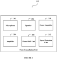
- Figure 2 depicts a block diagram of different components of a noise cancellation unit 112 communicably coupled with fire/smoke detection units 102 for suppressing noise produced by one or more fans 104 of the fire/smoke detection units 102 according to an exemplary embodiment of the invention.
- the noise cancellation unit 112 may comprise of, but is not limited to, a microphone 202, an amplifier 204, a speaker 206, a phase-shift unit 208 a power amplifier 210 and/or a speed detection unit 212.
- the microphone 202 is adapted to receive the noise from the one or more fans 104 as an input.
- the microphone 202 and the one or more fans 104 are located in proximity with each other so that the microphone 202 receive the noise from the one or more fans 104 as an input.
- the microphone 202 is adapted to derive a noise signal and provide the noise signal to the amplifier 204 and/or the speed detection unit 212 of the noise cancellation unit 112.
- the speed detection unit 212 is adapted to detect a speed of the one or more fans 104 of the fire/smoke detection unit 102.
- the speed of the one or more fans 104 may be detected based on an amplitude or a frequency of the noise signal as derived by the microphone 202. For an instance, the speed of a fan may be determined as 30 rotations per minute.
- the amplifier 204 is adapted to amplify the noise signal received from the microphone 202. In an exemplary embodiment, the amplifier 204 may amplify an amplitude of the noise signal. After amplifying the noise signal, the amplifier 204 is adapted to output an amplified noise signal and is also adapted to provide the amplified noise signal to a phase-shift unit 208.
- the phase-shift unit 208 is adapted to shift a phase of the amplified noise signal to produce an anti-phase noise signal. In an exemplary embodiment, the phase-shift unit 208 may shift or change a phase of the amplified noise signal by 180 degrees.
- phase-shift unit 208 may shift or change a phase of the amplified noise signal in such a way that the anti-phase noise signal is an inverted image of the noise signal.
- the amplification of the noise signal and phase shifting of the amplified noise signal has been explained in Figure 3 with an example.
- the anti-phase noise signal is dependent on the detected speed of the one or more fans 104 of the fire/smoke detection unit 102.
- the phase-shift unit 208 produces a phase shifted anti-phase noise signal based on the detected speed of the one or more fans 104.
- the detected speed of the one or more fans 104 may be mapped with the amplitude and/or frequency of the anti-phase noise signal as the amplitude and/or the frequency of the fans 104 are effected by speed of the fans 104.
- the anti-phase noise signal may be produced in such a way that the anti-phase noise signal (when outputted) should be able to suppress the noise made by the fan in each rotation per minute.
- the amplitude of the anti-phase noise signal may be calculated as 80 decibels (dB) to suppress the noise.
- the phase-shift unit 208 may also be adapted to provide the anti-phase noise signal to the speaker 206.
- the speaker 206 is adapted to output the anti-phase noise signal received from the phase-shift unit 208.
- the speaker 206 may output the anti-phase noise signal as sound.
- the speaker 206 and the one or more fans 104 are also located in proximity with each other in order to suppress the noise produced by the one or more fans 104 of the fire/smoke detection unit 102.
- the phase-shift unit 208 may also be adapted to provide the anti-phase noise signal to the power amplifier 210.
- the power amplifier 210 may be adapted to amplify the anti-phase noise signal received from the phase-shift unit 208.
- the power amplifier 210 may amplify a frequency of the anti-phase noise signal.
- the power amplifier 210 may amplify an amplitude of the anti-phase noise signal.
- the amplification of the anti-phase noise signal may also be dependent on speed of the one or more fans 104.
- the anti-phase noise signal may be amplified by the power amplifier 210 in such a way that the anti-phase noise signal (when outputted) should be able to suppress the noise made by a fan 104 in each rotation per minute.
- the power amplifier 210 may be adapted to output an amplified anti-phase noise signal and may also be adapted to provide the amplified anti-phase noise signal to the speaker 206.
- the speaker 206 is adapted to output the anti-phase noise signal received from the phase-shift unit. This would cancel/suppress the noise produced by the one or more fans 104 of the fire/smoke detection unit 102.
- the different units described herein are exemplary.
- the invention may be performed using one or more units.
- the tasks executed by the microphone 202, the amplifier 204, the speaker 206, the phase-shift unit 208, the power amplifier 210 and/or the speed detection unit 212 may be performed by a single unit.
- more number of units as described herein may be used to perform the invention.
- Figure 3A depicts an exemplary noise signal
- Figure 3B depicts an exemplary amplified noise signals amplified by amplitude
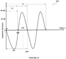
- Figure 3C depict exemplary anti-phase noise signal according to an exemplary embodiment of the invention.
- the exemplary noise signal 300A in Figure 3A has a single frequency (i.e. "f") in one cycle of 360 degree. At 180 degree, the exemplary noise signal 300A has f/2 as frequency.
- the amplified noise signal 300B is produced when the amplifier 204 amplifies the exemplary noise signal 300A by amplitude.
- the exemplary amplified noise signal 300B has 80 decibels (dB) measured as amplitude whereas the exemplary noise signal 300A has 40 decibels (dB) measured as amplitude.
- the exemplary amplified noise signal 300B (by amplitude) is phase-shifted by 180 degrees by a phase-shift unit 208, the exemplary anti-phase noise signal 300C is produced by the phase-shift unit 208.
- the exemplary anti-phase noise signal 300C is an inverted image of the exemplary amplified noise signal 300B.
- the amplifier 204 may amplify the exemplary noise signal 300A based on a threshold value of amplitude that would be required to suppress the noise produced by the one or more fans 104. Such threshold value may be automatically determined by the amplifier 204 on analyzing the exemplary noise signal 300A and by taking the speed of the one or more fans 104 into consideration. Accordingly, the amplifier 204 may amplify the exemplary noise signal 300A to increase power of the exemplary noise signal 300A.
- Figure 4 depicts a flowchart outlining the features of the invention in an exemplary embodiment of the invention.
- the method flowchart 400 describes a method for suppressing noise produced by a fire/smoke detection unit/s 102.
- the method flowchart 400 starts at step 402.
- microphone/s 202 of a noise cancellation unit 112 receives noise as an input from one or more fans 104 of a fire/smoke detection unit 102.
- the microphone 202 of the noise cancellation unit 112 derives a noise signal from the noise produced by the one or more fans 104 while drawing air from surroundings.
- a speed detection unit 212 of the noise cancellation unit 112 detects a speed of the one or more fans 104 as discussed above.
- an amplifier 204 of the noise cancellation unit 112 amplifies the noise signal received from the microphone 202.
- the amplifier 204 amplifys a frequency of the noise signal as illustrated in Figure 3C .
- the amplifier 204 amplifies an amplitude of the noise signal as illustrated in Figure 3B .
- the amplifier 204 outputs an amplified noise signal and provides the amplified noise signal to a phase-shift unit 208.
- the phase-shift unit 208 of the noise cancellation unit 112 shifts a phase of the amplified noise signal to produce an anti-phase noise signal.
- the phase-shift unit 208 may shift or change a phase of the amplified noise signal by 180 degrees. Further, the phase-shift unit 208 may shift or change a phase of the amplified noise signal in such a way that the anti-phase noise signal is an inverted image of the amplified noise signal. Also, the phase-shift unit 208 provides the anti-phase noise signal to a speaker 206.
- the anti-phase noise signal is also dependent on the detected speed of the one or more fans 104 as explained above.
- the speaker 206 of the noise cancellation unit 112 outputs the anti-phase noise signal received from the phase-shift unit 208.
- the speaker 206 may output the anti-phase noise signal as sound. This would suppress the noise produced by the one or more fans 104 of the fire/smoke detection unit 102. Then, the method flowchart 400 ends at 414.
- the present invention is applicable to various fields such as, but not limited to, hospitality industry, museums, libraries, colleges, universities, hospitals, offices and any such building that is well known in the art and where the fire/smoke detection unit produces noise which needs to be suppressed.
- the present invention provides the following technical advantages over the existing solutions a) suppresses noise produced by fan/s of fire/smoke detection unit, b) usage of a noise cancellation unit along with the fire/smoke detection unit to suppress noise produced by fan/s, and c) eliminates discomfort and disturbance caused to people because of noise produced by fan/s, d) automated way to reduce noise produced by fan/s.
Landscapes
- Physics & Mathematics (AREA)
- Engineering & Computer Science (AREA)
- Acoustics & Sound (AREA)
- Multimedia (AREA)
- Chemical & Material Sciences (AREA)
- Analytical Chemistry (AREA)
- Business, Economics & Management (AREA)
- Emergency Management (AREA)
- General Physics & Mathematics (AREA)
- Power Engineering (AREA)
- Fire-Detection Mechanisms (AREA)
- Soundproofing, Sound Blocking, And Sound Damping (AREA)
Claims (14)
- System (100), das die folgenden Bestandteile umfasst:- eine Feuer-/Rauchdetektionseinheit (102) umfassend:wobei das System (100) dadurch gekennzeichnet ist, dass es ferner umfasst:
ein Ventilator (104), der geeignet ist, Luft durch eine Leitung anzusaugen, wobei der Ventilator (104) beim Ansaugen der Luft Geräusche erzeugt;- eine Geräuschunterdrückungseinheit (112), die kommunizierend mit der Feuer-/Rauchdetektionseinheit (102) gekoppelt ist, wobei die Geräuschunterdrückungseinheit (112) folgendes umfasst:ein Mikrofon (202), das geeignet ist, das Geräusch des Ventilators (104) zu empfangen, und ein Geräuschsignal aus dem Geräusch herleitet;eine Drehzahlerfassungseinheit (212) zum Erfassen der Drehzahl des Ventilators (104);einen Verstärker (204), der geeignet ist, das von dem Mikrofon (202) empfangene Geräuschsignal zu verstärken;eine Phasenverschiebungseinheit (208), die geeignet ist, eine Phase des vom Verstärker empfangenen verstärkten Geräuschsignals zu verschieben, um ein gegenphasiges Geräuschsignal zu erzeugen, wobei das gegenphasige Geräuschsignal von der erfassten Geschwindigkeit des Ventilators (104) abhängt; undeinen Lautsprecher (206), der geeignet ist, das von der Phasenverschiebungseinheit empfangene gegenphasige Geräuschsignal auszugeben,wobei eine Amplitude des gegenphasigen Geräuschsignals auf der Drehzahl des Lüfters (104) beruht. - System nach Anspruch 1, wobei das gegenphasige Geräuschsignal das von dem Gebläse (104) der Feuer-/Rauchdetektionseinheit (102) erzeugte Geräusch unterdrückt.
- System nach Anspruch 1, wobei das Geräuschsignal und das gegenphasige Geräuschsignal um 180 Grad zueinander phasenverschoben sind.
- System nach Anspruch 1, wobei der Verstärker (204) das Geräuschsignal auf der Grundlage eines Schwellenwerts verstärkt, der erforderlich ist, um das vom Ventilator (104) erzeugte Geräusch zu unterdrücken.
- System nach Anspruch 1, wobei die Geräuschunterdrückungseinheit (112) einen Leistungsverstärker (210) umfasst, um das von der Phasenverschiebungseinheit (208) erzeugte gegenphasige Geräuschsignal zu verstärken.
- System nach Anspruch 1, wobei der Ventilator (104) und die Leitung mit der Feuer-/Rauchdetektionseinheit (102) gekoppelt sind.
- System nach Anspruch 1, bei dem die Feuer-/Rauchdetektionseinheit (102) innerhalb eines Gebäudes (108) angeordnet ist.
- System nach Anspruch 1, bei dem die Drehzahl des Ventilators der Frequenz/Amplitude des gegenphasigen Geräuschsignals zugeordnet ist.
- Verfahren, das folgendes umfasst:- Empfangen eines Geräuschs durch ein Mikrofon (202) und Herleiten eines Geräuschsignals aus dem Geräusch, wobei das Geräusch von einem Ventilator (104) einer Feuer-/Rauchdetektionseinheit (102) beim Ansaugen von Luft erzeugt wird;- Erfassen der Drehzahl des Ventilators (104) der Feuer-/Rauchdetektionseinheit (102);- Verstärken des von dem Mikrofon (202) empfangenen Geräuschsignals durch den Verstärker (204);- Erzeugen eines gegenphasigen Geräuschsignals durch Verschieben einer Phase des von dem Verstärker (204) verstärkten empfangenen Geräuschsignals, wobei das gegenphasige Geräuschsignal von der erfassten Drehzahl des Ventilators (104) abhängt; und- Ausgeben des gegenphasiges Geräuschsignals über einen Lautsprecher (206),wobei eine Amplitude des gegenphasigen Geräuschsignals auf der Drehzahl des Lüfters (104) beruht.
- Verfahren nach Anspruch 9, wobei das gegenphasige Geräuschsignal das vom Ventilator (104) der Feuer-/Rauchdetektionseinheit (102) erzeugte Geräusch unterdrückt.
- Verfahren nach Anspruch 9, wobei das Geräuschsignal und das gegenphasige Geräuschsignal eine Phasenverschiebung um 180 Grad zueinander aufweisen.
- Verfahren nach Anspruch 9, wobei der Verstärker (204) das Geräuschsignal auf der Grundlage eines Schwellenwerts verstärkt, der erforderlich ist, um das von dem Ventilator (104) erzeugte Geräusch zu unterdrücken.
- Verfahren nach Anspruch 9, wobei das von der Phasenverschiebungseinheit (208) erzeugte gegenphasige Geräuschsignal durch einen Leistungsverstärker (210) verstärkt wird.
- Verfahren nach Anspruch 9, wobei der Ventilator (104) Luft durch eine mit der Feuer-/Rauchdetektionseinheit (102) gekoppelte Leitung ansaugt.
Priority Applications (2)
| Application Number | Priority Date | Filing Date | Title |
|---|---|---|---|
| EP19383009.8A EP3822933B1 (de) | 2019-11-15 | 2019-11-15 | Verfahren und system zur rauschunterdrückung |
| US17/097,264 US11508352B2 (en) | 2019-11-15 | 2020-11-13 | Method and system for noise suppression |
Applications Claiming Priority (1)
| Application Number | Priority Date | Filing Date | Title |
|---|---|---|---|
| EP19383009.8A EP3822933B1 (de) | 2019-11-15 | 2019-11-15 | Verfahren und system zur rauschunterdrückung |
Publications (2)
| Publication Number | Publication Date |
|---|---|
| EP3822933A1 EP3822933A1 (de) | 2021-05-19 |
| EP3822933B1 true EP3822933B1 (de) | 2025-06-25 |
Family
ID=68610148
Family Applications (1)
| Application Number | Title | Priority Date | Filing Date |
|---|---|---|---|
| EP19383009.8A Active EP3822933B1 (de) | 2019-11-15 | 2019-11-15 | Verfahren und system zur rauschunterdrückung |
Country Status (2)
| Country | Link |
|---|---|
| US (1) | US11508352B2 (de) |
| EP (1) | EP3822933B1 (de) |
Citations (1)
| Publication number | Priority date | Publication date | Assignee | Title |
|---|---|---|---|---|
| US20090034746A1 (en) * | 2007-08-03 | 2009-02-05 | Koichi Nozaki | Chassis with noise cancellation function, noise cancellation method, method for producing noise cancellation sound data, program for producing noise cancellation sound data, and medium |
Family Cites Families (6)
| Publication number | Priority date | Publication date | Assignee | Title |
|---|---|---|---|---|
| US5625684A (en) * | 1993-02-04 | 1997-04-29 | Local Silence, Inc. | Active noise suppression system for telephone handsets and method |
| DE60014790T2 (de) * | 1999-07-15 | 2006-02-09 | Mitsubishi Denki K.K. | Vorrichtung zum Reduzieren von Rauschen |
| JP4273926B2 (ja) * | 2003-10-29 | 2009-06-03 | 株式会社日立製作所 | 消音装置及びそれを用いたプロジェクタ装置 |
| US7693292B1 (en) * | 2005-08-16 | 2010-04-06 | Sun Microsystems, Inc. | Method and apparatus for canceling fan noise in a computer system |
| US8098166B2 (en) * | 2009-04-23 | 2012-01-17 | Honeywell International Inc. | Variable air speed aspirating smoke detector |
| CN102216980B (zh) * | 2011-05-09 | 2012-12-19 | 华为技术有限公司 | 转动装置噪声控制方法及控制器 |
-
2019
- 2019-11-15 EP EP19383009.8A patent/EP3822933B1/de active Active
-
2020
- 2020-11-13 US US17/097,264 patent/US11508352B2/en active Active
Patent Citations (1)
| Publication number | Priority date | Publication date | Assignee | Title |
|---|---|---|---|---|
| US20090034746A1 (en) * | 2007-08-03 | 2009-02-05 | Koichi Nozaki | Chassis with noise cancellation function, noise cancellation method, method for producing noise cancellation sound data, program for producing noise cancellation sound data, and medium |
Also Published As
| Publication number | Publication date |
|---|---|
| EP3822933A1 (de) | 2021-05-19 |
| US11508352B2 (en) | 2022-11-22 |
| US20210151027A1 (en) | 2021-05-20 |
Similar Documents
| Publication | Publication Date | Title |
|---|---|---|
| EP2378133A3 (de) | Verfahren und Systeme zur aktiven Schalldämpfung in einer Lüftereinheit | |
| US20150003621A1 (en) | Personal noise reduction method for enclosed cabins | |
| JP2010244045A (ja) | オーディオシステム出力に基づくアクティブノイズ制御システム | |
| JPWO2011052088A1 (ja) | 騒音制御システム、並びに、それを搭載したファン構造体及び空気調和機の室外機 | |
| KR20210015619A (ko) | 소음 제거 장치 및 방법 | |
| EP2106163A3 (de) | Vorrichtung und Verfahren zur dynamischen Detektion und Dämpfung von periodischer Schallrückkopllung | |
| KR102452256B1 (ko) | 실내 저-주파수 사운드 파워 최적화를 위한 방법 및 장치 | |
| JPS59500536A (ja) | 光フアイバ音響変換器を用いた侵入検出装置 | |
| JP5607997B2 (ja) | ノイズキャンセルヘッドホンのための安定動作検査装置 | |
| US9473864B2 (en) | Internet protocol addressable public address devices and systems | |
| KR101774320B1 (ko) | 층간 소음 억제 시스템 및 그 방법 | |
| US11508352B2 (en) | Method and system for noise suppression | |
| US7315244B2 (en) | Excessive noise level alerting device | |
| CN104658193B (zh) | 利用跟随有语音识别的传入可听命令的处理的周围条件检测器 | |
| JP2000155048A (ja) | 音源寄与解析方法 | |
| WO2019220760A1 (ja) | 測位システム、空調システム、端末装置、位置推定装置、位置推定方法、音波出力方法、プログラム | |
| JP2014055783A (ja) | 動作音検出装置およびその動作方法 | |
| JPH06214575A (ja) | 吸音装置 | |
| JP2005080303A (ja) | オーディオトランスデューサ用音声マッチングシステム | |
| JP5151941B2 (ja) | 音響装置 | |
| JP7003023B2 (ja) | 金属検出装置 | |
| JP2021536692A (ja) | ヒューマンマシン音声対話装置及びその操作方法 | |
| JP2006185225A (ja) | 警報装置識別装置、システムおよび方法 | |
| US9157996B1 (en) | Multiple ultrasonic preamplifiers with independent automatic gain control | |
| JPH09179565A (ja) | 騒音低減装置 |
Legal Events
| Date | Code | Title | Description |
|---|---|---|---|
| PUAI | Public reference made under article 153(3) epc to a published international application that has entered the european phase |
Free format text: ORIGINAL CODE: 0009012 |
|
| STAA | Information on the status of an ep patent application or granted ep patent |
Free format text: STATUS: THE APPLICATION HAS BEEN PUBLISHED |
|
| AK | Designated contracting states |
Kind code of ref document: A1 Designated state(s): AL AT BE BG CH CY CZ DE DK EE ES FI FR GB GR HR HU IE IS IT LI LT LU LV MC MK MT NL NO PL PT RO RS SE SI SK SM TR |
|
| STAA | Information on the status of an ep patent application or granted ep patent |
Free format text: STATUS: REQUEST FOR EXAMINATION WAS MADE |
|
| 17P | Request for examination filed |
Effective date: 20211118 |
|
| RBV | Designated contracting states (corrected) |
Designated state(s): AL AT BE BG CH CY CZ DE DK EE ES FI FR GB GR HR HU IE IS IT LI LT LU LV MC MK MT NL NO PL PT RO RS SE SI SK SM TR |
|
| STAA | Information on the status of an ep patent application or granted ep patent |
Free format text: STATUS: EXAMINATION IS IN PROGRESS |
|
| 17Q | First examination report despatched |
Effective date: 20220916 |
|
| GRAP | Despatch of communication of intention to grant a patent |
Free format text: ORIGINAL CODE: EPIDOSNIGR1 |
|
| STAA | Information on the status of an ep patent application or granted ep patent |
Free format text: STATUS: GRANT OF PATENT IS INTENDED |
|
| INTG | Intention to grant announced |
Effective date: 20241029 |
|
| GRAS | Grant fee paid |
Free format text: ORIGINAL CODE: EPIDOSNIGR3 |
|
| GRAA | (expected) grant |
Free format text: ORIGINAL CODE: 0009210 |
|
| STAA | Information on the status of an ep patent application or granted ep patent |
Free format text: STATUS: THE PATENT HAS BEEN GRANTED |
|
| AK | Designated contracting states |
Kind code of ref document: B1 Designated state(s): AL AT BE BG CH CY CZ DE DK EE ES FI FR GB GR HR HU IE IS IT LI LT LU LV MC MK MT NL NO PL PT RO RS SE SI SK SM TR |
|
| REG | Reference to a national code |
Ref country code: GB Ref legal event code: FG4D |
|
| REG | Reference to a national code |
Ref country code: CH Ref legal event code: EP |
|
| REG | Reference to a national code |
Ref country code: CH Ref legal event code: EP |
|
| REG | Reference to a national code |
Ref country code: IE Ref legal event code: FG4D |
|
| REG | Reference to a national code |
Ref country code: DE Ref legal event code: R096 Ref document number: 602019071496 Country of ref document: DE |
|
| PG25 | Lapsed in a contracting state [announced via postgrant information from national office to epo] |
Ref country code: FI Free format text: LAPSE BECAUSE OF FAILURE TO SUBMIT A TRANSLATION OF THE DESCRIPTION OR TO PAY THE FEE WITHIN THE PRESCRIBED TIME-LIMIT Effective date: 20250625 |
|
| REG | Reference to a national code |
Ref country code: LT Ref legal event code: MG9D |
|
| PG25 | Lapsed in a contracting state [announced via postgrant information from national office to epo] |
Ref country code: NO Free format text: LAPSE BECAUSE OF FAILURE TO SUBMIT A TRANSLATION OF THE DESCRIPTION OR TO PAY THE FEE WITHIN THE PRESCRIBED TIME-LIMIT Effective date: 20250925 Ref country code: GR Free format text: LAPSE BECAUSE OF FAILURE TO SUBMIT A TRANSLATION OF THE DESCRIPTION OR TO PAY THE FEE WITHIN THE PRESCRIBED TIME-LIMIT Effective date: 20250926 |
|
| PG25 | Lapsed in a contracting state [announced via postgrant information from national office to epo] |
Ref country code: BG Free format text: LAPSE BECAUSE OF FAILURE TO SUBMIT A TRANSLATION OF THE DESCRIPTION OR TO PAY THE FEE WITHIN THE PRESCRIBED TIME-LIMIT Effective date: 20250625 |
|
| PG25 | Lapsed in a contracting state [announced via postgrant information from national office to epo] |
Ref country code: HR Free format text: LAPSE BECAUSE OF FAILURE TO SUBMIT A TRANSLATION OF THE DESCRIPTION OR TO PAY THE FEE WITHIN THE PRESCRIBED TIME-LIMIT Effective date: 20250625 |
|
| PG25 | Lapsed in a contracting state [announced via postgrant information from national office to epo] |
Ref country code: RS Free format text: LAPSE BECAUSE OF FAILURE TO SUBMIT A TRANSLATION OF THE DESCRIPTION OR TO PAY THE FEE WITHIN THE PRESCRIBED TIME-LIMIT Effective date: 20250925 |
|
| PG25 | Lapsed in a contracting state [announced via postgrant information from national office to epo] |
Ref country code: LV Free format text: LAPSE BECAUSE OF FAILURE TO SUBMIT A TRANSLATION OF THE DESCRIPTION OR TO PAY THE FEE WITHIN THE PRESCRIBED TIME-LIMIT Effective date: 20250625 |
|
| REG | Reference to a national code |
Ref country code: NL Ref legal event code: MP Effective date: 20250625 |
|
| PG25 | Lapsed in a contracting state [announced via postgrant information from national office to epo] |
Ref country code: NL Free format text: LAPSE BECAUSE OF FAILURE TO SUBMIT A TRANSLATION OF THE DESCRIPTION OR TO PAY THE FEE WITHIN THE PRESCRIBED TIME-LIMIT Effective date: 20250625 |
|
| PG25 | Lapsed in a contracting state [announced via postgrant information from national office to epo] |
Ref country code: PT Free format text: LAPSE BECAUSE OF FAILURE TO SUBMIT A TRANSLATION OF THE DESCRIPTION OR TO PAY THE FEE WITHIN THE PRESCRIBED TIME-LIMIT Effective date: 20251027 |
|
| REG | Reference to a national code |
Ref country code: AT Ref legal event code: MK05 Ref document number: 1807362 Country of ref document: AT Kind code of ref document: T Effective date: 20250625 |
|
| PG25 | Lapsed in a contracting state [announced via postgrant information from national office to epo] |
Ref country code: IS Free format text: LAPSE BECAUSE OF FAILURE TO SUBMIT A TRANSLATION OF THE DESCRIPTION OR TO PAY THE FEE WITHIN THE PRESCRIBED TIME-LIMIT Effective date: 20251025 |
|
| PGFP | Annual fee paid to national office [announced via postgrant information from national office to epo] |
Ref country code: DE Payment date: 20251022 Year of fee payment: 7 |
|
| PGFP | Annual fee paid to national office [announced via postgrant information from national office to epo] |
Ref country code: GB Payment date: 20251023 Year of fee payment: 7 |
|
| PG25 | Lapsed in a contracting state [announced via postgrant information from national office to epo] |
Ref country code: SM Free format text: LAPSE BECAUSE OF FAILURE TO SUBMIT A TRANSLATION OF THE DESCRIPTION OR TO PAY THE FEE WITHIN THE PRESCRIBED TIME-LIMIT Effective date: 20250625 Ref country code: AT Free format text: LAPSE BECAUSE OF FAILURE TO SUBMIT A TRANSLATION OF THE DESCRIPTION OR TO PAY THE FEE WITHIN THE PRESCRIBED TIME-LIMIT Effective date: 20250625 |
|
| PGFP | Annual fee paid to national office [announced via postgrant information from national office to epo] |
Ref country code: FR Payment date: 20251022 Year of fee payment: 7 |
|
| PG25 | Lapsed in a contracting state [announced via postgrant information from national office to epo] |
Ref country code: CZ Free format text: LAPSE BECAUSE OF FAILURE TO SUBMIT A TRANSLATION OF THE DESCRIPTION OR TO PAY THE FEE WITHIN THE PRESCRIBED TIME-LIMIT Effective date: 20250625 |
|
| PG25 | Lapsed in a contracting state [announced via postgrant information from national office to epo] |
Ref country code: PL Free format text: LAPSE BECAUSE OF FAILURE TO SUBMIT A TRANSLATION OF THE DESCRIPTION OR TO PAY THE FEE WITHIN THE PRESCRIBED TIME-LIMIT Effective date: 20250625 |
|
| PG25 | Lapsed in a contracting state [announced via postgrant information from national office to epo] |
Ref country code: EE Free format text: LAPSE BECAUSE OF FAILURE TO SUBMIT A TRANSLATION OF THE DESCRIPTION OR TO PAY THE FEE WITHIN THE PRESCRIBED TIME-LIMIT Effective date: 20250625 |
|
| PG25 | Lapsed in a contracting state [announced via postgrant information from national office to epo] |
Ref country code: SK Free format text: LAPSE BECAUSE OF FAILURE TO SUBMIT A TRANSLATION OF THE DESCRIPTION OR TO PAY THE FEE WITHIN THE PRESCRIBED TIME-LIMIT Effective date: 20250625 |
|
| PG25 | Lapsed in a contracting state [announced via postgrant information from national office to epo] |
Ref country code: ES Free format text: LAPSE BECAUSE OF FAILURE TO SUBMIT A TRANSLATION OF THE DESCRIPTION OR TO PAY THE FEE WITHIN THE PRESCRIBED TIME-LIMIT Effective date: 20250625 |
|
| PG25 | Lapsed in a contracting state [announced via postgrant information from national office to epo] |
Ref country code: RO Free format text: LAPSE BECAUSE OF FAILURE TO SUBMIT A TRANSLATION OF THE DESCRIPTION OR TO PAY THE FEE WITHIN THE PRESCRIBED TIME-LIMIT Effective date: 20250625 |
|
| REG | Reference to a national code |
Ref country code: DE Ref legal event code: R097 Ref document number: 602019071496 Country of ref document: DE |
|
| PG25 | Lapsed in a contracting state [announced via postgrant information from national office to epo] |
Ref country code: DK Free format text: LAPSE BECAUSE OF FAILURE TO SUBMIT A TRANSLATION OF THE DESCRIPTION OR TO PAY THE FEE WITHIN THE PRESCRIBED TIME-LIMIT Effective date: 20250625 |
|
| PG25 | Lapsed in a contracting state [announced via postgrant information from national office to epo] |
Ref country code: IT Free format text: LAPSE BECAUSE OF FAILURE TO SUBMIT A TRANSLATION OF THE DESCRIPTION OR TO PAY THE FEE WITHIN THE PRESCRIBED TIME-LIMIT Effective date: 20250625 |
|
| PLBE | No opposition filed within time limit |
Free format text: ORIGINAL CODE: 0009261 |
|
| STAA | Information on the status of an ep patent application or granted ep patent |
Free format text: STATUS: NO OPPOSITION FILED WITHIN TIME LIMIT |
|
| REG | Reference to a national code |
Ref country code: CH Ref legal event code: L10 Free format text: ST27 STATUS EVENT CODE: U-0-0-L10-L00 (AS PROVIDED BY THE NATIONAL OFFICE) Effective date: 20260507 |
|
| 26N | No opposition filed |
Effective date: 20260326 |
|
| REG | Reference to a national code |
Ref country code: CH Ref legal event code: H13 Free format text: ST27 STATUS EVENT CODE: U-0-0-H10-H13 (AS PROVIDED BY THE NATIONAL OFFICE) Effective date: 20260623 |
|
| PG25 | Lapsed in a contracting state [announced via postgrant information from national office to epo] |
Ref country code: LT Free format text: LAPSE BECAUSE OF FAILURE TO SUBMIT A TRANSLATION OF THE DESCRIPTION OR TO PAY THE FEE WITHIN THE PRESCRIBED TIME-LIMIT Effective date: 20250625 |
|
| PG25 | Lapsed in a contracting state [announced via postgrant information from national office to epo] |
Ref country code: MC Free format text: LAPSE BECAUSE OF FAILURE TO SUBMIT A TRANSLATION OF THE DESCRIPTION OR TO PAY THE FEE WITHIN THE PRESCRIBED TIME-LIMIT Effective date: 20250625 |
|
| PG25 | Lapsed in a contracting state [announced via postgrant information from national office to epo] |
Ref country code: CH Free format text: LAPSE BECAUSE OF NON-PAYMENT OF DUE FEES Effective date: 20251130 Ref country code: LU Free format text: LAPSE BECAUSE OF NON-PAYMENT OF DUE FEES Effective date: 20251115 |
|
| PG25 | Lapsed in a contracting state [announced via postgrant information from national office to epo] |
Ref country code: SE Free format text: LAPSE BECAUSE OF FAILURE TO SUBMIT A TRANSLATION OF THE DESCRIPTION OR TO PAY THE FEE WITHIN THE PRESCRIBED TIME-LIMIT Effective date: 20250625 |