EP3823005B1 - Microscope électronique à transmission et son procédé de commande - Google Patents
Microscope électronique à transmission et son procédé de commande Download PDFInfo
- Publication number
- EP3823005B1 EP3823005B1 EP20207560.2A EP20207560A EP3823005B1 EP 3823005 B1 EP3823005 B1 EP 3823005B1 EP 20207560 A EP20207560 A EP 20207560A EP 3823005 B1 EP3823005 B1 EP 3823005B1
- Authority
- EP
- European Patent Office
- Prior art keywords
- condenser
- condenser lens
- lens
- electron beam
- optical system
- Prior art date
- Legal status (The legal status is an assumption and is not a legal conclusion. Google has not performed a legal analysis and makes no representation as to the accuracy of the status listed.)
- Active
Links
Images



Classifications
-
- H—ELECTRICITY
- H01—ELECTRIC ELEMENTS
- H01J—ELECTRIC DISCHARGE TUBES OR DISCHARGE LAMPS
- H01J37/00—Discharge tubes with provision for introducing objects or material to be exposed to the discharge, e.g. for the purpose of examination or processing thereof
- H01J37/26—Electron or ion microscopes; Electron or ion diffraction tubes
- H01J37/28—Electron or ion microscopes; Electron or ion diffraction tubes with scanning beams
-
- H—ELECTRICITY
- H01—ELECTRIC ELEMENTS
- H01J—ELECTRIC DISCHARGE TUBES OR DISCHARGE LAMPS
- H01J37/00—Discharge tubes with provision for introducing objects or material to be exposed to the discharge, e.g. for the purpose of examination or processing thereof
- H01J37/26—Electron or ion microscopes; Electron or ion diffraction tubes
- H01J37/261—Details
-
- H—ELECTRICITY
- H01—ELECTRIC ELEMENTS
- H01J—ELECTRIC DISCHARGE TUBES OR DISCHARGE LAMPS
- H01J37/00—Discharge tubes with provision for introducing objects or material to be exposed to the discharge, e.g. for the purpose of examination or processing thereof
- H01J37/02—Details
- H01J37/04—Arrangements of electrodes and associated parts for generating or controlling the discharge, e.g. electron-optical arrangement or ion-optical arrangement
- H01J37/09—Diaphragms; Shields associated with electron or ion-optical arrangements; Compensation of disturbing fields
-
- H—ELECTRICITY
- H01—ELECTRIC ELEMENTS
- H01J—ELECTRIC DISCHARGE TUBES OR DISCHARGE LAMPS
- H01J37/00—Discharge tubes with provision for introducing objects or material to be exposed to the discharge, e.g. for the purpose of examination or processing thereof
- H01J37/02—Details
- H01J37/04—Arrangements of electrodes and associated parts for generating or controlling the discharge, e.g. electron-optical arrangement or ion-optical arrangement
- H01J37/153—Electron-optical or ion-optical arrangements for the correction of image defects, e.g. stigmators
-
- H—ELECTRICITY
- H01—ELECTRIC ELEMENTS
- H01J—ELECTRIC DISCHARGE TUBES OR DISCHARGE LAMPS
- H01J37/00—Discharge tubes with provision for introducing objects or material to be exposed to the discharge, e.g. for the purpose of examination or processing thereof
- H01J37/30—Electron-beam or ion-beam tubes for localised treatment of objects
- H01J37/3002—Details
- H01J37/3007—Electron or ion-optical systems
-
- H—ELECTRICITY
- H01—ELECTRIC ELEMENTS
- H01J—ELECTRIC DISCHARGE TUBES OR DISCHARGE LAMPS
- H01J2237/00—Discharge tubes exposing object to beam, e.g. for analysis treatment, etching, imaging
- H01J2237/04—Means for controlling the discharge
- H01J2237/045—Diaphragms
- H01J2237/0451—Diaphragms with fixed aperture
-
- H—ELECTRICITY
- H01—ELECTRIC ELEMENTS
- H01J—ELECTRIC DISCHARGE TUBES OR DISCHARGE LAMPS
- H01J2237/00—Discharge tubes exposing object to beam, e.g. for analysis treatment, etching, imaging
- H01J2237/04—Means for controlling the discharge
- H01J2237/049—Focusing means
- H01J2237/0492—Lens systems
-
- H—ELECTRICITY
- H01—ELECTRIC ELEMENTS
- H01J—ELECTRIC DISCHARGE TUBES OR DISCHARGE LAMPS
- H01J2237/00—Discharge tubes exposing object to beam, e.g. for analysis treatment, etching, imaging
- H01J2237/10—Lenses
- H01J2237/103—Lenses characterised by lens type
-
- H—ELECTRICITY
- H01—ELECTRIC ELEMENTS
- H01J—ELECTRIC DISCHARGE TUBES OR DISCHARGE LAMPS
- H01J2237/00—Discharge tubes exposing object to beam, e.g. for analysis treatment, etching, imaging
- H01J2237/26—Electron or ion microscopes
- H01J2237/28—Scanning microscopes
- H01J2237/2802—Transmission microscopes
Definitions
- the present invention relates to a transmission electron microscope (TEM) and to a method of controlling it.
- TEM transmission electron microscope
- An optical system having at least two stages of condenser lenses interlockingly excitable and capable of permitting electron source images focused by the condenser lenses to be set at plural positions is disclosed as a TEM illumination optical system, for example, in patent document 1.
- a TEM illumination optical system for example, in patent document 1.
- a TEM illumination optical system which has three stages of condenser lenses. Furthermore, a TEM illumination optical system having four stages of condenser lenses is known.
- a sample is illuminated with parallel electron rays (known as parallel illumination).
- parallel illumination the sample can be illuminated with parallel electron rays by making the electron beam source and the front focal plane of the objective lens conjugate with each other (known as Kohler illumination). Further reference is made to patent document 2.
- the illumination optical system of a transmission electron microscope includes a condenser aperture for adjusting the angular aperture and dose of the electron beam. It is known that in a transmission electron microscope, Fresnel fringes are produced around the edge of the condenser aperture because of defocus of the condenser aperture in the sample plane. Under normal imaging conditions, the area of the illumination coverage provided by the electron beam is sufficiently wider than the field of view for imaging and, therefore, Fresnel fringes do not appear within the field of view for imaging.
- the transmission electron microscope associated with the present invention has: an electron beam source emitting an electron beam; and an illumination optical system for directing the emitted electron beam at a sample.
- the illumination optical system has a first condenser lens, a second condenser lens disposed behind the first condenser lens, a third condenser lens disposed behind the second condenser lens, a fourth condenser lens disposed behind the third condenser lens, an objective lens disposed behind the fourth condenser lens, and a condenser aperture disposed at the position of the second condenser lens.
- the third and fourth condenser lenses cooperate to make the position of the condenser aperture and a sample plane conjugate to each other.
- the first and second condenser lenses cooperate to make the electron beam source and a front focal plane of the objective lens conjugate to each other while the conjugate relationship between the position of the condenser aperture and the sample plane is maintained by the third and fourth condenser lenses.
- the position of the condenser aperture and the sample plane can be made conjugate to each other, and the electron beam source and the front focal plane of the objective lens can be made conjugate to one another. Therefore, if the sample is illuminated with parallel electron rays, it is possible to prevent Fresnel fringes of the condenser aperture from forming in the sample plane. Accordingly, in this transmission electron microscope, TEM imaging can be done by a parallel illumination of a narrow area with an electron beam.
- a control method associated with the present invention is for use in a transmission electron microscope which has: an electron beam source emitting an electron beam; and an illumination optical system for directing the emitted electron beam at a sample.
- the illumination optical system has: a first condenser lens; a second condenser lens disposed behind the first condenser lens; a third condenser lens disposed behind the second condenser lens; a fourth condenser lens disposed behind the third condenser lens; an objective lens disposed behind the fourth condenser lens; and a condenser aperture disposed at the position of the second condenser lens.
- the control method starts with setting the third and fourth condenser lenses to a first set of conditions in which the position of the condenser aperture and a sample plane are made conjugate to each other. Then, the first and second condenser lenses are set to a second set of conditions in which the electron beam source and a front focal plane of the objective lens are made conjugate to each other while the first set of conditions for the third and fourth condenser lenses is maintained.
- the position of the condenser aperture and the sample plane can be made conjugate to each other.
- the electron beam source and the front focal plane of the objective lens can be made conjugate to each other. Therefore, if the sample is illuminated with parallel electron rays, it is possible to prevent Fresnel fringes of the condenser aperture from forming in the sample plane. Consequently, this control method for the transmission electron microscope allows for TEM imaging while illuminating a narrow illumination coverage with parallel electron rays.
- FIG. 1 illustrates the configuration of the transmission electron microscope, 100, associated with the first embodiment.
- the transmission electron microscope 100 includes an electron beam source 10, an illumination optical system 20, an imaging optical system 30, an electronic imager 40, and a controller 50.
- the electron beam source 10 emits an electron beam.
- the electron beam source 10 is an electron gun which emits an electron beam by accelerating electrons, released from a cathode, by means of an anode.
- the electron beam released from the electron beam source 10 is made to impinge on a sample S by the action of the illumination optical system 20.
- the illumination optical system 20 is equipped with four stages of condenser lenses.
- the illumination optical system 20 includes a first condenser lens 21, a second condenser lens 22, a third condenser lens 23, a fourth condenser lens 24, a condenser aperture 26, and an objective lens 28.
- the first condenser lens 21 is disposed behind (i.e., downstream of) the electron beam source 10.
- the second condenser lens 22 is located behind the first condenser lens 21.
- the third condenser lens 23 is located behind the second condenser lens 22.
- the fourth condenser lens 24 is positioned behind the third condenser lens 23.
- the objective lens 28 is located behind the fourth condenser lens 24.
- the first condenser lens 21, second condenser lens 22, third condenser lens 23, fourth condenser lens 24, and objective lens 28 are arranged in this order along an optical axis L.
- the condenser aperture 26 is located at the position of the second condenser lens 22, i.e., within the second condenser lens 22.
- the functions of the illumination optical system 20 are described in detail later.
- the sample S is supported by a sample holder (not shown).
- the objective lens 28 has top and bottom polepieces between which the sample S is positioned.
- the imaging optical system 30 forms TEM (transmission electron microscopy) images from electrons transmitted through the sample S.
- the TEM images include bright field images, dark field images, and high-resolution electron microscopy (HREM) images.
- the imaging optical system 30 includes the objective lens 28, an intermediate lens 32, and a projector lens 34.
- the objective lens 28 is included in both the illumination optical system 20 and the imaging optical system 30.
- the objective lens 28 is an initial stage of lens for forming a TEM image from electrons transmitted through the sample S.
- the intermediate lens 32 is disposed behind the objective lens 28.
- the projector lens 34 is positioned behind the intermediate lens 32.
- the intermediate lens 32 focuses the TEM image formed by the objective lens 28, magnifies the focused TEM image, and forms a magnified TEM image on the object plane of the projector lens 34.
- the projector lens 34 further magnifies the TEM image magnified by the intermediate lens 32 and focuses the TEM image onto the imager 40.
- Lenses constituting the aforementioned illumination optical system 20 and lenses constituting the imaging optical system 30 are electron lenses which produce magnetic fields for focusing the electron beam, for example, by passing excitation currents through coils. With such an electron lens, its magnification factor or focal length can be varied by varying the excitation current.
- the imager 40 captures the TEM image focused by the imaging optical system 30.
- the imager 40 is a detector for detecting electrons.
- the imager 40 is a digital camera such as a CCD (charged coupled device) or CMOS (complementary metal-oxide-semiconductor) camera.
- the controller 50 controls various parts of the transmission electron microscope 100.
- the controller 50 includes a processor such as a CPU (central processing unit) and storage devices such as a RAM (random access memory) and a ROM (read only memory).
- Computer programs for performing various control operations are stored in the storage devices as well as data.
- the functions of the controller 50 can be accomplished by executing such programs by means of the processor.
- the controller 50 may further include a manual control section permitting a user to enter scanning information and a display section for displaying the captured TEM images and other images.
- FIG. 2 is an electron ray diagram illustrating the illumination optical system 20. The configuration of the illumination optical system 20 and electron rays are shown in FIG. 2 .
- the third condenser lens 23 and the fourth condenser lens 24 cooperate to make the position of the condenser aperture 26 and the sample plane 2 conjugate to each other.
- the sample plane 2 provides a position at which the sample S is placed.
- the first condenser lens 21 and the second condenser lens 22 cooperate to make the electron beam source 10 and the front focal plane 4 of the objective lens 28 conjugate to each other while the conjugate relationship is maintained between the position of the condenser aperture 26 and the sample plane 2 by the third condenser lens 23 and the fourth condenser lens 24.
- the third condenser lens 23 and the fourth condenser lens 24 are used to make the position of the condenser aperture 26 and the sample plane 2 conjugate to each other. Furthermore, the first condenser lens 21 and the second condenser lens 22 are used to make the electron beam source 10 and the front focal plane 4 of the objective lens 28 conjugate to each other.
- the first condenser lens 21 is used to vary the electron beam dose, i.e., the brightness. Furthermore, in the illumination optical system 20, the sample S can be illuminated by parallel electron rays (known as Kohler illumination) by making the electron beam source 10 and the front focal plane 4 of the objective lens 28 conjugate to each other. Also, in the illumination optical system 20, it is possible to prevent Fresnel fringes of the condenser aperture 26 from being induced in the sample plane 2 by making the position of the condenser aperture 26 and the sample plane 2 conjugate to each other.
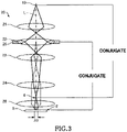
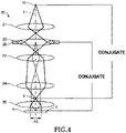
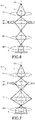
- FIGS. 3-5 illustrate the operation of the illumination optical system 20.
- FIG. 3 illustrates a case in which the illumination coverage is a first range A1.
- FIG. 4 illustrates a case in which the illumination coverage is a second range A2.
- FIG. 5 illustrates a case in which the illumination coverage is a third range A3.
- the first range A1 is narrower than the second range A2, which in turn is narrower than the third range A3.
- the illumination coverage provided by the electron beam can be varied by varying the excitations of the second condenser lens 22, third condenser lens 23, and fourth condenser lens 24 while maintaining the conjugate relationship between the position of the condenser aperture 26 and the sample plane 2 and the conjugate relationship between the electron beam source 10 and the front focal plane 4 of the objective lens 28. Consequently, an illumination optical system can be accomplished which can implement parallel illumination by electron rays without producing Fresnel fringes in the sample plane 2 and which can vary the illumination coverage. In the illumination optical system 20, no Fresnel fringes are induced in the sample plane 2 and so even a quite small illumination coverage area which is less than 1 ⁇ m in diameter, for example, can be uniformly illuminated with electron rays.
- the controller 50 sets the third condenser lens 23 and the fourth condenser lens 24 to a first set of conditions where the position of the condenser aperture 26 and the sample plane 2 are made conjugate to each other. Under this first set of conditions, the controller 50 sets the first condenser lens 21 and the second condenser lens 22 to a second set of conditions where the electron beam source 10 and the front focal plane 4 of the objective lens 28 are made conjugate to each other.
- the electron beam source 10 and the front focal plane 4 of the objective lens 28 are conjugate to each other, and the position of the condenser aperture 26 and the sample plane 2 are conjugate to each other. Consequently, the sample S can be illuminated with parallel electron rays. Also, it is possible to prevent Fresnel fringes of the condenser aperture 26 from forming in the sample plane 2.
- the controller 50 sets the operational conditions of the second condenser lens 22, third condenser lens 23, and fourth condenser lens 24 such that the illumination coverage is the first range A1 as shown in FIG. 3 while maintaining both the conjugate relationship between the position of the condenser aperture 26 and the sample plane 2 and the conjugate relationship between the electron beam source 10 and the front focal plane 4 of the objective lens 28.
- the controller 50 sets the operational conditions of the second condenser lens 22, third condenser lens 23, and fourth condenser lens 24 such that the illumination coverage provided by the electron rays is the second range A2 as shown in FIG. 4 while maintaining both the conjugate relationship between the position of the condenser aperture 26 and the sample plane 2 and the conjugate relationship between the electron beam source 10 and the front focal plane 4 of the objective lens 28.
- the controller 50 sets the operational conditions of the second condenser lens 22, third condenser lens 23, and fourth condenser lens 24 such that the illumination coverage is the third range A3 as shown in FIG. 5 while maintaining both the conjugate relationship between the position of the condenser aperture 26 and the sample plane 2 and the conjugate relationship between the electron beam source 10 and the front focal plane 4 of the objective lens 28.
- the controller 50 performs processing to vary the illumination coverage provided by the electron beam while maintaining both the conjugate relationship between the position of the condenser aperture 26 and the sample plane 2 and the conjugate relationship between the electron beam source 10 and the front focal plane 4 of the objective lens 28.
- the operational conditions of the illumination optical system 20 which set the illumination coverage provided by electron rays to the first range A1 may be previously stored in a storage section of the controller 50.
- a mathematical function or numerical table for deriving the operational conditions of the illumination optical system 20 from illumination coverages may be stored in the storage section of the controller 50.
- the controller 50 may set the operational conditions of the illumination optical system 20 from an entered illumination coverage, using operational conditions, functions, tables, or the like stored in the storage section.
- the illumination optical system 20 has the first condenser lens 21, second condenser lens 22, third condenser lens 23, fourth condenser lens 24, condenser aperture 26, and objective lens 28.
- the third condenser lens 23 and fourth condenser lens 24 operate together to make the position of the condenser aperture 26 and the sample plane 2 conjugate to each other.
- the first condenser lens 21 and the second condenser lens 22 operate together to make the electron beam source 10 and the front focal plane 4 of the objective lens 28 conjugate to each other while the conjugate relationship between the position of the condenser aperture 26 and the sample plane 2 is maintained by the third condenser lens 23 and the fourth condenser lens 24.
- the position of the condenser aperture 26 and the sample plane 2 are conjugate to each other and, therefore, it is possible to prevent Fresnel fringes of the condenser aperture 26 from being induced in the sample plane 2. Furthermore, since the electron beam source 10 and the front focal plane 4 of the objective lens 28 are conjugate to each other, the sample S can be illuminated with parallel electron rays. Accordingly, in the transmission electron microscope 100, even if the sample S is illuminated with parallel electron rays, it is possible to prevent Fresnel fringes of the condenser aperture 26 from being generated in the sample plane 2. In consequence, in the transmission electron microscope 100, TEM imaging can be performed while illuminating a narrow illumination coverage with parallel electron rays.
- the illumination coverage on the sample plane 2 provided by the electron beam can be varied by varying the excitations of the second condenser lens 22, third condenser lens 23, and fourth condenser lens 24 while maintaining both the conjugate relationship between the position of the condenser aperture 26 and the sample plane 2 and the conjugate relationship between the electron beam source 10 and the front focal plane 4 of the objective lens 28.
- the illumination optical system 20 equipped with the four stages of condenser lenses is compared below with an illumination optical system equipped with three stages of condenser lenses to thereby explain in detail the effects of the above-described transmission electron microscope 100.
- FIG. 6 is an electron ray diagram illustrating the configuration of the illumination optical system 202 of the transmission electron microscope of the Comparative Example.
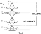
- FIGS. 7 and 8 are electron ray diagrams illustrating the operation of the illumination optical system 202 of the transmission electron microscope of the Comparative Example.
- the illumination optical system, 202, of the transmission electron microscope of the Comparative Example has three stages of condenser lenses (first condenser lens 21, second condenser lens 22, and third condenser lens 23), a condenser aperture 26, and an objective lens 28 as shown in FIG. 6 .
- the sample S can be illuminated with parallel electron rays by making the electron beam source 10 and the front focal plane 4 of the objective lens 28 conjugate to each other. Also, in the illumination optical system 202, the illumination coverage provided by the electron rays can be varied by varying the excitations of the second condenser lens 22 and third condenser lens 23 as shown in FIG. 7 .
- Fresnel fringes are produced around the edge of the condenser aperture 26. Therefore, if the illumination coverage is sufficiently wider than the field of view of the microscope, the Fresnel fringes will not appear within the field of view but, if the illumination coverage is narrowed, the Fresnel fringes will appear within the field of view of the microscope.
- the Fresnel fringes of the condenser aperture 26 are induced by defocus of the condenser aperture 26 in the sample plane 2.
- the position of the condenser aperture 26 and the sample plane 2 are not conjugate as shown in FIG. 8 . Therefore, Fresnel fringes are generated around the edge of the condenser aperture 26.
- the electron beam source 10 and the front focal plane 4 of the objective lens 28 can be made conjugate to each other and the position of the condenser aperture 26 and the sample plane 2 can be made conjugate to each other by the use of the four stages of condenser lenses. Furthermore, in the illumination optical system 20, the illumination coverage can be varied while maintaining these two conjugate relationships. Therefore, in the illumination optical system 20, the sample S can be illuminated with parallel electron rays without producing Fresnel fringes.
- the transmission electron microscope 100 As described above, in the transmission electron microscope 100, TEM observation can be performed by illuminating a narrow illumination coverage area with parallel electron rays. Therefore, the transmission electron microscope 100 is effective for use in cryoelectron microscopy for directly observing, for example, frozen samples by TEM.
- a frozen sample is observed with a transmission electron microscope
- the sample may be damaged or ice may melt in regions outside of the field of view of the microscope.
- Quantifoil Trademark Registered
- the electron beam is focused to the order of 0.5 ⁇ m in diameter.
- the Fresnel fringes produce no effect.
- a control method for the transmission electron microscope 100 involves the steps of: setting the third condenser lens 23 and the fourth condenser lens 24 to a first set of conditions in which the position of the condenser aperture 26 and the sample plane 2 are made conjugate to each other; and setting the first condenser lens 21 and the second condenser lens 22 to a second set of conditions in which the electron beam source 10 and the front focal plane 4 of the objective lens 28 are made conjugate to each other while maintaining the first set of conditions for both the third condenser lens 23 and the fourth condenser lens 24.
- the position of the condenser aperture 26 and the sample plane 2 can be made conjugate to each other, and it can be prevented that Fresnel fringes of the condenser aperture 26 are produced in the sample plane 2.
- the sample S can be illuminated with parallel electron rays.
- TEM imaging can be performed by illuminating a narrow illumination coverage with parallel electron rays.
- the present invention is not restricted to the foregoing embodiments but rather they can be practiced in various modified forms.
- the present invention embraces configurations (e.g., configurations identical in function and method) which are substantially identical to the configurations described in any one of the above embodiments.
- the invention embraces configurations which are similar to the configurations described in any one of the above embodiments except that their nonessential portions have been replaced.
- the invention embraces configurations which are similar to the configurations described in any one of the above embodiments except that a well-known technique is added.
Landscapes
- Chemical & Material Sciences (AREA)
- Analytical Chemistry (AREA)
- Analysing Materials By The Use Of Radiation (AREA)
- Microscoopes, Condenser (AREA)
Claims (4)
- Microscope électronique à transmission (100) comprenant :une source de faisceau d'électrons (10) émettant un faisceau d'électrons ; etun système optique d'éclairage (20) pour diriger le faisceau d'électrons émis vers un échantillon ;dans lequel ledit système optique d'éclairage a une première lentille de condenseur (21), une deuxième lentille de condenseur (22) disposée derrière la première lentille de condenseur, une troisième lentille de condenseur (23) disposée derrière la deuxième lentille de condenseur, une quatrième lentille de condenseur (24) disposée derrière la troisième lentille de condenseur, une lentille de focalisation (28) disposée derrière la quatrième lentille de condenseur, et une ouverture de condenseur (26) disposée à la position de la deuxième lentille de condenseur ;dans lequel les troisième et quatrième lentilles de condenseur coopèrent pour rendre la position de l'ouverture de condenseur et un plan d'échantillon conjugués l'un à l'autre ; etdans lequel les première et deuxième lentilles de condenseur coopèrent pour rendre la source de faisceau d'électrons et un plan focal avant de la lentille de focalisation conjugués l'un à l'autre tandis que la relation conjuguée entre la position de l'ouverture de condenseur et le plan d'échantillon est maintenue par les troisième et quatrième lentilles de condenseur.
- Microscope électronique à transmission selon la revendication 1, dans lequel une couverture d'éclairage dans ledit plan d'échantillon fournie par le faisceau d'électrons varie en faisant varier des excitations de ladite deuxième lentille de condenseur, de ladite troisième lentille de condenseur et de ladite quatrième lentille de condenseur tout en maintenant à la fois la relation conjuguée entre la position de ladite ouverture de condenseur et ledit plan d'échantillon et la relation conjuguée entre la source de faisceau d'électrons et le plan focal avant de la lentille de focalisation.
- Microscope électronique à transmission selon l'une quelconque des revendications 1 et 2, dans lequel ledit système optique d'éclairage fournit un éclairage parallèle par ledit faisceau d'électrons dans ledit plan d'échantillon.
- Procédé de commande destiné à être utilisé dans un microscope électronique à transmission ayant une source de faisceau d'électrons émettant un faisceau d'électrons et un système optique d'éclairage pour diriger le faisceau d'électrons émis vers un échantillon, le système optique d'éclairage ayant une première lentille de condenseur, une deuxième lentille de condenseur disposée derrière la première lentille de condenseur, une troisième lentille de condenseur disposée derrière la deuxième lentille de condenseur, une quatrième lentille de condenseur disposée derrière la troisième lentille de condenseur, une lentille de focalisation disposée derrière la quatrième lentille de condenseur, et une ouverture de condenseur disposée à la position de la deuxième lentille de condenseur, ledit procédé de commande comprenant les étapes consistant à :régler les troisième et quatrième lentilles de condenseur sur un premier ensemble de conditions dans lesquelles la position de l'ouverture de condenseur et un plan d'échantillon sont rendus conjugués l'un à l'autre ; etrégler les première et deuxième lentilles de condenseur sur un deuxième ensemble de conditions dans lesquelles la source de faisceau d'électrons et un plan focal avant de la lentille de focalisation sont rendus conjugués l'un à l'autre tandis que le premier ensemble de conditions pour les troisième et quatrième lentilles de condenseur est maintenu.
Applications Claiming Priority (1)
| Application Number | Priority Date | Filing Date | Title |
|---|---|---|---|
| JP2019206804A JP6995103B2 (ja) | 2019-11-15 | 2019-11-15 | 透過電子顕微鏡および透過電子顕微鏡の制御方法 |
Publications (2)
| Publication Number | Publication Date |
|---|---|
| EP3823005A1 EP3823005A1 (fr) | 2021-05-19 |
| EP3823005B1 true EP3823005B1 (fr) | 2022-03-30 |
Family
ID=73448940
Family Applications (1)
| Application Number | Title | Priority Date | Filing Date |
|---|---|---|---|
| EP20207560.2A Active EP3823005B1 (fr) | 2019-11-15 | 2020-11-13 | Microscope électronique à transmission et son procédé de commande |
Country Status (3)
| Country | Link |
|---|---|
| US (1) | US11133151B2 (fr) |
| EP (1) | EP3823005B1 (fr) |
| JP (1) | JP6995103B2 (fr) |
Families Citing this family (3)
| Publication number | Priority date | Publication date | Assignee | Title |
|---|---|---|---|---|
| CA3115634A1 (fr) * | 2021-04-20 | 2022-10-20 | Rodney HERRING | Systeme d'imagerie a particules chargees et utilisation connexe |
| EP4202974A1 (fr) * | 2021-12-22 | 2023-06-28 | FEI Company | Appareil à faisceau de particules chargées par transmission et procédé d'alignement d'un tel appareil à faisceau de particules chargées par transmission |
| US12205789B1 (en) * | 2023-07-22 | 2025-01-21 | New York Structural Biology Center | Transmission electron microscopy with square beams |
Family Cites Families (9)
| Publication number | Priority date | Publication date | Assignee | Title |
|---|---|---|---|---|
| JPS60220541A (ja) * | 1984-04-17 | 1985-11-05 | Jeol Ltd | 透過電子顕微鏡 |
| JPH0793119B2 (ja) * | 1988-06-17 | 1995-10-09 | 日本電子株式会社 | 電子顕微鏡 |
| DE19945344A1 (de) * | 1999-09-22 | 2001-03-29 | Leo Elektronenmikroskopie Gmbh | Teilchenoptisches Beleuchtungs- und Abbildungssystem mit einer Kondensor-Objektiv-Einfeldlinse |
| DE10200645A1 (de) * | 2002-01-10 | 2003-07-24 | Leo Elektronenmikroskopie Gmbh | Elektronenmikroskop mit ringförmiger Beleuchtungsapertur |
| US7154075B2 (en) * | 2003-11-13 | 2006-12-26 | Micron Technology, Inc. | Method and apparatus for pixel signal binning and interpolation in column circuits of a sensor circuit |
| EP2063450A1 (fr) * | 2007-11-21 | 2009-05-27 | FEI Company | Procédé pour l'obtention d'une image de transmission de balayage d'un échantillon dans un appareil d'optique corpusculaire |
| DE102008037698B4 (de) | 2008-08-14 | 2012-08-16 | Carl Zeiss Nts Gmbh | Elektronenmikroskop mit ringförmiger Beleuchtungsapertur |
| JP6214952B2 (ja) | 2013-07-24 | 2017-10-18 | 株式会社日立ハイテクノロジーズ | 電子顕微鏡 |
| WO2019021420A1 (fr) | 2017-07-27 | 2019-01-31 | 株式会社日立ハイテクノロジーズ | Dispositif à faisceau de particules chargées et procédé d'ajustement du dispositif à faisceau de particules chargées |
-
2019
- 2019-11-15 JP JP2019206804A patent/JP6995103B2/ja active Active
-
2020
- 2020-11-12 US US17/095,848 patent/US11133151B2/en active Active
- 2020-11-13 EP EP20207560.2A patent/EP3823005B1/fr active Active
Also Published As
| Publication number | Publication date |
|---|---|
| JP6995103B2 (ja) | 2022-01-14 |
| US20210151286A1 (en) | 2021-05-20 |
| JP2021082408A (ja) | 2021-05-27 |
| US11133151B2 (en) | 2021-09-28 |
| EP3823005A1 (fr) | 2021-05-19 |
Similar Documents
| Publication | Publication Date | Title |
|---|---|---|
| EP3823005B1 (fr) | Microscope électronique à transmission et son procédé de commande | |
| US6555816B1 (en) | Scanning electron microscope and sample observation method using the same | |
| US11676796B2 (en) | Charged particle beam device | |
| US10642012B2 (en) | Laser scanning microscope, and laser scanning microscope control method | |
| CN108463869A (zh) | 带电粒子束装置及其光轴调整方法 | |
| JP2016091893A (ja) | 画像評価方法および荷電粒子ビーム装置 | |
| CN108140525A (zh) | 具备电子能量损失谱仪的扫描透射型电子显微镜及其观察方法 | |
| US6800853B2 (en) | Electron microscope and method of photographing TEM images | |
| US9018581B2 (en) | Transmission electron microscope | |
| JP2007128893A (ja) | 粒子光学装置における色収差の補正用の補正器 | |
| JP5315302B2 (ja) | 走査透過電子顕微鏡及びその軸調整方法 | |
| EP0241060B1 (fr) | Appareil de visualisation à sélection en énergie | |
| JP2003151484A (ja) | 走査型荷電粒子ビーム装置 | |
| US6531698B1 (en) | Particle-optic illuminating and imaging system with a condenser-objective single field lens | |
| US12205789B1 (en) | Transmission electron microscopy with square beams | |
| JP6518504B2 (ja) | 画像処理装置、電子顕微鏡、および画像処理方法 | |
| CN112309809B (zh) | 带电粒子束装置的焦点调整方法和带电粒子束装置 | |
| JP5502794B2 (ja) | 電子顕微鏡 | |
| US20250182997A1 (en) | Transmission electron microscope with variable effective focal length | |
| JP2018181629A (ja) | 撮影方法および透過電子顕微鏡 | |
| JP4111778B2 (ja) | 集束イオンビーム装置により一部が薄膜状に加工された試料の電子顕微鏡による観察方法 | |
| EP3379556A1 (fr) | Microscope électronique par transmission à balayage avec système d'objectif de condensateur et son procédé d'utilisation | |
| JPS586267B2 (ja) | 走査電子顕微鏡 | |
| JPH06231716A (ja) | イオンマイクロビーム装置 | |
| JP5978075B2 (ja) | 試料観察方法および電子顕微鏡 |
Legal Events
| Date | Code | Title | Description |
|---|---|---|---|
| PUAI | Public reference made under article 153(3) epc to a published international application that has entered the european phase |
Free format text: ORIGINAL CODE: 0009012 |
|
| STAA | Information on the status of an ep patent application or granted ep patent |
Free format text: STATUS: THE APPLICATION HAS BEEN PUBLISHED |
|
| AK | Designated contracting states |
Kind code of ref document: A1 Designated state(s): AL AT BE BG CH CY CZ DE DK EE ES FI FR GB GR HR HU IE IS IT LI LT LU LV MC MK MT NL NO PL PT RO RS SE SI SK SM TR |
|
| STAA | Information on the status of an ep patent application or granted ep patent |
Free format text: STATUS: REQUEST FOR EXAMINATION WAS MADE |
|
| 17P | Request for examination filed |
Effective date: 20210608 |
|
| RBV | Designated contracting states (corrected) |
Designated state(s): AL AT BE BG CH CY CZ DE DK EE ES FI FR GB GR HR HU IE IS IT LI LT LU LV MC MK MT NL NO PL PT RO RS SE SI SK SM TR |
|
| GRAP | Despatch of communication of intention to grant a patent |
Free format text: ORIGINAL CODE: EPIDOSNIGR1 |
|
| STAA | Information on the status of an ep patent application or granted ep patent |
Free format text: STATUS: GRANT OF PATENT IS INTENDED |
|
| RIC1 | Information provided on ipc code assigned before grant |
Ipc: H01J 37/09 20060101ALI20210927BHEP Ipc: H01J 37/21 20060101ALI20210927BHEP Ipc: H01J 37/153 20060101ALI20210927BHEP Ipc: H01J 37/28 20060101AFI20210927BHEP |
|
| INTG | Intention to grant announced |
Effective date: 20211022 |
|
| GRAS | Grant fee paid |
Free format text: ORIGINAL CODE: EPIDOSNIGR3 |
|
| GRAA | (expected) grant |
Free format text: ORIGINAL CODE: 0009210 |
|
| STAA | Information on the status of an ep patent application or granted ep patent |
Free format text: STATUS: THE PATENT HAS BEEN GRANTED |
|
| AK | Designated contracting states |
Kind code of ref document: B1 Designated state(s): AL AT BE BG CH CY CZ DE DK EE ES FI FR GB GR HR HU IE IS IT LI LT LU LV MC MK MT NL NO PL PT RO RS SE SI SK SM TR |
|
| RAP3 | Party data changed (applicant data changed or rights of an application transferred) |
Owner name: JEOL LTD. |
|
| REG | Reference to a national code |
Ref country code: GB Ref legal event code: FG4D |
|
| REG | Reference to a national code |
Ref country code: CH Ref legal event code: EP |
|
| REG | Reference to a national code |
Ref country code: AT Ref legal event code: REF Ref document number: 1479972 Country of ref document: AT Kind code of ref document: T Effective date: 20220415 |
|
| REG | Reference to a national code |
Ref country code: DE Ref legal event code: R096 Ref document number: 602020002458 Country of ref document: DE |
|
| REG | Reference to a national code |
Ref country code: IE Ref legal event code: FG4D |
|
| REG | Reference to a national code |
Ref country code: LT Ref legal event code: MG9D |
|
| PG25 | Lapsed in a contracting state [announced via postgrant information from national office to epo] |
Ref country code: SE Free format text: LAPSE BECAUSE OF FAILURE TO SUBMIT A TRANSLATION OF THE DESCRIPTION OR TO PAY THE FEE WITHIN THE PRESCRIBED TIME-LIMIT Effective date: 20220330 Ref country code: RS Free format text: LAPSE BECAUSE OF FAILURE TO SUBMIT A TRANSLATION OF THE DESCRIPTION OR TO PAY THE FEE WITHIN THE PRESCRIBED TIME-LIMIT Effective date: 20220330 Ref country code: NO Free format text: LAPSE BECAUSE OF FAILURE TO SUBMIT A TRANSLATION OF THE DESCRIPTION OR TO PAY THE FEE WITHIN THE PRESCRIBED TIME-LIMIT Effective date: 20220630 Ref country code: LT Free format text: LAPSE BECAUSE OF FAILURE TO SUBMIT A TRANSLATION OF THE DESCRIPTION OR TO PAY THE FEE WITHIN THE PRESCRIBED TIME-LIMIT Effective date: 20220330 Ref country code: HR Free format text: LAPSE BECAUSE OF FAILURE TO SUBMIT A TRANSLATION OF THE DESCRIPTION OR TO PAY THE FEE WITHIN THE PRESCRIBED TIME-LIMIT Effective date: 20220330 Ref country code: BG Free format text: LAPSE BECAUSE OF FAILURE TO SUBMIT A TRANSLATION OF THE DESCRIPTION OR TO PAY THE FEE WITHIN THE PRESCRIBED TIME-LIMIT Effective date: 20220630 |
|
| REG | Reference to a national code |
Ref country code: NL Ref legal event code: MP Effective date: 20220330 |
|
| REG | Reference to a national code |
Ref country code: AT Ref legal event code: MK05 Ref document number: 1479972 Country of ref document: AT Kind code of ref document: T Effective date: 20220330 |
|
| PG25 | Lapsed in a contracting state [announced via postgrant information from national office to epo] |
Ref country code: LV Free format text: LAPSE BECAUSE OF FAILURE TO SUBMIT A TRANSLATION OF THE DESCRIPTION OR TO PAY THE FEE WITHIN THE PRESCRIBED TIME-LIMIT Effective date: 20220330 Ref country code: GR Free format text: LAPSE BECAUSE OF FAILURE TO SUBMIT A TRANSLATION OF THE DESCRIPTION OR TO PAY THE FEE WITHIN THE PRESCRIBED TIME-LIMIT Effective date: 20220701 Ref country code: FI Free format text: LAPSE BECAUSE OF FAILURE TO SUBMIT A TRANSLATION OF THE DESCRIPTION OR TO PAY THE FEE WITHIN THE PRESCRIBED TIME-LIMIT Effective date: 20220330 |
|
| PG25 | Lapsed in a contracting state [announced via postgrant information from national office to epo] |
Ref country code: NL Free format text: LAPSE BECAUSE OF FAILURE TO SUBMIT A TRANSLATION OF THE DESCRIPTION OR TO PAY THE FEE WITHIN THE PRESCRIBED TIME-LIMIT Effective date: 20220330 |
|
| PG25 | Lapsed in a contracting state [announced via postgrant information from national office to epo] |
Ref country code: SM Free format text: LAPSE BECAUSE OF FAILURE TO SUBMIT A TRANSLATION OF THE DESCRIPTION OR TO PAY THE FEE WITHIN THE PRESCRIBED TIME-LIMIT Effective date: 20220330 Ref country code: SK Free format text: LAPSE BECAUSE OF FAILURE TO SUBMIT A TRANSLATION OF THE DESCRIPTION OR TO PAY THE FEE WITHIN THE PRESCRIBED TIME-LIMIT Effective date: 20220330 Ref country code: RO Free format text: LAPSE BECAUSE OF FAILURE TO SUBMIT A TRANSLATION OF THE DESCRIPTION OR TO PAY THE FEE WITHIN THE PRESCRIBED TIME-LIMIT Effective date: 20220330 Ref country code: PT Free format text: LAPSE BECAUSE OF FAILURE TO SUBMIT A TRANSLATION OF THE DESCRIPTION OR TO PAY THE FEE WITHIN THE PRESCRIBED TIME-LIMIT Effective date: 20220801 Ref country code: ES Free format text: LAPSE BECAUSE OF FAILURE TO SUBMIT A TRANSLATION OF THE DESCRIPTION OR TO PAY THE FEE WITHIN THE PRESCRIBED TIME-LIMIT Effective date: 20220330 Ref country code: EE Free format text: LAPSE BECAUSE OF FAILURE TO SUBMIT A TRANSLATION OF THE DESCRIPTION OR TO PAY THE FEE WITHIN THE PRESCRIBED TIME-LIMIT Effective date: 20220330 Ref country code: CZ Free format text: LAPSE BECAUSE OF FAILURE TO SUBMIT A TRANSLATION OF THE DESCRIPTION OR TO PAY THE FEE WITHIN THE PRESCRIBED TIME-LIMIT Effective date: 20220330 Ref country code: AT Free format text: LAPSE BECAUSE OF FAILURE TO SUBMIT A TRANSLATION OF THE DESCRIPTION OR TO PAY THE FEE WITHIN THE PRESCRIBED TIME-LIMIT Effective date: 20220330 |
|
| PG25 | Lapsed in a contracting state [announced via postgrant information from national office to epo] |
Ref country code: PL Free format text: LAPSE BECAUSE OF FAILURE TO SUBMIT A TRANSLATION OF THE DESCRIPTION OR TO PAY THE FEE WITHIN THE PRESCRIBED TIME-LIMIT Effective date: 20220330 Ref country code: IS Free format text: LAPSE BECAUSE OF FAILURE TO SUBMIT A TRANSLATION OF THE DESCRIPTION OR TO PAY THE FEE WITHIN THE PRESCRIBED TIME-LIMIT Effective date: 20220730 Ref country code: AL Free format text: LAPSE BECAUSE OF FAILURE TO SUBMIT A TRANSLATION OF THE DESCRIPTION OR TO PAY THE FEE WITHIN THE PRESCRIBED TIME-LIMIT Effective date: 20220330 |
|
| REG | Reference to a national code |
Ref country code: DE Ref legal event code: R097 Ref document number: 602020002458 Country of ref document: DE |
|
| PG25 | Lapsed in a contracting state [announced via postgrant information from national office to epo] |
Ref country code: DK Free format text: LAPSE BECAUSE OF FAILURE TO SUBMIT A TRANSLATION OF THE DESCRIPTION OR TO PAY THE FEE WITHIN THE PRESCRIBED TIME-LIMIT Effective date: 20220330 |
|
| PLBE | No opposition filed within time limit |
Free format text: ORIGINAL CODE: 0009261 |
|
| STAA | Information on the status of an ep patent application or granted ep patent |
Free format text: STATUS: NO OPPOSITION FILED WITHIN TIME LIMIT |
|
| 26N | No opposition filed |
Effective date: 20230103 |
|
| PG25 | Lapsed in a contracting state [announced via postgrant information from national office to epo] |
Ref country code: SI Free format text: LAPSE BECAUSE OF FAILURE TO SUBMIT A TRANSLATION OF THE DESCRIPTION OR TO PAY THE FEE WITHIN THE PRESCRIBED TIME-LIMIT Effective date: 20220330 |
|
| PG25 | Lapsed in a contracting state [announced via postgrant information from national office to epo] |
Ref country code: MC Free format text: LAPSE BECAUSE OF FAILURE TO SUBMIT A TRANSLATION OF THE DESCRIPTION OR TO PAY THE FEE WITHIN THE PRESCRIBED TIME-LIMIT Effective date: 20220330 |
|
| REG | Reference to a national code |
Ref country code: BE Ref legal event code: MM Effective date: 20221130 |
|
| PG25 | Lapsed in a contracting state [announced via postgrant information from national office to epo] |
Ref country code: IT Free format text: LAPSE BECAUSE OF FAILURE TO SUBMIT A TRANSLATION OF THE DESCRIPTION OR TO PAY THE FEE WITHIN THE PRESCRIBED TIME-LIMIT Effective date: 20220330 |
|
| PG25 | Lapsed in a contracting state [announced via postgrant information from national office to epo] |
Ref country code: LU Free format text: LAPSE BECAUSE OF NON-PAYMENT OF DUE FEES Effective date: 20221113 |
|
| PG25 | Lapsed in a contracting state [announced via postgrant information from national office to epo] |
Ref country code: IE Free format text: LAPSE BECAUSE OF NON-PAYMENT OF DUE FEES Effective date: 20221113 |
|
| PG25 | Lapsed in a contracting state [announced via postgrant information from national office to epo] |
Ref country code: BE Free format text: LAPSE BECAUSE OF NON-PAYMENT OF DUE FEES Effective date: 20221130 |
|
| PG25 | Lapsed in a contracting state [announced via postgrant information from national office to epo] |
Ref country code: CY Free format text: LAPSE BECAUSE OF FAILURE TO SUBMIT A TRANSLATION OF THE DESCRIPTION OR TO PAY THE FEE WITHIN THE PRESCRIBED TIME-LIMIT Effective date: 20220330 |
|
| PG25 | Lapsed in a contracting state [announced via postgrant information from national office to epo] |
Ref country code: MK Free format text: LAPSE BECAUSE OF FAILURE TO SUBMIT A TRANSLATION OF THE DESCRIPTION OR TO PAY THE FEE WITHIN THE PRESCRIBED TIME-LIMIT Effective date: 20220330 |
|
| PG25 | Lapsed in a contracting state [announced via postgrant information from national office to epo] |
Ref country code: TR Free format text: LAPSE BECAUSE OF FAILURE TO SUBMIT A TRANSLATION OF THE DESCRIPTION OR TO PAY THE FEE WITHIN THE PRESCRIBED TIME-LIMIT Effective date: 20220330 |
|
| REG | Reference to a national code |
Ref country code: CH Ref legal event code: PL |
|
| PG25 | Lapsed in a contracting state [announced via postgrant information from national office to epo] |
Ref country code: CH Free format text: LAPSE BECAUSE OF NON-PAYMENT OF DUE FEES Effective date: 20231130 |
|
| PG25 | Lapsed in a contracting state [announced via postgrant information from national office to epo] |
Ref country code: HU Free format text: LAPSE BECAUSE OF FAILURE TO SUBMIT A TRANSLATION OF THE DESCRIPTION OR TO PAY THE FEE WITHIN THE PRESCRIBED TIME-LIMIT; INVALID AB INITIO Effective date: 20201113 Ref country code: CH Free format text: LAPSE BECAUSE OF NON-PAYMENT OF DUE FEES Effective date: 20231130 |
|
| PG25 | Lapsed in a contracting state [announced via postgrant information from national office to epo] |
Ref country code: MT Free format text: LAPSE BECAUSE OF FAILURE TO SUBMIT A TRANSLATION OF THE DESCRIPTION OR TO PAY THE FEE WITHIN THE PRESCRIBED TIME-LIMIT Effective date: 20220330 |
|
| PGFP | Annual fee paid to national office [announced via postgrant information from national office to epo] |
Ref country code: DE Payment date: 20251119 Year of fee payment: 6 |
|
| PGFP | Annual fee paid to national office [announced via postgrant information from national office to epo] |
Ref country code: GB Payment date: 20251121 Year of fee payment: 6 |
|
| PGFP | Annual fee paid to national office [announced via postgrant information from national office to epo] |
Ref country code: FR Payment date: 20251126 Year of fee payment: 6 |