EP3823135A1 - Flüssigkeitspumpe - Google Patents
Flüssigkeitspumpe Download PDFInfo
- Publication number
- EP3823135A1 EP3823135A1 EP20206090.1A EP20206090A EP3823135A1 EP 3823135 A1 EP3823135 A1 EP 3823135A1 EP 20206090 A EP20206090 A EP 20206090A EP 3823135 A1 EP3823135 A1 EP 3823135A1
- Authority
- EP
- European Patent Office
- Prior art keywords
- stator
- chamber
- radial
- rotor
- wall
- Prior art date
- Legal status (The legal status is an assumption and is not a legal conclusion. Google has not performed a legal analysis and makes no representation as to the accuracy of the status listed.)
- Withdrawn
Links
- 239000012530 fluid Substances 0.000 title claims abstract description 49
- 238000001816 cooling Methods 0.000 claims abstract description 10
- 238000004519 manufacturing process Methods 0.000 claims abstract description 7
- 238000005461 lubrication Methods 0.000 claims abstract description 4
- 239000002826 coolant Substances 0.000 claims description 14
- 230000004323 axial length Effects 0.000 claims description 7
- 238000005266 casting Methods 0.000 claims description 5
- 150000001875 compounds Chemical class 0.000 claims description 2
- 238000000034 method Methods 0.000 claims description 2
- KGNDCEVUMONOKF-UGPLYTSKSA-N benzyl n-[(2r)-1-[(2s,4r)-2-[[(2s)-6-amino-1-(1,3-benzoxazol-2-yl)-1,1-dihydroxyhexan-2-yl]carbamoyl]-4-[(4-methylphenyl)methoxy]pyrrolidin-1-yl]-1-oxo-4-phenylbutan-2-yl]carbamate Chemical compound C1=CC(C)=CC=C1CO[C@H]1CN(C(=O)[C@@H](CCC=2C=CC=CC=2)NC(=O)OCC=2C=CC=CC=2)[C@H](C(=O)N[C@@H](CCCCN)C(O)(O)C=2OC3=CC=CC=C3N=2)C1 KGNDCEVUMONOKF-UGPLYTSKSA-N 0.000 description 3
- 229940125833 compound 23 Drugs 0.000 description 3
- 239000000463 material Substances 0.000 description 2
- 238000000465 moulding Methods 0.000 description 1
- 238000004804 winding Methods 0.000 description 1
Images

Classifications
-
- F—MECHANICAL ENGINEERING; LIGHTING; HEATING; WEAPONS; BLASTING
- F04—POSITIVE - DISPLACEMENT MACHINES FOR LIQUIDS; PUMPS FOR LIQUIDS OR ELASTIC FLUIDS
- F04C—ROTARY-PISTON, OR OSCILLATING-PISTON, POSITIVE-DISPLACEMENT MACHINES FOR LIQUIDS; ROTARY-PISTON, OR OSCILLATING-PISTON, POSITIVE-DISPLACEMENT PUMPS
- F04C11/00—Combinations of two or more machines or pumps, each being of rotary-piston or oscillating-piston type; Pumping installations
-
- F—MECHANICAL ENGINEERING; LIGHTING; HEATING; WEAPONS; BLASTING
- F04—POSITIVE - DISPLACEMENT MACHINES FOR LIQUIDS; PUMPS FOR LIQUIDS OR ELASTIC FLUIDS
- F04C—ROTARY-PISTON, OR OSCILLATING-PISTON, POSITIVE-DISPLACEMENT MACHINES FOR LIQUIDS; ROTARY-PISTON, OR OSCILLATING-PISTON, POSITIVE-DISPLACEMENT PUMPS
- F04C2/00—Rotary-piston machines or pumps
- F04C2/08—Rotary-piston machines or pumps of intermeshing-engagement type, i.e. with engagement of co-operating members similar to that of toothed gearing
- F04C2/10—Rotary-piston machines or pumps of intermeshing-engagement type, i.e. with engagement of co-operating members similar to that of toothed gearing of internal-axis type with the outer member having more teeth or tooth-equivalents, e.g. rollers, than the inner member
-
- F—MECHANICAL ENGINEERING; LIGHTING; HEATING; WEAPONS; BLASTING
- F04—POSITIVE - DISPLACEMENT MACHINES FOR LIQUIDS; PUMPS FOR LIQUIDS OR ELASTIC FLUIDS
- F04B—POSITIVE-DISPLACEMENT MACHINES FOR LIQUIDS; PUMPS
- F04B17/00—Pumps characterised by combination with, or adaptation to, specific driving engines or motors
- F04B17/03—Pumps characterised by combination with, or adaptation to, specific driving engines or motors driven by electric motors
-
- F—MECHANICAL ENGINEERING; LIGHTING; HEATING; WEAPONS; BLASTING
- F04—POSITIVE - DISPLACEMENT MACHINES FOR LIQUIDS; PUMPS FOR LIQUIDS OR ELASTIC FLUIDS
- F04C—ROTARY-PISTON, OR OSCILLATING-PISTON, POSITIVE-DISPLACEMENT MACHINES FOR LIQUIDS; ROTARY-PISTON, OR OSCILLATING-PISTON, POSITIVE-DISPLACEMENT PUMPS
- F04C15/00—Component parts, details or accessories of machines, pumps or pumping installations, not provided for in groups F04C2/00 - F04C14/00
- F04C15/0057—Driving elements, brakes, couplings, transmission specially adapted for machines or pumps
-
- F—MECHANICAL ENGINEERING; LIGHTING; HEATING; WEAPONS; BLASTING
- F04—POSITIVE - DISPLACEMENT MACHINES FOR LIQUIDS; PUMPS FOR LIQUIDS OR ELASTIC FLUIDS
- F04C—ROTARY-PISTON, OR OSCILLATING-PISTON, POSITIVE-DISPLACEMENT MACHINES FOR LIQUIDS; ROTARY-PISTON, OR OSCILLATING-PISTON, POSITIVE-DISPLACEMENT PUMPS
- F04C15/00—Component parts, details or accessories of machines, pumps or pumping installations, not provided for in groups F04C2/00 - F04C14/00
- F04C15/0096—Heating; Cooling
-
- F—MECHANICAL ENGINEERING; LIGHTING; HEATING; WEAPONS; BLASTING
- F04—POSITIVE - DISPLACEMENT MACHINES FOR LIQUIDS; PUMPS FOR LIQUIDS OR ELASTIC FLUIDS
- F04D—NON-POSITIVE-DISPLACEMENT PUMPS
- F04D13/00—Pumping installations or systems
- F04D13/02—Units comprising pumps and their driving means
- F04D13/06—Units comprising pumps and their driving means the pump being electrically driven
-
- H—ELECTRICITY
- H02—GENERATION; CONVERSION OR DISTRIBUTION OF ELECTRIC POWER
- H02K—DYNAMO-ELECTRIC MACHINES
- H02K1/00—Details of the magnetic circuit
- H02K1/06—Details of the magnetic circuit characterised by the shape, form or construction
- H02K1/12—Stationary parts of the magnetic circuit
- H02K1/14—Stator cores with salient poles
- H02K1/146—Stator cores with salient poles consisting of a generally annular yoke with salient poles
- H02K1/148—Sectional cores
-
- H—ELECTRICITY
- H02—GENERATION; CONVERSION OR DISTRIBUTION OF ELECTRIC POWER
- H02K—DYNAMO-ELECTRIC MACHINES
- H02K1/00—Details of the magnetic circuit
- H02K1/06—Details of the magnetic circuit characterised by the shape, form or construction
- H02K1/12—Stationary parts of the magnetic circuit
- H02K1/18—Means for mounting or fastening magnetic stationary parts on to, or to, the stator structures
- H02K1/185—Means for mounting or fastening magnetic stationary parts on to, or to, the stator structures to outer stators
-
- H—ELECTRICITY
- H02—GENERATION; CONVERSION OR DISTRIBUTION OF ELECTRIC POWER
- H02K—DYNAMO-ELECTRIC MACHINES
- H02K1/00—Details of the magnetic circuit
- H02K1/06—Details of the magnetic circuit characterised by the shape, form or construction
- H02K1/12—Stationary parts of the magnetic circuit
- H02K1/20—Stationary parts of the magnetic circuit with channels or ducts for flow of cooling medium
-
- H—ELECTRICITY
- H02—GENERATION; CONVERSION OR DISTRIBUTION OF ELECTRIC POWER
- H02K—DYNAMO-ELECTRIC MACHINES
- H02K1/00—Details of the magnetic circuit
- H02K1/06—Details of the magnetic circuit characterised by the shape, form or construction
- H02K1/22—Rotating parts of the magnetic circuit
- H02K1/32—Rotating parts of the magnetic circuit with channels or ducts for flow of cooling medium
-
- H—ELECTRICITY
- H02—GENERATION; CONVERSION OR DISTRIBUTION OF ELECTRIC POWER
- H02K—DYNAMO-ELECTRIC MACHINES
- H02K15/00—Processes or apparatus specially adapted for manufacturing, assembling, maintaining or repairing of dynamo-electric machines
- H02K15/12—Impregnating, moulding insulation, heating or drying of windings, stators, rotors or machines
-
- H—ELECTRICITY
- H02—GENERATION; CONVERSION OR DISTRIBUTION OF ELECTRIC POWER
- H02K—DYNAMO-ELECTRIC MACHINES
- H02K3/00—Details of windings
- H02K3/04—Windings characterised by the conductor shape, form or construction, e.g. with bar conductors
- H02K3/24—Windings characterised by the conductor shape, form or construction, e.g. with bar conductors with channels or ducts for cooling medium between the conductors
-
- H—ELECTRICITY
- H02—GENERATION; CONVERSION OR DISTRIBUTION OF ELECTRIC POWER
- H02K—DYNAMO-ELECTRIC MACHINES
- H02K5/00—Casings; Enclosures; Supports
- H02K5/04—Casings or enclosures characterised by the shape, form or construction thereof
- H02K5/12—Casings or enclosures characterised by the shape, form or construction thereof specially adapted for operating in liquid or gas
- H02K5/128—Casings or enclosures characterised by the shape, form or construction thereof specially adapted for operating in liquid or gas using air-gap sleeves or air-gap discs
-
- H—ELECTRICITY
- H02—GENERATION; CONVERSION OR DISTRIBUTION OF ELECTRIC POWER
- H02K—DYNAMO-ELECTRIC MACHINES
- H02K7/00—Arrangements for handling mechanical energy structurally associated with dynamo-electric machines, e.g. structural association with mechanical driving motors or auxiliary dynamo-electric machines
- H02K7/14—Structural association with mechanical loads, e.g. with hand-held machine tools or fans
-
- H—ELECTRICITY
- H02—GENERATION; CONVERSION OR DISTRIBUTION OF ELECTRIC POWER
- H02K—DYNAMO-ELECTRIC MACHINES
- H02K9/00—Arrangements for cooling or ventilating
- H02K9/19—Arrangements for cooling or ventilating for machines with closed casing and closed-circuit cooling using a liquid cooling medium, e.g. oil
- H02K9/193—Arrangements for cooling or ventilating for machines with closed casing and closed-circuit cooling using a liquid cooling medium, e.g. oil with provision for replenishing the cooling medium; with means for preventing leakage of the cooling medium
-
- H—ELECTRICITY
- H02—GENERATION; CONVERSION OR DISTRIBUTION OF ELECTRIC POWER
- H02K—DYNAMO-ELECTRIC MACHINES
- H02K9/00—Arrangements for cooling or ventilating
- H02K9/19—Arrangements for cooling or ventilating for machines with closed casing and closed-circuit cooling using a liquid cooling medium, e.g. oil
- H02K9/197—Arrangements for cooling or ventilating for machines with closed casing and closed-circuit cooling using a liquid cooling medium, e.g. oil in which the rotor or stator space is fluid-tight, e.g. to provide for different cooling media for rotor and stator
-
- F—MECHANICAL ENGINEERING; LIGHTING; HEATING; WEAPONS; BLASTING
- F04—POSITIVE - DISPLACEMENT MACHINES FOR LIQUIDS; PUMPS FOR LIQUIDS OR ELASTIC FLUIDS
- F04C—ROTARY-PISTON, OR OSCILLATING-PISTON, POSITIVE-DISPLACEMENT MACHINES FOR LIQUIDS; ROTARY-PISTON, OR OSCILLATING-PISTON, POSITIVE-DISPLACEMENT PUMPS
- F04C2230/00—Manufacture
- F04C2230/60—Assembly methods
- F04C2230/603—Centering; Aligning
-
- F—MECHANICAL ENGINEERING; LIGHTING; HEATING; WEAPONS; BLASTING
- F04—POSITIVE - DISPLACEMENT MACHINES FOR LIQUIDS; PUMPS FOR LIQUIDS OR ELASTIC FLUIDS
- F04C—ROTARY-PISTON, OR OSCILLATING-PISTON, POSITIVE-DISPLACEMENT MACHINES FOR LIQUIDS; ROTARY-PISTON, OR OSCILLATING-PISTON, POSITIVE-DISPLACEMENT PUMPS
- F04C2240/00—Components
- F04C2240/30—Casings or housings
-
- F—MECHANICAL ENGINEERING; LIGHTING; HEATING; WEAPONS; BLASTING
- F04—POSITIVE - DISPLACEMENT MACHINES FOR LIQUIDS; PUMPS FOR LIQUIDS OR ELASTIC FLUIDS
- F04C—ROTARY-PISTON, OR OSCILLATING-PISTON, POSITIVE-DISPLACEMENT MACHINES FOR LIQUIDS; ROTARY-PISTON, OR OSCILLATING-PISTON, POSITIVE-DISPLACEMENT PUMPS
- F04C2240/00—Components
- F04C2240/40—Electric motor
Definitions
- the invention concerns a fluid pump, in particular an oil pump for supply to a clutch actuator, a gearbox actuator, a lubrication system and/or a cooling system of a drive train, with an electrical drive unit which comprises a stator and a rotor that is rotatable about a rotor axis, wherein the stator is arranged in an annular stator chamber of a drive housing, and the rotor is arranged in a rotor chamber which is separate from the stator chamber and lies inside the stator chamber.
- the invention also concerns a method for producing a fluid pump, in particular an oil pump, with an electrical drive unit which comprises a stator and a rotor that is rotatable about a rotor axis.
- Such fluid pumps are known from the prior art and are often fitted to motor vehicles, in particular cars. They are also often known as electric fluid pumps.
- EP 3 179 106 A1 discloses a known fluid pump.
- the rotor and stator must be arranged reliably and precisely inside the fluid pump so as to be able to guarantee a high efficiency and long service life of the electrical drive unit.
- the components of the electrical drive unit must be able to be mounted precisely and easily.
- a fluid pump of the type described initially in which an inner wall delimiting the stator chamber radially inwardly has at least one wall portion which engages in an assigned radial depression of the stator present between two circumferentially adjacent stator segments.
- a stator segment may comprise a stator pole or a stator winding.
- the stator is secured against twisting relative to the wall portion. It thus assumes a predefined position inside the stator chamber.
- the wall portion and the stator here make a form-fit connection in the circumferential direction. In the axial direction, the stator can easily be moved relative to the inner wall. Thus the stator can be mounted easily and precisely inside the fluid pump.
- the wall portion could also be described as a radial protrusion.
- the basic concept of the present invention is thus to use the radial depressions, often present in stators between individual stator segments, for the purpose of rotational positioning inside the drive housing.
- the rotor is received in a rotor chamber which is separated fluid-tightly from the stator received in the stator chamber.
- the rotor chamber may be formed by an interior of a rotor pot.
- a rotor pot is an element which has wall portion substantially in the form of a cylinder casing, which could also be described as a pot wall, and a base portion or pot base axially closing the cylinder-casing-shaped wall portion.
- Such a rotor pot separates so-called wet regions, i.e. those coming into contact with the fluid to be pumped, and dry regions, i.e. those not coming into contact with the fluid to be pumped, inside the drive unit.
- the rotor is situated in a wet region and the stator in a dry region.
- the inner wall delimiting the stator chamber radially inwardly has several circumferentially distributed wall portions, wherein each of the wall portions engages in an assigned radial depression of the stator present between circumferentially adjacent stator segments.
- the rotational positioning of the stator thus takes place via several pairs of a radial depression and a wall portion.
- the stator is positioned particularly reliably and precisely.
- the wall portion may be a radial bulge of the inner wall, or the wall portions may be radial bulges of the inner wall, in particular wherein the radial bulges extend over an entire axial length of the inner wall. Radial bulges are easy to produce and save material in comparison with radial protrusions applied onto the inner wall. Accordingly, such a fluid pump can be produced easily and cheaply.
- the radial bulge forms or the radial bulges form a corresponding radial recess or corresponding radial recesses on a side of the inner wall facing the rotor chamber.
- the intermediate wall can be produced with minimum material usage.
- forming or moulding production processes may be used for this.
- a thickness of the inner wall may be here kept constant, which is advantageous for production.
- a substantially axially running coolant channel may be formed in each of the wall portions, in particular wherein the coolant channels are radially open in the direction of the rotor chamber.
- the axial direction defined by the rotor axis.
- coolant channels can be arranged inside the fluid pump.
- the fluid pump can be effectively cooled via the coolant channels since they run substantially through the core region of the drive unit. If the cooling channels are radially open in the direction of the rotor chamber, coolant can flow into the interior of the rotor chamber from the coolant channel, in particular over the entire axial length of the rotor pot. In this way, the rotor may be wetted with coolant in particular over its entire axial length, whereby it is efficiently cooled.
- the wall portion is rounded on its radial outside, in particular rounded over its entire axial length.
- the wall portion is thus formed as a part circle at its radially outer end.
- the wall portion is easy to produce with standard production methods and machines.
- a comparatively large flow cross-section can be provided for any cooling channels.
- the cooling channels can interact thermally with the stator chamber adjacent to the wall portion over a comparatively large area. This applies in particular in relation to the flow cross-section. This gives effective and reliable cooling of the fluid pump.
- stator chamber and rotor chamber are pot-like, wherein the stator chamber and rotor chamber are open on opposite axial sides.
- stator chamber and rotor chamber can easily be defined.
- stator chamber and rotor chamber are provided by a single component having a so-called double pot structure. This ensures a compact structure of the fluid pump.
- stator may be embedded in the stator chamber by means of a casting compound.
- stator is mounted play-free in its defined mounting position. A movement of the stator inside the stator chamber is thus no longer possible. This gives a reliably functioning and durable fluid pump.
- the fluid pump is a gear pump, in particular an annular gear pump.
- Annular gear pumps are also known as gerotor pumps and are a type of gear pump which is particularly powerful and at the same time has a compact structure.
- the stator is thus mounted easily and quickly in a precise rotational position in the drive housing.
- the stator is encapsulated inside the stator chamber.
- the stator is fixed inside the stator chamber and can no longer move therein even during operation.
- the fluid pump functions reliably.
- Figure 1 shows a fluid pump 10 which, in the embodiment shown, is formed as an oil pump for supplying a clutch actuator.
- the fluid pump 10 is also suitable for supplying oil to a gearbox actuator, a cooling system and/or a lubrication system of a drive train.
- the fluid pump 10 is designed as an annular gear pump. It thus comprises a pump unit 12 which works on the principle of an annular gear pump.
- fluid provided to the fluid pump 10 via a fluid inlet 14 is conveyed to a fluid outlet 16 of the fluid pump 10.
- the fluid is pressurised, so the fluid inlet 14 may be described as the suction side and the fluid outlet 16 as the pressure side.
- the pump unit 12 is driven by means of an electric drive unit 18 which is controlled by a control unit 20.
- the electric drive unit 18 is arranged between the pump unit 12 and the control unit 20.
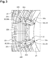
- the electric drive unit 18 furthermore comprises a stator 22 and a rotor 24, depicted merely schematically in figure 2 and figure 3 , which is rotatable about a rotor axis 26.
- stator 22 is arranged in an annular stator chamber 22a of a drive housing 28, and the rotor 24 is arranged in a rotor chamber 24a which is separate from the stator chamber 22a and lies inside this.
- the rotor chamber 24a thus lies in the interior of the ring shape.
- the rotor 24 is thus a so-called internal rotor.
- stator 22 is encapsulated inside the stator chamber 22a by means of a casting compound 23.
- stator 22 is embedded in the stator chamber 22a by means of the casting compound 23.
- Both the rotor chamber 24a and the stator chamber 22a are formed pot-like, wherein the stator chamber 22a and the rotor chamber 24a are open on opposite axial sides.
- This so-called double pot form is configured as part of the drive housing.
- the stator 22 comprises several stator segments 22b which are distributed around its circumference. Of the total of twelve stator segments 22b present in the embodiment according to figure 2 , for reasons of clarity only a few are marked with a reference sign.
- a radial depression 22c is provided between respective adjacent stator segments 22b.
- the rotor chamber 24a and the stator chamber 22a are separated by an inner wall 30.
- This inner wall 30 thus delimits the stator chamber 22a radially inwardly and the rotor chamber 24a radially outwardly.
- the radial bulges 30b and radial recesses 30c extend substantially over the entire axial length of the inner wall 30.
- Each of the radial bulges 30b here engages in a respective assigned radial depression 22c of the stator 22, so that the stator 22 is mounted non-rotatably in the drive housing 28.
- the radial bulges 30b and the radial depressions 22c create a form-fit connection acting in the circumferential direction.
- a coolant channel 30d running substantially axially is formed in each wall portion 30a and is radially open in the direction of the rotor chamber 24a. Via the coolant channels 30d, coolant can be conducted into the rotor chamber 24a so that the electrical drive unit 18 is cooled. This applies in particular to the rotor 24.
- the wall portions 30a are rounded at their radial outsides.
- the radial outsides of the wall portions 30a thus take the form of part circles.
- the axially running coolant channels 30d may firstly be equipped with a comparatively large flow cross-section.
- the cooling channels 30d have a comparatively large surface area because of the rounded form of the wall portions 30a, so that a heat exchange between the coolant flowing in the cooling channels 30d and the stator chamber 22 is promoted.
- the fluid pump 10 may be produced as follows.
- stator 22 with the circumferentially distributed stator segments 22b and the radial depressions 22c lying in between is produced.
- the drive housing 28 is produced in which the stator chamber 22a is present.
- stator chamber 22a is delimited radially inwardly by the inner wall 30, and the inner wall 30 has wall portions which protrude relative to a base contour. These wall portions 30a are designed as radial bulges 30a on the stator side.
- stator 22 is aligned relative to the drive housing 28 so that each of the radial depressions 22c along the rotor axis 26 lies opposite a corresponding wall portion 30a, i.e. a corresponding radial bulge 30b.
- stator is inserted into the drive housing 28 along the rotor axis 26, wherein the protruding wall portions 30a in the form of radial bulges 30b engage in the assigned radial depressions 22c.
- stator 22 is encapsulated in the stator chamber 22a by means of a casting compound 23.
Landscapes
- Engineering & Computer Science (AREA)
- Power Engineering (AREA)
- Mechanical Engineering (AREA)
- General Engineering & Computer Science (AREA)
- Manufacturing & Machinery (AREA)
- Details And Applications Of Rotary Liquid Pumps (AREA)
- Rotary Pumps (AREA)
- Microelectronics & Electronic Packaging (AREA)
Applications Claiming Priority (1)
| Application Number | Priority Date | Filing Date | Title |
|---|---|---|---|
| DE102019130717.1A DE102019130717A1 (de) | 2019-11-14 | 2019-11-14 | Flüssigkeitspumpe |
Publications (1)
| Publication Number | Publication Date |
|---|---|
| EP3823135A1 true EP3823135A1 (de) | 2021-05-19 |
Family
ID=73172481
Family Applications (1)
| Application Number | Title | Priority Date | Filing Date |
|---|---|---|---|
| EP20206090.1A Withdrawn EP3823135A1 (de) | 2019-11-14 | 2020-11-06 | Flüssigkeitspumpe |
Country Status (5)
| Country | Link |
|---|---|
| US (1) | US20210148357A1 (de) |
| EP (1) | EP3823135A1 (de) |
| KR (1) | KR20210058708A (de) |
| CN (1) | CN112796994A (de) |
| DE (1) | DE102019130717A1 (de) |
Citations (7)
| Publication number | Priority date | Publication date | Assignee | Title |
|---|---|---|---|---|
| JPS59226634A (ja) * | 1983-06-03 | 1984-12-19 | Nikkiso Co Ltd | キャンドモータポンプ |
| US5015159A (en) * | 1989-06-01 | 1991-05-14 | Aisan Kogyo Kabushiki Kaisha | Fuel pump |
| US20090022610A1 (en) * | 2006-02-23 | 2009-01-22 | Thomas Materne | Motor centrifugal pump |
| JP5902061B2 (ja) * | 2012-07-26 | 2016-04-13 | 愛三工業株式会社 | 燃料ポンプ |
| EP3179106A1 (de) | 2015-12-09 | 2017-06-14 | FTE automotive GmbH | Elektromotorisch angetriebene flüssigkeitspumpe |
| US20170343006A1 (en) * | 2016-05-30 | 2017-11-30 | Bühler Motor GmbH | Electric centrifugal pump with containment shell grooves |
| US10153677B2 (en) * | 2015-01-20 | 2018-12-11 | Aisan Kogyo Kabushiki Kaisha | Stator and electric pump |
Family Cites Families (11)
| Publication number | Priority date | Publication date | Assignee | Title |
|---|---|---|---|---|
| US2428236A (en) * | 1943-05-28 | 1947-09-30 | Gen Electric | Dynamoelectric machine |
| GB1330674A (en) * | 1970-09-24 | 1973-09-19 | Siemens Ag | Electrical motor |
| DE3931665C1 (en) * | 1989-09-22 | 1991-02-21 | Wilo-Werk Gmbh & Co Pumpen- Und Apparatebau, 4600 Dortmund, De | Split-ring electric motor for pump - has feeder coupled to pump chamber at point exhibiting high pressure |
| DE10226976A1 (de) * | 2002-06-17 | 2004-03-25 | Siemens Ag | Elektromotor mit einem mehrpoligen Rotor und einem mehrpoligen Stator |
| EP2246962B1 (de) * | 2009-04-30 | 2020-07-29 | General Electric Company | Hochgeschwindigkeitsmaschine mit internem Permanentmagnet |
| TWI594551B (zh) * | 2012-03-29 | 2017-08-01 | 荏原製作所股份有限公司 | 密封電動機、真空泵 |
| DE102012215232A1 (de) * | 2012-08-28 | 2014-03-06 | Robert Bosch Gmbh | Stator in einem Elektromotor |
| DE102013211573A1 (de) * | 2013-06-19 | 2014-12-24 | BSH Bosch und Siemens Hausgeräte GmbH | Pumpe mit einer Verdrehsicherung und Haushaltsgerät mit einer solchen Pumpe |
| JP2019030111A (ja) * | 2017-07-28 | 2019-02-21 | 日本電産株式会社 | ステータ、モータ、送風装置、及びステータの製造方法 |
| DE102018102750A1 (de) * | 2018-02-07 | 2019-08-08 | IPGATE Capital Holding AG | Stator für Drehfeldmaschine mit axialer Wärmeableitung |
| CN110247531A (zh) * | 2018-03-07 | 2019-09-17 | 广东美的生活电器制造有限公司 | 食品料理机和用于食品料理机的电机 |
-
2019
- 2019-11-14 DE DE102019130717.1A patent/DE102019130717A1/de active Pending
-
2020
- 2020-11-04 US US17/089,167 patent/US20210148357A1/en not_active Abandoned
- 2020-11-06 EP EP20206090.1A patent/EP3823135A1/de not_active Withdrawn
- 2020-11-11 KR KR1020200150277A patent/KR20210058708A/ko not_active Withdrawn
- 2020-11-13 CN CN202011275349.8A patent/CN112796994A/zh active Pending
Patent Citations (7)
| Publication number | Priority date | Publication date | Assignee | Title |
|---|---|---|---|---|
| JPS59226634A (ja) * | 1983-06-03 | 1984-12-19 | Nikkiso Co Ltd | キャンドモータポンプ |
| US5015159A (en) * | 1989-06-01 | 1991-05-14 | Aisan Kogyo Kabushiki Kaisha | Fuel pump |
| US20090022610A1 (en) * | 2006-02-23 | 2009-01-22 | Thomas Materne | Motor centrifugal pump |
| JP5902061B2 (ja) * | 2012-07-26 | 2016-04-13 | 愛三工業株式会社 | 燃料ポンプ |
| US10153677B2 (en) * | 2015-01-20 | 2018-12-11 | Aisan Kogyo Kabushiki Kaisha | Stator and electric pump |
| EP3179106A1 (de) | 2015-12-09 | 2017-06-14 | FTE automotive GmbH | Elektromotorisch angetriebene flüssigkeitspumpe |
| US20170343006A1 (en) * | 2016-05-30 | 2017-11-30 | Bühler Motor GmbH | Electric centrifugal pump with containment shell grooves |
Also Published As
| Publication number | Publication date |
|---|---|
| US20210148357A1 (en) | 2021-05-20 |
| CN112796994A (zh) | 2021-05-14 |
| KR20210058708A (ko) | 2021-05-24 |
| DE102019130717A1 (de) | 2021-05-20 |
Similar Documents
| Publication | Publication Date | Title |
|---|---|---|
| JP6873677B2 (ja) | 電動モータで駆動される液体ポンプ | |
| EP2395631B1 (de) | Elektromotor und rotor | |
| US9660506B2 (en) | Electric motor having a communication passage | |
| EP1302704B1 (de) | Eingetauchte, elektrische Fluidpumpe | |
| US20120164009A1 (en) | Electric pump unit | |
| US12206293B2 (en) | Liquid-cooled rotor for an electromechanical energy converter | |
| US9698650B2 (en) | Electric device, gearbox and associated method | |
| US20130214624A1 (en) | Electric machine cooling | |
| RU2542744C2 (ru) | Электрическая машина для гибридных или электрических транспортных средств | |
| US20140097711A1 (en) | One piece rotor hub/shaft for an electric machine and method | |
| US20180115219A1 (en) | Cooling structure of drive motor | |
| CN109690918B (zh) | 具有冷却套的电驱动单元 | |
| JP2018038099A (ja) | 電動モータ | |
| EP2034187B1 (de) | Spiralverdichter | |
| WO2020176572A1 (en) | Electric machine with internal cooling passageways | |
| EP3823135A1 (de) | Flüssigkeitspumpe | |
| JP2007321570A (ja) | 燃料ポンプ | |
| CN100400892C (zh) | 电驱动的泵 | |
| JP7233966B2 (ja) | 回転電機 | |
| JP6475041B2 (ja) | 滑り軸受及び電動流体ポンプ | |
| JP2014108030A (ja) | 電動モータ及びファンモータ | |
| KR20160006707A (ko) | 펌프 장치 | |
| CN210118286U (zh) | 泵壳结构、泵体和车辆 | |
| CN220273446U (zh) | 电机和驱动单元 | |
| EP4428370A1 (de) | Zahnradpumpe |
Legal Events
| Date | Code | Title | Description |
|---|---|---|---|
| PUAI | Public reference made under article 153(3) epc to a published international application that has entered the european phase |
Free format text: ORIGINAL CODE: 0009012 |
|
| STAA | Information on the status of an ep patent application or granted ep patent |
Free format text: STATUS: REQUEST FOR EXAMINATION WAS MADE |
|
| 17P | Request for examination filed |
Effective date: 20201106 |
|
| AK | Designated contracting states |
Kind code of ref document: A1 Designated state(s): AL AT BE BG CH CY CZ DE DK EE ES FI FR GB GR HR HU IE IS IT LI LT LU LV MC MK MT NL NO PL PT RO RS SE SI SK SM TR |
|
| P01 | Opt-out of the competence of the unified patent court (upc) registered |
Effective date: 20230629 |
|
| STAA | Information on the status of an ep patent application or granted ep patent |
Free format text: STATUS: EXAMINATION IS IN PROGRESS |
|
| 17Q | First examination report despatched |
Effective date: 20231218 |
|
| STAA | Information on the status of an ep patent application or granted ep patent |
Free format text: STATUS: THE APPLICATION HAS BEEN WITHDRAWN |
|
| 18W | Application withdrawn |
Effective date: 20240319 |