EP3823729B1 - Lösbare schubvorrichtung zum öffnen einer tür - Google Patents
Lösbare schubvorrichtung zum öffnen einer tür Download PDFInfo
- Publication number
- EP3823729B1 EP3823729B1 EP19790620.9A EP19790620A EP3823729B1 EP 3823729 B1 EP3823729 B1 EP 3823729B1 EP 19790620 A EP19790620 A EP 19790620A EP 3823729 B1 EP3823729 B1 EP 3823729B1
- Authority
- EP
- European Patent Office
- Prior art keywords
- support bar
- rod
- jack
- upper support
- fixed
- Prior art date
- Legal status (The legal status is an assumption and is not a legal conclusion. Google has not performed a legal analysis and makes no representation as to the accuracy of the status listed.)
- Active
Links
Images


Classifications
-
- A—HUMAN NECESSITIES
- A62—LIFE-SAVING; FIRE-FIGHTING
- A62B—DEVICES, APPARATUS OR METHODS FOR LIFE-SAVING
- A62B3/00—Devices or single parts for facilitating escape from buildings or the like, e.g. protection shields, protection screens; Portable devices for preventing smoke penetrating into distinct parts of buildings
- A62B3/005—Rescue tools with forcing action
Definitions
- the present invention relates to a removable thrust device for the opening by pushing of a door, capable of exerting a thrust on the vertical surface of the door and its pushing.
- the present invention also relates to a method for exerting a thrust preferably of at least 50 kN on a door or any other vertical flat surface from external support points.
- the invention relates to a device for opening, as quickly as possible from a set of at least 3 parts ready to be assembled, by force, without shock and in silence, any type of door for a home, industrial premises or other.
- a device for exerting a thrust on the vertical surface of a door to effect the opening by pushing said door is perfectly adapted for the opening of doors opening by pushing or pulling, from the face of said door where the thrust or pull on said door must be exerted to open it.
- These devices operate by pushing on the door thanks to supports at three levels, namely on the ground, on the central part of the door panel, where the door is pushed, and on the upper part or lintels of the door retaining and stop frame, where the direct thrust by a jack is exerted.
- the articulation of the end of the movable rod of said jack on said intermediate sole plate allows it to be arranged at an inclination preferably of 20 to 35° relative to the vertical, so as to be able to exert a thrust preferably of at least 50 kN on said intermediate sole plate when said intermediate sole plate is applied in support on said door or vertical flat surface and said jack is in support on a lower external support point, preferably on the ground.
- the articulation of said upper support bar on said intermediate sole plate makes it possible to arrange said bar substantially vertically so as to be able to apply its free end directly in support on an upper external support point preferably constituted by the frame of said door or a ceiling, or a horizontal flat surface located above said vertical flat surface.
- the term "free end” means the end of said bar which is not fixed to said intermediate sole plate.
- the device of FR 2 825 354 is perfectly suited for opening doors that open by pushing on the side where the push device is located on the door, i.e. so-called doors “push” doors opening towards the inside of the room from the outside of which it is sought to be opened.
- the device works on push doors thanks to its supports at three levels, namely: on the ground, on the door and, on the upper part or lintel of the retaining and stop frame of the door.
- the upper end of the upper support bar abuts below and against the part of the lintel of the door frame projecting from the vertical plane of the door surface and against which the upper end of the door abuts.
- This part of the lintel located lower than the upper end of the door in fact ensures that the door is held in its frame when the door is closed by pulling it.
- FR 2 944 709 provides a pushing device on a door with a vertical flat surface adapted for a pulling door, that is to say that one seeks to open from the outside, the retaining belt of the door frame being located on the inside.
- This device for opening by pushing a door capable of exerting a push on the vertical surface of the door and its pushing, when the device is positioned against the door on the side where it opens by pulling it, comprises an upper support device fixed in an articulated manner, preferably in a removable manner, to the upper end of said upper support bar, said upper support device comprising at least one wedging and blocking part capable of allowing the rotational articulation of said wedging and blocking part relative to the upper end of said upper support bar.
- Said wedging and blocking device thus fulfils the same technical effect as the part of the lintel projecting from the vertical plane of the door serving as a stop, in a door opening device without this blocking and wedging device at the upper end of the upper support bar, when the door opening device is located on the side where the door opens by pushing.
- the jack is intended to rest on the ground, but could also rest on a lower external support point.
- the intermediate sole is intended to rest on the door, but could rest on a median external support point.
- articulatedly means that the two parts fixed to each other can pivot relative to each other at least around a horizontal axis when the longitudinal directions of said lower support bar and upper support bar are located in the same vertical plane.
- thrust devices are known from GB 2 236 803 A , WO 2010/125263 A1 And FR 2 983 736 A1 .
- the devices described in these known documents are not optimally suited for easy transport and implementation, in particular because the upper support bar and lower support bar are each in one piece and therefore of a relatively long length.
- the device In its current configuration, the device is bulky, complicated to carry, particularly during interventions on the upper floors of a building, leading to risks of impact on the walls and the stairwell railings, and not easy to put in place on the door or remove after implementation.
- This bulkiness also affects its packaging and transport for carrying over long distances, because currently the device can only be separated into two very long elements comprising (a) the lower support bar with the jack and the lower sole and (b) the upper support bar with the intermediate sole and the upper support device.
- the aim of the present invention is to provide a device that overcomes these drawbacks.
- the present invention provides a door opening device that can be dismantled into at least 3 parts. manually and without any tools, which allows easier carrying because it can be shared between several people if necessary, and without the risk of shock in stairwells when carrying up and down the floors of a building, and finally it can be assembled in a few seconds on the door concerned. It can also be packaged in a much smaller carrying case than the one currently used, which can be carried by a single person.
- the present invention provides a door opening push device that can be mounted from a ready-to-assemble assembly of at least 3 parts by reversible fixing devices that can be activated and deactivated manually, and capable of maintaining in rectilinear alignment lower and upper parts of the lower and upper support bars.
- the present invention provides a pushing device for exerting a push on a door or any other vertical flat surface such as a partition, comprising a lower support bar, an intermediate support sole and an upper support bar, and preferably a lower support sole, each of said lower support bar and respectively upper support bar being capable of being actuated in telescopic extension in which the pushing device is capable of being assembled from a ready-to-assemble assembly of at least 3 parts comprising two reversible fixing devices which can be activated and deactivated manually, capable of carrying out the reversible fixing of the lower and upper parts of each of said lower support bar and respectively upper support bar and capable of maintaining said lower support bar and upper support bar in rectilinear alignment when they are actuated in said telescopic extension.
- varying the distance between said lower part and upper part of the upper support bar means that it is a question of varying the ends of said lower part and upper part of the upper support bar fixed or capable of being fixed on said intermediate sole and respectively said upper support sole, and by "fixed in an articulated manner in rotation on said sole fixed in an articulated manner in rotation on and relative to said sole..”, that it is a articulation in rotation relative to said sole concerned.
- said first fixing device comprises an upper end portion of said first cylinder rod capable of cooperating and being reversibly fixed to a complementary lower end portion of said upper portion of the lower support bar.
- said first fixing device comprises a said upper end portion of said first cylinder rod of male shape, preferably outside said cylinder body when said first cylinder rod is in the retracted position, capable of engaging and being fixed reversibly in a said complementary lower end portion of female shape such as a first cavity of said upper portion of the lower support bar.
- said upper terminal part of the first cylinder rod and said first cavity are of shapes complementary cylindrical rods capable of fitting into each other to activate said first fixing device and deactivate it under manual control, and of the same length d1 sufficient to maintain said rectilinear alignment, preferably of smaller diameter than that of said first cylinder rod.
- said first fixing device comprises an upper end portion of said first cylinder rod in the form of a cavity capable of receiving and being reversibly fixed to a said lower end portion of complementary male shape of said upper portion of the lower support bar.
- said first cylinder rod comprises two telescopic elements. It is understood that said upper end portion of the first cylinder rod is at the end of the rod element furthest from the cylinder body when the cylinder rod is extended.
- This embodiment is advantageous because it allows the cylinder body to be of shorter length while being able to receive the cylinder rod retracted inside the cylinder body and offers safety with regard to the risk of buckling of the cylinder rod when the thrust device is implemented.
- said second fixing device comprises an upper end portion of said second rod capable of cooperating and being reversibly fixed to a complementary lower end portion of said upper portion of the upper support bar.
- said second fixing device comprises a said upper terminal part of said second rod, preferably of smaller diameter than that of said second rod, capable of engaging and being fixed reversibly in a second cavity at the lower end of said upper portion of the upper support bar.
- said upper terminal part of the second rod and said second cavity are of complementary cylindrical shape capable of entering into one another to activate said second fixing device and deactivate it under manual control and of the same length d2 sufficient to maintain said rectilinear alignment.
- said second fixing device comprises a said upper end portion of said second rod in the form of a cavity capable of receiving and being reversibly fixed to a complementary male end portion at the lower end of said upper portion of the upper support bar.
- said second rod comprises a thread which is capable of cooperating with a peripheral wheel crossed by said second rod such that the manual rotation of said wheel causes said relative sliding of said second rod relative to said lower part of the upper support bar.
- said upper support device is fixed in an articulated manner, preferably removably, to the upper end of said upper support bar, said upper support device comprising at least one wedging and blocking part capable of allowing the opening of a pull door.
- At least one of said lower sole and intermediate sole comprises a flat support, one face of which is intended to come to bear on the ground or respectively said door or vertical flat surface, comprising non-slip elements, preferably hard points, and the other face of which comprises articulation means on which articulated fixing means are fixed.
- the pushing device thus dismantled is suitable for storage in a small suitcase.
- a thrust is exerted on an armoured door to force it open by exerting a thrust on said intermediate sole until an increase in the inclination of said jack is obtained by an angle of at least 3°, preferably an increase of 5 to 20°.
- the thrust device according to the invention 1 is shown assembled and applied to the door ready to exert a thrust with said first rod still in the retracted position and said second rod 7c in the extended position to block the upper support device 7a1 at the upper end of the upper support bar 7 against the lintel 2a of the door ( Figure 3A ), and in the process of pushing with the said first rod 4-2 in the extension position and the second rod 7c in the extension position ( Figure 3B ).
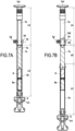
- FIG. 5A shows the detail of the first fixing device.
- the cylinder 4 being in the retracted position with only the terminal part 4-2c of smaller diameter than the second cylinder rod element 4-2b protruding outside the cylinder body 4-1.
- the terminal part 4-2c is of diameter and length d1 substantially identical to those of the first cylindrical cavity 4b1 at the lower end of the upper part 4b of the lower support bar.
- the thrust device according to the invention is shown with said second rod 7c in the position of maximum extension with its upper terminal part 7d of length d2 of smaller diameter than the second rod 7c.
- the thread of the second rod 7c and an annular knurl 7e rotatable relative to the longitudinal axis XX' of the upper support bar 7 are shown, arranged at the upper end of the tubular wall of the lower part 7b of the upper support bar 7 to form with the second threaded rod 7c a ball screw system.
- the thread of the second rod 7c cooperates with the knurl 7e so that a manual control of rotation of the knurl 7e causes a sliding in longitudinal translation along the axis XX' of the second rod in part 7c1 inside the tubular wall 7b and through the knurl 7e to extend in part 7c2 over a length d3 outside the lower tubular part 7b.
- the second rod 7c is in the maximum retracted position with only the upper end portion 7d protruding from the lower tubular portion 7b of the upper support bar.
- the lower part 7b of another embodiment of the upper support bar 7 is shown with a said upper end part 7d in the form of a cavity and the second rod 7c in the retracted position inside the tubular wall of the lower part 7b of the upper support bar 7.
- the sliding of the second rod 7c being able to be controlled by an electric motor 8 powered by a battery 8a arranged inside the tubular wall of the lower part 7b of the upper support bar 7.
- the motor 8 is arranged below the second rod 7c with which the motor 8 is able to cooperate so as to be able to rotate the screw which constitutes the second rod 7c causing its relative translation in sliding relative to the wheel 7e with which it cooperates.
- FIG. 7A and 7B another embodiment of the second reversible fixing device 7h', 7g' is shown between (1) the lower end portion 7a2 of the upper portion 7a of said other embodiment of the upper support bar 7 and (2) the upper end portion 7d in the form of a cavity of the second rod 7c.
- the lower end portion 7a2 comprises a hollow annular groove 7g' capable of receiving the end of a locking finger 7h'.
- the finger 7h' cooperates with an elastic means in an opening in the tubular wall of the cavity 7d so that the finger engages in the groove 7g' when the end portion 7a2 is fully engaged in the cavity 7d. And, by pulling on the finger 7h' it can be removed from the groove 7g' which allows the end portion 7a2 to be removed from the cavity 7d.
Landscapes
- Health & Medical Sciences (AREA)
- General Health & Medical Sciences (AREA)
- Business, Economics & Management (AREA)
- Emergency Management (AREA)
- Conveying And Assembling Of Building Elements In Situ (AREA)
- Wing Frames And Configurations (AREA)
Claims (13)
- Vorrichtung (1), die zum Ausüben eines Schubes auf eine Tür (2) oder jede andere vertikale ebene Fläche (3) wie eine Trennwand imstande ist, umfassend eine untere Stützstange (4), eine mittlere Stützsohle (6) und eine oberen Stützstange (7), wobei jeweils jede von der unteren Stützstange (4) und der oberen Stützstange (7) geeignet ist, teleskopisch ausgefahren zu werden, wobei die Vorrichtung (1) in mindestens drei Teile (1-1, 1-2, 1-3) demontierbar ist und eine erste reversible Befestigungsvorrichtung (4c-4d) und eine zweite reversible Befestigungsvorrichtung (7g-7h) umfasst, die manuell aktivierbar und deaktivierbar sind, wobei die Befestigungsvorrichtungen geeignet sind, die reversible Befestigung der unteren (4a, 7b) und oberen (4b, 7a) Teile jeder von der jeweils unteren Stützstange (4) und oberen Stützstange (7) durchzuführen und imstande sind, die untere Stützstange (4) und die obere Stützstange (7) in geradliniger Ausrichtung zu halten, wenn sie teleskopisch ausgefahren sind, wobei- die untere Stützstange (4) einen unteren Teil umfasst, der einen Zylinder (4a) umfasst, wobei der Zylinder einen Zylinderkörper (4-1) umfasst, dessen unteres Ende vorzugsweise drehgelenkig (4r1) an einer unteren Stützsohle (5) befestigt ist oder imstande ist, befestigt zu sein, und eine erste Zylinderstange (4-2), und wobei ein oberer Teil (4b) der unteren Stützstange (4) drehgelenkig (4r2) an der mittleren Sohle (6) befestigt ist oder imstande ist, befestigt zu sein,- die obere Stützstange (7) einen unteren Teil (7b) umfasst, der drehgelenkig (7r1) an und in Bezug auf die mittlere Sohle (6) befestigt ist oder imstande ist, befestigt zu sein, und einen oberen Teil (7a) der oberen Stützstange (7), der eine obere Stützvorrichtung (7a1) umfasst, wobei die obere Stützstange (7) teleskopisch ausfahrbar ist, um den Abstand zwischen dem unteren Teil (7b) und dem oberen Teil (7a) der oberen Stützstange (7) zu variieren,- die erste Zylinderstange (4-2) über die erste reversible Befestigungsvorrichtung (4-2c, 4b1, 4c-4d) am oberen Teil (4b) der unteren Stützstange (4) befestigt ist oder imstande ist, reversibel befestigt zu sein, wobei die teleskopische Betätigung der ersten Zylinderstange (4-2) imstande ist, den Abstand zwischen dem Zylinderkörper (4a1) und dem oberen Teil (4b) der unteren Stützstange (4) zu variieren, wobei die erste reversible Befestigungsvorrichtung (4-2c, 4b1, 4c-4d), wenn sie aktiviert ist, imstande ist, den oberen Teil (4b) der unteren Stützstange (4) in geradliniger Ausrichtung mit der ersten Zylinderstange (4-2) zu halten, an der sie bei der teleskopischen Betätigung der ersten Zylinderstange befestigt ist,- die obere Stützstange (7) eine zweite Stange (7c) umfasst oder mit dieser zusammenwirkt, die sich zumindest teilweise im Inneren (7c1) der oberen Stützstange (7) erstreckt, wobei die zweite Stange (7c) manuell oder elektrisch in die teleskopisch ausfahrbar ist, um den Abstand zwischen dem unteren Teil (7a) und dem oberen Teil (7b) der oberen Stützstange (7) zu variieren, wobei die zweite Stange (7c) über die zweite reversible Befestigungsvorrichtung (7a2, 7d, 7g, 7h) am oberen Teil (7a) der oberen Stützstange (7) reversibel befestigt ist oder imstande ist, befestigt zu sein, wobei die zweite Befestigungsvorrichtung (7a2, 7d, 7g, 7h), wenn sie aktiviert ist, imstande ist, den unteren Teil (7a) und den oberen Teil (7b) der oberen Stützstange (7), die aneinander in geradliniger Ausrichtung zueinander befestigt sind, zu halten, wenn die zweite Stange (7c) teleskopisch betätigt wird.
- Vorrichtung nach Anspruch 1, dadurch gekennzeichnet, dass die erste Befestigungsvorrichtung einen oberen terminalen Teil (4-2c) der ersten Zylinderstange (4a2) umfasst, der imstande ist, mit einem komplementären unteren terminalen Teil (4b1) des oberen Abschnitts (4b) der unteren Stützstange (4) zusammenzuwirken und reversibel daran befestigt zu sein.
- Schubvorrichtung nach Anspruch 2, dadurch gekennzeichnet, dass die erste Befestigungsvorrichtung einen oberen terminalen Teil (4-2c) der männlich geformten ersten Zylinderstange (4a2) umfasst, vorzugsweise außerhalb des Zylinderkörpers, wenn die erste Zylinderstange in der eingefahrenen Position ist, die imstande ist, in einen komplementären weiblich geformten unteren terminalen Teil (4b1) wie ein erster Hohlraum (4b1) des oberen Teils (4b) der unteren Stützstange (4) einzugreifen und reversibel befestigt zu sein.
- Vorrichtung nach Anspruch 3, dadurch gekennzeichnet, dass der obere terminale Teil (4-2c) der ersten Zylinderstange (4-2) und der erste Hohlraum (4b1) komplementäre zylindrische Formen haben, die imstande sind, ineinander zu passen, um die erste Befestigungsvorrichtung zu aktivieren und sie unter manueller Steuerung zu deaktivieren, und gleicher Länge d1, die ausreicht, um die geradlinige Ausrichtung zu halten, vorzugsweise mit einem kleineren Durchmesser als die erste Zylinderstange.
- Vorrichtung nach einem der Ansprüche 1 bis 4, dadurch gekennzeichnet, dass die erste Zylinderstange zwei teleskopische Elemente (4-2a, 4-2b) umfasst.
- Vorrichtung nach einem der Ansprüche 1 bis 5, dadurch gekennzeichnet, dass die zweite Befestigungsvorrichtung (7a2, 7d, 7g, 7h) einen oberen terminalen Teil (7d) der zweiten Stange (7c) umfasst, der imstande ist, mit einem komplementären unteren terminalen Teil (7a2) des oberen Teils (7a) der oberen Stützstange (7) zusammenzuwirken und reversibel befestigt zu sein.
- Vorrichtung nach Anspruch 6, dadurch gekennzeichnet, dass die zweite Befestigungsvorrichtung (7d-7g-7h) einen oberen terminalen Teil (7d) der zweiten Stange (7c) umfasst, vorzugsweise mit einem kleineren Durchmesser als die zweite Stange (7c), der imstande ist, in einen zweiten Hohlraum (7a2) am unteren Ende des oberen Teils (7a) der oberen Stützstange (7) einzugreifen und reversibel befestigt zu sein.
- Vorrichtung nach Anspruch 7, dadurch gekennzeichnet, dass der obere terminale Teil (7d) der zweiten Stange (7c) und der zweite Hohlraum (7b1) komplementäre zylindrische Formen haben, die imstande sind, ineinander zu passen, um die zweite Befestigungsvorrichtung zu aktivieren und sie unter manueller Steuerung zu deaktivieren, und gleicher Länge d2, die ausreicht, um die geradlinige Ausrichtung zu halten.
- Vorrichtung nach einem der Ansprüche 1 bis 8, dadurch gekennzeichnet, dass die zweite Stange (7c) ein Gewinde (7c1) umfasst, das imstande ist, mit einem peripheren Rändelrad (7e) zusammenzuwirken, das von der zweiten Stange durchquert wird, so dass die manuelle Drehung des Rändelrads die relative Verschiebung der zweiten Stange (7c) in Bezug auf den unteren Teil (7b) der oberen Stützstange (7) bewirkt.
- Vorrichtung nach einem der Ansprüche 3 und 7, dadurch gekennzeichnet, dass mindestens eine von der ersten oder zweiten Befestigungsvorrichtung umfasst:a) einen ersten oder beziehungsweise zweiten transversalen Verriegelungsfinger (4c1, 7g1), der imstande ist, mit einer ersten oder beziehungsweise zweiten Feder (4c2, 7g2) am Boden einer ersten oder beziehungsweise zweiten hohlen Aufnahme (4c3, 7g3) im Bereich des oberen terminalen Teils (4-2c, 7d) der ersten oder beziehungsweise zweiten Stange (4-2, 7c) zusammenzuwirken, wobei der erste oder beziehungsweise zweite Verriegelungsfinger (4c1, 7g1) imstande ist, durch Kompression der ersten oder beziehungsweise zweiten Feder (4c2, 7g2) eingezogen zu werden, wenn die erste oder beziehungsweise zweite Stange (4-2, 7c) beginnt, in den ersten oder beziehungsweise zweiten Hohlraum einzutreten, und wobei der erste oder beziehungsweise zweite Verriegelungsfinger (4c1, 7g1) imstande ist, in eine erste oder beziehungsweise zweite Öffnung (4d2, 7h2) im Bereich der röhrenförmigen Wand des ersten oder beziehungsweise zweiten Hohlraums einzutreten, durch Ausdehnen der ersten oder beziehungsweise zweiten Feder (4c2, 7g2), wenn der terminale Teil (4-2c, 7d) der ersten oder beziehungsweise zweiten Stange (4-2, 7c) vollständig in den ersten oder beziehungsweise zweiten Hohlraum eingetreten ist, um die erste oder beziehungsweise zweite reversible Befestigungsvorrichtung zu aktivieren,b) einen ersten oder beziehungsweise zweiten Entriegelungsdruckknopf (4d1, 7h1), der innerhalb der ersten oder beziehungsweise zweiten Öffnung (4d2, 7h2) im Bereich der röhrenförmigen Wand des ersten oder beziehungsweise zweiten Hohlraums angeordnet ist, wobei der erste oder beziehungsweise zweite Entriegelungsdruckknopf (4d1, 7h1) imstande ist, manuell betätigt zu werden, um den ersten oder beziehungsweise zweiten transversalen Verriegelungsfinger (4c1, 7g1) durch Kompression der ersten oder beziehungsweise zweiten Feder (4c2, 7g2) am Boden der ersten oder beziehungsweise zweiten hohlen Aufnahme (4c3, 7g3) einzudrücken und einzuziehen, um die erste oder beziehungsweise zweite reversible Befestigungsvorrichtung zu deaktivieren.
- Zusammenbaufertige Anordnung zur Bildung einer Schubvorrichtung nach einem der Ansprüche 1 bis 10, umfassend mindestens drei unabhängige Teilen (1-1, 1-2, 1-3) vorzugsweise mit im Wesentlichen der gleichen Länge, umfassend:(1) einen ersten Teil (1-1), der den unteren Teil (4a) der unteren Stützstange umfasst, der den Zylinder umfasst, dessen Zylinderkörper (4-1) vorzugsweise drehgelenkig (4r1) an der unteren Stützsohle (5) befestigt ist oder imstande ist, befestigt zu sein, wobei die erste Zylinderstange (4-2) in einer eingezogenen Position innerhalb des Zylinderkörpers ist,(2) einen zweiten Teil (1-2), der umfasst:(a) den oberen Teil (4b) der unteren Stützstange (4), der drehgelenkig (4r2) an der mittleren Sohle (6) befestigt ist, und(b) den unteren Teil (7b) der oberen Stützstange (7), der drehgelenkig (7r1) an der mittleren Sohle (6) befestigt ist, wobei die zweite Stange (7c) zumindest teilweise in das Innere (7c1) eines röhrenförmigen Endes des unteren Teils (7b) der oberen Stützstange (7) eingezogen ist, und(c) der obere Teil (4b) der unteren Stützstange (4) und der untere Teil (7b) der oberen Stützstange (7) in Bezug auf die mittlere Sohle derart gedreht werden, dass sie im Wesentlichen parallel gegeneinander oder gegenüberliegend angeordnet sind, und(3) einen dritten Teil (1-3), der den oberen Teil (7a) der oberen Stützstange (7) umfasst, der vorzugsweise eine obere Stützvorrichtung (7a1) umfasst.
- Verfahren zum Ausüben eines Schubes von vorzugsweise mindestens 50 kN auf eine Tür oder auf jede andere vertikale ebene Fläche (2, 3) ausgehend von äußeren Stützpunkten (8, 2a), wobei eine Schubvorrichtung nach einem der Ansprüche 1 bis 10 verwendet wird, dadurch gekennzeichnet, dass die Schritte durchgeführt werden, bei denen:a) die untere Stützstange (4) mit dem Zylinder (4a) in eingezogener Position angeordnet wird, in Schräglage von vorzugsweise 20 bis 35° zur Vertikalen, mit- der mittleren Sohle (6) in Anlage an der Tür oder der vertikalen ebenen Fläche (2, 3),- wobei der Zylinder (4a) in der eingefahrenen Position auf einem unteren äußeren Stützpunkt, vorzugsweise dem Boden (8), anliegt, vorzugsweise über eine untere Sohle (5),- wobei die obere Stützstange (7) teleskopisch ausgefahren wird, um an einem oberen äußeren Stützpunkt anzuliegen, vorzugsweise einem Sturz (2a) des Rahmens einer Tür (2) oder einer Decke oder einer horizontalen ebenen Fläche, die sich über der vertikalen ebenen Fläche befindet, undb) die erste bewegliche Stange (4-2) des Zylinders ausgefahren wird, um einen Schub auf die mittlere Sohle (6) auszuüben.
- Verfahren nach Anspruch 12, dadurch gekennzeichnet, dass die folgenden Schritte durchgeführt werden, bei denen:- vor Schritt a) die Montage zwischen dem unteren Teil (4a) und dem oberen Teil (4b) der unteren Stützstange (4) und zwischen dem unteren Teil (7b) und dem oberen Teil (7a) der oberen Stützstange (7) durchgeführt wird, indem die erste und die zweite Befestigungsvorrichtung manuell aktiviert werden, bevor die untere Stützstange (4) oder beziehungsweise die obere Stützstange (7) in Position gegen die Tür gebracht werden, und- nach Schritt b) die erste und zweite Befestigungsvorrichtung manuell deaktiviert werden, um jeweils den unteren Teil (4a) der unteren Stützstange und den oberen Teil (7b) der oberen Stützstange getrennt zu lagern.
Applications Claiming Priority (2)
| Application Number | Priority Date | Filing Date | Title |
|---|---|---|---|
| FR1856589A FR3083986B1 (fr) | 2018-07-17 | 2018-07-17 | Dispositif de poussee demontable pour l'ouverture d'une porte |
| PCT/FR2019/051690 WO2020016500A1 (fr) | 2018-07-17 | 2019-07-08 | Dispositif de poussee demontable pour l'ouverture d'une porte |
Publications (2)
| Publication Number | Publication Date |
|---|---|
| EP3823729A1 EP3823729A1 (de) | 2021-05-26 |
| EP3823729B1 true EP3823729B1 (de) | 2025-01-08 |
Family
ID=65494198
Family Applications (1)
| Application Number | Title | Priority Date | Filing Date |
|---|---|---|---|
| EP19790620.9A Active EP3823729B1 (de) | 2018-07-17 | 2019-07-08 | Lösbare schubvorrichtung zum öffnen einer tür |
Country Status (7)
| Country | Link |
|---|---|
| US (1) | US11745032B2 (de) |
| EP (1) | EP3823729B1 (de) |
| CN (1) | CN112423848A (de) |
| ES (1) | ES3013883T3 (de) |
| FR (1) | FR3083986B1 (de) |
| IL (1) | IL280053A (de) |
| WO (1) | WO2020016500A1 (de) |
Family Cites Families (10)
| Publication number | Priority date | Publication date | Assignee | Title |
|---|---|---|---|---|
| GB2236803B (en) * | 1989-09-30 | 1993-06-30 | Tangye Limited | Fluid press equipment for the emergency opening of building closures |
| FR2825354B1 (fr) | 2001-06-01 | 2003-09-05 | Libervit | Dispositif pour exercer une poussee sur une porte ou toute autre surface plane verticale |
| CN2817910Y (zh) | 2005-04-25 | 2006-09-20 | 朱子仁 | 便携式单杠 |
| FR2944709B1 (fr) | 2009-04-28 | 2011-06-10 | Libervit | Dispositif d'ouverture d'une porte tirante par poussee. |
| FR2945060B1 (fr) | 2009-04-30 | 2015-03-27 | Vetisol | Cassette pour revetement de facade, ensemble et revetement de facade correspondants |
| FR2983736B1 (fr) * | 2011-12-12 | 2015-05-15 | Libervit | Dispositif d'ouverture d'une porte par poussee a l'aide d'un verin horizontal |
| CN203123375U (zh) * | 2013-04-09 | 2013-08-14 | 北京安龙科技集团有限公司 | 一种电动液压破门器 |
| CN104043209B (zh) * | 2014-05-28 | 2016-05-25 | 河南威达军警装备有限公司 | 一种多功能破门装置及应用方法 |
| CN206588997U (zh) | 2017-03-23 | 2017-10-27 | 吴萃 | 一种方便拆卸和放置的医疗手术用剪刀 |
| CN206879334U (zh) * | 2017-07-04 | 2018-01-16 | 常州三立精图光电有限公司 | 一种便于组装的园林铲 |
-
2018
- 2018-07-17 FR FR1856589A patent/FR3083986B1/fr active Active
-
2019
- 2019-07-08 ES ES19790620T patent/ES3013883T3/es active Active
- 2019-07-08 US US17/260,005 patent/US11745032B2/en active Active
- 2019-07-08 WO PCT/FR2019/051690 patent/WO2020016500A1/fr not_active Ceased
- 2019-07-08 EP EP19790620.9A patent/EP3823729B1/de active Active
- 2019-07-08 CN CN201980047641.3A patent/CN112423848A/zh active Pending
-
2021
- 2021-01-10 IL IL280053A patent/IL280053A/en unknown
Also Published As
| Publication number | Publication date |
|---|---|
| US11745032B2 (en) | 2023-09-05 |
| EP3823729A1 (de) | 2021-05-26 |
| CN112423848A (zh) | 2021-02-26 |
| WO2020016500A1 (fr) | 2020-01-23 |
| IL280053A (en) | 2021-03-01 |
| US20210322795A1 (en) | 2021-10-21 |
| FR3083986A1 (fr) | 2020-01-24 |
| ES3013883T3 (en) | 2025-04-15 |
| FR3083986B1 (fr) | 2021-11-26 |
Similar Documents
| Publication | Publication Date | Title |
|---|---|---|
| EP1392400B1 (de) | Vorrichtung um eine schubkraft gegen eine tür oder eine senkrechte fläche auszuüben | |
| WO2020128232A1 (fr) | Dispositif d'obturation d'un passage | |
| EP3066274B1 (de) | Hilfsvorrichtung für personen mit eingeschränkter mobilität | |
| EP3823729B1 (de) | Lösbare schubvorrichtung zum öffnen einer tür | |
| FR3004202A1 (fr) | Escalier pliable et rabattable sur un mur | |
| FR2912766A1 (fr) | Element d'angle pour abri telescopique | |
| EP2424624B1 (de) | Vorrichtung zum öffnen einer ziehtür durch druckbeaufschlagung | |
| EP0077269A1 (de) | Hilfsvorrichtung zum Heben einer Person aus einer Badewanne | |
| FR2978084A1 (fr) | Vehicule amphibie | |
| EP2907939B1 (de) | Stütz- und/oder Einstellvorrichtung mit Teleskopentwicklung | |
| WO2013153289A1 (fr) | Dispositif d'ouverture de porte par traction | |
| FR2912765A1 (fr) | Abri telescopique a facade mobile integrant des elements de manutention | |
| FR3019521A1 (fr) | Aeronef comprenant un appui deployable a l'exterieur du fuselage | |
| EP4227478B1 (de) | Verriegelbare stütze durch automatisch betätigbare system | |
| FR2983736A1 (fr) | Dispositif d'ouverture d'une porte par poussee a l'aide d'un verin horizontal | |
| EP2250955B1 (de) | Handgriff für Person mit verminderter Beweglichkeit | |
| FR2972751A1 (fr) | Dispositif d'ouverture de porte par traction | |
| FR3028225A1 (fr) | Vehicule equipe d'un monte-charge | |
| FR2774055A3 (fr) | Dispositif permettant un accouplement pivotant verrouillable entre chacune des poignees d'une poussette pliante et le chassis de cette derniere | |
| FR2891298A1 (fr) | Arret de volet comportant un blocage reglable | |
| EP3100903B1 (de) | Schwenkbare fahrzeuggondel, die eine haltungsregulierung erlaubt | |
| FR2911885A1 (fr) | Vehicule comportant un dispositif de retenue autonome du public et dispositif de retenue autonome du public et procede associes. | |
| FR3001474A1 (fr) | Abri repliable comprenant une pluralite d'elements de toiture, et au moins un dispositif d'ancrage au sol d'au moins un des elements de toiture | |
| CA2228860A1 (fr) | Appui-personne | |
| FR3016381A1 (fr) | Bras lateraux pour banche de coffrage. |
Legal Events
| Date | Code | Title | Description |
|---|---|---|---|
| STAA | Information on the status of an ep patent application or granted ep patent |
Free format text: STATUS: UNKNOWN |
|
| STAA | Information on the status of an ep patent application or granted ep patent |
Free format text: STATUS: THE INTERNATIONAL PUBLICATION HAS BEEN MADE |
|
| PUAI | Public reference made under article 153(3) epc to a published international application that has entered the european phase |
Free format text: ORIGINAL CODE: 0009012 |
|
| STAA | Information on the status of an ep patent application or granted ep patent |
Free format text: STATUS: REQUEST FOR EXAMINATION WAS MADE |
|
| 17P | Request for examination filed |
Effective date: 20210107 |
|
| AK | Designated contracting states |
Kind code of ref document: A1 Designated state(s): AL AT BE BG CH CY CZ DE DK EE ES FI FR GB GR HR HU IE IS IT LI LT LU LV MC MK MT NL NO PL PT RO RS SE SI SK SM TR |
|
| DAV | Request for validation of the european patent (deleted) | ||
| DAX | Request for extension of the european patent (deleted) | ||
| STAA | Information on the status of an ep patent application or granted ep patent |
Free format text: STATUS: EXAMINATION IS IN PROGRESS |
|
| 17Q | First examination report despatched |
Effective date: 20240201 |
|
| GRAP | Despatch of communication of intention to grant a patent |
Free format text: ORIGINAL CODE: EPIDOSNIGR1 |
|
| STAA | Information on the status of an ep patent application or granted ep patent |
Free format text: STATUS: GRANT OF PATENT IS INTENDED |
|
| INTG | Intention to grant announced |
Effective date: 20240802 |
|
| GRAS | Grant fee paid |
Free format text: ORIGINAL CODE: EPIDOSNIGR3 |
|
| GRAA | (expected) grant |
Free format text: ORIGINAL CODE: 0009210 |
|
| STAA | Information on the status of an ep patent application or granted ep patent |
Free format text: STATUS: THE PATENT HAS BEEN GRANTED |
|
| AK | Designated contracting states |
Kind code of ref document: B1 Designated state(s): AL AT BE BG CH CY CZ DE DK EE ES FI FR GB GR HR HU IE IS IT LI LT LU LV MC MK MT NL NO PL PT RO RS SE SI SK SM TR |
|
| REG | Reference to a national code |
Ref country code: GB Ref legal event code: FG4D Free format text: NOT ENGLISH |
|
| REG | Reference to a national code |
Ref country code: CH Ref legal event code: EP |
|
| REG | Reference to a national code |
Ref country code: DE Ref legal event code: R096 Ref document number: 602019064649 Country of ref document: DE |
|
| REG | Reference to a national code |
Ref country code: IE Ref legal event code: FG4D Free format text: LANGUAGE OF EP DOCUMENT: FRENCH |
|
| REG | Reference to a national code |
Ref country code: ES Ref legal event code: FG2A Ref document number: 3013883 Country of ref document: ES Kind code of ref document: T3 Effective date: 20250415 |
|
| REG | Reference to a national code |
Ref country code: LT Ref legal event code: MG9D |
|
| REG | Reference to a national code |
Ref country code: NL Ref legal event code: MP Effective date: 20250108 |
|
| REG | Reference to a national code |
Ref country code: AT Ref legal event code: MK05 Ref document number: 1757961 Country of ref document: AT Kind code of ref document: T Effective date: 20250108 |
|
| PG25 | Lapsed in a contracting state [announced via postgrant information from national office to epo] |
Ref country code: NL Free format text: LAPSE BECAUSE OF FAILURE TO SUBMIT A TRANSLATION OF THE DESCRIPTION OR TO PAY THE FEE WITHIN THE PRESCRIBED TIME-LIMIT Effective date: 20250108 |
|
| PG25 | Lapsed in a contracting state [announced via postgrant information from national office to epo] |
Ref country code: RS Free format text: LAPSE BECAUSE OF FAILURE TO SUBMIT A TRANSLATION OF THE DESCRIPTION OR TO PAY THE FEE WITHIN THE PRESCRIBED TIME-LIMIT Effective date: 20250408 |
|
| PG25 | Lapsed in a contracting state [announced via postgrant information from national office to epo] |
Ref country code: FI Free format text: LAPSE BECAUSE OF FAILURE TO SUBMIT A TRANSLATION OF THE DESCRIPTION OR TO PAY THE FEE WITHIN THE PRESCRIBED TIME-LIMIT Effective date: 20250108 |
|
| PG25 | Lapsed in a contracting state [announced via postgrant information from national office to epo] |
Ref country code: PL Free format text: LAPSE BECAUSE OF FAILURE TO SUBMIT A TRANSLATION OF THE DESCRIPTION OR TO PAY THE FEE WITHIN THE PRESCRIBED TIME-LIMIT Effective date: 20250108 |
|
| PG25 | Lapsed in a contracting state [announced via postgrant information from national office to epo] |
Ref country code: NO Free format text: LAPSE BECAUSE OF FAILURE TO SUBMIT A TRANSLATION OF THE DESCRIPTION OR TO PAY THE FEE WITHIN THE PRESCRIBED TIME-LIMIT Effective date: 20250408 Ref country code: IS Free format text: LAPSE BECAUSE OF FAILURE TO SUBMIT A TRANSLATION OF THE DESCRIPTION OR TO PAY THE FEE WITHIN THE PRESCRIBED TIME-LIMIT Effective date: 20250508 |
|
| PG25 | Lapsed in a contracting state [announced via postgrant information from national office to epo] |
Ref country code: HR Free format text: LAPSE BECAUSE OF FAILURE TO SUBMIT A TRANSLATION OF THE DESCRIPTION OR TO PAY THE FEE WITHIN THE PRESCRIBED TIME-LIMIT Effective date: 20250108 |
|
| PG25 | Lapsed in a contracting state [announced via postgrant information from national office to epo] |
Ref country code: LV Free format text: LAPSE BECAUSE OF FAILURE TO SUBMIT A TRANSLATION OF THE DESCRIPTION OR TO PAY THE FEE WITHIN THE PRESCRIBED TIME-LIMIT Effective date: 20250108 Ref country code: PT Free format text: LAPSE BECAUSE OF FAILURE TO SUBMIT A TRANSLATION OF THE DESCRIPTION OR TO PAY THE FEE WITHIN THE PRESCRIBED TIME-LIMIT Effective date: 20250508 |
|
| PG25 | Lapsed in a contracting state [announced via postgrant information from national office to epo] |
Ref country code: BG Free format text: LAPSE BECAUSE OF FAILURE TO SUBMIT A TRANSLATION OF THE DESCRIPTION OR TO PAY THE FEE WITHIN THE PRESCRIBED TIME-LIMIT Effective date: 20250108 Ref country code: GR Free format text: LAPSE BECAUSE OF FAILURE TO SUBMIT A TRANSLATION OF THE DESCRIPTION OR TO PAY THE FEE WITHIN THE PRESCRIBED TIME-LIMIT Effective date: 20250409 |
|
| PG25 | Lapsed in a contracting state [announced via postgrant information from national office to epo] |
Ref country code: AT Free format text: LAPSE BECAUSE OF FAILURE TO SUBMIT A TRANSLATION OF THE DESCRIPTION OR TO PAY THE FEE WITHIN THE PRESCRIBED TIME-LIMIT Effective date: 20250108 |
|
| PG25 | Lapsed in a contracting state [announced via postgrant information from national office to epo] |
Ref country code: SE Free format text: LAPSE BECAUSE OF FAILURE TO SUBMIT A TRANSLATION OF THE DESCRIPTION OR TO PAY THE FEE WITHIN THE PRESCRIBED TIME-LIMIT Effective date: 20250108 |
|
| PG25 | Lapsed in a contracting state [announced via postgrant information from national office to epo] |
Ref country code: SM Free format text: LAPSE BECAUSE OF FAILURE TO SUBMIT A TRANSLATION OF THE DESCRIPTION OR TO PAY THE FEE WITHIN THE PRESCRIBED TIME-LIMIT Effective date: 20250108 |
|
| PGFP | Annual fee paid to national office [announced via postgrant information from national office to epo] |
Ref country code: ES Payment date: 20250811 Year of fee payment: 7 |
|
| REG | Reference to a national code |
Ref country code: DE Ref legal event code: R097 Ref document number: 602019064649 Country of ref document: DE |
|
| PG25 | Lapsed in a contracting state [announced via postgrant information from national office to epo] |
Ref country code: DK Free format text: LAPSE BECAUSE OF FAILURE TO SUBMIT A TRANSLATION OF THE DESCRIPTION OR TO PAY THE FEE WITHIN THE PRESCRIBED TIME-LIMIT Effective date: 20250108 |
|
| PGFP | Annual fee paid to national office [announced via postgrant information from national office to epo] |
Ref country code: DE Payment date: 20250711 Year of fee payment: 7 |
|
| PGFP | Annual fee paid to national office [announced via postgrant information from national office to epo] |
Ref country code: GB Payment date: 20250723 Year of fee payment: 7 |
|
| PGFP | Annual fee paid to national office [announced via postgrant information from national office to epo] |
Ref country code: FR Payment date: 20250715 Year of fee payment: 7 |
|
| PG25 | Lapsed in a contracting state [announced via postgrant information from national office to epo] |
Ref country code: EE Free format text: LAPSE BECAUSE OF FAILURE TO SUBMIT A TRANSLATION OF THE DESCRIPTION OR TO PAY THE FEE WITHIN THE PRESCRIBED TIME-LIMIT Effective date: 20250108 Ref country code: CZ Free format text: LAPSE BECAUSE OF FAILURE TO SUBMIT A TRANSLATION OF THE DESCRIPTION OR TO PAY THE FEE WITHIN THE PRESCRIBED TIME-LIMIT Effective date: 20250108 |
|
| PG25 | Lapsed in a contracting state [announced via postgrant information from national office to epo] |
Ref country code: RO Free format text: LAPSE BECAUSE OF FAILURE TO SUBMIT A TRANSLATION OF THE DESCRIPTION OR TO PAY THE FEE WITHIN THE PRESCRIBED TIME-LIMIT Effective date: 20250108 |
|
| PG25 | Lapsed in a contracting state [announced via postgrant information from national office to epo] |
Ref country code: SK Free format text: LAPSE BECAUSE OF FAILURE TO SUBMIT A TRANSLATION OF THE DESCRIPTION OR TO PAY THE FEE WITHIN THE PRESCRIBED TIME-LIMIT Effective date: 20250108 |
|
| PLBE | No opposition filed within time limit |
Free format text: ORIGINAL CODE: 0009261 |
|
| STAA | Information on the status of an ep patent application or granted ep patent |
Free format text: STATUS: NO OPPOSITION FILED WITHIN TIME LIMIT |
|
| REG | Reference to a national code |
Ref country code: CH Ref legal event code: L10 Free format text: ST27 STATUS EVENT CODE: U-0-0-L10-L00 (AS PROVIDED BY THE NATIONAL OFFICE) Effective date: 20251119 |
|
| 26N | No opposition filed |
Effective date: 20251009 |
|
| PG25 | Lapsed in a contracting state [announced via postgrant information from national office to epo] |
Ref country code: IT Free format text: LAPSE BECAUSE OF FAILURE TO SUBMIT A TRANSLATION OF THE DESCRIPTION OR TO PAY THE FEE WITHIN THE PRESCRIBED TIME-LIMIT Effective date: 20250108 |
|
| REG | Reference to a national code |
Ref country code: CH Ref legal event code: H13 Free format text: ST27 STATUS EVENT CODE: U-0-0-H10-H13 (AS PROVIDED BY THE NATIONAL OFFICE) Effective date: 20260224 |
|
| PG25 | Lapsed in a contracting state [announced via postgrant information from national office to epo] |
Ref country code: LU Free format text: LAPSE BECAUSE OF NON-PAYMENT OF DUE FEES Effective date: 20250708 |
|
| REG | Reference to a national code |
Ref country code: BE Ref legal event code: MM Effective date: 20250731 |
|
| PG25 | Lapsed in a contracting state [announced via postgrant information from national office to epo] |
Ref country code: BE Free format text: LAPSE BECAUSE OF NON-PAYMENT OF DUE FEES Effective date: 20250731 |