EP3823793B1 - Handgriff und handwerkzeugmaschine - Google Patents
Handgriff und handwerkzeugmaschine Download PDFInfo
- Publication number
- EP3823793B1 EP3823793B1 EP19737110.7A EP19737110A EP3823793B1 EP 3823793 B1 EP3823793 B1 EP 3823793B1 EP 19737110 A EP19737110 A EP 19737110A EP 3823793 B1 EP3823793 B1 EP 3823793B1
- Authority
- EP
- European Patent Office
- Prior art keywords
- spring element
- spring
- handle
- handle according
- decoupling device
- Prior art date
- Legal status (The legal status is an assumption and is not a legal conclusion. Google has not performed a legal analysis and makes no representation as to the accuracy of the status listed.)
- Active
Links
Images


Classifications
-
- B—PERFORMING OPERATIONS; TRANSPORTING
- B25—HAND TOOLS; PORTABLE POWER-DRIVEN TOOLS; MANIPULATORS
- B25F—COMBINATION OR MULTI-PURPOSE TOOLS NOT OTHERWISE PROVIDED FOR; DETAILS OR COMPONENTS OF PORTABLE POWER-DRIVEN TOOLS NOT PARTICULARLY RELATED TO THE OPERATIONS PERFORMED AND NOT OTHERWISE PROVIDED FOR
- B25F5/00—Details or components of portable power-driven tools not particularly related to the operations performed and not otherwise provided for
- B25F5/02—Construction of casings, bodies or handles
- B25F5/025—Construction of casings, bodies or handles with torque reaction bars for rotary tools
- B25F5/026—Construction of casings, bodies or handles with torque reaction bars for rotary tools in the form of an auxiliary handle
-
- B—PERFORMING OPERATIONS; TRANSPORTING
- B25—HAND TOOLS; PORTABLE POWER-DRIVEN TOOLS; MANIPULATORS
- B25F—COMBINATION OR MULTI-PURPOSE TOOLS NOT OTHERWISE PROVIDED FOR; DETAILS OR COMPONENTS OF PORTABLE POWER-DRIVEN TOOLS NOT PARTICULARLY RELATED TO THE OPERATIONS PERFORMED AND NOT OTHERWISE PROVIDED FOR
- B25F5/00—Details or components of portable power-driven tools not particularly related to the operations performed and not otherwise provided for
- B25F5/006—Vibration damping means
Definitions
- the present invention relates to a handle for a hand-held power tool and a hand-held power tool with such a handle.
- a handle according to the preamble of claim 1 is already from DE 10 2007 060042 A1 known.
- a handheld power tool such as a drill, may include a main handle located at the rear of the handheld power tool and a side handle located at the front of the handheld power tool.
- the side handle is usually detachably attached to the hand tool.
- foams or elastomers can be used as springs.
- a spring of this type is generally designed for just one frequency to be isolated.
- One object of the present invention is to provide an improved handle for a hand-held power tool.
- the handle comprises a handle section that can be gripped by a user, a fastening section with the help of which the handle can be fastened to the hand-held power tool, and a vibration decoupling device that is set up to decouple vibrations acting on the fastening section from the handle section, the vibration decoupling device has a spring element with an adjustable spring stiffness.
- the vibration decoupling device can be used for the most varied applications of the most varied hand-held power tools. This significantly increases the area of use for the handle. Furthermore, the provision of different handles with different vibration decoupling suitability can be dispensed with.
- the “spring stiffness” is to be understood as the ratio of a force acting on the spring element to the deflection of the spring element caused thereby.
- the “deflection” can be a compression or expansion of the spring element.
- Spring stiffness can also be referred to as spring constant, spring hardness or spring rate.
- the vibration decoupling device is set up to prevent or at least reduce the transmission of oscillations or vibrations from the fastening section to the handle section.
- the vibration decoupling device is set up to reduce a vibration amplitude.
- the handle is in particular a side handle of the handheld power tool or can be referred to as such.
- the vibration decoupling device is arranged at least in sections within a gripping element of the handle.
- the handle element is preferably tubular. Because the vibration decoupling device is accommodated in the grip element, a particularly compact design of the handle can be achieved. Furthermore, this protects the vibration decoupling device from damage.
- the handle element can be made at least in sections from an elastically deformable material, such as an elastic plastic material, rubber or cork. This increases the ease of use. During operation of the hand-held power tool, the grip element is gripped by the user.
- the spring element is made from an elastomer, in particular from a rubber material, a thermoplastic elastomer or a silicone material.
- the spring element can also be referred to as an elastomer spring element, elastomer spring or elastomer element.
- the spring element can be made of any other elastically deformable material.
- the spring element can be made of a foamed material. That is, the spring element can have pores.
- the material can be open-pored or closed-pored.
- the material can be a foam.
- the spring element can also be solid.
- the spring element can also comprise a metallic material.
- the spring element can be a wire mesh, an adjustable leaf spring or the like.
- the spring stiffness of the spring element can be continuously adjusted.
- the spring stiffness is not only adjustable in steps in a few steps, but can also be steplessly adjustable between a maximum possible spring stiffness and a minimum possible spring stiffness in a large number of spring stiffnesses.
- the adjustability of the spring stiffness is reversible. This means that the spring stiffness of the spring element can be increased and then reduced again and correspondingly also increased again.
- the spring element is tubular.
- the spring element preferably has a hollow-cylindrical geometry with an annular base surface.
- the vibration decoupling device has a connecting element which is accommodated at least in sections in the spring element and which connects the fastening section to the handle section.
- the connecting element is materially connected to the spring element.
- the connection partners are replaced by atomic or molecular forces held together.
- Cohesive connections are non-detachable connections that can only be separated by destroying the connection means and/or connection partners. Cohesively can be connected, for example, by gluing or vulcanizing.
- the spring element is vulcanized onto the connecting element or glued to it.
- the connecting element can have a cylindrical base body which is accommodated in the spring element. A threaded bolt can extend out of the top side of the cylindrical base section and is screwed to the fastening section with the aid of a fastening element, for example a hexagon nut.
- the vibration decoupling device has a spring element holder which is arranged inside the grip section and in which the spring element is accommodated.
- the spring element holder is preferably tubular or sleeve-shaped.
- the spring element holder is accommodated in the grip element of the grip section and is firmly connected to it.
- teeth can be provided between the spring element holder and the gripping element.
- the spring element holder can also be glued to the grip element.
- the spring element connects the connecting element to the spring element holder, in particular in a materially bonded manner.
- the spring element is glued to the connecting element and the spring element holder or vulcanized to them.
- the spring element is arranged between the spring element holder and the connecting element, the connecting element being arranged in particular in the spring element and the spring element being arranged in particular in the spring element holder. This results in a layered structure. As a result, a particularly compact structure can be achieved.
- the vibration decoupling device has an adjustment element for adjusting the spring stiffness of the spring element.
- the spring element can be displaced linearly along a longitudinal direction of the spring element.
- the longitudinal direction can coincide with an axis of symmetry of the handle section or be oriented parallel to it.
- the spring element has a receiving area which extends in a longitudinal direction of the spring element and in which the adjusting element is received at least in sections.
- the adjustment element for adjusting the spring stiffness can be displaced linearly in the receiving area.
- the receiving area can be a bore extending along the longitudinal direction or an opening extending along the longitudinal direction.
- the spring stiffness of the spring element can be increased by displacing the adjusting element along the longitudinal direction into the receiving area, wherein the spring stiffness of the spring element can be reduced by displacing the adjusting element out of the receiving area along the longitudinal direction.
- the shifting in and shifting out can—as previously mentioned—take place steplessly, so that the spring stiffness of the spring element can be steplessly adjusted.
- the handle comprises a multiplicity of receiving areas and a multiplicity of adjustment elements, which are arranged distributed around a circumference of the spring element at a uniform distance from one another.
- the receiving areas and the adjustment elements can also be arranged at an uneven distance from one another around the circumference of the spring element.
- the adjustment elements and the receiving areas can all have an identical geometry or different geometries.
- a setting element is assigned to each recording area and vice versa.
- the adjustment element is rod-shaped and has a circular, oval or polygonal, in particular rectangular, triangular or square cross-section.
- Each adjustment element can have an actuation area.
- the actuation area can be, for example, a folded end section of the actuation element.
- the operating area can be operated manually, for example.
- the spring stiffness of the spring element is adjusted manually, mechanically or mechatronically.
- the adjustment elements can also be controlled mechanically in such a way that when a predetermined vibration amplitude is exceeded, the adjustment elements are mechanically displaced in order to adapt the spring stiffness.
- an optimal spring stiffness of the spring element can be adjusted on the basis of measured vibrations with the aid of an adjusting element, which moves the adjusting elements.
- the adjustment elements are preferably rod-shaped and are made of a material that allows the adjustment elements to be pulled out of and pushed into the spring element. For example, steel wires or shaped pieces made of plastic can be used as adjusting elements.
- a hand-held power tool with a handle of this type is also proposed.
- the hand-held power tool can be, for example, a hammer drill, a chisel hammer, a core drill, a saw, a grinding machine, a screwdriver, a bolt driving tool or the like.
- the hand-held power tool preferably has a housing with a main handle and the handle explained above.
- the handle is preferably connected laterally to the housing.
- the handle can therefore also be referred to as a side handle.
- the handle is detachably connected to a cylindrical attachment portion of the housing.
- the handle can be slid onto the fastening section of the housing and then fixed to the fastening section by twisting the handle section relative to the latter. Conversely, the handle can also be detached again from the hand-held power tool by relaxing the fastening section.
- the handheld power tool 1 shows a schematic view of an embodiment of a handheld power tool 1.
- the handheld power tool 1 can be, for example, a rotary hammer, a chipping hammer, a core drill, a saw, a grinding machine, a screwdriver, a bolt driving tool or the like.
- the hand-held power tool 1 includes a housing 2 to which, for example, a rechargeable battery (not shown) is attached. Alternatively, a mains cable can also be provided on the housing 2, which can be connected to a socket. Furthermore, the housing 2 includes a main handle, not shown, in the orientation of the 1 is arranged on the right. Furthermore, a fastening device 3 for fastening a tool, in particular a cutting tool such as a drill, is provided on the hand-held power tool 1 . The fastening device 3 is in the orientation of 1 arranged on the left. The fastening device 3 is, for example, a chuck or drill chuck.
- the housing 2 comprises a fastening section 4.
- the fastening section 4 is preferably cylindrical in cross-section, in particular circular-cylindrical.
- a handle 5 is detachably attached to the attachment section 4 .
- “Detachable” here means that the handle 5 can be separated from the attachment section 4 and reconnected to it.
- the handle 5 can also be rotatably attached to the attachment portion 4 .
- the handle 5 in the orientation of 1 pushed onto the fastening section 4 from left to right and pulled off the fastening section 4 from right to left.
- the handle 5 is in particular a so-called side handle or can be referred to as a side handle.
- the handle 5 comprises a handle section 6 which can be gripped by a user in order to operate the hand-held power tool 1 , and a preferably ring-shaped fastening section 7 which can be releasably connected to the fastening section 4 of the housing 2 .
- the fastening section 7 comprises a clamping strap 8.
- the clamping strap 8 can be a steel strap, for example.
- the fastening section 7 also includes a support element 9.
- the clamping strap 8 and the support element 9 form a circular receiving area 10 for the fastening section 4 of the housing 2 of the hand-held power tool 1.
- the fastening section 7 also includes a base element 11, a clamping element 12 and a clamping element 12 recorded fastener 13.
- the fastener 13 may be a hex nut, for example.
- the support element 9, the clamping element 12 and the fastening element 13 are accommodated at least in sections in the base element 11.
- the fastening element 13 is screwed to a connecting element 14 assigned to the handle section 6 .
- the connecting element 14 has a threaded bolt 14A, which is guided through the base element 11, the tightening strap 8, the tightening element 12 and the fastening element 13.
- the fastening element 13 can be tightened to tighten the tightening strap 8 and loosened to loosen the tightening strap 8 .
- the fastening section 7 can be detachably connected to the fastening section 4 of the hand-held power tool 1 .
- the connecting element 14 also includes a base body 14B, from which the threaded bolt 14A extends on the front side.
- the handle section 6 comprises a handle element 15.
- the handle element 15 is preferably constructed rotationally symmetrically to an axis of symmetry M6 of the handle section 6.
- the handle element 15 can be made at least in sections from an elastically deformable material. When the hand-held power tool 1 is in operation, the user's hand grips the gripping element 15 at least in sections.
- the handle element 15 can be tubular.
- the connecting element 14, in particular the base body 14B of the connecting element 14, is at least partially recorded.
- a disk 16 can be arranged between the handle element 15 and the base element 11 .
- the disk 16 is a washer, for example.
- a vibration decoupling device 17 of the handle 5 is accommodated in the grip element 15 .
- the spring element holder 18 can be a plastic component, for example.
- the spring element holder 18 is connected to the grip element 15 in a rotationally fixed manner.
- In the spring element holder 18 is also associated with the vibration decoupling device 17 connecting element 14, in particular the base body 14B of the same.
- the vibration decoupling device 17 also includes a spring element 19, the spring stiffness of which can be adjusted, and a plurality of adjusting elements 20, 21, with the aid of which the spring stiffness of the spring element 19 can be adjusted.
- a longitudinal direction L19 is assigned to the spring element 19 .
- the longitudinal direction L19 runs parallel to the axis of symmetry M6.
- the longitudinal direction L19 can coincide with the axis of symmetry M6.
- the longitudinal direction L19 can in the orientation of 2 be oriented bottom-up or top-down.
- the adjustment elements 20, 21 can be formed, for example, as steel wires or plastic bodies.
- Each setting element 20, 21 is assigned an operating area 22, 23.
- the actuation areas 22, 23 can be formed in that the respective adjustment element 20, 21 is bent or beveled at the end by 90°.
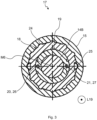
- the 3 shows the vibration decoupling device 17 in a sectional view along the section line III-III of FIG 2 .
- the spring element holder 18 is non-rotatably connected to the grip element 15 with the aid of teeth 24 .
- a connection using feather keys 25 can also be provided.
- the spring element holder 18 can also be glued to the grip element 15 .
- the sleeve-shaped or tubular spring element 19 is accommodated in the spring element holder 18.
- the spring element 19 is made of an elastomer, such as rubber, a thermoplastic polyurethane, a silicone material or the like.
- the spring element 19 is an elastomer spring element or can be referred to as such.
- the spring element 19 has a hollow-cylindrical geometry with an annular base area.
- the geometry of the spring element 19 extends along the axis of symmetry M6 in the longitudinal direction L19.
- the spring element 19 is included constructed rotationally symmetrical to the axis of symmetry M6.
- the spring element 19 can, for example, be glued to the spring element holder 18 or vulcanized onto it. This means that the spring element 19 can be materially connected to the spring element holder 18 . In the case of material connections, the connection partners are held together by atomic or molecular forces. Cohesive connections are non-detachable connections that can only be separated by destroying the connection means.
- the connecting element 14 or the base body 14B of the same is accommodated in the spring element 19 .
- the connecting element 14 can in turn be glued to the spring element 19 or this can be vulcanized onto the connecting element 14 .
- the spring element 19 comprises a multiplicity of receiving areas 26, 27 which extend in the longitudinal direction L19 and in which the adjusting elements 20, 21 are received.
- the receiving areas 26, 27 can be designed as bores extending in the longitudinal direction L19.
- the receiving areas 26, 27 can break through the entire spring element 19 along its entire length.
- the receiving areas 26, 27 can have any other desired geometry.
- the receiving areas 26, 27 can be polygonal, in particular triangular, square or rectangular.
- a multiplicity of such receiving areas 26, 27 are preferably provided, which are distributed uniformly around a circumference of the spring element 19.
- ten such receiving areas 26, 27 and accordingly also ten such setting elements 20, 21 are provided.
- the spring stiffness of the spring element 19 can be adjusted.
- the spring stiffness is to be understood here as the ratio of a force acting on the spring element 19 to the deflection of the spring element 19 caused thereby.
- the spring stiffness, spring constant, spring hardness or spring rate of the spring element 19 is adjusted in that the adjusting elements 20, 21 are pushed into the spring element 19 or pulled out of it.
- the adjustment elements 20, 21 are pushed into the spring element 19, its spring stiffness is increased.
- the adjusting elements 20, 21 are pulled out of the spring element 19, its spring stiffness is reduced. This process is reversible.
- the adjustment elements 20, 21 can be moved synchronously or asynchronously.
- the functionality of the vibration decoupling device 17 is explained below. Vibrations of different frequencies can occur in different applications of the hand-held power tool 1 . It is desirable that these vibrations or oscillations are not transmitted to the handle section 6 of the handle 5, or only in a damped manner, in order to improve the comfort for the user. Because the vibration decoupling device 17 can be controlled with the aid of the adjustment elements 20, 21, the spring stiffness of the spring element 19 can be changed so that the hand-held power tool 1 can always work at an optimal operating point and thus have a minimum of oscillations or vibrations at all operating points Handle portion 6 can be achieved. As a result, the handle 5 can be used for a wide variety of handheld power tools 1 in a wide variety of operating states.
- the setting elements 20, 21 can be operated manually by the user. Furthermore, a mechanical adjustment and/or a mechatronic adjustment can also take place. With a mechatronic adjustment, the advantage can be achieved that an optimal spring stiffness of the spring element 19 can be set on the basis of measured oscillations or vibrations. An adjusting element for displacing the adjusting elements 20, 21 can then be provided.
- the adjusting elements 20, 21 are preferably made of a material that allows the adjusting elements 20, 21 to be pushed into the spring element 19 and pulled out again easily and without the risk of kinking, while the receiving areas 26, 27 provided in the spring element 19 fill up or release.
- the adjusting elements 20, 21 can, for example, be steel wires or shaped pieces made of plastic.
- the adjustment elements 20, 21 can be round. However, the adjustment elements 20, 21 can also have any geometry. For example, the adjustment elements 20, 21 can have a polygonal or oval cross section.
Landscapes
- Engineering & Computer Science (AREA)
- Mechanical Engineering (AREA)
- Percussive Tools And Related Accessories (AREA)
Description
- Die vorliegende Erfindung betrifft einen Handgriff für eine Handwerkzeugmaschine und eine Handwerkzeugmaschine mit einem derartigen Handgriff. Ein Handgriff gemäß dem Oberbegriff des Anspruchs 1 ist bereits aus der
DE 10 2007 060042 A1 bekannt. - Eine Handwerkzeugmaschine, wie beispielsweise eine Bohrmaschine, kann einen Haupthandgriff, der hinten an der Handwerkzeugmaschine angeordnet ist, und einen Seitenhandgriff, der vorderseitig an der Handwerkzeugmaschine angeordnet ist, umfassen. Der Seitenhandgriff ist in der Regel lösbar an der Handwerkzeugmaschine befestigt. Um das Übertragen von Schwingungen oder Vibrationen von der Handwerkzeugmaschine auf den Seitenhandgriff zu verhindern oder zumindest zu reduzieren, können Schäume oder Elastomere als Federn eingesetzt werden. Die Auslegung einer derartigen Feder erfolgt dabei in der Regel auf nur eine zu isolierende Frequenz.
- Ändert sich bei dem Einsatz der Handwerkzeugmaschine die Frequenz durch die Anwendung, die Einstellung der Handwerkzeugmaschine oder die Arbeitsfrequenz, so können diese Federn nicht auf die unterschiedlichen Anwendungsfälle angepasst werden. Damit haben diese Systeme nur einen einzigen Anwendungsbereich, welcher hinsichtlich der Vibrationsisolation optimal abgestimmt ist. Treten bei unterschiedlichen Anwendungsbereichen unterschiedliche Frequenzen auf, so funktioniert das Isolationssystem nicht mehr optimal. Die Isolationsleistung nimmt ab, weil die Anregungsfrequenz nicht mehr zur Steifigkeit der verwendeten Feder passt. Ein und dasselbe Isolationssystem kann damit oft nur bei einem Typ von Handwerkzeugmaschinen eingesetzt werden und erreicht seine optimale Leistung nur bei einem speziellen Anwendungsbereich. Damit ist das Potenzial für eine gute Vibrationsisolation oftmals nicht vollumfänglich ausgeschöpft.
- Eine Aufgabe der vorliegenden Erfindung ist es, einen verbesserten Handgriff für eine Handwerkzeugmaschine bereitzustellen.
- Demgemäß wird ein Handgriff für eine Handwerkzeugmaschine vorgeschlagen. Der Handgriff umfasst einen Griffabschnitt, der von einem Benutzer umgreifbar ist, einen Befestigungsabschnitt, mit dessen Hilfe der Handgriff an der Handwerkzeugmaschine befestigbar ist, und eine Schwingungsentkopplungseinrichtung, die dazu eingerichtet ist, auf den Befestigungsabschnitt wirkende Schwingungen von dem Griffabschnitt zu entkoppeln, wobei die Schwingungsentkopplungseinrichtung ein Federelement mit einer einstellbaren Federsteifigkeit aufweist.
- Dadurch, dass die Federsteifigkeit des Federelements einstellbar ist, kann die Schwingungsentkopplungseinrichtung für unterschiedlichste Anwendungsfälle unterschiedlichster Handwerkzeugmaschinen eingesetzt werden. Hierdurch vergrößert sich das Einsatzgebiet für den Handgriff signifikant. Weiterhin kann auf das Vorhalten verschiedener Handgriffe mit unterschiedlichster Schwingungsentkopplungseignung verzichtet werden.
- Unter der "Federsteifigkeit" ist vorliegend das Verhältnis einer auf das Federelement wirkenden Kraft zur dadurch bewirkten Auslenkung des Federelements zu verstehen. Die "Auslenkung" kann dabei eine Kompression oder Expansion des Federelements sein. Die Federsteifigkeit kann auch als Federkonstante, Federhärte oder Federrate bezeichnet werden. Darunter, dass die Schwingungsentkopplungseinrichtung dazu eingerichtet ist, die Schwingungen von dem Griffabschnitt zu "entkoppeln", ist zu versehen, dass die Schwingungsentkopplungseinrichtung dazu eingerichtet ist, das Übertragen von Schwingungen oder Vibrationen von dem Befestigungsabschnitt auf den Griffabschnitt zu verhindern oder zumindest zu reduzieren. Insbesondere ist die Schwingungsentkopplungseinrichtung dazu eingerichtet, eine Schwingungsamplitude zu reduzieren. Der Handgriff ist insbesondere ein Seitenhandgriff der Handwerkzeugmaschine oder kann als solcher bezeichnet werden.
- Gemäß einer Ausführungsform ist die Schwingungsentkopplungseinrichtung zumindest abschnittsweise innerhalb eines Griffelements des Handgriffs angeordnet.
- Das Griffelement ist vorzugsweise rohrförmig. Dadurch, dass die Schwingungsentkopplungseinrichtung in dem Griffelement aufgenommen ist, kann ein besonders kompakter Aufbau des Handgriffs erzielt werden. Weiterhin ist die Schwingungsentkopplungseinrichtung dadurch vor Beschädigungen geschützt. Das Griffelement kann zumindest abschnittsweise aus einem elastisch verformbaren Material, wie beispielsweise einem elastischen Kunststoffmaterial, Gummi oder Kork, gefertigt sein. Dies erhöht den Bedienkomfort. Im Betrieb der Handwerkzeugmaschine wird das Griffelement von dem Benutzer umgriffen.
- Gemäß einer weiteren Ausführungsform ist das Federelement aus einem Elastomer, insbesondere aus einem Gummiwerkstoff, einem thermoplastischen Elastomer oder einem Silikonwerkstoff, gefertigt.
- Das Federelement kann auch als Elastomerfederelement, Elastomerfeder oder Elastomerelement bezeichnet werden. Das Federelement kann aus einem beliebigen anderen elastischen verformbaren Werkstoff gefertigt werden. Das Federelement kann aus einem aufgeschäumten Material gefertigt sein. Das heißt, das Federelement kann Poren aufweisen. Das Material kann offenporig oder geschlossenporig sein. Das Material kann ein Schaum sein. Alternativ kann das Federelement auch massiv sein. Das Federelement kann auch einen metallischen Werkstoff umfassen. Beispielsweise kann das Federelement ein Drahtgeflecht, eine verstellbare Blattfeder oder dergleichen sein.
- Gemäß einer weiteren Ausführungsform ist die Federsteifigkeit des Federelements stufenlos einstellbar.
- Das heißt, die Federsteifigkeit ist nicht nur in wenigen Stufen gestuft verstellbar, sondern kann zwischen einer maximal möglichen Federsteifigkeit und einer minimal möglichen Federsteifigkeit stufenlos in eine Vielzahl an Federsteifigkeiten einstellbar sein. Die Einstellbarkeit der Federsteifigkeit ist reversibel. Das heißt, die Federsteifigkeit des Federelements kann erhöht und dann wieder reduziert und dementsprechend auch wieder erhöht werden.
- Gemäß einer weiteren Ausführungsform ist das Federelement rohrförmig.
- Das Federelement weist vorzugsweise eine hohlzylinderförmige Geometrie mit einer ringförmigen Basisfläche auf.
- Gemäß einer weiteren Ausführungsform weist die Schwingungsentkopplungseinrichtung ein Verbindungselement auf, das zumindest abschnittsweise in dem Federelement aufgenommen ist und das den Befestigungsabschnitt mit dem Griffabschnitt verbindet.
- Vorzugsweise ist das Verbindungselement stoffschlüssig mit dem Federelement verbunden. Bei stoffschlüssigen Verbindungen werden die Verbindungspartner durch atomare oder molekulare Kräfte zusammengehalten. Stoffschlüssige Verbindungen sind nicht lösbare Verbindungen, die sich nur durch Zerstörung der Verbindungsmittel und/oder Verbindungspartner trennen lassen. Stoffschlüssig kann beispielsweise durch Kleben oder Vulkanisieren verbunden werden. Beispielsweise ist das Federelement an das Verbindungselement anvulkanisiert oder mit diesem verklebt. Das Verbindungselement kann einen zylinderförmigen Basiskörper aufweisen, der in dem Federelement aufgenommen ist. Oberseitig aus dem zylinderförmigen Basisabschnitt kann sich ein Gewindebolzen herauserstrecken, der mit Hilfe eines Befestigungselements, beispielsweise einer Sechskantmutter, mit dem Befestigungsabschnitt verschraubt ist.
- Gemäß einer weiteren Ausführungsform weist die Schwingungsentkopplungseinrichtung einen innerhalb des Griffabschnitts angeordneten Federelementhalter auf, in dem das Federelement aufgenommen ist.
- Der Federelementhalter ist vorzugsweise rohrförmig oder hülsenförmig. Der Federelementhalter ist in dem Griffelement des Griffabschnitts aufgenommen und fest mit diesem verbunden. Beispielsweise kann zwischen dem Federelementhalter und dem Griffelement eine Verzahnung vorgesehen sein. Ferner kann der Federelementhalter auch mit dem Griffelement verklebt sein.
- Gemäß einer weiteren Ausführungsform verbindet das Federelement das Verbindungselement mit dem Federelementhalter, insbesondere stoffschlüssig. Beispielsweise ist das Federelement mit dem Verbindungselement und dem Federelementhalter verklebt oder an diese anvulkanisiert. Das Federelement ist so zwischen dem Federelementhalter und dem Verbindungselement angeordnet, wobei das Verbindungselement insbesondere in dem Federelement und das Federelement insbesondere in dem Federelementhalter angeordnet ist. Dies ergibt einen schichtweisen Aufbau. Hierdurch kann ein besonders kompakter Aufbau erreicht werden.
- Erfindungsgemäß weist die Schwingungsentkopplungseinrichtung ein Einstellelement zum Einstellen der Federsteifigkeit des Federelements auf.
- Das Federelement ist zum Einstellen der Federsteifigkeit des Federelements entlang einer Längsrichtung des Federelements linear verschieblich. Die Längsrichtung kann dabei mit einer Symmetrieachse des Griffabschnitts übereinstimmen oder parallel zu dieser orientiert sein.
- Erfindungsgemäß weist das Federelement einen sich in einer Längsrichtung des Federelements erstreckenden Aufnahmebereich auf, in dem das Einstellelement zumindest abschnittsweise aufgenommen ist.
- Wie zuvor erwähnt, kann das Einstellelement zum Einstellen der Federsteifigkeit linear in dem Aufnahmebereich verschoben werden. Je weiter das Einstellelement in den Aufnahmebereich hineingeschoben ist, desto größer ist die Federsteifigkeit, und je weiter das Einstellelement aus dem Aufnahmebereich herausgezogen ist, desto geringer ist die Federsteifigkeit. Der Aufnahmebereich kann eine sich entlang der Längsrichtung erstreckende Bohrung oder ein sich entlang der Längsrichtung erstreckender Durchbruch sein.
- Gemäß einer weiteren Ausführungsform ist die Federsteifigkeit des Federelements dadurch vergrößerbar, dass das Einstellelement entlang der Längsrichtung in den Aufnahmebereich hineinverlagert wird, wobei die Federsteifigkeit des Federelements dadurch verkleinerbar ist, dass das Einstellelement entlang der Längsrichtung aus dem Aufnahmebereich herausverlagert wird.
- Das Hineinverlagern und das Herausverlagern können dabei - wie zuvor erwähnt - stufenlos erfolgen, so dass die Federsteifigkeit des Federelements stufenlos einstellbar ist.
- Erfindungsgemäß umfasst der Handgriff eine Vielzahl an Aufnahmebereichen und eine Vielzahl an Einstellelementen, die gleichmäßig voneinander beabstandet um einen Umfang des Federelements verteilt angeordnet sind.
- In einer nicht erfindungsgemäßen Alternative können die Aufnahmebereiche und die Einstellelemente auch ungleichmäßig voneinander beabstandet um den Umfang des Federelements verteilt angeordnet sein. Die Einstellelemente und die Aufnahmebereiche können alle eine identische Geometrie oder unterschiedliche Geometrien aufweisen. Jedem Aufnahmebereich ist dabei ein Einstellelement und umgekehrt zugeordnet.
- Gemäß einer weiteren Ausführungsform ist das Einstellelement stabförmig und weist einen kreisrunden, ovalen oder vieleckigen, insbesondere rechteckigen, dreieckigen oder quadratischen Querschnitt auf.
- Die Geometrie des Einstellelements ist beliebig. Jedes Einstellelement kann einen Betätigungsbereich aufweisen. Der Betätigungsbereich kann beispielsweise ein abgekanteter Endabschnitt des Betätigungselements sein. Der Betätigungsbereich kann beispielsweise manuell betätigt werden.
- Gemäß einer weiteren Ausführungsform erfolgt ein Einstellen der Federsteifigkeit des Federelements manuell, mechanisch oder mechatronisch.
- Das heißt, der Benutzer kann durch ein Verschieben der Einstellelemente die Federsteifigkeit des Federelements manuell anpassen. Ferner können die Einstellelemente auch so mechanisch angesteuert werden, dass dann, wenn eine vorgegebene Schwingungsamplitude überschritten wird, die Einstellelemente mechanisch verschoben werden, um die Federsteifigkeit anzupassen. Bei einem mechatronischen Antrieb kann auf der Grundlage gemessener Vibrationen mit Hilfe eines Stellelements, welches die Einstellelemente verlagert, eine optimale Federsteifigkeit des Federelements eingestellt werden. Die Einstellelemente sind vorzugsweise stabförmig und werden aus einem Werkstoff hergestellt, der es ermöglicht, die Einstellelemente aus dem Federelement herauszuziehen und in dieses einzuschieben. Als Einstellelemente können beispielsweise Stahldrähte oder Formstücke aus Kunststoff zum Einsatz kommen.
- Ferner wird eine Handwerkzeugmaschine mit einem derartigen Handgriff vorgeschlagen.
- Die Handwerkzeugmaschine kann beispielsweise ein Bohrhammer, ein Meißelhammer, ein Kernbohrer, eine Säge, eine Schleifmaschine, ein Schrauber, ein Bolzenschubwerkzeug oder dergleichen sein. Die Handwerkzeugmaschine weist vorzugsweise ein Gehäuse mit einem Hauptgriff und den zuvor erläuterten Handgriff auf. Der Handgriff ist vorzugsweise seitlich mit dem Gehäuse verbunden. Der Handgriff kann daher auch als Seitenhandgriff bezeichnet werden. Der Handgriff ist lösbar mit einem zylinderförmigen Befestigungsabschnitt des Gehäuses verbunden. Der Handgriff kann auf den Befestigungsabschnitt des Gehäuses aufgeschoben und dann durch ein Verdrehen des Griffabschnitts gegenüber dem Befestigungsabschnitt an diesem fixiert werden. Umgekehrt kann der Handgriff auch durch ein Entspannen des Befestigungsabschnitts wieder von der Handwerkzeugmaschine gelöst werden.
- Die nachfolgende Beschreibung erläutert die Erfindung anhand von exemplarischen Ausführungsformen und Figuren. In den Figuren zeigt:
- Fig. 1
- eine schematische Ansicht einer Ausführungsform einer Handwerkzeugmaschine;
- Fig. 2
- eine schematische Schnittansicht einer Ausführungsform eines Handgriffs für die Handwerkzeugmaschine gemäß der Schnittlinie II-II der
Fig. 1 ; und - Fig. 3
- eine vergrößerte schematische Schnittansicht des Handgriffs gemäß der Schnittlinie III-III der
Fig. 2 . - Gleiche oder funktionsgleiche Elemente werden durch gleiche Bezugszeichen in den Figuren indiziert, soweit nichts anderes angegeben ist.
-
Fig. 1 zeigt eine schematische Ansicht einer Ausführungsform einer Handwerkzeugmaschine 1. Die Handwerkzeugmaschine 1 kann beispielsweise ein Bohrhammer, ein Meißelhammer, ein Kernbohrer, eine Säge, eine Schleifmaschine, ein Schrauber, ein Bolzenschubwerkzeug oder dergleichen sein. - Die Handwerkzeugmaschine 1 umfasst ein Gehäuse 2, an dem beispielsweise ein nicht gezeigter Akkumulator befestigt ist. Alternativ kann auch ein Netzkabel an dem Gehäuse 2 vorgesehen sein, das mit einer Steckdose verbindbar ist. Weiterhin umfasst das Gehäuse 2 einen nicht gezeigten Haupthandgriff, der in der Orientierung der
Fig. 1 rechts angeordnet ist. Ferner ist eine Befestigungsvorrichtung 3 zum Befestigen eines Werkzeugs, insbesondere eines Schneidwerkzeugs, wie beispielsweise eines Bohrers, an der Handwerkzeugmaschine 1 vorgesehen. Die Befestigungsvorrichtung 3 ist in der Orientierung derFig. 1 links angeordnet. Die Befestigungsvorrichtung 3 ist beispielsweise ein Spannfutter oder Bohrfutter. Das Gehäuse 2 umfasst einen Befestigungsabschnitt 4. Der Befestigungsabschnitt 4 ist im Querschnitt bevorzugt zylinderförmig, insbesondere kreiszylinderförmig. - An dem Befestigungsabschnitt 4 ist ein Handgriff 5 lösbar befestigt. "Lösbar" bedeutet hierbei, dass der Handgriff 5 von dem Befestigungsabschnitt 4 getrennt und wieder mit diesem verbunden werden kann. Der Handgriff 5 kann auch drehbar an dem Befestigungsabschnitt 4 angebracht sein. Beispielsweise kann der Handgriff 5 in der Orientierung der
Fig. 1 von links nach rechts auf den Befestigungsabschnitt 4 aufgeschoben und von rechts nach links von dem Befestigungsabschnitt 4 abgezogen werden. Der Handgriff 5 ist insbesondere ein sogenannter Seitenhandgriff oder kann als Seitenhandgriff bezeichnet werden. Der Handgriff 5 umfasst einen Griffabschnitt 6, der zum Bedienen der Handwerkzeugmaschine 1 von einem Benutzer umgreifbar ist, sowie einen vorzugsweise ringförmigen Befestigungsabschnitt 7, der lösbar mit dem Befestigungsabschnitt 4 des Gehäuses 2 verbunden werden kann. - Wie die
Fig. 2 zeigt, umfasst der Befestigungsabschnitt 7 ein Spannband 8. Das Spannband 8 kann beispielsweise ein Stahlband sein. Weiterhin umfasst der Befestigungsabschnitt 7 ein Auflageelement 9. Das Spannband 8 und das Auflageelement 9 bilden einen kreisförmigen Aufnahmebereich 10 für den Befestigungsabschnitt 4 des Gehäuses 2 der Handwerkzeugmaschine 1. Weiterhin umfasst der Befestigungsabschnitt 7 ein Basiselement 11, ein Spannelement 12 sowie ein in dem Spannelement 12 aufgenommenes Befestigungselement 13. Das Befestigungselement 13 kann beispielsweise eine Sechskantmutter sein. Das Auflageelement 9, das Spannelement 12 und das Befestigungselement 13 sind zumindest abschnittsweise in dem Basiselement 11 aufgenommen. - Das Befestigungselement 13 ist mit einem dem Griffabschnitt 6 zugeordneten Verbindungselement 14 verschraubt. Das Verbindungselement 14 weist hierzu einen Gewindebolzen 14A auf, der durch das Basiselement 11, das Spannband 8, das Spannelement 12 und das Befestigungselement 13 hindurchgeführt ist. Durch ein Verdrehen des Griffabschnitts 6 gegenüber dem Befestigungsabschnitt 7 kann somit das Befestigungselement 13 zum Spannen des Spannbands 8 angezogen und zum Lösen des Spannbands 8 gelockert werden. Hierdurch kann der Befestigungsabschnitt 7 lösbar mit dem Befestigungsabschnitt 4 der Handwerkzeugmaschine 1 verbunden werden. Das Verbindungselement 14 umfasst ferner einen Basiskörper 14B, aus dem sich stirnseitig der Gewindebolzen 14A herauserstreckt.
- Der Griffabschnitt 6 umfasst ein Griffelement 15. Das Griffelement 15 ist vorzugsweise rotationssymmetrisch zu einer Symmetrieachse M6 des Griffabschnitts 6 aufgebaut. Das Griffelement 15 kann zumindest abschnittsweise aus einem elastisch verformbaren Material gefertigt sein. Im Betrieb der Handwerkzeugmaschine 1 wird das Griffelement 15 zumindest abschnittsweise von einer Hand des Benutzers umgriffen. Das Griffelement 15 kann rohrförmig ausgebildet sein. In dem Griffelement 15 ist das Verbindungselement 14, insbesondere der Basiskörper 14B des Verbindungselements 14, zumindest abschnittsweise aufgenommen. Zwischen dem Griffelement 15 und dem Basiselement 11 kann eine Scheibe 16 angeordnet sein. Die Scheibe 16 ist beispielsweise eine Unterlegscheibe.
- In dem Griffelement 15 aufgenommen ist eine Schwingungsentkopplungseinrichtung 17 des Handgriffs 5. Die Schwingungsentkopplungseinrichtung 17 umfasst einen hülsenförmigen oder rohrförmigen Federelementhalter 18, der in dem Griffelement 15 aufgenommen ist und der dem Befestigungsabschnitt 7 zugewandt ist. Der Federelementhalter 18 kann beispielsweise ein Kunststoffbauteil sein. Der Federelementhalter 18 ist drehfest mit dem Griffelement 15 verbunden. In dem Federelementhalter 18 aufgenommen ist das ebenfalls der Schwingungsentkopplungseinrichtung 17 zugeordnete Verbindungselement 14, insbesondere der Basiskörper 14B desselben.
- Die Schwingungsentkopplungseinrichtung 17 umfasst weiterhin ein Federelement 19, dessen Federsteifigkeit einstellbar ist, sowie mehrere Einstellelemente 20, 21, mit deren Hilfe die Federsteifigkeit des Federelements 19 eingestellt werden kann. Dem Federelement 19 ist eine Längsrichtung L19 zugeordnet. Die Längsrichtung L19 verläuft parallel zu der Symmetrieachse M6. Die Längsrichtung L19 kann mit der Symmetrieachse M6 übereinstimmen. Die Längsrichtung L19 kann in der Orientierung der
Fig. 2 von unten nach oben oder von oben nach unten orientiert sein. Die Einstellelemente 20, 21 können beispielsweise als Stahldrähte oder Kunststoffkörper ausgebildet sein. Jedem Einstellelement 20, 21 ist ein Betätigungsbereich 22, 23 zugeordnet. Die Betätigungsbereiche 22, 23 können dadurch gebildet sein, dass das jeweilige Einstellelement 20, 21 endseitig um 90° umgebogen oder abgekantet wird. - Die
Fig. 3 zeigt die Schwingungsentkopplungseinrichtung 17 in einer Schnittansicht gemäß der Schnittlinie III-III derFig. 2 . Wie dieFig. 3 zeigt, ist der Federelementhalter 18 mit Hilfe einer Verzahnung 24 drehfest mit dem Griffelement 15 verbunden. Zusätzlich kann noch eine Verbindung mit Hilfe von Passfedern 25 vorgesehen sein. Weiterhin kann der Federelementhalter 18 auch mit dem Griffelement 15 verklebt sein. In dem Federelementhalter 18 aufgenommen ist das hülsenförmige oder rohrförmige Federelement 19. Das Federelement 19 ist aus einem Elastomer, wie beispielsweise Gummi, einem thermoplastischen Polyurethan, einem Silikonwerkstoff oder dergleichen, gefertigt. - Das Federelement 19 ist ein Elastomerfederelement oder kann als solches bezeichnet werden. Das Federelement 19 weist eine hohlzylinderförmige Geometrie mit einer ringförmigen Grundfläche auf. Die Geometrie des Federelements 19 erstreckt sich entlang der Symmetrieachse M6 in der Längsrichtung L19. Das Federelement 19 ist dabei rotationssymmetrisch zu der Symmetrieachse M6 aufgebaut. Das Federelement 19 kann beispielsweise mit dem Federelementhalter 18 verklebt oder an diesen anvulkanisiert sein. Das heißt, das Federelement 19 kann stoffschlüssig mit dem Federelementhalter 18 verbunden sein. Bei stoffschlüssigen Verbindungen werden die Verbindungspartner durch atomare oder molekulare Kräfte zusammengehalten. Stoffschlüssige Verbindungen sind nicht lösbare Verbindungen, die sich nur durch Zerstörung der Verbindungsmittel trennen lassen.
- Wie die
Fig. 3 weiterhin zeigt, ist in dem Federelement 19 das Verbindungselement 14 beziehungsweise der Basiskörper 14B desselben aufgenommen. Das Verbindungselement 14 kann wiederum mit dem Federelement 19 verklebt oder dieses kann an das Verbindungselement 14 anvulkanisiert sein. Das Federelement 19 umfasst eine Vielzahl an sich in der Längsrichtung L19 erstreckenden Aufnahmebereichen 26, 27, in denen die Einstellelemente 20, 21 aufgenommen sind. Die Aufnahmebereiche 26, 27 können als sich in der Längsrichtung L19 erstreckende Bohrungen ausgebildet sein. Dabei können die Aufnahmebereiche 26, 27 das gesamte Federelement 19 auf seiner gesamten Länge durchbrechen. Die Aufnahmebereiche 26, 27 können, wie in derFig. 3 gezeigt, als kreisrunde Bohrungen ausgebildet sein. - Alternativ können die Aufnahmebereiche 26, 27 jedoch jede andere beliebige Geometrie aufweisen. Beispielsweise können die Aufnahmebereiche 26, 27 vieleckig, insbesondere dreieckig, quadratisch oder rechteckig, ausgebildet sein. Bevorzugt ist eine Vielzahl derartiger Aufnahmebereiche 26, 27 vorgesehen, die gleichmäßig um einen Umfang des Federelements 19 verteilt angeordnet sind. Beispielsweise sind zehn derartige Aufnahmebereiche 26, 27 und dementsprechend auch zehn derartige Einstellelemente 20, 21 vorgesehen. Mit Hilfe der Einstellelemente 20, 21 kann die Federsteifigkeit des Federelements 19 verstellt werden. Unter der Federsteifigkeit ist vorliegend das Verhältnis einer auf das Federelement 19 wirkenden Kraft zur dadurch bewirkten Auslenkung des Federelements 19 zu verstehen.
- Die Federsteifigkeit, Federkonstante, Federhärte oder auch Federrate des Federelements 19 wird dadurch verstellt, dass die Einstellelemente 20, 21 in das Federelement 19 hineingeschoben oder aus diesem herausgezogen werden. Bei einem Hineinschieben der Einstellelemente 20, 21 in das Federelement 19 wird dessen Federsteifigkeit vergrößert. Bei einem Herausziehen der Einstellelemente 20, 21 aus dem Federelement 19 wird dessen Federsteifigkeit verkleinert. Dieser Vorgang ist reversibel. Die Einstellelemente 20, 21 können dabei synchron oder asynchron bewegt werden.
- Die Funktionalität der Schwingungsentkopplungseinrichtung 17 wird nachfolgend erläutert. Bei unterschiedlichen Anwendungen der Handwerkzeugmaschine 1 können Vibrationen unterschiedlicher Frequenzen auftreten. Es ist dabei wünschenswert, dass diese Vibrationen oder Schwingungen nicht oder nur gedämpft auf den Griffabschnitt 6 des Handgriffs 5 übertragen werden, um den Komfort für den Benutzer zu verbessern. Dadurch, dass die Schwingungsentkopplungseinrichtung 17 mit Hilfe der Einstellelemente 20, 21 ansteuerbar ist, kann die Federsteifigkeit des Federelements 19 verändert werden, so dass die Handwerkzeugmaschine 1 immer in einem optimalen Betriebspunkt arbeiten kann und somit in allen Betriebspunkten ein Minimum an Schwingungen oder Vibrationen an dem Griffabschnitt 6 erzielt werden kann. Hierdurch kann der Handgriff 5 für unterschiedlichste Handwerkzeugmaschinen 1 in unterschiedlichsten Betriebszuständen eingesetzt werden.
- Die Einstellelemente 20, 21 können dabei von dem Benutzer manuell betätigt werden. Weiterhin kann auch eine mechanische Verstellung und/oder eine mechatronische Verstellung erfolgen. Bei einer mechatronischen Verstellung kann der Vorteil erreicht werden, dass auf der Grundlage gemessener Schwingungen oder Vibrationen eine optimale Federsteifigkeit des Federelements 19 eingestellt werden kann. Es kann dann ein Stellelement zum Verlagern der Einstellelemente 20, 21 vorgesehen sein.
- Die Einstellelemente 20, 21 sind vorzugsweise aus einem Werkstoff hergestellt, der es erlaubt, die Einstellelemente 20, 21 einfach und ohne die Gefahr eines Abknickens in das Federelement 19 einzuschieben und wieder aus diesem herauszuziehen und dabei die in dem Federelement 19 vorgesehene Aufnahmebereiche 26, 27 aufzufüllen oder freizugeben. Die Einstellelemente 20, 21 können beispielsweise Stahldrähte oder Formstücke aus Kunststoff sein. Die Einstellelemente 20, 21 können dabei rund sein. Die Einstellelemente 20, 21 können jedoch auch eine beliebige Geometrie aufweisen. Beispielsweise können die Einstellelemente 20, 21 einen vieleckigen oder ovalen Querschnitt aufweisen.
-
- 1
- Handwerkzeugmaschine
- 2
- Gehäuse
- 3
- Befestigungsvorrichtung
- 4
- Befestigungsabschnitt
- 5
- Handgriff
- 6
- Griffabschnitt
- 7
- Befestigungsabschnitt
- 8
- Spannband
- 9
- Auflageelement
- 10
- Aufnahmebereich
- 11
- Basiselement
- 12
- Spannelement
- 13
- Befestigungselement
- 14
- Verbindungselement
- 14A
- Gewindebolzen
- 14B
- Basiskörper
- 15
- Griffelement
- 16
- Schreibe
- 17
- Schwingungsentkopplungseinrichtung
- 18
- Federelementhalter
- 19
- Federelement
- 20
- Einstellelement
- 21
- Einstellelement
- 22
- Betätigungsbereich
- 23
- Betätigungsbereich
- 24
- Verzahnung
- 25
- Passfeder
- 26
- Aufnahmebereich
- 27
- Aufnahmebereich
- L19
- Längsrichtung
- M6
- Symmetrieachse
Claims (12)
- Handgriff (5) für eine Handwerkzeugmaschine (1), mit einem Griffabschnitt (6), der von einem Benutzer umgreifbar ist, einem Befestigungsabschnitt (7), mit dessen Hilfe der Handgriff (5) an der Handwerkzeugmaschine (1) befestigbar ist, und einer Schwingungsentkopplungseinrichtung (17), die dazu eingerichtet ist, auf den Befestigungsabschnitt (7) wirkende Schwingungen von dem Griffabschnitt (6) zu entkoppeln, wobei die Schwingungsentkopplungseinrichtung (17) ein Federelement (19) mit einer einstellbaren Federsteifigkeit aufweist
wobei die Schwingungsentkopplungseinrichtung (17) ein Einstellelement (20, 21) zum Einstellen der Federsteifigkeit des Federelements (19) aufweist, wobei das Federelement (19) einen sich in einer Längsrichtung (L19) des Federelements (19) erstreckenden Aufnahmebereich (26, 27) aufweist, in dem das Einstellelement (20, 21) zumindest abschnittsweise aufgenommen ist dadurch gekennzeichnet, dass eine Vielzahl an Aufnahmebereichen (26, 27) und eine Vielzahl an Einstellelementen (20, 21), die gleichmäßig voneinander beabstandet um einen Umfang des Federelements (19) verteilt angeordnet sind. - Handgriff nach Anspruch 1,
dadurch gekennzeichnet, dass die Schwingungsentkopplungseinrichtung (17) zumindest abschnittsweise innerhalb eines Griffelements (15) des Handgriffs (5) angeordnet ist. - Handgriff nach Anspruch 1 oder 2,
dadurch gekennzeichnet, dass das Federelement (19) aus einem Elastomer, insbesondere aus einem Gummiwerkstoff, einem thermoplastischen Elastomer oder einem Silikonwerkstoff, gefertigt ist. - Handgriff nach einem der Ansprüche 1 - 3,
dadurch gekennzeichnet, dass die Federsteifigkeit des Federelements (19) stufenlos einstellbar ist. - Handgriff nach einem der Ansprüche 1 - 4,
dadurch gekennzeichnet, dass das Federelement (19) rohrförmig ist. - Handgriff nach Anspruch 5,
dadurch gekennzeichnet, dass die Schwingungsentkopplungseinrichtung (17) ein Verbindungselement (14) aufweist, das zumindest abschnittsweise in dem Federelement (19) aufgenommen ist und das den Befestigungsabschnitt (7) mit dem Griffabschnitt (6) verbindet. - Handgriff nach Anspruch 6,
dadurch gekennzeichnet, dass die Schwingungsentkopplungseinrichtung (17) einen innerhalb des Griffabschnitts (6) angeordneten Federelementhalter (18) aufweist, in dem das Federelement (19) aufgenommen ist. - Handgriff nach Anspruch 7,
dadurch gekennzeichnet, dass das Federelement (19) das Verbindungselement (14) mit dem Federelementhalter (18), insbesondere stoffschlüssig, verbindet. - Handgriff nach Anspruch 1,
dadurch gekennzeichnet, dass die Federsteifigkeit des Federelements (19) dadurch vergrößerbar ist, dass das Einstellelement (20, 21) entlang der Längsrichtung (L19) in den Aufnahmebereich (26, 27) hineinverlagert wird, und dass die Federsteifigkeit des Federelements (19) dadurch verkleinerbar ist, dass das Einstellelement (20, 21) entlang der Längsrichtung (L19) aus dem Aufnahmebereich (26, 27) herausverlagert wird. - Handgriff nach einem der Ansprüche 1,
dadurch gekennzeichnet, dass das Einstellelement (20, 21) stabförmig ist und einen kreisrunden, ovalen oder vieleckigen, insbesondere rechteckigen, dreieckigen oder quadratischen, Querschnitt aufweist. - Handgriff nach einem der Ansprüche 1 - 10,
dadurch gekennzeichnet, dass ein Einstellen der Federsteifigkeit des Federelements (19) manuell, mechanisch oder mechatronisch erfolgt. - Handwerkzeugmaschine (1) mit einem Handgriff (5) nach einem der Ansprüche 1 - 11.
Applications Claiming Priority (2)
| Application Number | Priority Date | Filing Date | Title |
|---|---|---|---|
| EP18183844.2A EP3597370A1 (de) | 2018-07-17 | 2018-07-17 | Handgriff und handwerkzeugmaschine |
| PCT/EP2019/068562 WO2020016078A1 (de) | 2018-07-17 | 2019-07-10 | Handgriff und handwerkzeugmaschine |
Publications (2)
| Publication Number | Publication Date |
|---|---|
| EP3823793A1 EP3823793A1 (de) | 2021-05-26 |
| EP3823793B1 true EP3823793B1 (de) | 2023-03-29 |
Family
ID=62981047
Family Applications (2)
| Application Number | Title | Priority Date | Filing Date |
|---|---|---|---|
| EP18183844.2A Withdrawn EP3597370A1 (de) | 2018-07-17 | 2018-07-17 | Handgriff und handwerkzeugmaschine |
| EP19737110.7A Active EP3823793B1 (de) | 2018-07-17 | 2019-07-10 | Handgriff und handwerkzeugmaschine |
Family Applications Before (1)
| Application Number | Title | Priority Date | Filing Date |
|---|---|---|---|
| EP18183844.2A Withdrawn EP3597370A1 (de) | 2018-07-17 | 2018-07-17 | Handgriff und handwerkzeugmaschine |
Country Status (4)
| Country | Link |
|---|---|
| US (1) | US11958178B2 (de) |
| EP (2) | EP3597370A1 (de) |
| CN (1) | CN112313040B (de) |
| WO (1) | WO2020016078A1 (de) |
Families Citing this family (3)
| Publication number | Priority date | Publication date | Assignee | Title |
|---|---|---|---|---|
| CN219311210U (zh) | 2021-05-14 | 2023-07-07 | 创科无线普通合伙 | 一种用于动力工具的手柄 |
| JP7776308B2 (ja) * | 2021-10-29 | 2025-11-26 | 株式会社マキタ | 撹拌機 |
| JP2024140155A (ja) * | 2023-03-28 | 2024-10-10 | 株式会社マキタ | 作業工具用補助ハンドル |
Family Cites Families (12)
| Publication number | Priority date | Publication date | Assignee | Title |
|---|---|---|---|---|
| US4783038A (en) | 1987-07-07 | 1988-11-08 | Aeroflex International Incorporated | Isolator apparatus |
| DE19848126A1 (de) * | 1998-10-19 | 2000-04-27 | Wilhelm Kaechele Gmbh Elastome | Schwingungsgedämpfter Handgriff |
| DE102007012300A1 (de) * | 2006-09-27 | 2008-04-03 | Robert Bosch Gmbh | Handgriff |
| DE102006061247A1 (de) * | 2006-12-22 | 2008-06-26 | Robert Bosch Gmbh | Handgriff |
| DE102007048887B4 (de) * | 2007-10-11 | 2017-10-26 | Andreas Stihl Ag & Co. Kg | Handgeführtes Arbeitsgerät |
| DE102007060042A1 (de) * | 2007-12-13 | 2009-06-18 | Robert Bosch Gmbh | Zusatzhandgriffvorrichtung |
| DE102007062714A1 (de) * | 2007-12-27 | 2009-07-02 | Robert Bosch Gmbh | Handgriff |
| EP2123406B1 (de) * | 2008-05-19 | 2011-12-21 | AEG Electric Tools GmbH | Vibrationsgedämpfter Halter für Zusatzhandgriff |
| DE202010002296U1 (de) * | 2010-02-11 | 2011-08-26 | Illinois Tool Works Inc. | Handgriffanordnung |
| DE102010042551A1 (de) * | 2010-10-18 | 2012-04-19 | Robert Bosch Gmbh | Handwerkzeugmaschinenentkopplungseinheit |
| JP5588029B2 (ja) * | 2013-01-23 | 2014-09-10 | 株式会社マキタ | 打撃工具用サイドハンドル及び打撃工具 |
| EP3127658A1 (de) * | 2015-08-06 | 2017-02-08 | HILTI Aktiengesellschaft | Seitenhandgriff |
-
2018
- 2018-07-17 EP EP18183844.2A patent/EP3597370A1/de not_active Withdrawn
-
2019
- 2019-07-10 EP EP19737110.7A patent/EP3823793B1/de active Active
- 2019-07-10 US US17/254,121 patent/US11958178B2/en active Active
- 2019-07-10 WO PCT/EP2019/068562 patent/WO2020016078A1/de not_active Ceased
- 2019-07-10 CN CN201980039915.4A patent/CN112313040B/zh active Active
Also Published As
| Publication number | Publication date |
|---|---|
| EP3823793A1 (de) | 2021-05-26 |
| US11958178B2 (en) | 2024-04-16 |
| EP3597370A1 (de) | 2020-01-22 |
| WO2020016078A1 (de) | 2020-01-23 |
| CN112313040B (zh) | 2023-11-21 |
| US20210347030A1 (en) | 2021-11-11 |
| CN112313040A (zh) | 2021-02-02 |
Similar Documents
| Publication | Publication Date | Title |
|---|---|---|
| DE19525251C2 (de) | Elastisch kompressibles Vibrationsisolierelement für ein vibrierendes Werkzeug | |
| EP1800807B1 (de) | Handgriff mit Vibrationsminderungseinrichtung | |
| EP2241408B1 (de) | Seitenhandgriff | |
| EP3823793B1 (de) | Handgriff und handwerkzeugmaschine | |
| EP1955826B1 (de) | Handwerkzeugmaschine mit zumindest einem Handgriff | |
| DE10034437B4 (de) | Handgeführtes Arbeitsgerät | |
| EP2069109A1 (de) | Elektrowerkzeugmaschine mit schwingungsentkoppeltem griffelement | |
| DE102004058807A1 (de) | Handwerkzeugmaschine mit einer Drehmomentbegrenzungseinheit | |
| DE102009000595A1 (de) | Schwingungsentkoppelter Handgriff | |
| DE102007012312A1 (de) | Handgriff | |
| EP2191941B1 (de) | Zusatzhandgriff für eine Handwerkzeugmaschine | |
| EP2159009A1 (de) | Adapter für Zusatzhandgriff sowie Zusatzhandgriff | |
| DE10361294B4 (de) | Antivibrationselement | |
| EP2205408B1 (de) | Handgriffvorrichtung | |
| EP2047953A1 (de) | Handgriff sowie Handwerkzeugmaschine | |
| WO2009047060A1 (de) | Zusatzhandgriff | |
| DE102007062715A1 (de) | Zusatzhandgriffvorrichtung | |
| EP2231368A1 (de) | Zusatzhandgriffvorrichtung | |
| DE10063445B4 (de) | Betätigungshandgriff | |
| DE102008028217A1 (de) | Zusatzhandgriff an einem handgeführten Werkzeug | |
| DE102005057368B4 (de) | In eine handführbare Bohrmaschine einsetzbare Kupplung | |
| DE102007012300A1 (de) | Handgriff | |
| DE102007062722A1 (de) | Zusatzhandgriffvorrichtung | |
| WO2009077243A2 (de) | Handgriff | |
| DE2043708B2 (de) | Schwingungsgedaempfte griffbefestigung bei einer motorkettensaege |
Legal Events
| Date | Code | Title | Description |
|---|---|---|---|
| STAA | Information on the status of an ep patent application or granted ep patent |
Free format text: STATUS: UNKNOWN |
|
| STAA | Information on the status of an ep patent application or granted ep patent |
Free format text: STATUS: THE INTERNATIONAL PUBLICATION HAS BEEN MADE |
|
| PUAI | Public reference made under article 153(3) epc to a published international application that has entered the european phase |
Free format text: ORIGINAL CODE: 0009012 |
|
| STAA | Information on the status of an ep patent application or granted ep patent |
Free format text: STATUS: REQUEST FOR EXAMINATION WAS MADE |
|
| 17P | Request for examination filed |
Effective date: 20210217 |
|
| AK | Designated contracting states |
Kind code of ref document: A1 Designated state(s): AL AT BE BG CH CY CZ DE DK EE ES FI FR GB GR HR HU IE IS IT LI LT LU LV MC MK MT NL NO PL PT RO RS SE SI SK SM TR |
|
| DAV | Request for validation of the european patent (deleted) | ||
| DAX | Request for extension of the european patent (deleted) | ||
| GRAP | Despatch of communication of intention to grant a patent |
Free format text: ORIGINAL CODE: EPIDOSNIGR1 |
|
| STAA | Information on the status of an ep patent application or granted ep patent |
Free format text: STATUS: GRANT OF PATENT IS INTENDED |
|
| INTG | Intention to grant announced |
Effective date: 20230105 |
|
| GRAS | Grant fee paid |
Free format text: ORIGINAL CODE: EPIDOSNIGR3 |
|
| GRAA | (expected) grant |
Free format text: ORIGINAL CODE: 0009210 |
|
| STAA | Information on the status of an ep patent application or granted ep patent |
Free format text: STATUS: THE PATENT HAS BEEN GRANTED |
|
| AK | Designated contracting states |
Kind code of ref document: B1 Designated state(s): AL AT BE BG CH CY CZ DE DK EE ES FI FR GB GR HR HU IE IS IT LI LT LU LV MC MK MT NL NO PL PT RO RS SE SI SK SM TR |
|
| REG | Reference to a national code |
Ref country code: CH Ref legal event code: EP |
|
| REG | Reference to a national code |
Ref country code: DE Ref legal event code: R096 Ref document number: 502019007353 Country of ref document: DE |
|
| REG | Reference to a national code |
Ref country code: AT Ref legal event code: REF Ref document number: 1556351 Country of ref document: AT Kind code of ref document: T Effective date: 20230415 |
|
| REG | Reference to a national code |
Ref country code: IE Ref legal event code: FG4D Free format text: LANGUAGE OF EP DOCUMENT: GERMAN |
|
| REG | Reference to a national code |
Ref country code: LT Ref legal event code: MG9D |
|
| PG25 | Lapsed in a contracting state [announced via postgrant information from national office to epo] |
Ref country code: RS Free format text: LAPSE BECAUSE OF FAILURE TO SUBMIT A TRANSLATION OF THE DESCRIPTION OR TO PAY THE FEE WITHIN THE PRESCRIBED TIME-LIMIT Effective date: 20230329 Ref country code: NO Free format text: LAPSE BECAUSE OF FAILURE TO SUBMIT A TRANSLATION OF THE DESCRIPTION OR TO PAY THE FEE WITHIN THE PRESCRIBED TIME-LIMIT Effective date: 20230629 Ref country code: LV Free format text: LAPSE BECAUSE OF FAILURE TO SUBMIT A TRANSLATION OF THE DESCRIPTION OR TO PAY THE FEE WITHIN THE PRESCRIBED TIME-LIMIT Effective date: 20230329 Ref country code: LT Free format text: LAPSE BECAUSE OF FAILURE TO SUBMIT A TRANSLATION OF THE DESCRIPTION OR TO PAY THE FEE WITHIN THE PRESCRIBED TIME-LIMIT Effective date: 20230329 Ref country code: HR Free format text: LAPSE BECAUSE OF FAILURE TO SUBMIT A TRANSLATION OF THE DESCRIPTION OR TO PAY THE FEE WITHIN THE PRESCRIBED TIME-LIMIT Effective date: 20230329 |
|
| REG | Reference to a national code |
Ref country code: NL Ref legal event code: MP Effective date: 20230329 |
|
| PG25 | Lapsed in a contracting state [announced via postgrant information from national office to epo] |
Ref country code: SE Free format text: LAPSE BECAUSE OF FAILURE TO SUBMIT A TRANSLATION OF THE DESCRIPTION OR TO PAY THE FEE WITHIN THE PRESCRIBED TIME-LIMIT Effective date: 20230329 Ref country code: NL Free format text: LAPSE BECAUSE OF FAILURE TO SUBMIT A TRANSLATION OF THE DESCRIPTION OR TO PAY THE FEE WITHIN THE PRESCRIBED TIME-LIMIT Effective date: 20230329 Ref country code: GR Free format text: LAPSE BECAUSE OF FAILURE TO SUBMIT A TRANSLATION OF THE DESCRIPTION OR TO PAY THE FEE WITHIN THE PRESCRIBED TIME-LIMIT Effective date: 20230630 Ref country code: FI Free format text: LAPSE BECAUSE OF FAILURE TO SUBMIT A TRANSLATION OF THE DESCRIPTION OR TO PAY THE FEE WITHIN THE PRESCRIBED TIME-LIMIT Effective date: 20230329 |
|
| PG25 | Lapsed in a contracting state [announced via postgrant information from national office to epo] |
Ref country code: SM Free format text: LAPSE BECAUSE OF FAILURE TO SUBMIT A TRANSLATION OF THE DESCRIPTION OR TO PAY THE FEE WITHIN THE PRESCRIBED TIME-LIMIT Effective date: 20230329 Ref country code: RO Free format text: LAPSE BECAUSE OF FAILURE TO SUBMIT A TRANSLATION OF THE DESCRIPTION OR TO PAY THE FEE WITHIN THE PRESCRIBED TIME-LIMIT Effective date: 20230329 Ref country code: PT Free format text: LAPSE BECAUSE OF FAILURE TO SUBMIT A TRANSLATION OF THE DESCRIPTION OR TO PAY THE FEE WITHIN THE PRESCRIBED TIME-LIMIT Effective date: 20230731 Ref country code: ES Free format text: LAPSE BECAUSE OF FAILURE TO SUBMIT A TRANSLATION OF THE DESCRIPTION OR TO PAY THE FEE WITHIN THE PRESCRIBED TIME-LIMIT Effective date: 20230329 Ref country code: EE Free format text: LAPSE BECAUSE OF FAILURE TO SUBMIT A TRANSLATION OF THE DESCRIPTION OR TO PAY THE FEE WITHIN THE PRESCRIBED TIME-LIMIT Effective date: 20230329 |
|
| PG25 | Lapsed in a contracting state [announced via postgrant information from national office to epo] |
Ref country code: SK Free format text: LAPSE BECAUSE OF FAILURE TO SUBMIT A TRANSLATION OF THE DESCRIPTION OR TO PAY THE FEE WITHIN THE PRESCRIBED TIME-LIMIT Effective date: 20230329 Ref country code: PL Free format text: LAPSE BECAUSE OF FAILURE TO SUBMIT A TRANSLATION OF THE DESCRIPTION OR TO PAY THE FEE WITHIN THE PRESCRIBED TIME-LIMIT Effective date: 20230329 Ref country code: IS Free format text: LAPSE BECAUSE OF FAILURE TO SUBMIT A TRANSLATION OF THE DESCRIPTION OR TO PAY THE FEE WITHIN THE PRESCRIBED TIME-LIMIT Effective date: 20230729 |
|
| REG | Reference to a national code |
Ref country code: DE Ref legal event code: R097 Ref document number: 502019007353 Country of ref document: DE |
|
| PG25 | Lapsed in a contracting state [announced via postgrant information from national office to epo] |
Ref country code: DK Free format text: LAPSE BECAUSE OF FAILURE TO SUBMIT A TRANSLATION OF THE DESCRIPTION OR TO PAY THE FEE WITHIN THE PRESCRIBED TIME-LIMIT Effective date: 20230329 Ref country code: CZ Free format text: LAPSE BECAUSE OF FAILURE TO SUBMIT A TRANSLATION OF THE DESCRIPTION OR TO PAY THE FEE WITHIN THE PRESCRIBED TIME-LIMIT Effective date: 20230329 |
|
| PLBE | No opposition filed within time limit |
Free format text: ORIGINAL CODE: 0009261 |
|
| STAA | Information on the status of an ep patent application or granted ep patent |
Free format text: STATUS: NO OPPOSITION FILED WITHIN TIME LIMIT |
|
| PG25 | Lapsed in a contracting state [announced via postgrant information from national office to epo] |
Ref country code: MC Free format text: LAPSE BECAUSE OF FAILURE TO SUBMIT A TRANSLATION OF THE DESCRIPTION OR TO PAY THE FEE WITHIN THE PRESCRIBED TIME-LIMIT Effective date: 20230329 |
|
| PG25 | Lapsed in a contracting state [announced via postgrant information from national office to epo] |
Ref country code: MC Free format text: LAPSE BECAUSE OF FAILURE TO SUBMIT A TRANSLATION OF THE DESCRIPTION OR TO PAY THE FEE WITHIN THE PRESCRIBED TIME-LIMIT Effective date: 20230329 |
|
| REG | Reference to a national code |
Ref country code: CH Ref legal event code: PL |
|
| 26N | No opposition filed |
Effective date: 20240103 |
|
| REG | Reference to a national code |
Ref country code: BE Ref legal event code: MM Effective date: 20230731 |
|
| PG25 | Lapsed in a contracting state [announced via postgrant information from national office to epo] |
Ref country code: LU Free format text: LAPSE BECAUSE OF NON-PAYMENT OF DUE FEES Effective date: 20230710 |
|
| PG25 | Lapsed in a contracting state [announced via postgrant information from national office to epo] |
Ref country code: LU Free format text: LAPSE BECAUSE OF NON-PAYMENT OF DUE FEES Effective date: 20230710 |
|
| REG | Reference to a national code |
Ref country code: IE Ref legal event code: MM4A |
|
| PG25 | Lapsed in a contracting state [announced via postgrant information from national office to epo] |
Ref country code: CH Free format text: LAPSE BECAUSE OF NON-PAYMENT OF DUE FEES Effective date: 20230731 |
|
| PG25 | Lapsed in a contracting state [announced via postgrant information from national office to epo] |
Ref country code: SI Free format text: LAPSE BECAUSE OF FAILURE TO SUBMIT A TRANSLATION OF THE DESCRIPTION OR TO PAY THE FEE WITHIN THE PRESCRIBED TIME-LIMIT Effective date: 20230329 |
|
| PG25 | Lapsed in a contracting state [announced via postgrant information from national office to epo] |
Ref country code: SI Free format text: LAPSE BECAUSE OF FAILURE TO SUBMIT A TRANSLATION OF THE DESCRIPTION OR TO PAY THE FEE WITHIN THE PRESCRIBED TIME-LIMIT Effective date: 20230329 Ref country code: IT Free format text: LAPSE BECAUSE OF FAILURE TO SUBMIT A TRANSLATION OF THE DESCRIPTION OR TO PAY THE FEE WITHIN THE PRESCRIBED TIME-LIMIT Effective date: 20230329 Ref country code: BE Free format text: LAPSE BECAUSE OF NON-PAYMENT OF DUE FEES Effective date: 20230731 |
|
| PG25 | Lapsed in a contracting state [announced via postgrant information from national office to epo] |
Ref country code: IE Free format text: LAPSE BECAUSE OF NON-PAYMENT OF DUE FEES Effective date: 20230710 |
|
| PG25 | Lapsed in a contracting state [announced via postgrant information from national office to epo] |
Ref country code: IE Free format text: LAPSE BECAUSE OF NON-PAYMENT OF DUE FEES Effective date: 20230710 |
|
| PG25 | Lapsed in a contracting state [announced via postgrant information from national office to epo] |
Ref country code: BG Free format text: LAPSE BECAUSE OF FAILURE TO SUBMIT A TRANSLATION OF THE DESCRIPTION OR TO PAY THE FEE WITHIN THE PRESCRIBED TIME-LIMIT Effective date: 20230329 |
|
| PG25 | Lapsed in a contracting state [announced via postgrant information from national office to epo] |
Ref country code: BG Free format text: LAPSE BECAUSE OF FAILURE TO SUBMIT A TRANSLATION OF THE DESCRIPTION OR TO PAY THE FEE WITHIN THE PRESCRIBED TIME-LIMIT Effective date: 20230329 |
|
| PG25 | Lapsed in a contracting state [announced via postgrant information from national office to epo] |
Ref country code: CY Free format text: LAPSE BECAUSE OF FAILURE TO SUBMIT A TRANSLATION OF THE DESCRIPTION OR TO PAY THE FEE WITHIN THE PRESCRIBED TIME-LIMIT; INVALID AB INITIO Effective date: 20190710 |
|
| PG25 | Lapsed in a contracting state [announced via postgrant information from national office to epo] |
Ref country code: HU Free format text: LAPSE BECAUSE OF FAILURE TO SUBMIT A TRANSLATION OF THE DESCRIPTION OR TO PAY THE FEE WITHIN THE PRESCRIBED TIME-LIMIT; INVALID AB INITIO Effective date: 20190710 |
|
| REG | Reference to a national code |
Ref country code: AT Ref legal event code: MM01 Ref document number: 1556351 Country of ref document: AT Kind code of ref document: T Effective date: 20240710 |
|
| PGFP | Annual fee paid to national office [announced via postgrant information from national office to epo] |
Ref country code: DE Payment date: 20250722 Year of fee payment: 7 |
|
| PGFP | Annual fee paid to national office [announced via postgrant information from national office to epo] |
Ref country code: GB Payment date: 20250722 Year of fee payment: 7 |
|
| PG25 | Lapsed in a contracting state [announced via postgrant information from national office to epo] |
Ref country code: AT Free format text: LAPSE BECAUSE OF NON-PAYMENT OF DUE FEES Effective date: 20240710 |
|
| PGFP | Annual fee paid to national office [announced via postgrant information from national office to epo] |
Ref country code: FR Payment date: 20250725 Year of fee payment: 7 |
|
| PG25 | Lapsed in a contracting state [announced via postgrant information from national office to epo] |
Ref country code: TR Free format text: LAPSE BECAUSE OF FAILURE TO SUBMIT A TRANSLATION OF THE DESCRIPTION OR TO PAY THE FEE WITHIN THE PRESCRIBED TIME-LIMIT Effective date: 20230329 |
|
| PGFP | Annual fee paid to national office [announced via postgrant information from national office to epo] |
Ref country code: AT Payment date: 20260410 Year of fee payment: 5 |