EP3824105B1 - Verbessertes verfahren und anlage zum vorwärmen einer einem elektroschmelzofen kontinuierlich zugeführten metallschmelze - Google Patents
Verbessertes verfahren und anlage zum vorwärmen einer einem elektroschmelzofen kontinuierlich zugeführten metallschmelze Download PDFInfo
- Publication number
- EP3824105B1 EP3824105B1 EP19756254.9A EP19756254A EP3824105B1 EP 3824105 B1 EP3824105 B1 EP 3824105B1 EP 19756254 A EP19756254 A EP 19756254A EP 3824105 B1 EP3824105 B1 EP 3824105B1
- Authority
- EP
- European Patent Office
- Prior art keywords
- tunnel
- nozzles
- preheating
- gas
- hood
- Prior art date
- Legal status (The legal status is an assumption and is not a legal conclusion. Google has not performed a legal analysis and makes no representation as to the accuracy of the status listed.)
- Active
Links
Images





Classifications
-
- C—CHEMISTRY; METALLURGY
- C21—METALLURGY OF IRON
- C21C—PROCESSING OF PIG-IRON, e.g. REFINING, MANUFACTURE OF WROUGHT-IRON OR STEEL; TREATMENT IN MOLTEN STATE OF FERROUS ALLOYS
- C21C5/00—Manufacture of carbon-steel, e.g. plain mild steel, medium carbon steel or cast steel or stainless steel
- C21C5/56—Manufacture of steel by other methods
- C21C5/562—Manufacture of steel by other methods starting from scrap
- C21C5/565—Preheating of scrap
-
- F—MECHANICAL ENGINEERING; LIGHTING; HEATING; WEAPONS; BLASTING
- F27—FURNACES; KILNS; OVENS; RETORTS
- F27B—FURNACES, KILNS, OVENS OR RETORTS IN GENERAL; OPEN SINTERING OR LIKE APPARATUS
- F27B3/00—Hearth-type furnaces, e.g. of reverberatory type; Electric arc furnaces ; Tank furnaces
- F27B3/10—Details, accessories or equipment, e.g. dust-collectors, specially adapted for hearth-type furnaces
- F27B3/18—Arrangements of devices for charging
-
- F—MECHANICAL ENGINEERING; LIGHTING; HEATING; WEAPONS; BLASTING
- F27—FURNACES; KILNS; OVENS; RETORTS
- F27D—DETAILS OR ACCESSORIES OF FURNACES, KILNS, OVENS OR RETORTS, IN SO FAR AS THEY ARE OF KINDS OCCURRING IN MORE THAN ONE KIND OF FURNACE
- F27D13/00—Apparatus for preheating charges; Arrangements for preheating charges
- F27D13/002—Preheating scrap
-
- F—MECHANICAL ENGINEERING; LIGHTING; HEATING; WEAPONS; BLASTING
- F27—FURNACES; KILNS; OVENS; RETORTS
- F27D—DETAILS OR ACCESSORIES OF FURNACES, KILNS, OVENS OR RETORTS, IN SO FAR AS THEY ARE OF KINDS OCCURRING IN MORE THAN ONE KIND OF FURNACE
- F27D17/00—Arrangements for using waste heat; Arrangements for using, or disposing of, waste gases
- F27D17/30—Arrangements for extraction or collection of waste gases; Hoods therefor
- F27D17/302—Constructional details of ancillary components, e.g. waste gas conduits or seals
-
- C—CHEMISTRY; METALLURGY
- C21—METALLURGY OF IRON
- C21C—PROCESSING OF PIG-IRON, e.g. REFINING, MANUFACTURE OF WROUGHT-IRON OR STEEL; TREATMENT IN MOLTEN STATE OF FERROUS ALLOYS
- C21C2100/00—Exhaust gas
- C21C2100/06—Energy from waste gas used in other processes
-
- Y—GENERAL TAGGING OF NEW TECHNOLOGICAL DEVELOPMENTS; GENERAL TAGGING OF CROSS-SECTIONAL TECHNOLOGIES SPANNING OVER SEVERAL SECTIONS OF THE IPC; TECHNICAL SUBJECTS COVERED BY FORMER USPC CROSS-REFERENCE ART COLLECTIONS [XRACs] AND DIGESTS
- Y02—TECHNOLOGIES OR APPLICATIONS FOR MITIGATION OR ADAPTATION AGAINST CLIMATE CHANGE
- Y02P—CLIMATE CHANGE MITIGATION TECHNOLOGIES IN THE PRODUCTION OR PROCESSING OF GOODS
- Y02P10/00—Technologies related to metal processing
- Y02P10/20—Recycling
Definitions
- the present invention relates to an improved process for preheating a metal charge material fed in continuous to an electric furnace for the production of molten metal.
- the invention also relates to a plant for implementing this process.
- a process and plant for pre-heating a metal charge are well known to skilled persons in the field, wherein said charge is fed in continuous to an electric melting furnace by means of a horizontal conveyor; said preheating process facilitates the subsequent melting process.
- the pre-heating of the charge takes place during the passage inside a tunnel in which the sensible heat and combustion heat of the exhaust gases of the melting process are exploited (in some particular cases pre-heating could also be favoured by suitable auxiliary burners).
- the exhaust fumes are then evacuated from the preheating tunnel and sent to a suitable treatment system.
- the combustion heat that is exploited in the preheating process is essentially provided by the completion of the combustion of the CO (carbon monoxide) and H 2 (hydrogen) released by the process underway in the melting furnace, whereas the necessary oxygen is generally provided with the supply of environmental air.
- the injectable air from the hood is consequently extremely low if not zero; this fact worsens the problem related to the low turbulence, and prevents the best exploitation of the energy available inside the preheating tunnel.
- the general objective of the present invention is to overcome the drawbacks of the known art and, in view of this objective, according to the invention, to improve the exploitation of the energy present in the fumes for heating the charge.
- the objective of the present invention is to increase the heat exchange between the hot process fumes and the metal charge.
- the heat exchange between the hot process fumes and the metal charge is improved by increasing the turbulence and the mixing of the gaseous stream inside the preheating tunnel, with a consequent acceleration of the combustion processes and an increase in the convective heat exchange coefficients between said combustion gas and charge material.
- This effect is obtained with high-speed jets of gas; the gas used is generally air, but the use of a different gas is not excluded, if needed to manage the chemical composition inside the preheating tunnel; this gas can also be advantageously preheated.
- an object of the present invention relates to a process and plant for preheating a metal charge fed in continuous to an electric melting furnace through a preheating tunnel provided with a horizontal conveyor, wherein said metal charge is hit, in countercurrent, by the exhaust fumes or gases leaving said electric melting furnace and by jets of gas ejected through a plurality of nozzles positioned in the hood of said tunnel provided with side walls and said hood.
- Said nozzles are arranged in groups interspaced with respect to each other in a longitudinal direction with respect to the tunnel, and generate a small-scale turbulence or inject small fast gas jets that can penetrate the stream, and said nozzles simultaneously generate a "horseshoe vortex" structure, consisting of a descending central gas flow (“downwash”), and ascending flows (“upwash”) close to the side walls of the preheating tunnel which allow the necessary circulation of the gases.
- said nozzles are arranged in groups, in each of which the nozzles are aligned in correspondence with certain transversal sections of the hood of the tunnel, suitably spaced apart.
- the first one corresponds to the fact that the small fast jets of gas are able to penetrate the main gas stream passing through the tunnel, considerably accelerating the mixing and combustion of the gases;
- the large-scale vortex structure which increases the heat exchange between fumes and charge, is commonly defined a "horseshoe vortex” and is characterized by a descending central flow (“downwash”), which increases the heat exchange in the centre of the preheating tunnel, and ascending flows (“upwash”) close to the side walls of the tunnel which allow the necessary circulation of the gases, and which, after transferring part of their heat energy to the metal charge in the descending phase, limit the heat exchange with the side walls of the tunnel and horizontal conveyor.
- the above-mentioned gas jets are not arranged uniformly along the preheating tunnel but are rather arranged in groups, at least two, suitably interspaced; this is to avoid interference of a fluid-dynamic nature and to allow, first of all, a good mixing of the gases and a rapid development of the combustion (with a small-scale turbulence effect) and subsequently pushing them towards the metal charge (with the "horseshoe vortex" effect).
- the nozzles are not dimensioned so as to supply all the combustion air in a distributed and uniform mode, but, instead, they are dimensioned as small fast jets whose primary function is to supply kinetic energy and modify the field of motion according to what is described above; for this reason, the above-mentioned jets can be more accurately defined as “fluid-dynamic turbulence generators" or more simply, “fluid-dynamic turbulators”.
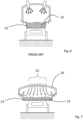
- figures 1-3 illustrate three plants produced according to the known art, in particular, figure 1 illustrates a traditional plant with a preheating tunnel without gas injectors; figure 2 illustrates a plant with air injectors arranged in the preheating tunnel according to the known art; figure 3 illustrates a plant with a heating and a preheating section, with burners, connected by a suction/evacuation section of the fumes.
- 1 indicates as a whole a plant for continuously feeding a metal charge of scrap 11 to an Electric Arc Furnace (EAF) 12 in which a bath of molten metal is present in the liquid state.
- EAF Electric Arc Furnace
- the flow 17 of fumes coming from the furnace 12 follows a substantially linear path, which tends to be aligned with the walls of the preheating tunnel, thus moving away from the metal charge 11. Also in the configuration of figure 2 , with the injectors of combustion air 19, the flow 17 does not undergo significant deviations, as the combustion air introduced by the injectors 10 is normally extremely limited, due to the infiltrations of cold air 18 which are present at the interface between the furnace 12 and the tunnel and which are almost always sufficient for completing the combustion of the fumes 17 coming from the furnace 12.
- a plant 1 of this type is described for example in patent US 5,183,143 .
- the plant 1 comprises at least one horizontal conveyor 13 suitable for continuously moving the metal charge of scrap 11 towards the electric melting furnace EAF 12, defining the respective continuous horizontal feeding line of the charge 11 to a charging area IV of the furnace itself 12.
- the horizontal conveyor 13 forms the base of a preheating tunnel 16 of the metal charge of scrap 11.
- the plant 1 is composed of a preheating section III which brings the metal charge of scrap 11 into the electric melting furnace EAF 12, of an evacuation section of the fumes II present in the plant 1, located, considering the movement direction of the scrap 11, upstream of said preheating section III, and of a section I which receives the metal charge of scrap 11 with a conventional receiving system of the scrap 11.
- the horizontal conveyor 13 conveys the metal charge of scrap 11 by oscillation and transfers it from the preheating section III to a movable terminal section, called "connecting car", which leads the scrap 11 into the electric melting furnace EAF 12.
- nozzles are present on the hood of the tunnel of the preheating section III (preheating tunnel 16), for the injection of gas 15.
- these are nozzles for the high-speed injection of gas 15.
- Said nozzles 15 are distributed so as to obtain a whirling turbulent motion inside the preheating tunnel 16 to improve the heat exchange between the off-gases 17 and metal charge of scrap 11.
- the nozzles 15 provided on the hood of the tunnel 16 of the preheating section III increase the turbulence of the off-gases 17 thus allowing the following to be obtained:
- the arrangement of the nozzles or "fluid-dynamic turbulators" 15 allows the so-called downwash portion of the field of motion to be concentrated on the central portion of the horizontal conveyor 13, where the maximum heat exchange is therefore obtained between the metal charge 11 and the gases/fumes 17 present in the preheating tunnel 16.
- the nozzles 15, and therefore the jets are distributed transversely on the hood of the preheating tunnel 16 in a non-uniform manner with a greater concentration on the top of the hood of the tunnel 16.
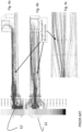
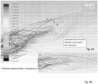
- the arrangement of the gas jets is therefore such as to obtain a well-defined whirling structure ( figures 9a, 9b ) inside the preheating tunnel 16, characterized by:
- This whirling structure of gases in the preheating tunnel 16 is commonly called a "horseshoe vortex" and is obtained, according to an embodiment of the present invention, by arranging the nozzles 15, and therefore the jets, over about 2/3 of the cross section of the preheating tunnel 16, leaving the two side walls, close to the side walls of the hood of said tunnel 16, free.
- the arrangement of the nozzles on the hood of the preheating tunnel 16 can vary in relation to the specific plant issues (see for example the embodiment solution shown in figure 8 ), maintaining anyway the requirement that the high-speed jets always intercept the central portion of the flow of off-gases 17, leaving the side portions free and thus favouring the establishment of an upward circulation of the gases and the formation of a horseshoe whirling motion in the entrainment flow.
- the high-speed jets that act as "fluid-dynamic turbulators" are not uniformly distributed longitudinally on the hood of the preheating tunnel 16, but according to "injection sections" adequately spaced apart from each other, so as to avoid fluid-dynamic interference phenomena; the distance between two adjacent injection sections should be 4-6 metres depending on the velocity of the gases passing through the preheating tunnel.
- the space between two adjacent injection sections is needed to allow the high-intensity flame produced by the section upstream to have time to develop before being pushed towards the charge by the injection section immediately downstream.
- the first injection section is positioned as close as possible to the electric melting furnace EAF 12.
- the first group of fast gas jets is located in proximity of the electric melting furnace 12, within a distance of 7-10 metres from the same.
- the invention provides for gas jets with velocities and/or flow-rates that increase among subsequent "gas injection sections".
- the number of injection sections varies from two to four, depending on the quantity of combustible gas produced by the melting process under consideration.
- the plurality of nozzles 15 forming the first injection section can be located above the connecting car ( first water-cooled hood ) whereas the nozzles 15 forming the other injection sections can be arranged at the beginning of each segment of the refractory section of the preheating tunnel 16 ( refractory lined hood ) .
- the gas injected is generally air but another gas can also be adopted and the gas used can also be preheated.
- Control means of the operating conditions of the nozzles 15 can be provided in each section.
- the jets released from the nozzles 15 are small and fast as they must be capable of providing both a mixing and deviation action on the stream of gas passing through the preheating tunnel 16, enabling the "downwash” motion of the hot gases 17 towards the metal charge 11, with a velocity sufficient for penetrating the interstices of the material (the so-called “impingement” effect, as visible in figure 5 , where the flow of hot gases 17 is pushed downwards towards the metal charge 11), thus improving the convective heat exchange.
- each single jet shall be designed in such a way that the set of jets has an impulse similar to the impulse of the main stream of fumes passing along the tunnel 16 from the furnace 12 to the suction plant.
- the first injection sections are designed to use lower flow-rates and velocities than the subsequent injection sections, due to the overall increasing flow-rate of the gas passing through the preheating tunnel.
- Each injection section can be managed, controlled and regulated independently of the others, depending on the process status and the characteristics of the charge 11 present in the preheating tunnel 16 and gases 17 leaving the furnace.
- the nozzles 15 are all the same and arranged on the top of the preheating tunnel 16 and their number basically depends on the width of the preheating tunnel 16 itself, considering an availability of about 2/3 of the central portion (where the "downwash" area is to be established) with a distance between each jet of about 450-500 mm.
- the top of the preheating tunnel 16 must be positioned at a distance of around 800-1,200 mm from the charge present in the conveyor (if the present invention is applied to an existing plant, this may require a redesigning of the preheating tunnel).
- the jets of air or other gas are mainly used for obtaining certain turbulence conditions inside the preheating tunnel 16.
- the overall injection capacity of the system described is almost always lower than the flow-rate of air necessary for completing the combustion of the process gases 17 coming from the furnace 12, as the primary objective of the system described is to stabilize the turbulence; the control of the supply of combustion air of the process gases inside the preheating tunnel 16 is basically delegated to the modulation of the suction depression and width of the gap between the entrance of the preheating tunnel and the furnace (that can never be completely eliminated from a plant-engineering point of view). In this way, the injection of air as turbulence generator is significantly decoupled by the supply of ambient air for completing the combustion of the process gases.
- the final objective of the present invention is to increase the combustion intensity of the process gases coming from the furnace and the heat exchange between them and the charge, thus increasing the overall energy efficiency of the melting process.
- the improved mixing and combustion of the process gases released from the furnace achieved with the present invention allows to obtain a better thermal destruction of the polluting substances (and related precursors) present therein.
- the present invention can also be applied to plants such as those described, for example, in the document WO2012007105 provided with a preheating tunnel and a heating tunnel of the metal charge of scrap.
- the scrap charge heating takes place through a turbulence created in the preheating tunnel 16, unlike what happens in the known plants in which the introduction of air is carried out according only to the requirements of the chemical combustion process, without any link to the control of the motion field inside the preheating tunnel.
- deflectors inside the preheating tunnel 16 can also be avoided.
- These deflectors have disadvantages as they cause a significant pressure drop in the suction of the fumes, they require cooling and frequent maintenance operations as they operate within a flow of very hot and dusty gases (this not only represents a plant complication and a potential risk of leakages, but also causes a useless loss of thermal energy by the gases), they are difficult to regulate and manage from a practical point of view as it is not easy to change the incidence angle, and finally, their effect is limited when the velocity and therefore flow-rates to be treated are low.
Landscapes
- Engineering & Computer Science (AREA)
- Mechanical Engineering (AREA)
- General Engineering & Computer Science (AREA)
- Chemical & Material Sciences (AREA)
- Manufacturing & Machinery (AREA)
- Materials Engineering (AREA)
- Metallurgy (AREA)
- Organic Chemistry (AREA)
- Environmental & Geological Engineering (AREA)
- Furnace Details (AREA)
Claims (14)
- Verfahren zum Vorwärmen einer Metallcharge (11), die kontinuierlich durch einen mit einem Horizontalförderer (13) versehenen Vorwärmtunnel (16) einem elektrischen Schmelzofen (12) zugeführt wird, wobei die Metallcharge (11) im Gegenstrom von den Abgasen oder dem Gas (17), die bzw. das den elektrischen Schmelzofen (12) verlassen, und von Gasstrahlen getroffen wird, die durch mehrere von an der Haube des mit Seitenwänden versehenen Tunnels (16) und der Haube angeordneten Düsen (15) ausgestoßen werden, die an der Haube des Tunnels (16) angeordnet sind, der mit Seitenwänden und der Haube versehen ist, dadurch gekennzeichnet, dass die Düsen (15) in Gruppen angeordnet sind, die in Längsrichtung des Tunnels voneinander beabstandet sind, und Gasstrahlen injizieren, die den durch den Vorwärmtunnel (16) laufenden Hauptgasstrom (17) durchdringen können, und die Düsen (15) gleichzeitig eine sogenannte "Hufeisenwirbel-"Struktur erzeugen , die aus einem absteigenden zentralen Gasstrom und aufsteigenden Strömen in der Nähe der Seitenwände des Vorwärmtunnels (16) besteht, die die notwendige Zirkulation der Gase ermöglichen, und ferner dadurch gekennzeichnet, dass die aus den Düsen (15) austretenden Gasstrahlen auf der Haube des Vorwärmtunnels (16) in einer ungleichmäßigen Weise quer verteilt sind, wobei eine größere Konzentration auf der Oberseite der Haube des Tunnels (16) vorliegt.
- Verfahren nach Anspruch 1, dadurch gekennzeichnet, dass die aus den Düsen (15) austretenden Gasstrahlen über etwa 2/3 des Querschnitts des Vorwärmtunnels (16) verteilt sind, wobei mindestens ein Teil der Seitenwände der Haube des Tunnels (16) frei bleibt.
- Das Verfahren gemäß einem oder mehreren der vorstehenden Ansprüche, dadurch gekennzeichnet, dass die Gasstrahlen in Längsrichtung entlang des Vorwärmtunnels (16) ungleichmäßig verteilt sind, wobei die Düsen (15) in Abschnitten, sogenannten "Gasinjektionsabschnitten", vorgesehen sind, die mit Längsabschnitten des Tunnels (16) ohne die Düsen (15) beabstandet sind, um Interferenzphänomene zu vermeiden.
- Verfahren nach einem oder mehreren der vorhergehenden Ansprüche, dadurch gekennzeichnet, dass die erste Gruppe von Gasstrahlen in der Nähe des elektrischen Schmelzofens (12) in einem Abstand von 7-10 Metern von diesem bereitgestellt wird.
- Das Verfahren gemäß einem oder mehreren der vorstehenden Ansprüche ist dadurch gekennzeichnet, dass die Gasstrahlen für eine Geschwindigkeit und/oder Durchflussrate ausgelegt sind, die zwischen aufeinanderfolgenden "Gaseinjektionsabschnitten" zunimmt.
- Das Verfahren gemäß einem oder mehreren der vorstehenden Ansprüche ist dadurch gekennzeichnet, dass der einzelne Strahl einer Düse (15) so dimensioniert ist, dass der Satz von Strahlen einen Impuls aufweist, der dem Impuls des Hauptstroms der Rauchgase ähnelt, die den Vorwärmtunnel (16) gemäß der folgenden Dimensionierungsbedingung durchlaufen:
 Wgas = Massstrom der Dämpfe im Tunnel (16) in einem bestimmten Injektionsabschnitt [kg/s]Wjet = Massstrom des Einzelstrahls im gleichen Injektionsabschnitt [kg/s]Vgas = Geschwindigkeit der Dämpfe im Tunnel (16) in Übereinstimmung mit demselben Injektionsabschnitt [m/s] Vjet = Geschwindigkeit des Einzelstrahls [m/s]Njets = Anzahl der Strahlen auf dem jeweiligen Injektionsabschnitt.
 - Anlage zur Durchführung eines Verfahrens zum Vorwärmen einer Metallcharge (11), die kontinuierlich einem elektrischen Schmelzofen (12) durch einen Vorwärmtunnel (16) zugeführt wird, der mit einem Horizontalförderer (13) versehen ist, wobei die Metallcharge (11) im Gegenstrom von den Abgasen oder dem Gas, die bzw. das den elektrischen Schmelzofen (12) verlässt, und von Gasstrahlen getroffen wird, die durch die mehreren von Düsen (15) ausgestoßen werden, die an der Haube des Tunnels (16) vorgesehen sind, der mit Seitenwänden und der Haube versehen ist, dadurch gekennzeichnet, dass mindestens zwei Gruppen von Düsen (15) an der Haube des Vorwärmtunnels (16) vorgesehen sind, die in Längsrichtung in Bezug auf den Tunnel voneinander beabstandet sind und Gasstrahlen injizieren, die den Hauptgasstrom (17) durchdringen können, der durch den Vorwärmtunnel (16) läuft, und die Düsen (15) erzeugen gleichzeitig eine "Hufeisenwirbel-", die aus einem absteigenden zentralen Gasstrom und aufsteigenden Strömen in der Nähe der Seitenwände des Vorwärmtunnels (16) besteht, die die notwendige Zirkulation der Gase ermöglichen, und ferner dadurch gekennzeichnet, dass die Düsen (15) quer und ungleichmäßig auf der Haube des Vorwärmtunnels (16) verteilt sind, wobei eine größere Konzentration auf der Oberseite der Haube des Tunnels (16) liegt.
- Anlage nach Anspruch 7, dadurch gekennzeichnet, dass die Düsen (15) über etwa 2/3 des Querschnitts des Vorwärmtunnels (16) verteilt sind, wobei zumindest ein Teil der Seitenwände der Haube des Tunnels (16) frei bleibt.
- Anlage nach einem oder mehreren der vorhergehenden Ansprüche von 7 bis 8, dadurch gekennzeichnet, dass die Düsen (15) in Längsrichtung und ungleichmäßig auf der Haube des Vorwärmtunnels (16) verteilt sind, wobei die Düsen (15) an Abschnitten entlang des Vorwärmtunnels (16), sogenannten "Gasinjektionsabschnitten", vorgesehen sind, die mit Längsabschnitten des Tunnels (16) ohne die Düsen (15) beabstandet sind, um Interferenzphänomene zu vermeiden.
- Anlage nach Anspruch 9, dadurch gekennzeichnet, dass es 2 bis 4 der "Gasinjektionsabschnitte" gibt, die in Längsrichtung des Tunnels in einem Abstand von etwa 4 bis 6 Metern voneinander angeordnet sind.
- Anlage nach Anspruch 9 oder 10, dadurch gekennzeichnet, dass der erste "Gasinjektionsabschnitt" in der Nähe des elektrischen Schmelzofens (12) in einem Abstand von 7 bis 10 Metern von diesem angeordnet ist.
- Die Anlage gemäß einem oder mehreren der vorhergehenden Ansprüche 9 bis 11, dadurch gekennzeichnet, dass drei "Gaseinjektionsabschnitte" entlang des Vorwärmtunnels (16) mit vier Düsen (15) pro Abschnitt vorgesehen sind.
- Die Anlage gemäß einem oder mehreren der vorhergehenden Ansprüche 8 bis 11, dadurch gekennzeichnet, dass die Düsen (15) für eine Geschwindigkeit und/oder Durchflussrate ausgelegt sind, die zwischen aufeinanderfolgenden "Gasinjektionsabschnitten" zunimmt.
- Die Anlage gemäß einem oder mehreren der vorstehenden Ansprüche ist dadurch gekennzeichnet, dass die Düsen (15) alle gleich und auf der Oberseite des Vorwärmtunnels (16) in einer von der Breite des Vorwärmtunnels (16) abhängigen Anzahl mit einem Abstand von etwa 450 bis500 mm zwischen den einzelnen Düsen angeordnet sind.
Applications Claiming Priority (2)
| Application Number | Priority Date | Filing Date | Title |
|---|---|---|---|
| IT201800007276 | 2018-07-18 | ||
| PCT/IB2019/055830 WO2020016702A1 (en) | 2018-07-18 | 2019-07-09 | Improved process and plant for preheating a metal charge fed in continuous to an electric melting furnace |
Publications (3)
| Publication Number | Publication Date |
|---|---|
| EP3824105A1 EP3824105A1 (de) | 2021-05-26 |
| EP3824105B1 true EP3824105B1 (de) | 2024-11-13 |
| EP3824105C0 EP3824105C0 (de) | 2024-11-13 |
Family
ID=65031599
Family Applications (1)
| Application Number | Title | Priority Date | Filing Date |
|---|---|---|---|
| EP19756254.9A Active EP3824105B1 (de) | 2018-07-18 | 2019-07-09 | Verbessertes verfahren und anlage zum vorwärmen einer einem elektroschmelzofen kontinuierlich zugeführten metallschmelze |
Country Status (5)
| Country | Link |
|---|---|
| US (2) | US11702713B2 (de) |
| EP (1) | EP3824105B1 (de) |
| CN (1) | CN112368401B (de) |
| ES (1) | ES2997484T3 (de) |
| WO (1) | WO2020016702A1 (de) |
Families Citing this family (5)
| Publication number | Priority date | Publication date | Assignee | Title |
|---|---|---|---|---|
| ES2997484T3 (en) * | 2018-07-18 | 2025-02-17 | Tenova Spa | Improved process and plant for preheating a metal charge fed in continuous to an electric melting furnace |
| IT202000000793A1 (it) * | 2020-01-17 | 2021-07-17 | Tenova Spa | Procedimento ed impianto perfezionati per preriscaldare una carica metallica alimentata in continuo ad un forno fusorio elettrico |
| IT202000022990A1 (it) * | 2020-09-29 | 2022-03-29 | Danieli Off Mecc | Apparato e metodo per l’alimentazione e il preriscaldo di una carica metallica in un forno di fusione |
| JP7490317B2 (ja) * | 2020-11-12 | 2024-05-27 | スチールプランテック株式会社 | 溶解設備 |
| IT202100030824A1 (it) * | 2021-12-07 | 2023-06-07 | Danieli Off Mecc | Forno elettrico ad arco per la fusione di materiale metallico ed impianto siderurgico comprendente detto forno elettrico ad arco |
Family Cites Families (11)
| Publication number | Priority date | Publication date | Assignee | Title |
|---|---|---|---|---|
| US5400358A (en) * | 1992-10-13 | 1995-03-21 | Consteel, S.A. | Continuous scrap preheating |
| CH690284A5 (it) * | 1995-05-24 | 2000-06-30 | Elti Srl | Procedimento di preriscaldo del rottame per postcombustione dei fumi e dispositivo per realizzare il procedimento. |
| CN1345381A (zh) * | 1997-08-22 | 2002-04-17 | 威廉·L·舍伍德 | 直接炼铁和钢 |
| US6273932B1 (en) * | 1998-05-19 | 2001-08-14 | William Lyon Sherwood | Continuous metal melting process |
| US6155333A (en) * | 1999-02-23 | 2000-12-05 | Techint Compagnia Tecnica Internazionale | Continuous electric steelmaking with charge preheating, melting, refining and casting |
| ITUD20030231A1 (it) * | 2003-11-27 | 2005-05-28 | Danieli Off Mecc | Procedimento di pre-riscaldo, trasformazione e fusione di una carica metallica e relativo impianto. |
| IT1401116B1 (it) * | 2010-07-14 | 2013-07-12 | Tenova Spa | Sistema di carica continua ad un forno fusorio di materiale metallico preriscaldato in forma continua, potenziata e combinata. |
| EP2546593B1 (de) * | 2011-07-12 | 2015-03-04 | SMS Concast Italia S.p.A. | Vorrichtung zur Übertragung von metallurgischem Material |
| WO2014126994A1 (en) * | 2013-02-14 | 2014-08-21 | Siemens Energy, Inc. | Gas turbine engine with an ambient air cooling arrangement having a pre-swirler |
| CN107460274B (zh) * | 2017-09-22 | 2023-09-12 | 中冶赛迪工程技术股份有限公司 | 一种水平连续加料预热装置及其强化预热方法 |
| ES2997484T3 (en) * | 2018-07-18 | 2025-02-17 | Tenova Spa | Improved process and plant for preheating a metal charge fed in continuous to an electric melting furnace |
-
2019
- 2019-07-09 ES ES19756254T patent/ES2997484T3/es active Active
- 2019-07-09 WO PCT/IB2019/055830 patent/WO2020016702A1/en not_active Ceased
- 2019-07-09 US US17/256,202 patent/US11702713B2/en active Active
- 2019-07-09 EP EP19756254.9A patent/EP3824105B1/de active Active
- 2019-07-09 CN CN201980044148.6A patent/CN112368401B/zh active Active
-
2023
- 2023-05-25 US US18/324,125 patent/US12195815B2/en active Active
Also Published As
| Publication number | Publication date |
|---|---|
| CN112368401B (zh) | 2022-11-01 |
| US11702713B2 (en) | 2023-07-18 |
| CN112368401A (zh) | 2021-02-12 |
| US12195815B2 (en) | 2025-01-14 |
| ES2997484T3 (en) | 2025-02-17 |
| WO2020016702A1 (en) | 2020-01-23 |
| EP3824105C0 (de) | 2024-11-13 |
| US20210262048A1 (en) | 2021-08-26 |
| US20230295756A1 (en) | 2023-09-21 |
| EP3824105A1 (de) | 2021-05-26 |
Similar Documents
| Publication | Publication Date | Title |
|---|---|---|
| US12195815B2 (en) | Process and plant for preheating a metal charge fed in continuous to an electric melting furnace | |
| US9677814B2 (en) | Continuous feeding system to a smelting furnace of pre-heated metal material, in continuous, potentiated and combined form | |
| US7384594B2 (en) | Method for the pyrometallurgical treatment of metals, metal melts and/or slags and injection device | |
| JP6557733B2 (ja) | 低速度燃料流のための燃焼方法 | |
| AU2003268825B2 (en) | Burner-lance and combustion method for heating surfaces susceptible to oxidation or reduction | |
| EP2748547B1 (de) | Vorrichtung und verfahren zur wärmebehandlung von klumpigem oder agglomeriertem material | |
| US12359873B2 (en) | Process and plant for preheating a metal charge fed in continuous to an electric melting furnace | |
| US20090126530A1 (en) | Method and equipment for treating process gas | |
| US11161764B2 (en) | Combustion method applied to melting materials such as glass in an end-fired furnace | |
| CN101754936B (zh) | 玻璃熔融装置及其操作方法 | |
| KR20140001926A (ko) | 확산형 연료 제트에 의한 연소 | |
| TWI817086B (zh) | 在ggr豎爐中燃燒含碳材料的方法 | |
| TR2023002299A2 (tr) | Mi̇neral i̇zolasyonun üreti̇lmesi̇ne yöneli̇k yöntem | |
| SU1567643A1 (ru) | Подова сталеплавильна печь |
Legal Events
| Date | Code | Title | Description |
|---|---|---|---|
| STAA | Information on the status of an ep patent application or granted ep patent |
Free format text: STATUS: UNKNOWN |
|
| STAA | Information on the status of an ep patent application or granted ep patent |
Free format text: STATUS: THE INTERNATIONAL PUBLICATION HAS BEEN MADE |
|
| PUAI | Public reference made under article 153(3) epc to a published international application that has entered the european phase |
Free format text: ORIGINAL CODE: 0009012 |
|
| STAA | Information on the status of an ep patent application or granted ep patent |
Free format text: STATUS: REQUEST FOR EXAMINATION WAS MADE |
|
| 17P | Request for examination filed |
Effective date: 20201203 |
|
| AK | Designated contracting states |
Kind code of ref document: A1 Designated state(s): AL AT BE BG CH CY CZ DE DK EE ES FI FR GB GR HR HU IE IS IT LI LT LU LV MC MK MT NL NO PL PT RO RS SE SI SK SM TR |
|
| DAV | Request for validation of the european patent (deleted) | ||
| DAX | Request for extension of the european patent (deleted) | ||
| GRAP | Despatch of communication of intention to grant a patent |
Free format text: ORIGINAL CODE: EPIDOSNIGR1 |
|
| GRAP | Despatch of communication of intention to grant a patent |
Free format text: ORIGINAL CODE: EPIDOSNIGR1 |
|
| STAA | Information on the status of an ep patent application or granted ep patent |
Free format text: STATUS: GRANT OF PATENT IS INTENDED |
|
| INTG | Intention to grant announced |
Effective date: 20240614 |
|
| GRAS | Grant fee paid |
Free format text: ORIGINAL CODE: EPIDOSNIGR3 |
|
| GRAA | (expected) grant |
Free format text: ORIGINAL CODE: 0009210 |
|
| STAA | Information on the status of an ep patent application or granted ep patent |
Free format text: STATUS: THE PATENT HAS BEEN GRANTED |
|
| AK | Designated contracting states |
Kind code of ref document: B1 Designated state(s): AL AT BE BG CH CY CZ DE DK EE ES FI FR GB GR HR HU IE IS IT LI LT LU LV MC MK MT NL NO PL PT RO RS SE SI SK SM TR |
|
| REG | Reference to a national code |
Ref country code: GB Ref legal event code: FG4D |
|
| REG | Reference to a national code |
Ref country code: CH Ref legal event code: EP |
|
| REG | Reference to a national code |
Ref country code: DE Ref legal event code: R096 Ref document number: 602019061952 Country of ref document: DE |
|
| REG | Reference to a national code |
Ref country code: IE Ref legal event code: FG4D |
|
| U01 | Request for unitary effect filed |
Effective date: 20241118 |
|
| U07 | Unitary effect registered |
Designated state(s): AT BE BG DE DK EE FI FR IT LT LU LV MT NL PT RO SE SI Effective date: 20241122 |
|
| REG | Reference to a national code |
Ref country code: ES Ref legal event code: FG2A Ref document number: 2997484 Country of ref document: ES Kind code of ref document: T3 Effective date: 20250217 |
|
| PG25 | Lapsed in a contracting state [announced via postgrant information from national office to epo] |
Ref country code: IS Free format text: LAPSE BECAUSE OF FAILURE TO SUBMIT A TRANSLATION OF THE DESCRIPTION OR TO PAY THE FEE WITHIN THE PRESCRIBED TIME-LIMIT Effective date: 20250313 Ref country code: HR Free format text: LAPSE BECAUSE OF FAILURE TO SUBMIT A TRANSLATION OF THE DESCRIPTION OR TO PAY THE FEE WITHIN THE PRESCRIBED TIME-LIMIT Effective date: 20241113 |
|
| PG25 | Lapsed in a contracting state [announced via postgrant information from national office to epo] |
Ref country code: NO Free format text: LAPSE BECAUSE OF FAILURE TO SUBMIT A TRANSLATION OF THE DESCRIPTION OR TO PAY THE FEE WITHIN THE PRESCRIBED TIME-LIMIT Effective date: 20250213 |
|
| PG25 | Lapsed in a contracting state [announced via postgrant information from national office to epo] |
Ref country code: GR Free format text: LAPSE BECAUSE OF FAILURE TO SUBMIT A TRANSLATION OF THE DESCRIPTION OR TO PAY THE FEE WITHIN THE PRESCRIBED TIME-LIMIT Effective date: 20250214 |
|
| PG25 | Lapsed in a contracting state [announced via postgrant information from national office to epo] |
Ref country code: PL Free format text: LAPSE BECAUSE OF FAILURE TO SUBMIT A TRANSLATION OF THE DESCRIPTION OR TO PAY THE FEE WITHIN THE PRESCRIBED TIME-LIMIT Effective date: 20241113 |
|
| PG25 | Lapsed in a contracting state [announced via postgrant information from national office to epo] |
Ref country code: RS Free format text: LAPSE BECAUSE OF FAILURE TO SUBMIT A TRANSLATION OF THE DESCRIPTION OR TO PAY THE FEE WITHIN THE PRESCRIBED TIME-LIMIT Effective date: 20250213 |
|
| PG25 | Lapsed in a contracting state [announced via postgrant information from national office to epo] |
Ref country code: SM Free format text: LAPSE BECAUSE OF FAILURE TO SUBMIT A TRANSLATION OF THE DESCRIPTION OR TO PAY THE FEE WITHIN THE PRESCRIBED TIME-LIMIT Effective date: 20241113 |
|
| PG25 | Lapsed in a contracting state [announced via postgrant information from national office to epo] |
Ref country code: SK Free format text: LAPSE BECAUSE OF FAILURE TO SUBMIT A TRANSLATION OF THE DESCRIPTION OR TO PAY THE FEE WITHIN THE PRESCRIBED TIME-LIMIT Effective date: 20241113 |
|
| PG25 | Lapsed in a contracting state [announced via postgrant information from national office to epo] |
Ref country code: CZ Free format text: LAPSE BECAUSE OF FAILURE TO SUBMIT A TRANSLATION OF THE DESCRIPTION OR TO PAY THE FEE WITHIN THE PRESCRIBED TIME-LIMIT Effective date: 20241113 |
|
| U20 | Renewal fee for the european patent with unitary effect paid |
Year of fee payment: 7 Effective date: 20250728 |
|
| PLBE | No opposition filed within time limit |
Free format text: ORIGINAL CODE: 0009261 |
|
| STAA | Information on the status of an ep patent application or granted ep patent |
Free format text: STATUS: NO OPPOSITION FILED WITHIN TIME LIMIT |
|
| PGFP | Annual fee paid to national office [announced via postgrant information from national office to epo] |
Ref country code: ES Payment date: 20250801 Year of fee payment: 7 |
|
| PGFP | Annual fee paid to national office [announced via postgrant information from national office to epo] |
Ref country code: TR Payment date: 20250708 Year of fee payment: 7 |
|
| PGFP | Annual fee paid to national office [announced via postgrant information from national office to epo] |
Ref country code: GB Payment date: 20250728 Year of fee payment: 7 |
|
| 26N | No opposition filed |
Effective date: 20250814 |
|
| REG | Reference to a national code |
Ref country code: CH Ref legal event code: H13 Free format text: ST27 STATUS EVENT CODE: U-0-0-H10-H13 (AS PROVIDED BY THE NATIONAL OFFICE) Effective date: 20260224 |