EP3824190B1 - Ventilateur et équipement conducteur pour un ventilateur - Google Patents
Ventilateur et équipement conducteur pour un ventilateur Download PDFInfo
- Publication number
- EP3824190B1 EP3824190B1 EP19734240.5A EP19734240A EP3824190B1 EP 3824190 B1 EP3824190 B1 EP 3824190B1 EP 19734240 A EP19734240 A EP 19734240A EP 3824190 B1 EP3824190 B1 EP 3824190B1
- Authority
- EP
- European Patent Office
- Prior art keywords
- guide device
- impeller
- guide
- housing
- fan
- Prior art date
- Legal status (The legal status is an assumption and is not a legal conclusion. Google has not performed a legal analysis and makes no representation as to the accuracy of the status listed.)
- Active
Links
Images


Classifications
-
- F—MECHANICAL ENGINEERING; LIGHTING; HEATING; WEAPONS; BLASTING
- F04—POSITIVE - DISPLACEMENT MACHINES FOR LIQUIDS; PUMPS FOR LIQUIDS OR ELASTIC FLUIDS
- F04D—NON-POSITIVE-DISPLACEMENT PUMPS
- F04D29/00—Details, component parts, or accessories
- F04D29/40—Casings; Connections of working fluid
- F04D29/42—Casings; Connections of working fluid for radial or helico-centrifugal pumps
- F04D29/4206—Casings; Connections of working fluid for radial or helico-centrifugal pumps especially adapted for elastic fluid pumps
- F04D29/4226—Fan casings
-
- F—MECHANICAL ENGINEERING; LIGHTING; HEATING; WEAPONS; BLASTING
- F04—POSITIVE - DISPLACEMENT MACHINES FOR LIQUIDS; PUMPS FOR LIQUIDS OR ELASTIC FLUIDS
- F04D—NON-POSITIVE-DISPLACEMENT PUMPS
- F04D29/00—Details, component parts, or accessories
- F04D29/40—Casings; Connections of working fluid
- F04D29/42—Casings; Connections of working fluid for radial or helico-centrifugal pumps
- F04D29/44—Fluid-guiding means, e.g. diffusers
- F04D29/441—Fluid-guiding means, e.g. diffusers especially adapted for elastic fluid pumps
- F04D29/444—Bladed diffusers
-
- F—MECHANICAL ENGINEERING; LIGHTING; HEATING; WEAPONS; BLASTING
- F04—POSITIVE - DISPLACEMENT MACHINES FOR LIQUIDS; PUMPS FOR LIQUIDS OR ELASTIC FLUIDS
- F04D—NON-POSITIVE-DISPLACEMENT PUMPS
- F04D29/00—Details, component parts, or accessories
- F04D29/40—Casings; Connections of working fluid
- F04D29/52—Casings; Connections of working fluid for axial pumps
- F04D29/522—Casings; Connections of working fluid for axial pumps especially adapted for elastic fluid pumps
-
- F—MECHANICAL ENGINEERING; LIGHTING; HEATING; WEAPONS; BLASTING
- F04—POSITIVE - DISPLACEMENT MACHINES FOR LIQUIDS; PUMPS FOR LIQUIDS OR ELASTIC FLUIDS
- F04D—NON-POSITIVE-DISPLACEMENT PUMPS
- F04D29/00—Details, component parts, or accessories
- F04D29/40—Casings; Connections of working fluid
- F04D29/52—Casings; Connections of working fluid for axial pumps
- F04D29/54—Fluid-guiding means, e.g. diffusers
- F04D29/541—Specially adapted for elastic fluid pumps
- F04D29/542—Bladed diffusers
-
- F—MECHANICAL ENGINEERING; LIGHTING; HEATING; WEAPONS; BLASTING
- F04—POSITIVE - DISPLACEMENT MACHINES FOR LIQUIDS; PUMPS FOR LIQUIDS OR ELASTIC FLUIDS
- F04D—NON-POSITIVE-DISPLACEMENT PUMPS
- F04D29/00—Details, component parts, or accessories
- F04D29/66—Combating cavitation, whirls, noise, vibration or the like; Balancing
- F04D29/661—Combating cavitation, whirls, noise, vibration or the like; Balancing especially adapted for elastic fluid pumps
-
- F—MECHANICAL ENGINEERING; LIGHTING; HEATING; WEAPONS; BLASTING
- F04—POSITIVE - DISPLACEMENT MACHINES FOR LIQUIDS; PUMPS FOR LIQUIDS OR ELASTIC FLUIDS
- F04D—NON-POSITIVE-DISPLACEMENT PUMPS
- F04D29/00—Details, component parts, or accessories
- F04D29/60—Mounting; Assembling; Disassembling
- F04D29/62—Mounting; Assembling; Disassembling of radial or helico-centrifugal pumps
- F04D29/624—Mounting; Assembling; Disassembling of radial or helico-centrifugal pumps especially adapted for elastic fluid pumps
- F04D29/626—Mounting or removal of fans
-
- F—MECHANICAL ENGINEERING; LIGHTING; HEATING; WEAPONS; BLASTING
- F04—POSITIVE - DISPLACEMENT MACHINES FOR LIQUIDS; PUMPS FOR LIQUIDS OR ELASTIC FLUIDS
- F04D—NON-POSITIVE-DISPLACEMENT PUMPS
- F04D29/00—Details, component parts, or accessories
- F04D29/60—Mounting; Assembling; Disassembling
- F04D29/64—Mounting; Assembling; Disassembling of axial pumps
- F04D29/644—Mounting; Assembling; Disassembling of axial pumps especially adapted for elastic fluid pumps
- F04D29/646—Mounting or removal of fans
-
- F—MECHANICAL ENGINEERING; LIGHTING; HEATING; WEAPONS; BLASTING
- F05—INDEXING SCHEMES RELATING TO ENGINES OR PUMPS IN VARIOUS SUBCLASSES OF CLASSES F01-F04
- F05D—INDEXING SCHEME FOR ASPECTS RELATING TO NON-POSITIVE-DISPLACEMENT MACHINES OR ENGINES, GAS-TURBINES OR JET-PROPULSION PLANTS
- F05D2250/00—Geometry
- F05D2250/50—Inlet or outlet
- F05D2250/52—Outlet
Definitions
- the present invention relates to a fan, in particular an axial, radial or diagonal fan, with a fan impeller and a downstream guide device in the housing! flow channel, wherein the guide device comprises guide vanes.
- Free-running diagonal or radial fans especially those with backward-curved blades, are well known in practice.
- There are no flow-carrying parts such as a spiral housing, guide vanes, diffusers or similar downstream of the impeller outlet.
- the flow exiting the impeller has high flow velocities.
- the dynamic pressures associated with these flow velocities are not used in free-running diagonal or radial fans. This means pressure and energy losses.
- such fans have too low pressure increases, too low air output and too low efficiency.
- these high flow velocities cause excessive noise emissions at the outlet.
- struts are often used to connect the motor fan wheel to a nozzle plate, which are usually very close to the impeller outlet.
- a radial fan is known in itself which has a round, bladed guide vane on the air outlet side for improved air circulation.
- This guide vane also serves as a suspension, but does not contribute to improving efficiency.
- the guide vane comprises a cover plate and a base plate, which each continue the corresponding cover plate or base plate of the impeller when assembled, as well as guide vanes which are partially arranged between the cover and base plate of the guide vane, but extend over their outer edges when viewed in the flow direction.
- the guide vane therefore causes a lot of noise.
- Another disadvantage of the known radial fan is that the guide device cover plate and the guide device base plate are not aligned when viewed in the flow direction. diverge greatly from each other, ie the flow cross-section widens significantly in the direction of flow. This leads to turbulence in the area of the guide device, increases the noise there and at the same time reduces the air output and thus the efficiency.
- the US 5 848 526 A , WO 85/02889 A1 , US 2018/106267 A1 and CN 107 588 046 A each design of fans.
- the document US 2018/106267 A1 discloses an axial fan with a fan impeller and a downstream guide device in the housing/flow channel, wherein the guide device comprises guide vanes which, viewed in the spanwise direction or radial direction, extend only over a part of the housing/flow channel, wherein two flow regions are formed downstream of the impeller, of which the inner flow region closer to the axis is delimited in the spanwise direction by the hub ring of the guide device and by an outer ring of the guide device, and wherein the outer flow region further away from the axis is delimited in the spanwise direction by the outer ring of the guide device and by the wall of the housing.
- the present invention is based on the task of designing and developing the generic fan in such a way that the problems occurring in the prior art are at least largely eliminated. While maintaining the lowest possible noise level, the static efficiency should be increased over a large area of the characteristic curve. In addition, the fan according to the invention should be different from competitive products.
- the guide device has a special structural design, namely the guide vanes, viewed in the span direction, extend only over a part of the flow area.
- the compact design of the guide vanes Apart from increasing the static efficiency or maintaining low noise levels, the compact design of the guide vanes, whose guide vanes essentially only extend over part of the span of the associated impeller, has a positive effect on tool and parts costs. Due to the comparatively smaller diameter of the guide vane in relation to a given impeller diameter, the tool size of the associated injection molding tools is smaller than usual.
- appropriately designed radial fans are particularly suitable for installation in narrow ducts with axial flow continuation.
- Fig.1 shows a perspective view of a guide device 1 serving as a guide device and a housing 2 of an embodiment of an axial-type fan according to the invention.
- the guide device 1 essentially consists of a hub ring 4, an outer ring 5 and guide vanes 3 extending between them.
- the guide device 1 is arranged, in the assembled state of the fan according to the invention, downstream of an impeller (not shown) within a housing 2, so that an air duct (outer flow area) 6 is created between the guide device 1 or its outer ring 5 and the wall of the housing 2, through which part of the air flowing off the impeller is guided.
- the inner flow area 7 is interspersed with guide vanes/guide elements 3 (in the example 13, preferably 3-19) which stabilize the swirling flow near the axis emerging from the impeller by reducing the swirl in the flow. This increases the efficiency.
- the hub ring 4 and the outer ring 5 run essentially over the entire circumference around the axis.
- the hub ring 4 surrounds an inner receiving area 8 in which, for example, the drive motor of the fan can be arranged.
- the receiving area 8 is not flowed through or advantageously only has a small air volume flow through it (0.1%-2% of the total air volume flow) in order to be able to transport away the waste heat produced by the motor.
- the outer flow area 6 has essentially no additional guide elements at least over a large area, seen in the span direction. As a result, little or no additional noise is caused in this area as a result of the interaction of the flow emerging from the impeller and the guide elements. This leads to a significantly reduced noise level in operation, since the flow speeds are high in this outer area 6 in particular.
- Flow stabilization in the outer flow area 6 by guide elements is not crucial for the efficiency of the fan. Overall, a fan is obtained that is low-noise, namely because guide elements are essentially missing in the outer flow area 6 or there are only a few guide elements there compared to the inner flow area 7.
- the fan according to the invention has a high efficiency due to the flow stabilization by the guide elements 3 in the inner flow area 7.
- Fig.2 shows, in axial plan view and seen from the downstream side, the guide device 1 and the housing 2 according to Fig.1
- the outer flow area 6, which in the exemplary embodiment has no guide elements, and the inner flow area 7 with the guide elements 3 can be clearly seen.
- no connection between the guide device 1 and the housing 2 is shown.
- such a connection is necessary in order to attach the guide device 1 to the housing 2. It can be realized using flat or rod material made of metal, or also using elements designed for optimal flow, which connect the guide device 1 to the housing 2.
- Such a necessary suspension, which must also run through the outer flow area 6, is not to be regarded as an actual guide element and does not change the statement that the outer flow area 6 essentially has no further guide elements.
- both the wall of the housing 2 and the hub ring 4 have a conical design towards the outflow end.
- An outer diffuser 10 is thus integrated in the housing 2.
- Both the inner flow area 7 and the outer flow area 6 are thus designed as diffusers with an expanding flow cross-section towards their outflow end. This is very advantageous for the static efficiency, especially in the case of axial fans.
- the outer ring 5 of the guide device 1 in the exemplary embodiment is designed in the shape of a cylinder jacket, aligned in the axial direction. This is particularly advantageous if the guide device is manufactured as a cast part, since the demolding of the guide elements 3, which are connected to the outer ring 5 at their outer end 12, is then greatly simplified. It is also conceivable to design a hub ring 4, to which the guide elements 3 are connected at their inner end 11, in the shape of a cylinder jacket for the same reason.
- fastening provisions for example fastening flanges, can advantageously be integrated or attached on both the inflow and outflow sides, which can serve to attach the fan to a higher-level system, for example an air-conditioning system.
- Fig.3 shows, in a side view and in section on a plane through the axis, the guide device 1 and the housing 2 of Fig. 1 and 2 .
- the cross-section shows the outer flow area 6 without guide elements, the inner flow area 7 with the guide elements 3 and the receiving area 8 within the hub ring 4.
- the impeller (not shown) is arranged in the assembled state in area 29 upstream of the guide device 1.
- the air flows approximately from left to right in this view, first through the inlet nozzle 9 integrated in the housing 2, then through the impeller (not shown) before it is divided into the outer flow area 6 and the inner flow area 7, in which the flow is stabilized (especially in the inner flow area 7) and in which kinetic energy of the flow is converted into pressure energy.
- the receiving area 8 within the hub ring 4 there is a provision or mechanism 18 for attaching a motor.
- the guide device 1 can be designed to be load-bearing. This means that it is stably connected to the housing in the area of its outer ring 5 (with struts, flat material or aerodynamically optimized sheet metal or plastic elements) and the motor together with the impeller is held on a motor fastening device 18 in the inner area 8 of the guide device 1.
- the guide device 1 can be designed to be non-load-bearing, which means that the motor is fastened to a housing 2 via a support device (in particular consisting of rod or flat material), and a non-load-bearing guide device 1 is then fastened to the motor or the associated support device, or fastened to the housing 2 by means of a separate support device.
- a support device in particular consisting of rod or flat material
- parts of the support device must traverse the outer flow area 6, which should not change the statement that the outer flow area 6 is essentially free of guide elements over a large part of its span.
- the guide elements 3 in the embodiment have a special and advantageous design.
- they consist of an inclined part 16 adapted to the inflow direction, and in the area of the outflow, an axially aligned part 15 and a transition area 17 located between the parts 15 and 16.
- the transition area 17 is simply designed as a kink.
- An inflow that is as shock-free as possible in the area of the leading edge 13 of a guide vane 3 is advantageous for achieving a high level of efficiency and low noise generation.
- the inclined part 16 of the guide vane 3 serves this purpose, which is aligned approximately parallel to the direction of the swirling inflow coming from the impeller (see also Fig.4 ).
- part 15 of the guide vanes 3, which is located in areas of the conical hub ring, is designed as an axially aligned part. This is also the case in Fig.2 This can be clearly seen in areas where the inner end 11 of a guide element 3 borders on the conical part of the hub ring 4.
- the hub ring 4 and guide elements 3 together with the outer ring 5 can be demolded parallel to the axial direction without undercuts, if the guide device 1 is a cast part, preferably made by plastic injection molding.
- the hub ring 4 in the area of the inclined part 16 of the guide vane 3 is not conical, but rather cylindrical in shape.
- the hub ring 4 is therefore more cylindrical in shape in a first area and more conical in a second area.
- Fig. 3a shows in a side view and in section on a plane through the axis the guide device 1 and the housing 2 of Fig. 1 to 3 with built-in impeller 19 of axial design and the schematically shown motor 34, which consists in particular of a rotor 35 and a stator 36.
- the impeller consists of a hub ring 38, to which advantageously 3-13 impeller blades 22 are attached.
- the impeller 19 runs inside the housing 2 so that there is only a small gap between the impeller blades 22 and the housing 2.
- the impeller 19 is attached at its hub ring 38 to the rotor 35 of the motor 34, which drives the impeller 19.
- the guide device 1 is attached to the stator 36 of the motor 34.
- the guide device 1 is firmly connected to the housing 2 at its outer ring 5 by means of suspension elements (not shown); in non-load-bearing embodiments, the motor 34 is firmly connected to the housing 2 at its stator 36 by means of suspension elements (not shown).
- the outer contour of the impeller hub 38 advantageously has the same or a similar outer diameter as the outer contour of the hub ring 4 of the guide device 1, at least at the mutually facing ends. This provides an essentially continuous flow-limiting contour towards the inner area close to the axis, which is very advantageous for high efficiency and low noise generation.
- a hub cap 37 is attached to the inflow side of the hub ring 38 of the impeller 19, which can, for example, have approximately the outer contour of half an ellipsoid, and which forms a continuous, inner flow-limiting contour with the hub ring 38.
- the motor 34 is an external rotor motor which is mounted within the hub rings 38 and 4 (or also in the receiving area 8 within the hub ring 4), which means a space-saving solution and enables a compact design of the fan.
- a slight air volume flow is generated within the hub rings 38 and 4 (or also in the receiving area 8 within the hub ring 4) by suitable measures (openings, bores, slots or similar) in order to be able to better dissipate the waste heat of the motor 34.
- Fig.4 shows, in a side view and in section on a plane parallel to the axis, the guide device 1 and the housing 2 according to Fig. 1 to 3
- the cutting plane does not pass through the axis, but is at a distance from it that is in the area of the mean radius of a guide vane 3.
- some guide vanes 3 appear to be cut, and their already Fig.3
- the structure described is even clearer.
- the guide vanes 3 have an inflow edge 13 on the inflow side and a corresponding outflow edge 14 on the outflow side.
- the inclined part 16 of a guide vane 3 is aligned approximately parallel to the flow direction of the swirling flow arriving from the impeller, particularly in the area of the inflow edge 13.
- An axially aligned part 15 of the guide vane is formed towards the outflow edge 14.
- This design significantly facilitates the demolding of a guide device 1 with a conical hub ring 4 and/or conical outer ring 5 from a casting tool.
- the transition 17 between the parts 15 and 16 of a guide vane 3 is designed as a kink in the exemplary embodiment, but can also be designed, for example, as a rounded area with a continuous tangent or a continuous curvature.
- the angle that the inclined part 16 of a guide wing 3 has approximately at the inflow edge 13 to a parallel to the axis is advantageously in a range between 20° and 50°.
- the inclined part 16 of a guide wing 3, as in the embodiment advantageously has the profile of an airfoil in cross section.
- Fig.5 shows, in perspective view from the inflow side, the guide device 1 and the housing 2 according to Fig. 1 to 4 .
- the air flows through the inlet nozzle 9 into the housing 2.
- the flow channel delimited by the wall of the housing 2 or the nozzle 9 tapers in the area of the nozzle 9 to a narrowest cross-section when air flows through, whereby the air is accelerated.
- An impeller is arranged in the cross-section of the housing 2.
- the embodiment is particularly suitable for an impeller of axial design.
- a mounting flange 18 with holes for attaching a motor is clearly visible.
- the guide device 1 is advantageously manufactured in one piece using a plastic injection molding process.
- a significantly smaller injection molding tool is required, which saves tool costs and production costs due to the smaller outer diameter of the guide device 1.
- the housing 2 itself, including the integrated inlet nozzle 9 and integrated outer diffuser 10, can advantageously be manufactured inexpensively from sheet metal. In this case, production from one or more sheet metal parts is conceivable, which are then screwed, welded, riveted or otherwise connected.
- Fig.6 is, in axial plan view, seen from the inflow side, the guide device and the housing according to Fig. 1 to 5 shown.
- the outer flow area 6 and the inner flow area 7 can be clearly seen, which are separated from each other by the outer ring 5 of the guide device 1.
- the outer ring 5 is axially aligned.
- the mounting flange 18 for mounting a motor is arranged in the receiving area 8. In this illustration, only the inclined part 16 of the guide vanes 3 up to the transition area 17 can be seen in this embodiment.
- the guide vanes 3 are designed in a sickle shape, i.e. in this view, the inflow edges 13 of the guide vanes 7 are curved.
- the ends of the inflow edges 13 located on the outer ring 5 are offset in the circumferential direction against the direction of rotation of the impeller compared to the ends of the inflow edges 13 located on the hub ring 4.
- the direction of rotation of the impeller (not shown) is clockwise with respect to the given viewing orientation.
- Fig.7 shows, in perspective view, seen from the downstream side, a guide device 1 of a further embodiment of a fan of radial or diagonal design.
- the guide device 1 has 4 guide elements 3, which extend radially in a curved course from a hub ring 4 to an outer ring 5.
- a fastening flange 18 for fastening a motor is attached within the hub ring 4.
- the guide elements 3 are designed to be aligned in the axial direction and can advantageously be made of sheet metal.
- the outer ring 5 in the exemplary embodiment has the geometry of a rotating body around the axis.
- Fig.8 shows, in perspective view, seen from the downstream side, the guide device 1 according to Fig.7 with associated impeller 19 of radial design.
- the radial impeller 19 in the exemplary embodiment consists essentially of a cover disk 20, a base disk 21 and blades 22 extending between them.
- the motor is not shown. It can be attached on the stator side to the fastening flange 18 within the hub ring 4 of the guide device and on the rotor side to the corresponding fastening device 30 on the impeller 19.
- the guide device 1 is arranged downstream of the flow outlet 31 from the radial impeller 19, but does not extend over the entire span at the flow outlet 31 from the impeller 19, only over an area closer to the base disk 21.
- the contour of the outer ring 5 of the guide device 1 in the exemplary embodiment causes the air emerging radially from the radial impeller 19 to be deflected more in the axial direction, in a direction parallel to the axis.
- Fig.9 shows, in axial plan view from the downstream side, the guide device according to Fig.7 .
- the guide elements 3 of which only the trailing edge 14 can be seen, are aligned in the axial direction.
- a fastening device 18 is attached in the receiving area 8 inside the hub ring 4.
- the guide elements 3 are curved in the viewing plane, with the curvature starting from the inside of the hub ring 4 outwards to the outer ring 5 running against the direction of rotation of an impeller.
- the direction of rotation of an impeller in the embodiment shown in this illustration is clockwise.
- the angle of inclination of the guide elements 3 to the corresponding radial direction advantageously has the maximum value on the outer ring 5, which is greater than 20°, advantageously greater than 35°.
- Fig.10 shows, in axial plan view from the downstream side, the guide device 1 and the impeller 19 according to Fig.8 .
- Fig.9 The outer edge 24 of the base disk 21 of the impeller 19 has a smaller outer diameter than the inflow-side edge 23 of the outer ring 5 of the guide device 1. This makes it possible to slide the guide device 1 over the base disk 21 of the impeller to facilitate assembly of the fan.
- Fig. 11 shows, in a side view and in section on a plane through the axle, the guide device 1 and the impeller 19 according to Fig.8 and 10 .
- the contour of the outer ring 5 of the guide device 1, which is connected to the radially outer ends 12 of the guide elements 3, can be clearly seen.
- This is strongly curved towards its inflow end 23, so that at the inflow end 23 of the outer ring 5 it has no or only a small angle of attack compared to the flow, which flows out of the impeller 19 in a more radial direction. As it runs, it deflects this flow in an axial direction. At the downstream edge 28, it therefore runs approximately parallel to the axis.
- the outer ring 5 alone (without guide elements 3) according to this embodiment can be demolded from a casting tool without undercuts.
- the guide elements 3, which in the embodiment are advantageously made of sheet metal, can then be attached to the outer ring 5 of the guide device 1, for example by screwing or clipping.
- the guide device 1 with the outer ring 5 extends, viewed in the span direction of the impeller 19, only over a part of the flow outlet 31 from the impeller 19.
- the inflow-side edge 23 of the outer ring 5 of the guide device 1 is located approximately at an axial position in the range of 50%-70% of the width measured from the cover disk 20.
- the guide elements 3 in the embodiment have rather small axial
- the axial extension of the guide elements 3 is approximately 20%-60% of the axial width of the outlet 31 of the impeller 19, thereby achieving an axially compact design.
- Fig. 12 shows, in a side view and in section on a plane through the axle, the guide device 1 and the impeller 19 according to Fig.8 and 10 to 11 , with an inlet nozzle 9 built into a housing 2 which is designed as a pressure-side air duct. In this housing 2 the air is guided further after the impeller 19 in a direction approximately parallel to the axis.
- the guide device 1 shown can be used particularly advantageously in this configuration.
- the air exiting the impeller 19 at the outlet 31 is divided into two flow areas, firstly the outer flow area 6 and the other hand the inner flow area 7.
- the outer ring 5 of the guide device 1 represents the separation between the two flow areas 6 and 7.
- the outer flow area 6 has essentially no further guide elements over a large part of its span.
- the inner flow area 5 has the guide elements 3, 4 in the exemplary embodiment, which stabilize the swirling air flow exiting the impeller 19 in the flow area 7 closer to the axis by reducing the swirl.
- the guide device 1 must be attached to the housing 2 by a suspension (not shown). This can advantageously be achieved by extending one, several or all of the guide elements 3 to the wall of the housing 2.
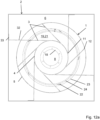
- Fig. 12a shows, in axial plan view from the downstream side, a housing 2, a guide device 1 and an impeller 19 of another embodiment of a fan.
- the outer edge 24 of the base plate 21 of the impeller 19 lies within the inflow-side edge 23 of the outer ring 5 of the guide device 1. This allows the guide device 1 to be pushed over the base plate 21.
- the guide elements 3 are not curved. This significantly simplifies the manufacture of the guide elements 3 from sheet metal. In order to achieve good flow properties, high efficiency and low noise levels, the guide elements 3 are twisted or angled relative to the radial direction.
- the angle of twist to the local radial is approximately 30°, advantageously 15°-45°.
- the guide elements 3 in the exemplary embodiment meet the hub ring 4 at an acute angle.
- the hub ring 4 and the guide elements 3 are advantageously made from sheet metal and welded and screwed together.
- the outer ring 5 is designed as a rotational body (similar to the outer ring according to. Fig.7-12 ) is advantageously manufactured as a cast part, in particular as a plastic injection-molded part.
- the connection of the guide elements 3 at their outer end 12 to the outer ring 5 is advantageously carried out by clipping, screwing, riveting or the like. Appropriate provisions can be present on the injection-molded part.
- the suspension of the guide device 1 and thus also of the motor and the impeller 19 on the housing 2 is carried out by means of the suspension 32, in which the function of some guide elements is integrated.
- the geometry of the suspension 32 radially inside the outer ring 5 of the guide device 1 corresponds approximately to the geometry of the other guide elements 3.
- the suspension 32 is advantageously made of sheet metal and is attached to the housing 2 with the fastening 33, advantageously by screws or rivets. This functional integration leads to particularly cost-effective production.
- the suspension 32 with the integrated guide element function also traverses the outer flow area 6. Since additional guide elements 3 are present in the inner flow area 7, the embodiment also applies that the outer flow area 6 has essentially no guide elements, at least in comparison to the inner flow area 7.
- suspension-specific elements run in an outer flow area 6. This is little compared to the inner flow area 7, since the outer flow area 6 additionally has a much larger cross-sectional area than the inner flow area 7 and thus the distance between adjacent suspensions 32, seen in the circumferential direction, is large compared to the distance between adjacent guide elements 3 in the inner flow area 7, taking into account the integrated suspensions / guide elements 32.
- Fig. 13 shows, in perspective view from the downstream side, a guide device 1 and a housing 2 of another embodiment of an axial-type fan.
- Suspension struts 25 are shown schematically, which in this load-bearing embodiment of the guide device 1 provide the connection between the guide device 1 and the housing 2.
- the suspension struts 25 can be made of sheet metal, rod material or cast iron, and can then advantageously be provided with a shape that is optimized for aerodynamics. In the case of suspension struts 25 made of flat material, it is also conceivable that they are not axially aligned, but are attached at an angle to the axial direction that is favorable for aerodynamics.
- the outer flow area 6, at least in comparison to the inner flow area 7, is to be regarded as essentially free of guide elements.
- the suspension struts 25 can be screwed, riveted, welded or the like to the housing 2 and/or outer ring 5 of the guide device 1.
- a one-piece, monolithic, integral production of the entirety of the housing 2 and the guide device 1 with suspension struts 25 as a cast part is also conceivable.
- the guide vanes 3 have an inflow-side inclined part 16, an outflow-side axially aligned part 15 and a transition region 17 in order to combine the realization of flow-optimized inflow angles with easy demoldability of the guide device 1, in particular if the hub ring 4 and/or outer ring 5 of the guide device 1 have a conical shape at least in some areas.
- the transition region 17 is designed here as a rounded region that connects the inclined part 16 and the axially aligned part 15 in a tangentially continuous manner.
- Fig. 14 shows, in axial plan view from the inflow side, the guide device 1 and the housing 2 according to Fig. 13 .
- the guide device 1 has 11 guide elements 3.
- the 4 suspension struts 25 are arranged slightly unevenly distributed over the circumference, since in their circumferential position they are always arranged approximately between adjacent guide elements 3.
- the outer ring 5 of the guide device 1 is not designed as a rotating body. However, it still runs over the entire circumference and connects the guide elements 3 to one another at their outer end 12.
- the outer ring 5 is not designed to be axially aligned, but is essentially conical with specially designed demolding areas 26 near the guide vanes 3, which have the function of enabling or facilitating the demolding of the guide device 3 from a casting tool. In fact, in the demolding areas 26, in which it is necessary for a clear demolding in the axial direction, the outer ring 5 is designed to be locally axially aligned.
- tangent-continuous transition areas are formed in an area between adjacent guide vanes 3, and step-like transition areas are formed in the area of the guide vanes 3, with the shape of the steps there corresponding approximately to the continuation of the contour of the guide vanes 3.
- an area of the guide vanes 3 near their outer end 12 connects an axially aligned part 26 of the outer ring 5 with a conical part 27 of the outer ring 5.
- Fig. 13 The design of the guide elements with an inclined part 16 and an axially aligned part 15, as already described, ensures that the circumferential extension of a guide vane 3, in particular near the outer end 12, is very low. This minimizes the circumferential area in which the outer ring 5 has to be designed in the form of a demolding area 26 in the shape of a cylinder jacket in order to achieve demolding without undercuts, which is advantageous in particular for the efficiency.
- Fig. 14 the outer flow area 6 with few guide elements and the inner flow area 7 with many guide elements can be clearly seen.
- the area inside the hub ring 4 is not shown in detail here, but can be similar to the embodiments according to Fig. 1-12 , 12a be designed.
- Fig. 15 shows, in a side view and in section on a plane through the axis, the guide device 1 and the housing 2 according to Fig. 13 and 14
- this outer ring 5 is designed in such a way that the radius (distance from the axis) of the contour decreases in the flow direction.
- the hub ring 4 is designed to be axially aligned with a cylindrical shell shape.
- the inner flow area 7 is thus designed as a confuser.
- This design leads to additional stabilization of the swirling flow near the axis flowing out of the impeller (not shown), thereby achieving a further increase in efficiency. Furthermore, a particularly advantageous long-throw behavior of the air exiting from the flow areas 6 and 7 on the outflow side is achieved, i.e. the air jet remains compact over a long distance and has high air velocities over a long distance in the area of the imaginary continuation of the axis, which is advantageous for some applications of a fan.
- the type of conical design of the outer ring 5 of the guide device 1 also influences the cross-sectional profile of the outer flow area 6.
- This flow area 6 therefore takes on the character of a diffuser to a greater extent.
- the conical opening angle of the outer diffuser wall 10 integrated in the housing 2 must therefore be selected to be smaller than in the case of a cylinder jacket-like design of the outer ring 5. This makes the outer diameter at the downstream outlet from the housing 10 lower, which enables a more compact design.
- the formation of the diffuser 10 on the housing 2 can even be dispensed with, i.e. the housing 2 can be designed with an axially aligned cylinder jacket contour towards its outflow end, which simplifies the manufacture of the housing 2.
- Fig. 16 is shown in an axial plan view, seen from the downstream side, of a housing 2, a guide device 1 and an impeller 19 of a further embodiment of a fan.
- the guide device 1 is made essentially of sheet metal and is therefore advantageously constructed essentially from flat partial areas. In particular, there are no flat areas which have a significant curvature.
- the impeller 19 shown, of which the base plate 21, cover plate 20 and the blades 19 can be partially seen, is a radial impeller.
- the housing 2 is a flow channel with a square cross-section in which the air is passed on in the axial direction, in the view towards the viewer, after exiting the impeller 19 or the guide device 1.
- the outer contour of the guide element 1 or its outer ring 5 also has a square contour in this direction of view. It is rotationally symmetrical with a division into four, but here it is not a rotating body. This makes it easier to construct the guide element 1 from flat areas, which makes it much easier to manufacture the guide element 1 from sheet metal.
- a square outer contour of the guide element 1 is particularly suitable in terms of flow technology if the housing 2 also has a square cross-section.
- the outer flow area 6 has a largely constant width, defined by the distance between the outer ring 5 of the guide device 1 and the wall of the housing 2, which form the inner and outer edges of the outer flow area 6.
- the hub ring 4 also has the aerodynamically advantageous square contour parallel to the contour of the housing 2 or the contour of the outer ring 5.
- a fastening area 18 for the stator side of a motor (not shown) is provided on the hub ring 4.
- a fastening device 30 for the rotor side of the motor can be seen on the base plate 21 of the impeller 19.
- the outer ring 5 is also essentially made up of flat areas 5a, 5b, 5c.
- the flat area 5c which runs perpendicular to the fan axis, is assigned to the circular inflow-side edge 23. This provides a favorable inflow angle compared to the flow exiting the impeller 19 in an approximately radial direction.
- the flat areas 5a which lie parallel to the fan axis in the design area and thus parallel to the air conveying direction in the housing or flow channel 2, are assigned to the outflow-side edge 28.
- Flat transition areas 5b are also formed between the flat areas 5c and 5a, which promote the low-loss deflection of the air exiting radially from the impeller 19 in the axial direction.
- the outer side length of the guide device 1 in this embodiment is, as seen in this view, approximately 1.15 times the outer diameter at the outer edge 24 of the base plate 21 of the impeller 19, advantageously it is 1.1-1.2 times.
- Such a ratio is particularly suitable for tight installation conditions, i.e. when the side length of the housing 2, as seen in cross section, is less than 1.6 or 1.5 times the average diameter of the trailing edges of the blades 22 of the impeller 19 with respect to the fan axis.
- Fig. 17 the housing 2, the guide device 1 and the impeller 19 according to the embodiment according to Fig. 16 shown in a side view and in section on a plane through the axis.
- the flat areas of the outer ring 5 of the guide device 1 are clearly visible in the section.
- the inflow-side edge 23 of the outer ring 5 of the guide device 1 is located closer to the base plate 21 than to the cover plate 20, viewed in the span direction of the impeller 19, approximately at 75% (preferably 60%-80%) of the span, viewed from the cover plate.
- This is also advantageous for a tight installation situation of the impeller 19 with respect to the housing 2, i.e. when the side length of the housing 2, viewed in cross section, is less than 1.6 or 1.5 times the average diameter of the trailing edges of the blades 22 of the impeller 19 with respect to the fan axis.
- the control device 1 of the Fig. 17 can be easily manufactured from sheet metal, as it is made up of flat areas. To do this, one or more sheet metal parts are trimmed or punched out, folded over if necessary and joined where necessary, for example by welding, tacking, toxing, riveting or screwing.
- the guide device 1 can be designed to be load-bearing or non-load-bearing. Necessary suspension elements which attach the impeller 19 and the guide device 1 to the housing 2 are not shown.
- Fig. 18 shows, in axial plan view, seen from the downstream side, a housing 2, a guide device 1 and an impeller 19 of another embodiment of a fan.
- the fan is constructed very similarly to the embodiment according to Fig. 16 and 17 , however, the guide elements 3 also have inclined areas 16 which are connected to the axially aligned parts 15 on the inflow side. This allows the inflow losses of the guide device 1 to be reduced by a more suitable inflow angle of the swirling flow emerging from the impeller 19.
- the inclined parts 16 are also designed as flat areas. For the rest, please refer to the explanations on Fig. 16 and 17 referred to.
Landscapes
- Engineering & Computer Science (AREA)
- Mechanical Engineering (AREA)
- General Engineering & Computer Science (AREA)
- Structures Of Non-Positive Displacement Pumps (AREA)
Claims (14)
- Ventilateur, plus particulièrement ventilateur axial, radial ou diagonal, avec une turbine de ventilateur (22) et un dispositif de correction (1), dans lequel le dispositif de correction comprend des ailettes de correction (3) qui s'étendent, vues dans la direction de l'envergure ou dans la direction radiale, uniquement sur une partie du boîtier/canal d'écoulement (6),dans lequel le dispositif de correction présente une structure agissant comme un diffuseur, avec une section transversale d'écoulement s'élargissant progressivement, vue dans la direction d'écoulement,et dans lequel, en aval de la turbine, se trouvent deux parties d'écoulement, la partie d'écoulement interne la plus proche de l'axe étant limitée, vue dans la direction de l'envergure, par la bague de moyeu du dispositif de correction et par une bague externe (5) du dispositif de correction et dans lequel la partie d'écoulement externe la plus éloignée de l'axe est limitée, vue dans la direction de l'envergure, par la bague externe du dispositif de guidage et par la paroi du boîtier (2).
- Ventilateur selon la revendication 1, caractérisé en ce que les ailettes de correction s'étendant approximativement sur la moitié de l'ensemble du boîtier/canal d'écoulement radial de l'envergure.
- Ventilateur selon la revendication 1 ou 2, caractérisé en ce que le dispositif de correction présente un diamètre inférieur à celui de la turbine de ventilateur.
- Ventilateur selon l'une des revendications 1 à 3, caractérisé en ce que la bague externe se présente globalement sous la forme d'un corps rotatif ou est réalisée et disposée avec une symétrie de rotation par rapport à l'axe du ventilateur.
- Ventilateur selon la revendication 4, caractérisé en ce que la bague externe est conçu comme un élément se rétrécissant de manière conique du côté d'entrée vers le côté de sortie, de sorte que la partie proche des ailettes de correction est conçue pour le démoulage sans contre-dépouille hors d'un outil de coulée, vue dans la direction axiale.
- Ventilateur selon la revendication 4 ou 5, caractérisé en ce que le contour de la bague externe est incurvé de plus en plus fortement de son extrémité côté sortie vers l'extrémité côté entrée, de façon à ne présenter, par rapport à un écoulement, de préférence radial, hors de la turbine, aucun angle ou à présenter un faible angle d'attaque et dévie cet écoulement de préférence dans la direction axiale ou parallèlement à l'axe du ventilateur.
- Ventilateur selon l'une des revendications 1 à 6, caractérisé en ce que les ailettes de correction présentent, dans l'extension radiale, une extension incurvée, de préférence en forme de faucille, plus particulièrement avec une courbure opposée au sens de rotation de la turbine correspondante, dans lequel
les ailettes de correction présentent, au moins dans une partie externe radialement, un angle d'inclinaison supérieur à 30°, de préférence supérieur à 45°, par rapport à la ligne radiale. - Ventilateur selon la revendication 7, caractérisé en ce que les ailettes de correction présentent une première partie côté entrée et une deuxième partie côté sortie, dans lequel la partie côté entrée peut présenter la section transversale profilée d'une ailette porteuse avec un angle d'entrée par rapport à l'axe du ventilateur sur l'arête avant de la ligne du squelette de l'ordre de 20° à 50°, et/ou dans lequel la partie côté sortie peut s'étendre parallèlement à l'axe du ventilateur et/ou dans lequel la transition entre les parties peut être réalisée de manière tangentielle ou non, sous la forme d'un coude.
- Ventilateur selon l'une des revendications 1 à 8, caractérisé en ce que le dispositif de correction comprend ou forme au moins une partie d'une suspension, dans lequel le dispositif de correction peut présenter, sur le contour externe, des moyens pour sa propre suspension.
- Ventilateur selon la revendication 9, caractérisé en ce que, sur le côté entrée du contour interne du dispositif de correction, est prévue une bride pour la fixation du moteur, dans lequel le moteur est suspendu, de préférence conjointement avec la turbine de ventilateur correspondante par l'intermédiaire du dispositif de correction sur un boîtier/canal d'écoulement.
- Ventilateur selon la revendication 9 ou 10, caractérisé en ce que, entre la bague externe et une paroi du boîtier/canal d'écoulement, s'étendent des entretoises de suspension constituées de préférence d'un matériau plat et/ou qui peuvent être incurvées et/ou disposées de manière semblable aux ailettes de correction.
- Ventilateur selon la revendication 9 ou 10, caractérisé en ce que, pour la fixation du dispositif de correction, une ou plusieurs ailettes de correction sont prolongées vers l'extérieur jusqu'à une paroi du canal conduisant l'air ou un boîtier externe, de façon à réaliser des moyens de fixation intégraux.
- Ventilateur selon l'une des revendications 1 à 12, caractérisé en ce que le dispositif de correction est constitué d'une tôle et est constitué globalement de parties planes.
- Ventilateur selon l'une des revendications 1 à 13, caractérisé en ce que le bord côté entrée de la bague externe du dispositif de correction est disposé, dans la direction d'écoulement, après les ailettes de la turbine, dans lequel sa position se trouve, vue dans la direction de l'envergure, entre les deux extrémités des ailettes de la turbine, de préférence approximativement au milieu ou dans une zone de 20 - 80 % de l'extension de l'envergure des ailettes de la turbine.
Priority Applications (1)
| Application Number | Priority Date | Filing Date | Title |
|---|---|---|---|
| SI201930856T SI3824190T1 (sl) | 2018-07-16 | 2019-05-28 | Ventilator in vodilna naprava za ventilator |
Applications Claiming Priority (2)
| Application Number | Priority Date | Filing Date | Title |
|---|---|---|---|
| DE102018211808.6A DE102018211808A1 (de) | 2018-07-16 | 2018-07-16 | Ventilator und Leiteinrichtung für einen Ventilator |
| PCT/DE2019/200048 WO2020015792A1 (fr) | 2018-07-16 | 2019-05-28 | Ventilateur et équipement conducteur pour un ventilateur |
Publications (2)
| Publication Number | Publication Date |
|---|---|
| EP3824190A1 EP3824190A1 (fr) | 2021-05-26 |
| EP3824190B1 true EP3824190B1 (fr) | 2024-08-28 |
Family
ID=67107321
Family Applications (1)
| Application Number | Title | Priority Date | Filing Date |
|---|---|---|---|
| EP19734240.5A Active EP3824190B1 (fr) | 2018-07-16 | 2019-05-28 | Ventilateur et équipement conducteur pour un ventilateur |
Country Status (7)
| Country | Link |
|---|---|
| US (1) | US11359644B2 (fr) |
| EP (1) | EP3824190B1 (fr) |
| CN (1) | CN112424480B (fr) |
| DE (1) | DE102018211808A1 (fr) |
| ES (1) | ES3000754T3 (fr) |
| SI (1) | SI3824190T1 (fr) |
| WO (1) | WO2020015792A1 (fr) |
Families Citing this family (10)
| Publication number | Priority date | Publication date | Assignee | Title |
|---|---|---|---|---|
| DE102018127718A1 (de) * | 2018-11-07 | 2020-05-07 | ebm-papst AB | Luftleitanordnung für eine Lüftungsanlage |
| KR20210071373A (ko) * | 2019-12-06 | 2021-06-16 | 엘지전자 주식회사 | 가습청정장치 |
| DE102020200447A1 (de) * | 2020-01-15 | 2021-07-15 | Ziehl-Abegg Se | Gehäuse für einen Ventilator und Ventilator mit einem entsprechenden Gehäuse |
| DE102020103842A1 (de) | 2020-02-13 | 2021-08-19 | Ake Ausseer Kälte- Und Edelstahltechnik Gmbh | Ventilatoranordnung, Umluftkühlmöbel sowie Verfahren zum Erzeugen eines Luftstroms mittels eines Axialventilators |
| DE102021204491A1 (de) * | 2021-05-04 | 2022-11-10 | Ziehl-Abegg Se | Ventilator, insbesondere Radial- oder Diagonalventilator |
| DE102022200382A1 (de) | 2022-01-14 | 2023-07-20 | Ziehl-Abegg Se | Ventilator |
| DE102022210555A1 (de) | 2022-10-06 | 2024-04-11 | Ziehl-Abegg Se | Ventilator und Kühlstruktur für einen Ventilator |
| DE102022210553A1 (de) * | 2022-10-06 | 2024-04-11 | Ziehl-Abegg Se | Nachleiteinrichtung für einen Ventilator und Ventilator mit einer Nachleiteinrichtung |
| DE102023201900A1 (de) | 2023-03-02 | 2024-09-05 | Ziehl-Abegg Se | Vorrichtung zur Kühlung des Elektromotors eines Ventilators mit Luft, Ventilator und Verfahren zur Kühlung des Elektromotors eines Ventilators |
| CN224161872U (zh) * | 2025-05-22 | 2026-04-24 | 湖南益驰电机有限公司 | 一种微型风机的导流系统构件 |
Citations (2)
| Publication number | Priority date | Publication date | Assignee | Title |
|---|---|---|---|---|
| CN107588046A (zh) * | 2017-08-28 | 2018-01-16 | 珠海格力电器股份有限公司 | 风机结构及具有其的空调器 |
| US20180106267A1 (en) * | 2016-10-19 | 2018-04-19 | Ebm-Papst Mulfingen Gmbh & Co. Kg | Fan with fan wheel and guide wheel |
Family Cites Families (40)
| Publication number | Priority date | Publication date | Assignee | Title |
|---|---|---|---|---|
| BE757354A (fr) * | 1969-10-27 | 1971-03-16 | Sargent Welch Scientific Co | Pompe turbomoleculaire a stators et rotors perfectionnes |
| CA1182399A (fr) * | 1979-09-10 | 1985-02-12 | Sergei K. Ivanov | Appareil de propulsion pour vehicule sur coussin d'air |
| GB8334120D0 (en) * | 1983-12-21 | 1984-02-01 | Gerry U K | Diffusers |
| US4899860A (en) * | 1987-02-11 | 1990-02-13 | Diederich Paul W | Fan clutch mechanism |
| DE3706772A1 (de) * | 1987-03-03 | 1988-09-15 | Gebhardt Gmbh Wilhelm | Ventilatoreinheit und verfahren zur herstellung der leitschaufeln einer solchen ventilatoreinheit |
| US5296769A (en) * | 1992-01-24 | 1994-03-22 | Electrolux Corporation | Air guide assembly for an electric motor and methods of making |
| JPH0989344A (ja) * | 1995-09-25 | 1997-04-04 | Mitsubishi Electric Corp | 送風機 |
| US5848526A (en) * | 1996-10-21 | 1998-12-15 | United Technologies Corporation | Noise reducing stator assembly for a gas turbine engine |
| FR2875559B1 (fr) * | 2004-09-21 | 2007-02-23 | Snecma Moteurs Sa | Levier de commande du calage angulaire d'une aube de stator dans une turbomachine |
| US20060067816A1 (en) * | 2004-09-24 | 2006-03-30 | Bor-Haw Chang | Cooling fan with fluid control device |
| US20100247344A1 (en) * | 2006-12-18 | 2010-09-30 | Sheng-An Yang | Heat dissipating fan |
| FR2922610B1 (fr) * | 2007-10-18 | 2011-05-13 | Technofan | Ventilateur a volume de traitement acoustique |
| DE202008002356U1 (de) * | 2008-02-19 | 2009-06-25 | Ebm-Papst Mulfingen Gmbh & Co. Kg | Kompaktlüfter |
| JP5129667B2 (ja) * | 2008-06-26 | 2013-01-30 | 山洋電気株式会社 | 軸流送風機 |
| DE102008036633B4 (de) * | 2008-08-06 | 2019-06-19 | Continental Mechanical Components Germany Gmbh | Turbolader mit einem Einlegeblech |
| US8075258B2 (en) * | 2009-04-28 | 2011-12-13 | Sunonwealth Electric Machine Industry Co., Ltd. | Heat-dissipating fan housing |
| DE102011015784A1 (de) * | 2010-08-12 | 2012-02-16 | Ziehl-Abegg Ag | Ventilator |
| EP2545766B1 (fr) * | 2011-07-14 | 2014-07-09 | Black & Decker Inc. | Appareil pour souffler et/ou aspirer des débris |
| US9332679B2 (en) * | 2011-08-05 | 2016-05-03 | Xcelaero Corporation | Fan assembly for rack optimized server computers |
| US8932013B2 (en) * | 2011-10-05 | 2015-01-13 | Twin City Fan Companies, Ltd. | Guide vane and inline fan assembly |
| DE102012106412A1 (de) * | 2012-07-17 | 2014-01-23 | Ruck Ventilatoren Gmbh | Diagonal-Laufrad für einen Diagonal-Ventilator sowie Diagonal-Ventilator |
| ES2509990B1 (es) | 2013-04-16 | 2015-07-28 | Soler & Palau Research, S.L. | Caja de ventilador |
| RU2578070C2 (ru) | 2013-10-22 | 2016-03-20 | Александр Фридрихович Богер | Диагональный вентилятор |
| US9702576B2 (en) * | 2013-12-19 | 2017-07-11 | Airius Ip Holdings, Llc | Columnar air moving devices, systems and methods |
| US9618009B2 (en) * | 2013-12-30 | 2017-04-11 | Regal Beloit America, Inc. | Centrifugal blower assembly and method for assembling the same |
| EP3218611A4 (fr) * | 2014-11-10 | 2018-06-20 | Xcelaero Corporation | Ventilateur avec insonorisation intégrée |
| KR101696712B1 (ko) * | 2015-01-22 | 2017-01-16 | 엘지전자 주식회사 | 비엘디시 모터 및 그를 갖는 청소기 |
| KR101696710B1 (ko) * | 2015-01-28 | 2017-01-16 | 엘지전자 주식회사 | 비엘디시 모터 및 그를 갖는 청소기 |
| DE102015207800A1 (de) * | 2015-04-28 | 2016-11-03 | Ziehl-Abegg Se | Diagonal- oder Radialventilator, Leiteinrichtung für einen solchen Ventilator und System mit einem solchen Ventilator oder mit mehreren solcher Ventilatoren |
| US11525456B2 (en) * | 2015-07-09 | 2022-12-13 | Bascom Hunter Technologies, Inc. | Compact axial fan |
| DE102015226575C5 (de) * | 2015-12-22 | 2024-05-29 | Nicotra Gebhardt GmbH | Ventilatoreinrichtung |
| RU2639241C1 (ru) | 2016-06-15 | 2017-12-20 | Вячеслав Георгиевич Караджи | Канальный вентилятор |
| DE102016118369A1 (de) * | 2016-09-28 | 2018-03-29 | Ebm-Papst Mulfingen Gmbh & Co. Kg | Ansaugdüse und Ausblaseinheit eines Ventilators |
| DE102016226157A1 (de) * | 2016-12-23 | 2018-06-28 | Ziehl-Abegg Se | Ventilatormodul sowie Anordnung eines oder mehrerer solcher Ventilatormodule in einem Strömungskanal |
| JP2018105268A (ja) * | 2016-12-28 | 2018-07-05 | 日本電産株式会社 | 送風装置及びそれを備えた掃除機 |
| DE102017111001A1 (de) * | 2017-05-19 | 2018-11-22 | Ebm-Papst Mulfingen Gmbh & Co. Kg | Ventilationseinheit für Kälteanlagen |
| DE102017116130A1 (de) * | 2017-07-18 | 2019-01-24 | Ka Group Ag | Gehäuse für eine Strömungsmaschine, insbesondere für einen Radiallüfter |
| US11473596B2 (en) * | 2017-07-31 | 2022-10-18 | Trane International Inc. | Combined secondary inlet bell and flow grid for a centrifugal fan or centrifugal compressor |
| DE102018211809A1 (de) * | 2018-07-16 | 2020-01-16 | Ziehl-Abegg Se | Gehäuse für einen Ventilator und Ventilator |
| KR102078716B1 (ko) * | 2018-10-19 | 2020-02-18 | 엘지전자 주식회사 | 팬 모터 |
-
2018
- 2018-07-16 DE DE102018211808.6A patent/DE102018211808A1/de active Pending
-
2019
- 2019-05-28 ES ES19734240T patent/ES3000754T3/es active Active
- 2019-05-28 US US17/261,506 patent/US11359644B2/en active Active
- 2019-05-28 CN CN201980047503.5A patent/CN112424480B/zh active Active
- 2019-05-28 SI SI201930856T patent/SI3824190T1/sl unknown
- 2019-05-28 WO PCT/DE2019/200048 patent/WO2020015792A1/fr not_active Ceased
- 2019-05-28 EP EP19734240.5A patent/EP3824190B1/fr active Active
Patent Citations (2)
| Publication number | Priority date | Publication date | Assignee | Title |
|---|---|---|---|---|
| US20180106267A1 (en) * | 2016-10-19 | 2018-04-19 | Ebm-Papst Mulfingen Gmbh & Co. Kg | Fan with fan wheel and guide wheel |
| CN107588046A (zh) * | 2017-08-28 | 2018-01-16 | 珠海格力电器股份有限公司 | 风机结构及具有其的空调器 |
Also Published As
| Publication number | Publication date |
|---|---|
| ES3000754T3 (en) | 2025-03-03 |
| SI3824190T1 (sl) | 2025-04-30 |
| BR112020025518A2 (pt) | 2021-03-09 |
| CN112424480A (zh) | 2021-02-26 |
| CN112424480B (zh) | 2025-02-28 |
| WO2020015792A1 (fr) | 2020-01-23 |
| DE102018211808A1 (de) | 2020-01-16 |
| US20210262488A1 (en) | 2021-08-26 |
| US11359644B2 (en) | 2022-06-14 |
| EP3824190A1 (fr) | 2021-05-26 |
Similar Documents
| Publication | Publication Date | Title |
|---|---|---|
| EP3824190B1 (fr) | Ventilateur et équipement conducteur pour un ventilateur | |
| EP3289223B1 (fr) | Ventilateur diagonal ou centrifuge doté d'un dispositif de guidage | |
| DE69925071T2 (de) | Kreisellüftereinheit für ein Kraftfahrzeug | |
| DE19523339C2 (de) | Axialgebläse | |
| DE2855909C2 (de) | Axial oder halbaxialdurchströmtes Lauf- oder Vorleitrad mit in Strömungsrichtung zunehmendem Nabendurchmesser, insbesondere zur Kühlung von Brennkraftmaschinen in Fahrzeugen | |
| DE102010046870B4 (de) | Seitenkanalgebläse, insbesondere Sekundärluftgebläse für eine Verbrennungskraftmaschine | |
| WO2018219414A2 (fr) | Ventilateur et grille de pré-guidage pour ventilateur | |
| DE19929978A1 (de) | Lüfter mit Axialschaufeln | |
| DE2551614A1 (de) | Axial kurzer axialventilator | |
| EP2886874A1 (fr) | Roue radiale pour un ventilateur à tambour et ventilateur doté d'une telle roue radiale | |
| DE102018211809A1 (de) | Gehäuse für einen Ventilator und Ventilator | |
| EP3617529B1 (fr) | Bâti de ventilateur d'un véhicule automobile | |
| EP4278094A1 (fr) | Ventilateur axial, diagonal ou radial présentant un contour de moyeu | |
| DE19710606B4 (de) | Lüfter, insbesondere für Kühler von Verbrennungsmotoren | |
| EP4090853B1 (fr) | Bâti pour un ventilateur et ventilateur avec ledit bâti | |
| DE102009028125A1 (de) | Eintrittsgeometrie für halbaxiale Lüfterräder | |
| EP4278093A1 (fr) | Ventilateur doté d'un diffuseur étagé | |
| EP3009682A1 (fr) | Ventilateur axial avec diffuseur interne et externe | |
| EP1122444B1 (fr) | Ventilateur radial et buse pour ventilateur radial | |
| EP4314564A1 (fr) | Ventilateur, plus particulièrement ventilateur radial ou diagonal | |
| EP4153868A1 (fr) | Ventilateur et carter en volute pour ventilateur | |
| DE20319741U1 (de) | Radial- oder Diagonal-Ventilator | |
| EP4430310A1 (fr) | Ventilateur et structure de refroidissement pour ventilateur | |
| DE10111292A1 (de) | Lüfteranordnung für eine elektrische Maschine | |
| EP3596341A1 (fr) | Ventilateur |
Legal Events
| Date | Code | Title | Description |
|---|---|---|---|
| STAA | Information on the status of an ep patent application or granted ep patent |
Free format text: STATUS: UNKNOWN |
|
| STAA | Information on the status of an ep patent application or granted ep patent |
Free format text: STATUS: THE INTERNATIONAL PUBLICATION HAS BEEN MADE |
|
| PUAI | Public reference made under article 153(3) epc to a published international application that has entered the european phase |
Free format text: ORIGINAL CODE: 0009012 |
|
| STAA | Information on the status of an ep patent application or granted ep patent |
Free format text: STATUS: REQUEST FOR EXAMINATION WAS MADE |
|
| 17P | Request for examination filed |
Effective date: 20210127 |
|
| AK | Designated contracting states |
Kind code of ref document: A1 Designated state(s): AL AT BE BG CH CY CZ DE DK EE ES FI FR GB GR HR HU IE IS IT LI LT LU LV MC MK MT NL NO PL PT RO RS SE SI SK SM TR |
|
| DAV | Request for validation of the european patent (deleted) | ||
| DAX | Request for extension of the european patent (deleted) | ||
| STAA | Information on the status of an ep patent application or granted ep patent |
Free format text: STATUS: EXAMINATION IS IN PROGRESS |
|
| 17Q | First examination report despatched |
Effective date: 20221215 |
|
| GRAP | Despatch of communication of intention to grant a patent |
Free format text: ORIGINAL CODE: EPIDOSNIGR1 |
|
| STAA | Information on the status of an ep patent application or granted ep patent |
Free format text: STATUS: GRANT OF PATENT IS INTENDED |
|
| INTG | Intention to grant announced |
Effective date: 20240405 |
|
| GRAS | Grant fee paid |
Free format text: ORIGINAL CODE: EPIDOSNIGR3 |
|
| GRAA | (expected) grant |
Free format text: ORIGINAL CODE: 0009210 |
|
| STAA | Information on the status of an ep patent application or granted ep patent |
Free format text: STATUS: THE PATENT HAS BEEN GRANTED |
|
| AK | Designated contracting states |
Kind code of ref document: B1 Designated state(s): AL AT BE BG CH CY CZ DE DK EE ES FI FR GB GR HR HU IE IS IT LI LT LU LV MC MK MT NL NO PL PT RO RS SE SI SK SM TR |
|
| P01 | Opt-out of the competence of the unified patent court (upc) registered |
Free format text: CASE NUMBER: APP_42948/2024 Effective date: 20240722 |
|
| REG | Reference to a national code |
Ref country code: GB Ref legal event code: FG4D Free format text: NOT ENGLISH |
|
| REG | Reference to a national code |
Ref country code: CH Ref legal event code: EP |
|
| REG | Reference to a national code |
Ref country code: DE Ref legal event code: R096 Ref document number: 502019011993 Country of ref document: DE |
|
| REG | Reference to a national code |
Ref country code: IE Ref legal event code: FG4D Free format text: LANGUAGE OF EP DOCUMENT: GERMAN |
|
| REG | Reference to a national code |
Ref country code: LT Ref legal event code: MG9D |
|
| PG25 | Lapsed in a contracting state [announced via postgrant information from national office to epo] |
Ref country code: NO Free format text: LAPSE BECAUSE OF FAILURE TO SUBMIT A TRANSLATION OF THE DESCRIPTION OR TO PAY THE FEE WITHIN THE PRESCRIBED TIME-LIMIT Effective date: 20241128 |
|
| PG25 | Lapsed in a contracting state [announced via postgrant information from national office to epo] |
Ref country code: NL Free format text: LAPSE BECAUSE OF FAILURE TO SUBMIT A TRANSLATION OF THE DESCRIPTION OR TO PAY THE FEE WITHIN THE PRESCRIBED TIME-LIMIT Effective date: 20240828 Ref country code: PL Free format text: LAPSE BECAUSE OF FAILURE TO SUBMIT A TRANSLATION OF THE DESCRIPTION OR TO PAY THE FEE WITHIN THE PRESCRIBED TIME-LIMIT Effective date: 20240828 Ref country code: FI Free format text: LAPSE BECAUSE OF FAILURE TO SUBMIT A TRANSLATION OF THE DESCRIPTION OR TO PAY THE FEE WITHIN THE PRESCRIBED TIME-LIMIT Effective date: 20240828 Ref country code: GR Free format text: LAPSE BECAUSE OF FAILURE TO SUBMIT A TRANSLATION OF THE DESCRIPTION OR TO PAY THE FEE WITHIN THE PRESCRIBED TIME-LIMIT Effective date: 20241129 Ref country code: PT Free format text: LAPSE BECAUSE OF FAILURE TO SUBMIT A TRANSLATION OF THE DESCRIPTION OR TO PAY THE FEE WITHIN THE PRESCRIBED TIME-LIMIT Effective date: 20241230 |
|
| PG25 | Lapsed in a contracting state [announced via postgrant information from national office to epo] |
Ref country code: BG Free format text: LAPSE BECAUSE OF FAILURE TO SUBMIT A TRANSLATION OF THE DESCRIPTION OR TO PAY THE FEE WITHIN THE PRESCRIBED TIME-LIMIT Effective date: 20240828 |
|
| PG25 | Lapsed in a contracting state [announced via postgrant information from national office to epo] |
Ref country code: LV Free format text: LAPSE BECAUSE OF FAILURE TO SUBMIT A TRANSLATION OF THE DESCRIPTION OR TO PAY THE FEE WITHIN THE PRESCRIBED TIME-LIMIT Effective date: 20240828 |
|
| REG | Reference to a national code |
Ref country code: NL Ref legal event code: MP Effective date: 20240828 |
|
| PG25 | Lapsed in a contracting state [announced via postgrant information from national office to epo] |
Ref country code: IS Free format text: LAPSE BECAUSE OF FAILURE TO SUBMIT A TRANSLATION OF THE DESCRIPTION OR TO PAY THE FEE WITHIN THE PRESCRIBED TIME-LIMIT Effective date: 20241228 |
|
| PG25 | Lapsed in a contracting state [announced via postgrant information from national office to epo] |
Ref country code: HR Free format text: LAPSE BECAUSE OF FAILURE TO SUBMIT A TRANSLATION OF THE DESCRIPTION OR TO PAY THE FEE WITHIN THE PRESCRIBED TIME-LIMIT Effective date: 20240828 |
|
| PG25 | Lapsed in a contracting state [announced via postgrant information from national office to epo] |
Ref country code: RS Free format text: LAPSE BECAUSE OF FAILURE TO SUBMIT A TRANSLATION OF THE DESCRIPTION OR TO PAY THE FEE WITHIN THE PRESCRIBED TIME-LIMIT Effective date: 20241128 |
|
| PG25 | Lapsed in a contracting state [announced via postgrant information from national office to epo] |
Ref country code: RS Free format text: LAPSE BECAUSE OF FAILURE TO SUBMIT A TRANSLATION OF THE DESCRIPTION OR TO PAY THE FEE WITHIN THE PRESCRIBED TIME-LIMIT Effective date: 20241128 Ref country code: PT Free format text: LAPSE BECAUSE OF FAILURE TO SUBMIT A TRANSLATION OF THE DESCRIPTION OR TO PAY THE FEE WITHIN THE PRESCRIBED TIME-LIMIT Effective date: 20241230 Ref country code: PL Free format text: LAPSE BECAUSE OF FAILURE TO SUBMIT A TRANSLATION OF THE DESCRIPTION OR TO PAY THE FEE WITHIN THE PRESCRIBED TIME-LIMIT Effective date: 20240828 Ref country code: NO Free format text: LAPSE BECAUSE OF FAILURE TO SUBMIT A TRANSLATION OF THE DESCRIPTION OR TO PAY THE FEE WITHIN THE PRESCRIBED TIME-LIMIT Effective date: 20241128 Ref country code: NL Free format text: LAPSE BECAUSE OF FAILURE TO SUBMIT A TRANSLATION OF THE DESCRIPTION OR TO PAY THE FEE WITHIN THE PRESCRIBED TIME-LIMIT Effective date: 20240828 Ref country code: LV Free format text: LAPSE BECAUSE OF FAILURE TO SUBMIT A TRANSLATION OF THE DESCRIPTION OR TO PAY THE FEE WITHIN THE PRESCRIBED TIME-LIMIT Effective date: 20240828 Ref country code: IS Free format text: LAPSE BECAUSE OF FAILURE TO SUBMIT A TRANSLATION OF THE DESCRIPTION OR TO PAY THE FEE WITHIN THE PRESCRIBED TIME-LIMIT Effective date: 20241228 Ref country code: HR Free format text: LAPSE BECAUSE OF FAILURE TO SUBMIT A TRANSLATION OF THE DESCRIPTION OR TO PAY THE FEE WITHIN THE PRESCRIBED TIME-LIMIT Effective date: 20240828 Ref country code: GR Free format text: LAPSE BECAUSE OF FAILURE TO SUBMIT A TRANSLATION OF THE DESCRIPTION OR TO PAY THE FEE WITHIN THE PRESCRIBED TIME-LIMIT Effective date: 20241129 Ref country code: FI Free format text: LAPSE BECAUSE OF FAILURE TO SUBMIT A TRANSLATION OF THE DESCRIPTION OR TO PAY THE FEE WITHIN THE PRESCRIBED TIME-LIMIT Effective date: 20240828 Ref country code: BG Free format text: LAPSE BECAUSE OF FAILURE TO SUBMIT A TRANSLATION OF THE DESCRIPTION OR TO PAY THE FEE WITHIN THE PRESCRIBED TIME-LIMIT Effective date: 20240828 |
|
| REG | Reference to a national code |
Ref country code: ES Ref legal event code: FG2A Ref document number: 3000754 Country of ref document: ES Kind code of ref document: T3 Effective date: 20250303 |
|
| PG25 | Lapsed in a contracting state [announced via postgrant information from national office to epo] |
Ref country code: SM Free format text: LAPSE BECAUSE OF FAILURE TO SUBMIT A TRANSLATION OF THE DESCRIPTION OR TO PAY THE FEE WITHIN THE PRESCRIBED TIME-LIMIT Effective date: 20240828 Ref country code: RO Free format text: LAPSE BECAUSE OF FAILURE TO SUBMIT A TRANSLATION OF THE DESCRIPTION OR TO PAY THE FEE WITHIN THE PRESCRIBED TIME-LIMIT Effective date: 20240828 Ref country code: DK Free format text: LAPSE BECAUSE OF FAILURE TO SUBMIT A TRANSLATION OF THE DESCRIPTION OR TO PAY THE FEE WITHIN THE PRESCRIBED TIME-LIMIT Effective date: 20240828 |
|
| PG25 | Lapsed in a contracting state [announced via postgrant information from national office to epo] |
Ref country code: EE Free format text: LAPSE BECAUSE OF FAILURE TO SUBMIT A TRANSLATION OF THE DESCRIPTION OR TO PAY THE FEE WITHIN THE PRESCRIBED TIME-LIMIT Effective date: 20240828 |
|
| PG25 | Lapsed in a contracting state [announced via postgrant information from national office to epo] |
Ref country code: CZ Free format text: LAPSE BECAUSE OF FAILURE TO SUBMIT A TRANSLATION OF THE DESCRIPTION OR TO PAY THE FEE WITHIN THE PRESCRIBED TIME-LIMIT Effective date: 20240828 |
|
| PG25 | Lapsed in a contracting state [announced via postgrant information from national office to epo] |
Ref country code: SK Free format text: LAPSE BECAUSE OF FAILURE TO SUBMIT A TRANSLATION OF THE DESCRIPTION OR TO PAY THE FEE WITHIN THE PRESCRIBED TIME-LIMIT Effective date: 20240828 |
|
| REG | Reference to a national code |
Ref country code: DE Ref legal event code: R097 Ref document number: 502019011993 Country of ref document: DE |
|
| PLBE | No opposition filed within time limit |
Free format text: ORIGINAL CODE: 0009261 |
|
| STAA | Information on the status of an ep patent application or granted ep patent |
Free format text: STATUS: NO OPPOSITION FILED WITHIN TIME LIMIT |
|
| PGFP | Annual fee paid to national office [announced via postgrant information from national office to epo] |
Ref country code: ES Payment date: 20250616 Year of fee payment: 7 Ref country code: GB Payment date: 20250522 Year of fee payment: 7 |
|
| PGFP | Annual fee paid to national office [announced via postgrant information from national office to epo] |
Ref country code: IT Payment date: 20250530 Year of fee payment: 7 |
|
| PGFP | Annual fee paid to national office [announced via postgrant information from national office to epo] |
Ref country code: FR Payment date: 20250523 Year of fee payment: 7 |
|
| PGFP | Annual fee paid to national office [announced via postgrant information from national office to epo] |
Ref country code: SI Payment date: 20250520 Year of fee payment: 7 |
|
| 26N | No opposition filed |
Effective date: 20250530 |
|
| PG25 | Lapsed in a contracting state [announced via postgrant information from national office to epo] |
Ref country code: SE Free format text: LAPSE BECAUSE OF FAILURE TO SUBMIT A TRANSLATION OF THE DESCRIPTION OR TO PAY THE FEE WITHIN THE PRESCRIBED TIME-LIMIT Effective date: 20240828 |
|
| PGFP | Annual fee paid to national office [announced via postgrant information from national office to epo] |
Ref country code: DE Payment date: 20250730 Year of fee payment: 7 |
|
| REG | Reference to a national code |
Ref country code: CH Ref legal event code: H13 Free format text: ST27 STATUS EVENT CODE: U-0-0-H10-H13 (AS PROVIDED BY THE NATIONAL OFFICE) Effective date: 20251223 |
|
| PG25 | Lapsed in a contracting state [announced via postgrant information from national office to epo] |
Ref country code: LU Free format text: LAPSE BECAUSE OF NON-PAYMENT OF DUE FEES Effective date: 20250528 |
|
| PG25 | Lapsed in a contracting state [announced via postgrant information from national office to epo] |
Ref country code: CH Free format text: LAPSE BECAUSE OF NON-PAYMENT OF DUE FEES Effective date: 20250531 |
|
| REG | Reference to a national code |
Ref country code: BE Ref legal event code: MM Effective date: 20250531 |
|
| PG25 | Lapsed in a contracting state [announced via postgrant information from national office to epo] |
Ref country code: MC Free format text: LAPSE BECAUSE OF FAILURE TO SUBMIT A TRANSLATION OF THE DESCRIPTION OR TO PAY THE FEE WITHIN THE PRESCRIBED TIME-LIMIT Effective date: 20240828 |
|
| PG25 | Lapsed in a contracting state [announced via postgrant information from national office to epo] |
Ref country code: IE Free format text: LAPSE BECAUSE OF NON-PAYMENT OF DUE FEES Effective date: 20250528 |
|
| PG25 | Lapsed in a contracting state [announced via postgrant information from national office to epo] |
Ref country code: BE Free format text: LAPSE BECAUSE OF NON-PAYMENT OF DUE FEES Effective date: 20250531 |