EP3824203B1 - Actionneur - Google Patents
Actionneur Download PDFInfo
- Publication number
- EP3824203B1 EP3824203B1 EP19749855.3A EP19749855A EP3824203B1 EP 3824203 B1 EP3824203 B1 EP 3824203B1 EP 19749855 A EP19749855 A EP 19749855A EP 3824203 B1 EP3824203 B1 EP 3824203B1
- Authority
- EP
- European Patent Office
- Prior art keywords
- spiral
- gear wheel
- pinion
- motor
- actuator
- Prior art date
- Legal status (The legal status is an assumption and is not a legal conclusion. Google has not performed a legal analysis and makes no representation as to the accuracy of the status listed.)
- Active
Links
Images


Classifications
-
- F—MECHANICAL ENGINEERING; LIGHTING; HEATING; WEAPONS; BLASTING
- F16—ENGINEERING ELEMENTS AND UNITS; GENERAL MEASURES FOR PRODUCING AND MAINTAINING EFFECTIVE FUNCTIONING OF MACHINES OR INSTALLATIONS; THERMAL INSULATION IN GENERAL
- F16H—GEARING
- F16H1/00—Toothed gearings for conveying rotary motion
- F16H1/02—Toothed gearings for conveying rotary motion without gears having orbital motion
- F16H1/04—Toothed gearings for conveying rotary motion without gears having orbital motion involving only two intermeshing members
- F16H1/12—Toothed gearings for conveying rotary motion without gears having orbital motion involving only two intermeshing members with non-parallel axes
- F16H1/125—Toothed gearings for conveying rotary motion without gears having orbital motion involving only two intermeshing members with non-parallel axes comprising spiral gears only
-
- F—MECHANICAL ENGINEERING; LIGHTING; HEATING; WEAPONS; BLASTING
- F16—ENGINEERING ELEMENTS AND UNITS; GENERAL MEASURES FOR PRODUCING AND MAINTAINING EFFECTIVE FUNCTIONING OF MACHINES OR INSTALLATIONS; THERMAL INSULATION IN GENERAL
- F16H—GEARING
- F16H1/00—Toothed gearings for conveying rotary motion
- F16H1/02—Toothed gearings for conveying rotary motion without gears having orbital motion
- F16H1/04—Toothed gearings for conveying rotary motion without gears having orbital motion involving only two intermeshing members
- F16H1/12—Toothed gearings for conveying rotary motion without gears having orbital motion involving only two intermeshing members with non-parallel axes
- F16H1/16—Toothed gearings for conveying rotary motion without gears having orbital motion involving only two intermeshing members with non-parallel axes comprising worm and worm-wheel
-
- F—MECHANICAL ENGINEERING; LIGHTING; HEATING; WEAPONS; BLASTING
- F16—ENGINEERING ELEMENTS AND UNITS; GENERAL MEASURES FOR PRODUCING AND MAINTAINING EFFECTIVE FUNCTIONING OF MACHINES OR INSTALLATIONS; THERMAL INSULATION IN GENERAL
- F16H—GEARING
- F16H1/00—Toothed gearings for conveying rotary motion
- F16H1/02—Toothed gearings for conveying rotary motion without gears having orbital motion
- F16H1/20—Toothed gearings for conveying rotary motion without gears having orbital motion involving more than two intermeshing members
-
- F—MECHANICAL ENGINEERING; LIGHTING; HEATING; WEAPONS; BLASTING
- F16—ENGINEERING ELEMENTS AND UNITS; GENERAL MEASURES FOR PRODUCING AND MAINTAINING EFFECTIVE FUNCTIONING OF MACHINES OR INSTALLATIONS; THERMAL INSULATION IN GENERAL
- F16H—GEARING
- F16H1/00—Toothed gearings for conveying rotary motion
- F16H1/02—Toothed gearings for conveying rotary motion without gears having orbital motion
- F16H1/24—Toothed gearings for conveying rotary motion without gears having orbital motion involving gears essentially having intermeshing elements other than involute or cycloidal teeth
-
- F—MECHANICAL ENGINEERING; LIGHTING; HEATING; WEAPONS; BLASTING
- F16—ENGINEERING ELEMENTS AND UNITS; GENERAL MEASURES FOR PRODUCING AND MAINTAINING EFFECTIVE FUNCTIONING OF MACHINES OR INSTALLATIONS; THERMAL INSULATION IN GENERAL
- F16H—GEARING
- F16H55/00—Elements with teeth or friction surfaces for conveying motion; Worms, pulleys or sheaves for gearing mechanisms
- F16H55/02—Toothed members; Worms
- F16H55/08—Profiling
- F16H55/0806—Involute profile
-
- F—MECHANICAL ENGINEERING; LIGHTING; HEATING; WEAPONS; BLASTING
- F16—ENGINEERING ELEMENTS AND UNITS; GENERAL MEASURES FOR PRODUCING AND MAINTAINING EFFECTIVE FUNCTIONING OF MACHINES OR INSTALLATIONS; THERMAL INSULATION IN GENERAL
- F16H—GEARING
- F16H55/00—Elements with teeth or friction surfaces for conveying motion; Worms, pulleys or sheaves for gearing mechanisms
- F16H55/02—Toothed members; Worms
- F16H55/22—Toothed members; Worms for transmissions with crossing shafts, especially worms, worm-gears
-
- F—MECHANICAL ENGINEERING; LIGHTING; HEATING; WEAPONS; BLASTING
- F16—ENGINEERING ELEMENTS AND UNITS; GENERAL MEASURES FOR PRODUCING AND MAINTAINING EFFECTIVE FUNCTIONING OF MACHINES OR INSTALLATIONS; THERMAL INSULATION IN GENERAL
- F16H—GEARING
- F16H57/00—General details of gearing
- F16H57/02—Gearboxes; Mounting gearing therein
- F16H57/021—Shaft support structures, e.g. partition walls, bearing eyes, casing walls or covers with bearings
-
- F—MECHANICAL ENGINEERING; LIGHTING; HEATING; WEAPONS; BLASTING
- F16—ENGINEERING ELEMENTS AND UNITS; GENERAL MEASURES FOR PRODUCING AND MAINTAINING EFFECTIVE FUNCTIONING OF MACHINES OR INSTALLATIONS; THERMAL INSULATION IN GENERAL
- F16H—GEARING
- F16H2702/00—Combinations of two or more transmissions
Definitions
- the invention relates to an actuator provided with a low-voltage DC motor which is coupled via a two-stage reduction mechanism with an output gear wheel.
- Actuators of this type are generally known, and are for instance mass-produced and used for so-called power fold actuators for folding in and folding out exterior vision units of motor vehicles.
- a low-voltage DC motor has as an advantage that it is relatively low-cost and can be connected directly to the board net of a motor vehicle.
- a reduction mechanism is applied to lower the output speed, and to increase the couple supplied.
- a speed that is characteristic of a low-voltage DC motor is 6000 rpm, while a typical desired adjustment speed for, for example, an actuator for folding an exterior vision unit in and out is 30°/second.
- a desired transmission ratio for the reduction mechanism in that case is 1:1200.
- the actuator usually includes a two-stage reduction mechanism, where, for example, a first stage has a transmission ratio of 1/30, and a second stage has a transmission ratio of 1/40.
- the reduction mechanism comprises a first stage with a first worm, carried on the motor shaft of the DC motor, which cooperates with the circumference of an intermediate gear wheel, also known as worm wheel.
- Worm and worm wheel form a right-angle transmission, that is, the respective axes cross each other at an angle of about 90°, for example in a range between around 85° and around 95°.
- the worm wheel or intermediate gear wheel is carried on an intermediate shaft which carries along its axis a second worm.
- the second worm in a second right-angle transmission cooperates with the circumference of a second worm wheel or an output gear wheel, whose axis coincides with an output shaft of the actuator.
- the DC motor is then disposed with its motor shaft substantially parallel to the output shaft, but to save overall height may also be disposed, for example, with its motor shaft transverse to the output shaft.
- the driven gear wheel of the first stage is then in a plane which extends transversely to the plane of the output gear wheel.
- DE102010003044A1 Another known transmission is for example described in DE102010003044A1 , which comprises a worm and a worm wheel as the first gear stage and an evoloid pinion and an output gear as a second gear stage.
- the object of the invention is to provide an actuator with an improved reduction mechanism, with which, while preserving the advantages mentioned, the disadvantages mentioned can be counteracted.
- the object of the invention is to provide an actuator which can be produced more cost-effectively, and which has a more compact construction in at least one dimension, and more particularly has an overall height which is substantially equal to at most twice the thickness of the DC motor.
- the invention provides an actuator provided with a low-voltage DC motor which is coupled with an output gear wheel via a two-stage reduction mechanism, wherein the reduction mechanism comprises a first stage with a worm carried on the motor shaft of the DC motor, which worm in a right-angle transmission cooperates with the circumference of an intermediate gear wheel, which intermediate gear wheel is carried on an intermediate shaft which carries along its axis a spiral pinion, and wherein the reduction mechanism furthermore comprises a second stage with the spiral pinion which in a parallel transmission cooperates with the circumference of the output gear wheel, which is implemented as a spiral gear wheel, wherein the spiral pinion furthermore cooperates at its circumference with a support.
- the driving element in the second stage of the transmission as a spiral pinion which in a parallel transmission cooperates with an output gear wheel implemented as a spiral gear wheel
- the length of the driving element of the second stage - while the diameter of the driven element of the second stage remains the same - can be considerably shorter. This allows significant savings on material, and hence on manufacturing costs.
- the driven intermediate gear wheel of the first stage can extend with partial overlap along the driven element, in particular the output spiral gear wheel, of the second stage, thus allowing overall space to be saved.
- a reduction mechanism can be chosen whose overall height is substantially equal to at most twice the thickness of the DC motor, and in particular is even less than or equal to the thickness of the DC motor.
- the driven element, in particular the driven intermediate gear wheel, of the first stage then is not determinative of the overall height anymore.
- the efficiency of the transmission can be considerably increased with respect to a transmission with two worm wheel transmissions. As a result, with the moment to be supplied remaining the same, a lighter and hence lower-cost DC motor can suffice. In this way also, costs can be saved.
- the spiral pinion comprises a bevel toothing with a tooth angle that is greater than 15°, for example between 15° and 35°, it can be achieved that the number of teeth of the spiral pinion can be relatively low, and the transmission ratio of the second gear wheel stage high.
- the transmission ratio of the second stage can in practice be very high, for example between around 1:20 and around 1:60, for example 1:40. In this manner, elegantly, a high transmission ratio can be achieved.
- the spiral pinion has one or two teeth
- the axial length of the spiral pinion is chosen such that the teeth then make at least a whole and a half revolution, respectively, over the circumference of the spiral pinion, it can be achieved that the teeth are each continuously in engagement with the driven spiral gear wheel, so that a quiet and uniform transmission is obtained.
- the spiral pinion can be made of relatively light design.
- the spiral pinion furthermore cooperates at its circumference with a support, in particular a support spiral pinion or a bearing surface, the stability of the spiral pinion can be further increased.
- the support is placed opposite to the side of the spiral pinion that is in engagement with the spiral gear wheel.
- the actuator obtains a linear output movement in a relatively simple and compact manner.
- the DC motor within this context can be taken as a direct-current electric motor with an operating voltage of at most 30V, in particular 24V or 13.5V.
- the output spiral gear wheel within this context does not need to have a complete and closed ring-shaped circumference, but that within this context a spiral gear wheel whose circumference is interrupted, or which forms a ring segment, for example with a gear wheel segment of 270 degrees, should also be understood to fall under a spiral gear wheel.
- the invention also relates to adjusting instruments provided with an actuator.
- Fig. 1 and Fig. 2 show a first embodiment of an actuator 1 according to the invention.
- the actuator 1 comprises a 13.5V DC electric motor 2 which is coupled via a two-stage reduction mechanism 3 with an output gear wheel 4.
- the reduction mechanism 3 comprises a first stage 5 with a worm 7 carried on the motor shaft 6 of the DC motor 2.
- the worm 7 in a right-angle transmission cooperates with the circumference of an intermediate gear wheel 8.
- the longitudinal axis of the motor shaft 6 which carries the worm 7 extends transversely to the longitudinal axis of the intermediate gear wheel 8.
- the worm 7 and the intermediate gear wheel 8 respectively form the driving element and the driven element of the first stage 5 of the reduction mechanism 3.
- the output speed of the motor shaft 6 at nominal load is, for example, 6000 rpm at a supplied nominal moment to the motor shaft 6 of 5 Nmm.
- the transmission ratio of the first stage 5 in this example is 1:30, and may for instance be chosen in practice between around 1:20 and around 1:50.
- the intermediate gear wheel 8 is carried on an intermediate shaft 9 which carries along its axis a spiral pinion 10.
- the spiral pinion 10 in this example has a module of 0.7 mm, one tooth having a tooth angle of 15° and a length of 0.8 mm.
- the reduction mechanism 3 comprises a second stage 11 with the spiral pinion 10 carried on the intermediate shaft 9.
- the spiral pinion 10 in a parallel transmission cooperates with the circumference of an output spiral gear wheel 4.
- the spiral pinion 10 and the spiral gear wheel 4 respectively form the driving element and the driven element of the second stage of the reduction mechanism.
- the transmission ratio of the second stage 11 in this example is 1:40, and may for instance be chosen in practice between around 1:20 and around 1:60.
- the axes of the spiral pinion 10 and the spiral gear wheel 4 run substantially parallel.
- the intermediate gear wheel 8 is in a plane which is parallel to the spiral gear wheel 4, and can hence be implemented with a relatively large number of teeth and associated large diameter, so that a high transmission ratio can be achieved with a relatively small overall height.
- the intermediate gear wheel 8 and the spiral gear wheel 4 are further disposed in mutual overlap, so that also in width direction a relatively compact construction can be achieved.
- the intermediate shaft 9 is provided with a bearing 12 near the end of the spiral pinion 10. In this way, the spiral pinion 10 is axially retained and can be of relatively light design.
- the height H of the reduction mechanism 3 is less than the thickness D of the DC motor.
- the intermediate gear wheel 8 is in a plane which extends substantially transversely to the axis of rotation of the spiral gear wheel 4. As can be seen in Fig. 4 , there too, the intermediate gear wheel 8 partly overlaps the spiral gear wheel 4. In this manner, elegantly, a compact construction can be obtained.
- Fig. 3 shows a second embodiment of the actuator 1 according to the invention.
- the actuator 1 shown here shows furthermore a support 13 with which the spiral pinion 10 cooperates at its circumference.
- the support 13 is implemented as a support spiral pinion 13a.
- the support spiral pinion 13a is positioned on the side of the spiral pinion 10 opposite to that which is in engagement with the spiral gear wheel 4.
- the support spiral pinion 13a is disposed rotatably about a support shaft not shown. In this way, the support spiral pinion 13a provides for a radial bearing of the spiral pinion 10 and thereby improves the stability of the spiral pinion 10.
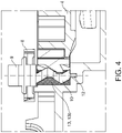
- Fig. 4 shows a third embodiment of the actuator 1 according to the invention.
- the support 13 is implemented as a bearing surface 13b which is included in a casing of the housing of the actuator 1.
- the bearing surface 13b preferably extends at least over a part of the circumference of the spiral pinion 10 that is free of the part of the spiral pinion 10 that is in direct contact with the output spiral gear wheel 4. In this manner, a radial bearing of the spiral of the spiral pinion 10 is ensured in a relatively simple manner, and with a small core diameter of the spiral pinion yet a considerable force can be transmitted.
- the actuator can be particularly advantageously applied in a motor vehicle for adjusting a housing with an exterior vision unit, such as an exterior mirror, camera, LIDAR and/or display.
- the actuator can for instance be advantageously applied in an adjusting instrument for an exterior vision unit for a vehicle, in particular a motor vehicle, to observe and/or monitor the position of the vehicle with respect to the surroundings.
- the adjusting instrument then comprises a housing with an exterior vision unit, such as an exterior mirror, camera, LIDAR and/or display.
- the housing is then adjustable via the actuator relative to a base of the adjusting instrument, to be mounted on the motor vehicle.
- the adjusting instrument is often intended to adjust the exterior vision unit between a park position, for example a fold-in position in which the housing extends substantially along the vehicle, and a work position, for example a drive position in which the housing extends substantially transversely to the vehicle.
- the base of the adjusting instrument then comprises a foot for mounting on an outer part of the body of the motor vehicle, and a shaft extending from the foot along a longitudinal axis of standing orientation with respect to the fixed world, for receiving the housing in a manner pivotable around it.
- the housing is connected to the base via the actuator, so that the pivoting movement by which the carrier folds in and out can be carried out in a driven manner.
- an adjusting instrument for an exterior vision unit for a vehicle comprising:
- the motor and the first stage of the actuator can then, for instance, be carried by the housing, and the spiral gear wheel may be carried by the pivoting shaft.
- Fig. 5 shows a fourth embodiment of the actuator 1 according to the invention.
- Fig. 5 is an exploded perspective view of an actuator 1 including housing 19.
- the housing 19 includes a support shaft 16 for a support spiral pinion 13a for radial bearing of the spiral pinion 10.
- the height H of the reduction mechanism 3 is less than twice the thickness D of the DC motor, and, in particular, is of the same order of magnitude as the thickness D of the DC motor.
- the output spiral gear wheel 4 along its output axis, on its inner side, is provided with a recess 14 with an inner toothing 15 which cooperates with a toothing 17 of a hollow shaft 18.
- the hollow shaft 18 carries the output spiral gear wheel 4 and is bearing-mounted in the housing 19.
- the hollow shaft 18 is provided on its inner side with screw thread 20 for cooperation with the thread of a screw spindle not shown.
- the spindle is suitable in particular for obtaining a linear output movement.
- a strong wear-resistant material of low friction such as bronze or a technical plastic such as HNPE, POM, Nylon or PEPT.
- Such an actuator with a linear output movement can naturally also be obtained by providing the spiral gear wheel 4 with inner thread at the recess 14 for cooperation with the thread of a screw spindle not shown.
- Such a variant of the actuator with a rotation-translation converter on the second stage can be applied in an adjusting instrument for performing a linear adjustment on elements of motor vehicles, for example, adjustment of air guiding screens, in particular air dams.
- air guiding screens are applied for influencing air streams to, for example, a motor housing and/or disc brakes of the motor vehicle by regulation of the air supply.
- the actuators may be used for influencing air streams around the motor vehicle by controlling, for example, screens under and/or on the rear of the motor vehicle to thereby regulate the air resistance. With such screens, for example, the consumption of the motor vehicle can be improved and/or the air resistance can be increased, for example, for a shorter brake path.
- an adjusting instrument for adjusting a screen for a vehicle comprising an actuator and a rotation-translation converter which by its input is coupled with the spiral gear wheel of the actuator, and which by its output is couplable with a spindle.
- the output of the spiral gear wheel is then coupled with a spindle, and the spindle in its turn is coupled with a screen.
- the first stage may also be implemented with multiple series-connected gear wheel pairs or with a first spiral pinion which cooperates with an intermediate spiral gear wheel.
- the first stage may be driven by a different type of DC electric motor, such as a stepping motor or by a brushless DC motor.
Landscapes
- Engineering & Computer Science (AREA)
- General Engineering & Computer Science (AREA)
- Mechanical Engineering (AREA)
- Gear Transmission (AREA)
- Connection Of Motors, Electrical Generators, Mechanical Devices, And The Like (AREA)
Claims (12)
- Actionneur pourvu d'un moteur à courant continu à basse tension (2) qui est couplé, par l'intermédiaire d'un mécanisme de réduction à deux étages (3), à une roue dentée de sortie (4), dans lequel le mécanisme de réduction comprend un premier étage (5) avec une vis sans fin (7) portée sur l'arbre de moteur du moteur à courant continu, ladite vis sans fin (7) dans une transmission à angle droit coopère avec la circonférence d'une roue dentée intermédiaire (8), ladite roue dentée intermédiaire est portée sur un arbre intermédiaire (9) qui porte, le long de son axe, un pignon en spirale (10), et dans lequel le mécanisme de réduction comprend en outre un second étage (11) avec le pignon en spirale (10) qui, dans une transmission parallèle, coopère avec la circonférence de la roue dentée de sortie (4), qui est mise en œuvre en tant qu'une roue dentée en spirale, caractérisé en ce que le pignon en spirale (10) coopère en outre, à sa circonférence, avec un support (13) qui supporte le pignon en spirale à sa circonférence.
- Actionneur selon la revendication 1, dans lequel le pignon en spirale (10) comprend une denture conique avec un angle de dent qui est supérieur à 15°, en particulier un angle de dent qui est entre 15° et 35°.
- Actionneur selon la revendication 1 ou 2, dans lequel le pignon en spirale (10) comprend une seule dent ou deux dents.
- Actionneur selon l'une quelconque des revendications précédentes, dans lequel la longueur axiale du pignon en spirale (10) est choisie de sorte que les dents effectuent au moins une demi-rotation sur la circonférence du pignon en spirale.
- Actionneur selon l'une quelconque des revendications précédentes, dans lequel l'arbre intermédiaire (9) à proximité de l'extrémité du pignon en spirale (10) est pourvu d'un palier.
- Actionneur selon l'une quelconque des revendications précédentes, dans lequel le support est un pignon en spirale de support (13a) ou une surface de palier (13b).
- Actionneur selon l'une quelconque des revendications précédentes, dans lequel le support (13) est placé à l'opposé du côté du pignon en spirale (10) qui est en prise avec la roue dentée en spirale.
- Actionneur selon l'une quelconque des revendications précédentes, dans lequel la roue dentée en spirale est pourvue d'une denture intérieure (15) destinée à coopérer avec une broche.
- Instrument de réglage destiné à régler un écran d'un véhicule, comprenant un actionneur selon l'une quelconque des revendications précédentes, et un convertisseur de rotation en translation qui, par son entrée, est couplé à la roue dentée en spirale (4) et qui, par sa sortie, peut être couplé à une broche.
- Instrument de réglage selon la revendication 9, dans lequel la sortie de la roue dentée en spirale est couplée à une broche, et dans lequel la broche est couplée à un écran.
- Instrument de réglage pour une unité de vision extérieure d'un véhicule, comprenant :- une base, comprenant un pied et un arbre pivotant s'étendant depuis celui-ci le long d'un axe longitudinal,- un logement qui entoure l'arbre pivotant et qui peut pivoter autour de l'axe longitudinal de l'arbre pivotant dans une plage de réglage, entre au moins une position de stationnement et une position de fonctionnement, comprenant en outre un actionneur selon l'une quelconque des revendications 1 à 8 qui est opérationnel entre la base et le logement pour régler le logement dans la plage de réglage par rapport à l'arbre pivotant.
- Instrument de réglage selon la revendication 11, dans lequel le moteur et le premier étage de l'actionneur sont portés par le logement, et dans lequel la roue dentée en spirale est portée par l'arbre pivotant.
Applications Claiming Priority (2)
| Application Number | Priority Date | Filing Date | Title |
|---|---|---|---|
| NL2021341A NL2021341B1 (nl) | 2018-07-18 | 2018-07-18 | Actuator |
| PCT/NL2019/050456 WO2020017966A1 (fr) | 2018-07-18 | 2019-07-17 | Actionneur |
Publications (2)
| Publication Number | Publication Date |
|---|---|
| EP3824203A1 EP3824203A1 (fr) | 2021-05-26 |
| EP3824203B1 true EP3824203B1 (fr) | 2022-09-21 |
Family
ID=63556410
Family Applications (1)
| Application Number | Title | Priority Date | Filing Date |
|---|---|---|---|
| EP19749855.3A Active EP3824203B1 (fr) | 2018-07-18 | 2019-07-17 | Actionneur |
Country Status (7)
| Country | Link |
|---|---|
| US (1) | US11796036B2 (fr) |
| EP (1) | EP3824203B1 (fr) |
| JP (1) | JP7442493B2 (fr) |
| KR (1) | KR102851956B1 (fr) |
| CN (1) | CN112437851B (fr) |
| NL (1) | NL2021341B1 (fr) |
| WO (1) | WO2020017966A1 (fr) |
Families Citing this family (3)
| Publication number | Priority date | Publication date | Assignee | Title |
|---|---|---|---|---|
| US11644380B2 (en) * | 2020-09-29 | 2023-05-09 | Board Of Regents, The University Of Texas System | Integrated rapid infrastructure monitoring systems and methods of using same |
| DE102020216186A1 (de) | 2020-12-17 | 2022-06-23 | Robert Bosch Gesellschaft mit beschränkter Haftung | Vorrichtung zur Verstellung von Sitzkomponenten in einem Fahrzeug, insbesondere einer Rückenlehne |
| DE102022107518A1 (de) * | 2022-03-30 | 2023-10-05 | Kiekert Aktiengesellschaft | Stellantrieb für kraftfahrzeug-technische Anwendungen |
Family Cites Families (16)
| Publication number | Priority date | Publication date | Assignee | Title |
|---|---|---|---|---|
| US2193431A (en) * | 1934-06-18 | 1940-03-12 | Karl K Probst | Power transmission mechanism |
| JPH0469437A (ja) * | 1990-07-10 | 1992-03-04 | Matetsukusu Kk | 自動車のサイドミラー旋回減速装置 |
| JP3872639B2 (ja) * | 2000-08-31 | 2007-01-24 | 株式会社村上開明堂 | 電動格納式ドアミラー |
| NL1017466C2 (nl) | 2001-02-28 | 2002-08-29 | Iku Holding Montfoort Bv | Actuatormechanisme voor het verstellen van de hoekstand van een spiegelelement in een buitenspiegel voor een motorvoertuig, alsmede buitenspiegel voor een motorvoertuig voorzien van een actuatormechanisme. |
| DE10254129B4 (de) * | 2002-11-20 | 2014-10-30 | Cimosys Ag | Elektromotorischer Möbelantrieb zum Verstellen von Teilen eines Möbels relativ zueinander |
| JP2005201381A (ja) * | 2004-01-16 | 2005-07-28 | Asmo Co Ltd | 減速機付モータ |
| JP2006057690A (ja) * | 2004-08-18 | 2006-03-02 | Algonquin Automotive | 電動ラックアンドピニオンアセンブリ |
| DE102008054398A1 (de) * | 2008-12-08 | 2010-06-10 | Brose Fahrzeugteile GmbH & Co. Kommanditgesellschaft, Würzburg | Aktuator für die Betätigung einer Bremse eines Kraftfahrzeugs |
| JP2010261514A (ja) | 2009-05-08 | 2010-11-18 | Toyota Boshoku Corp | 歯車減速機 |
| DE102010003044A1 (de) * | 2010-03-19 | 2011-09-22 | Robert Bosch Gmbh | Mehrstufige Getriebeeinrichtung zur Verstellung einer Baueinheit in einem Fahrzeug |
| JP5754151B2 (ja) | 2011-02-02 | 2015-07-29 | アイシン精機株式会社 | ウォームギヤ装置 |
| EP3116757B1 (fr) * | 2014-03-11 | 2019-12-25 | Continental Teves AG & Co. OHG | Actionneur pour frein de véhicule automobile |
| NL2013510B1 (nl) * | 2014-09-22 | 2016-09-29 | MCI (Mirror Controls International) Netherlands B V | Actuatormechanisme, buitenspiegelinrichting en voertuig. |
| JP2018193007A (ja) * | 2017-05-19 | 2018-12-06 | トヨタ紡織株式会社 | スライド装置 |
| CN107355513B (zh) * | 2017-07-06 | 2023-08-15 | 上海中鹏岳博实业发展有限公司 | 传动结构及后视镜驱动器 |
| US10400881B1 (en) * | 2018-08-22 | 2019-09-03 | Robert Bosch Gmbh | Gear case with mounting arm |
-
2018
- 2018-07-18 NL NL2021341A patent/NL2021341B1/nl active
-
2019
- 2019-07-17 US US17/260,897 patent/US11796036B2/en active Active
- 2019-07-17 EP EP19749855.3A patent/EP3824203B1/fr active Active
- 2019-07-17 KR KR1020217004944A patent/KR102851956B1/ko active Active
- 2019-07-17 CN CN201980048003.3A patent/CN112437851B/zh active Active
- 2019-07-17 JP JP2021501024A patent/JP7442493B2/ja active Active
- 2019-07-17 WO PCT/NL2019/050456 patent/WO2020017966A1/fr not_active Ceased
Also Published As
| Publication number | Publication date |
|---|---|
| US20210293306A1 (en) | 2021-09-23 |
| KR102851956B1 (ko) | 2025-08-28 |
| US11796036B2 (en) | 2023-10-24 |
| JP7442493B2 (ja) | 2024-03-04 |
| WO2020017966A1 (fr) | 2020-01-23 |
| CN112437851B (zh) | 2024-10-25 |
| JP2021531438A (ja) | 2021-11-18 |
| NL2021341B1 (nl) | 2020-02-13 |
| KR20210031510A (ko) | 2021-03-19 |
| CN112437851A (zh) | 2021-03-02 |
| EP3824203A1 (fr) | 2021-05-26 |
Similar Documents
| Publication | Publication Date | Title |
|---|---|---|
| EP3824203B1 (fr) | Actionneur | |
| JP4699381B2 (ja) | 車両用重畳式操向システム | |
| JP4389253B2 (ja) | アクチュエータ機構 | |
| CN102472076B (zh) | 车辆部件、尤其是车身盖的驱动装置 | |
| US20090199667A1 (en) | Modular power actuator | |
| US20050046290A1 (en) | Actuator | |
| CA2536291A1 (fr) | Instrument a direction de visee variable avec actionneurs internes | |
| JP4451523B2 (ja) | 電気式パワーステアリング・ギア | |
| WO2001094088A3 (fr) | Systeme pour dispositifs de granulation | |
| JP4489199B2 (ja) | リニアアクチュエータ | |
| JP2006248339A (ja) | 回転伝動装置 | |
| JP2001078386A (ja) | リニア駆動装置 | |
| US11788610B2 (en) | Drive mechanism for telescopic linear actuator | |
| CN1380951A (zh) | 用于水供暖/冷却和卫生系统的阀致动器 | |
| EP1707850B1 (fr) | Dispositif de transmission | |
| GB2449916A (en) | Variable ratio belt drives | |
| KR200329274Y1 (ko) | 감속기 | |
| JP2007309417A (ja) | 変速機の操作装置 | |
| JP2007519866A (ja) | プロペラ制御装置用ポンプの可逆駆動装置 | |
| KR970038239A (ko) | 차량용 리모트 컨트롤 미러 | |
| JP2006015777A (ja) | 電動パワーステアリング装置 | |
| JP2021014906A (ja) | 動力伝達装置及び電動パワーステアリング装置 | |
| JP2001132804A (ja) | ウォームギァーを利用した無段変速装置 |
Legal Events
| Date | Code | Title | Description |
|---|---|---|---|
| STAA | Information on the status of an ep patent application or granted ep patent |
Free format text: STATUS: UNKNOWN |
|
| STAA | Information on the status of an ep patent application or granted ep patent |
Free format text: STATUS: THE INTERNATIONAL PUBLICATION HAS BEEN MADE |
|
| PUAI | Public reference made under article 153(3) epc to a published international application that has entered the european phase |
Free format text: ORIGINAL CODE: 0009012 |
|
| STAA | Information on the status of an ep patent application or granted ep patent |
Free format text: STATUS: REQUEST FOR EXAMINATION WAS MADE |
|
| 17P | Request for examination filed |
Effective date: 20210122 |
|
| AK | Designated contracting states |
Kind code of ref document: A1 Designated state(s): AL AT BE BG CH CY CZ DE DK EE ES FI FR GB GR HR HU IE IS IT LI LT LU LV MC MK MT NL NO PL PT RO RS SE SI SK SM TR |
|
| DAV | Request for validation of the european patent (deleted) | ||
| DAX | Request for extension of the european patent (deleted) | ||
| GRAP | Despatch of communication of intention to grant a patent |
Free format text: ORIGINAL CODE: EPIDOSNIGR1 |
|
| STAA | Information on the status of an ep patent application or granted ep patent |
Free format text: STATUS: GRANT OF PATENT IS INTENDED |
|
| INTG | Intention to grant announced |
Effective date: 20220506 |
|
| GRAS | Grant fee paid |
Free format text: ORIGINAL CODE: EPIDOSNIGR3 |
|
| GRAA | (expected) grant |
Free format text: ORIGINAL CODE: 0009210 |
|
| STAA | Information on the status of an ep patent application or granted ep patent |
Free format text: STATUS: THE PATENT HAS BEEN GRANTED |
|
| AK | Designated contracting states |
Kind code of ref document: B1 Designated state(s): AL AT BE BG CH CY CZ DE DK EE ES FI FR GB GR HR HU IE IS IT LI LT LU LV MC MK MT NL NO PL PT RO RS SE SI SK SM TR |
|
| REG | Reference to a national code |
Ref country code: GB Ref legal event code: FG4D |
|
| REG | Reference to a national code |
Ref country code: CH Ref legal event code: EP |
|
| REG | Reference to a national code |
Ref country code: DE Ref legal event code: R096 Ref document number: 602019019831 Country of ref document: DE |
|
| REG | Reference to a national code |
Ref country code: IE Ref legal event code: FG4D |
|
| REG | Reference to a national code |
Ref country code: AT Ref legal event code: REF Ref document number: 1520089 Country of ref document: AT Kind code of ref document: T Effective date: 20221015 |
|
| REG | Reference to a national code |
Ref country code: LT Ref legal event code: MG9D |
|
| REG | Reference to a national code |
Ref country code: NL Ref legal event code: MP Effective date: 20220921 |
|
| PG25 | Lapsed in a contracting state [announced via postgrant information from national office to epo] |
Ref country code: SE Free format text: LAPSE BECAUSE OF FAILURE TO SUBMIT A TRANSLATION OF THE DESCRIPTION OR TO PAY THE FEE WITHIN THE PRESCRIBED TIME-LIMIT Effective date: 20220921 Ref country code: RS Free format text: LAPSE BECAUSE OF FAILURE TO SUBMIT A TRANSLATION OF THE DESCRIPTION OR TO PAY THE FEE WITHIN THE PRESCRIBED TIME-LIMIT Effective date: 20220921 Ref country code: NO Free format text: LAPSE BECAUSE OF FAILURE TO SUBMIT A TRANSLATION OF THE DESCRIPTION OR TO PAY THE FEE WITHIN THE PRESCRIBED TIME-LIMIT Effective date: 20221221 Ref country code: LV Free format text: LAPSE BECAUSE OF FAILURE TO SUBMIT A TRANSLATION OF THE DESCRIPTION OR TO PAY THE FEE WITHIN THE PRESCRIBED TIME-LIMIT Effective date: 20220921 Ref country code: LT Free format text: LAPSE BECAUSE OF FAILURE TO SUBMIT A TRANSLATION OF THE DESCRIPTION OR TO PAY THE FEE WITHIN THE PRESCRIBED TIME-LIMIT Effective date: 20220921 Ref country code: FI Free format text: LAPSE BECAUSE OF FAILURE TO SUBMIT A TRANSLATION OF THE DESCRIPTION OR TO PAY THE FEE WITHIN THE PRESCRIBED TIME-LIMIT Effective date: 20220921 |
|
| REG | Reference to a national code |
Ref country code: AT Ref legal event code: MK05 Ref document number: 1520089 Country of ref document: AT Kind code of ref document: T Effective date: 20220921 |
|
| PG25 | Lapsed in a contracting state [announced via postgrant information from national office to epo] |
Ref country code: HR Free format text: LAPSE BECAUSE OF FAILURE TO SUBMIT A TRANSLATION OF THE DESCRIPTION OR TO PAY THE FEE WITHIN THE PRESCRIBED TIME-LIMIT Effective date: 20220921 Ref country code: GR Free format text: LAPSE BECAUSE OF FAILURE TO SUBMIT A TRANSLATION OF THE DESCRIPTION OR TO PAY THE FEE WITHIN THE PRESCRIBED TIME-LIMIT Effective date: 20221222 |
|
| PG25 | Lapsed in a contracting state [announced via postgrant information from national office to epo] |
Ref country code: SM Free format text: LAPSE BECAUSE OF FAILURE TO SUBMIT A TRANSLATION OF THE DESCRIPTION OR TO PAY THE FEE WITHIN THE PRESCRIBED TIME-LIMIT Effective date: 20220921 Ref country code: RO Free format text: LAPSE BECAUSE OF FAILURE TO SUBMIT A TRANSLATION OF THE DESCRIPTION OR TO PAY THE FEE WITHIN THE PRESCRIBED TIME-LIMIT Effective date: 20220921 Ref country code: PT Free format text: LAPSE BECAUSE OF FAILURE TO SUBMIT A TRANSLATION OF THE DESCRIPTION OR TO PAY THE FEE WITHIN THE PRESCRIBED TIME-LIMIT Effective date: 20230123 Ref country code: ES Free format text: LAPSE BECAUSE OF FAILURE TO SUBMIT A TRANSLATION OF THE DESCRIPTION OR TO PAY THE FEE WITHIN THE PRESCRIBED TIME-LIMIT Effective date: 20220921 Ref country code: CZ Free format text: LAPSE BECAUSE OF FAILURE TO SUBMIT A TRANSLATION OF THE DESCRIPTION OR TO PAY THE FEE WITHIN THE PRESCRIBED TIME-LIMIT Effective date: 20220921 Ref country code: AT Free format text: LAPSE BECAUSE OF FAILURE TO SUBMIT A TRANSLATION OF THE DESCRIPTION OR TO PAY THE FEE WITHIN THE PRESCRIBED TIME-LIMIT Effective date: 20220921 |
|
| PG25 | Lapsed in a contracting state [announced via postgrant information from national office to epo] |
Ref country code: SK Free format text: LAPSE BECAUSE OF FAILURE TO SUBMIT A TRANSLATION OF THE DESCRIPTION OR TO PAY THE FEE WITHIN THE PRESCRIBED TIME-LIMIT Effective date: 20220921 Ref country code: PL Free format text: LAPSE BECAUSE OF FAILURE TO SUBMIT A TRANSLATION OF THE DESCRIPTION OR TO PAY THE FEE WITHIN THE PRESCRIBED TIME-LIMIT Effective date: 20220921 Ref country code: IS Free format text: LAPSE BECAUSE OF FAILURE TO SUBMIT A TRANSLATION OF THE DESCRIPTION OR TO PAY THE FEE WITHIN THE PRESCRIBED TIME-LIMIT Effective date: 20230121 Ref country code: EE Free format text: LAPSE BECAUSE OF FAILURE TO SUBMIT A TRANSLATION OF THE DESCRIPTION OR TO PAY THE FEE WITHIN THE PRESCRIBED TIME-LIMIT Effective date: 20220921 |
|
| P01 | Opt-out of the competence of the unified patent court (upc) registered |
Effective date: 20230516 |
|
| REG | Reference to a national code |
Ref country code: DE Ref legal event code: R097 Ref document number: 602019019831 Country of ref document: DE |
|
| PG25 | Lapsed in a contracting state [announced via postgrant information from national office to epo] |
Ref country code: NL Free format text: LAPSE BECAUSE OF FAILURE TO SUBMIT A TRANSLATION OF THE DESCRIPTION OR TO PAY THE FEE WITHIN THE PRESCRIBED TIME-LIMIT Effective date: 20220921 Ref country code: AL Free format text: LAPSE BECAUSE OF FAILURE TO SUBMIT A TRANSLATION OF THE DESCRIPTION OR TO PAY THE FEE WITHIN THE PRESCRIBED TIME-LIMIT Effective date: 20220921 |
|
| PLBE | No opposition filed within time limit |
Free format text: ORIGINAL CODE: 0009261 |
|
| STAA | Information on the status of an ep patent application or granted ep patent |
Free format text: STATUS: NO OPPOSITION FILED WITHIN TIME LIMIT |
|
| PG25 | Lapsed in a contracting state [announced via postgrant information from national office to epo] |
Ref country code: DK Free format text: LAPSE BECAUSE OF FAILURE TO SUBMIT A TRANSLATION OF THE DESCRIPTION OR TO PAY THE FEE WITHIN THE PRESCRIBED TIME-LIMIT Effective date: 20220921 |
|
| 26N | No opposition filed |
Effective date: 20230622 |
|
| PG25 | Lapsed in a contracting state [announced via postgrant information from national office to epo] |
Ref country code: SI Free format text: LAPSE BECAUSE OF FAILURE TO SUBMIT A TRANSLATION OF THE DESCRIPTION OR TO PAY THE FEE WITHIN THE PRESCRIBED TIME-LIMIT Effective date: 20220921 |
|
| PG25 | Lapsed in a contracting state [announced via postgrant information from national office to epo] |
Ref country code: MC Free format text: LAPSE BECAUSE OF FAILURE TO SUBMIT A TRANSLATION OF THE DESCRIPTION OR TO PAY THE FEE WITHIN THE PRESCRIBED TIME-LIMIT Effective date: 20220921 |
|
| PG25 | Lapsed in a contracting state [announced via postgrant information from national office to epo] |
Ref country code: MC Free format text: LAPSE BECAUSE OF FAILURE TO SUBMIT A TRANSLATION OF THE DESCRIPTION OR TO PAY THE FEE WITHIN THE PRESCRIBED TIME-LIMIT Effective date: 20220921 |
|
| REG | Reference to a national code |
Ref country code: CH Ref legal event code: PL |
|
| REG | Reference to a national code |
Ref country code: BE Ref legal event code: MM Effective date: 20230731 |
|
| PG25 | Lapsed in a contracting state [announced via postgrant information from national office to epo] |
Ref country code: LU Free format text: LAPSE BECAUSE OF NON-PAYMENT OF DUE FEES Effective date: 20230717 |
|
| PG25 | Lapsed in a contracting state [announced via postgrant information from national office to epo] |
Ref country code: LU Free format text: LAPSE BECAUSE OF NON-PAYMENT OF DUE FEES Effective date: 20230717 |
|
| REG | Reference to a national code |
Ref country code: IE Ref legal event code: MM4A |
|
| PG25 | Lapsed in a contracting state [announced via postgrant information from national office to epo] |
Ref country code: CH Free format text: LAPSE BECAUSE OF NON-PAYMENT OF DUE FEES Effective date: 20230731 |
|
| PG25 | Lapsed in a contracting state [announced via postgrant information from national office to epo] |
Ref country code: IT Free format text: LAPSE BECAUSE OF FAILURE TO SUBMIT A TRANSLATION OF THE DESCRIPTION OR TO PAY THE FEE WITHIN THE PRESCRIBED TIME-LIMIT Effective date: 20220921 Ref country code: BE Free format text: LAPSE BECAUSE OF NON-PAYMENT OF DUE FEES Effective date: 20230731 |
|
| PG25 | Lapsed in a contracting state [announced via postgrant information from national office to epo] |
Ref country code: IE Free format text: LAPSE BECAUSE OF NON-PAYMENT OF DUE FEES Effective date: 20230717 |
|
| PG25 | Lapsed in a contracting state [announced via postgrant information from national office to epo] |
Ref country code: IE Free format text: LAPSE BECAUSE OF NON-PAYMENT OF DUE FEES Effective date: 20230717 |
|
| PG25 | Lapsed in a contracting state [announced via postgrant information from national office to epo] |
Ref country code: BG Free format text: LAPSE BECAUSE OF FAILURE TO SUBMIT A TRANSLATION OF THE DESCRIPTION OR TO PAY THE FEE WITHIN THE PRESCRIBED TIME-LIMIT Effective date: 20220921 |
|
| PG25 | Lapsed in a contracting state [announced via postgrant information from national office to epo] |
Ref country code: BG Free format text: LAPSE BECAUSE OF FAILURE TO SUBMIT A TRANSLATION OF THE DESCRIPTION OR TO PAY THE FEE WITHIN THE PRESCRIBED TIME-LIMIT Effective date: 20220921 |
|
| PG25 | Lapsed in a contracting state [announced via postgrant information from national office to epo] |
Ref country code: CY Free format text: LAPSE BECAUSE OF FAILURE TO SUBMIT A TRANSLATION OF THE DESCRIPTION OR TO PAY THE FEE WITHIN THE PRESCRIBED TIME-LIMIT; INVALID AB INITIO Effective date: 20190717 |
|
| PG25 | Lapsed in a contracting state [announced via postgrant information from national office to epo] |
Ref country code: HU Free format text: LAPSE BECAUSE OF FAILURE TO SUBMIT A TRANSLATION OF THE DESCRIPTION OR TO PAY THE FEE WITHIN THE PRESCRIBED TIME-LIMIT; INVALID AB INITIO Effective date: 20190717 |
|
| PGFP | Annual fee paid to national office [announced via postgrant information from national office to epo] |
Ref country code: DE Payment date: 20250722 Year of fee payment: 7 |
|
| PGFP | Annual fee paid to national office [announced via postgrant information from national office to epo] |
Ref country code: GB Payment date: 20250722 Year of fee payment: 7 |
|
| PGFP | Annual fee paid to national office [announced via postgrant information from national office to epo] |
Ref country code: FR Payment date: 20250725 Year of fee payment: 7 |
|
| PG25 | Lapsed in a contracting state [announced via postgrant information from national office to epo] |
Ref country code: TR Free format text: LAPSE BECAUSE OF FAILURE TO SUBMIT A TRANSLATION OF THE DESCRIPTION OR TO PAY THE FEE WITHIN THE PRESCRIBED TIME-LIMIT Effective date: 20220921 |