EP3824533B1 - Procédé de l'identification d'un chariot coulissant d'un système linéaire de transport - Google Patents
Procédé de l'identification d'un chariot coulissant d'un système linéaire de transport Download PDFInfo
- Publication number
- EP3824533B1 EP3824533B1 EP19742731.3A EP19742731A EP3824533B1 EP 3824533 B1 EP3824533 B1 EP 3824533B1 EP 19742731 A EP19742731 A EP 19742731A EP 3824533 B1 EP3824533 B1 EP 3824533B1
- Authority
- EP
- European Patent Office
- Prior art keywords
- carriage
- magnetic field
- field generator
- signal
- control signal
- Prior art date
- Legal status (The legal status is an assumption and is not a legal conclusion. Google has not performed a legal analysis and makes no representation as to the accuracy of the status listed.)
- Active
Links
Images


Classifications
-
- H—ELECTRICITY
- H02—GENERATION; CONVERSION OR DISTRIBUTION OF ELECTRIC POWER
- H02P—CONTROL OR REGULATION OF ELECTRIC MOTORS, ELECTRIC GENERATORS OR DYNAMO-ELECTRIC CONVERTERS; CONTROLLING TRANSFORMERS, REACTORS OR CHOKE COILS
- H02P25/00—Arrangements or methods for the control of AC motors characterised by the kind of AC motor or by structural details
- H02P25/02—Arrangements or methods for the control of AC motors characterised by the kind of AC motor or by structural details characterised by the kind of motor
- H02P25/06—Linear motors
- H02P25/064—Linear motors of the synchronous type
-
- B—PERFORMING OPERATIONS; TRANSPORTING
- B65—CONVEYING; PACKING; STORING; HANDLING THIN OR FILAMENTARY MATERIAL
- B65G—TRANSPORT OR STORAGE DEVICES, e.g. CONVEYORS FOR LOADING OR TIPPING, SHOP CONVEYOR SYSTEMS OR PNEUMATIC TUBE CONVEYORS
- B65G54/00—Non-mechanical conveyors not otherwise provided for
- B65G54/02—Non-mechanical conveyors not otherwise provided for electrostatic, electric, or magnetic
-
- H—ELECTRICITY
- H02—GENERATION; CONVERSION OR DISTRIBUTION OF ELECTRIC POWER
- H02K—DYNAMO-ELECTRIC MACHINES
- H02K11/00—Structural association of dynamo-electric machines with electric components or with devices for shielding, monitoring or protection
- H02K11/20—Structural association of dynamo-electric machines with electric components or with devices for shielding, monitoring or protection for measuring, monitoring, testing, protecting or switching
- H02K11/21—Devices for sensing speed or position, or actuated thereby
- H02K11/215—Magnetic effect devices, e.g. Hall-effect or magneto-resistive elements
-
- H—ELECTRICITY
- H02—GENERATION; CONVERSION OR DISTRIBUTION OF ELECTRIC POWER
- H02K—DYNAMO-ELECTRIC MACHINES
- H02K16/00—Machines with more than one rotor or stator
- H02K16/02—Machines with one stator and two or more rotors
-
- H—ELECTRICITY
- H02—GENERATION; CONVERSION OR DISTRIBUTION OF ELECTRIC POWER
- H02K—DYNAMO-ELECTRIC MACHINES
- H02K41/00—Propulsion systems in which a rigid body is moved along a path due to dynamo-electric interaction between the body and a magnetic field travelling along the path
- H02K41/02—Linear motors; Sectional motors
- H02K41/03—Synchronous motors; Motors moving step by step; Reluctance motors
- H02K41/031—Synchronous motors; Motors moving step by step; Reluctance motors of the permanent magnet type
Definitions
- the invention relates to two methods for identifying a carriage of a linear transport system.
- the invention also relates to a device which is set up to carry out all steps of the method or the method for identifying a carriage of a linear transport system.
- the invention also relates to a linear transport system, a computer program and a machine-readable storage medium.
- the patent specification EP 3 044 133 B1 discloses a method for adapting travel profiles of a multiplicity of individually controllable transport elements for transporting containers in a container treatment system along a transport path, the multiplicity of transport elements being movably arranged on the transport path.
- the transport elements are placed in such a way that there is a repulsive interaction between two transport elements that are adjacent along the transport path due to a corresponding magnet arrangement, so that collisions can be avoided or at least weakened.
- a position of a transport element can be determined by means of a multiplicity of sensors, for example magnetic field sensors, arranged along the transport path.
- the sensor can be designed as an optical sensor, electrical sensor, electromagnetic sensor or mechanical sensor, for example by measuring a light reflection on a reflector element of the transport element, by inducing an electromagnetic signal due to the movement of the transport element, by changing the electrical resistance of the sensor using a magnetoresistive effect, for example due to the magnetic flux of a magnetic reference element, for example a permanent magnet, or the reaction element of the transport element, or by local pressure measurement based on the weight of the transport element, the position of the transport element in the area of the sensor can be determined.
- An electromagnetic sensor can be designed as a Hall sensor which also delivers a signal when the magnetic field in which it is located is constant.
- a transport element can comprise an unambiguous identification unit, for example in the form of a bar code, readable memory chip, a printed, glued and / or engraved alphanumeric code, whereby one or more identification detection devices along the transport path identify the transport element, which the corresponding Identification detection device happens, is made possible.
- an unambiguous identification unit for example in the form of a bar code, readable memory chip, a printed, glued and / or engraved alphanumeric code, whereby one or more identification detection devices along the transport path identify the transport element, which the corresponding Identification detection device happens, is made possible.
- the pamphlet DE 10 2011 004348 A1 discloses a method and a position detection device for detecting a position of an element of a drive device designed as a slide and movable by means of a linear motor.
- the object on which the invention is based is to be seen in providing a concept for the efficient identification of a carriage of a linear transport system.
- the concept described here is based on the idea that the different magnetic field generators form a magnetic identification means for the carriages of the linear transport system, by means of which a carriage can be efficiently identified. Identifying in the sense of the description means, in particular, a distinction between at least two carriages. Identification in the sense of the description is therefore not a type of position recognition, but rather enables one slide to be distinguished from the other in an advantageous manner.
- first magnetic identification means of the first slide is formed by means of the first magnetic field or the first magnetic field generator.
- second magnetic identification means of the second slide is formed by means of the second magnetic field or the second magnetic field generator.
- the individual carriages can then be identified efficiently using these two identification means.
- the first magnetic identification means also differs from the second magnetic identification means. An unambiguous identification of the respective carriages via the identification means is thus advantageously made possible.
- a measurement that depends on a magnetic field will therefore provide a different result depending on whether the measurement depends on the first or second magnetic field.
- a measurement signal based on this measurement can then advantageously be used to identify the slide assigned to this measurement signal either as the first or as the second slide.
- the respective runner of the slide is used for this identification, additional identification units, for example in the form of a readable memory chip, do not have to be attached to the slide itself.
- a magnetic field generator provided in addition to a rotor for this identification is used, the rotor can be designed for optimal magnetic interaction with the drive coils.
- a position detection system is usually provided in the linear transport system to detect the position. If one of these magnetic field generators is now changed for position detection, then this magnetic field generator can also be differentiated from the others in addition to the position with the existing position detection system, so that a one-to-one identification is also made possible. Because the position detection system (for example, including Hall sensors) can detect the position over the entire travel path of the carriages, the identification of all carriages works regardless of where they are currently located.
- another magnetic field generator which is different from the rotor, has the advantage that it can be changed free of the rotor, for example free of the rotor's drive magnets, and can be optimized for position detection and identification.
- the signals are not changed by the magnetic fields of the rotor, for example by magnetic fields of the drive magnets, which means that even a low-noise detection can lead to better results with regard to identification.
- First carriages in the sense of the description each include a first runner.
- Second slides in the sense of the description each include a second runner.
- the respective magnetic vector field of a size of the respective magnetic field generator and / or a respective polarity of the respective magnetic field generator and / or a respective orientation of the respective magnetic field generator and / or a respective material of the respective magnetic field generator and / or of a number and / or a distance between the poles of the respective magnetic field generator depends. This means, for example, that the number and / or the spacing of the poles of the first magnetic field generator differ from those of the second magnetic field generator.
- a magnetic field generator within the meaning of the description comprises one or more magnets, for example permanent magnets.
- a magnetic vector field in the sense of the description has, for example, one or more of the following features or properties: a certain distribution of the magnetic field strength and a certain distribution of the magnetic field direction.
- a magnetic vector field in the sense of the description can be influenced or characterized, for example, by means of one or more of the following influencing factors: Size of magnets, shape of magnets, position of magnets, material of magnets, magnetization of magnets, number of magnets.
- Different magnetic field generators therefore differ, for example, in at least one of the above features or properties or influencing factors.
- the magnetic field generators differ from one another at least in their sizes and / or in their polarity and / or in their alignment and / or their respective material and / or in their number of poles and / or in their pole spacing.
- At least one reference value is stored in the controller, which is assigned to one of the two slides, the identification of the slide assigned to the first measurement signal as the first or as the second slide based on a comparison of the first measurement signal with the at least one reference value based.
- the at least one reference value is stored in a controller, from which the reference value is read, the at least one reference value being based, for example, on a previous measurement or, for example, based on expectations.
- the at least one reference value is based on a previous measurement
- the principle of identification based on a saturated inductance is explained below in the explanations further described with regard to the embodiment with regard to the saturation position (see also Fig. 8 and associated description of the figures).
- one or more specific positions were measured to determine which drive coil is sufficiently saturated by one of the drive magnets of the slide located at the specific position, and previously, for example, it was also measured in which direction (travel direction) the slide must be moved in order to close the drive coil further to saturate or to bring out of saturation.
- the first and / or the second magnetic field generator can be measured beforehand (for example using one or more Hall sensors), with the measurement signals corresponding to this measurement being stored as reference values in the controller, so that the current measurement signal is compared to two previously measured and in the Control stored reference values can be compared.
- an identification based on an embodiment comprising outputting a current vector control signal (see also Figure 7 and associated description of the figures) and comprising a detection of one from the output of the current vector control signal resulting movement of a slide can be measured beforehand for the first and / or second magnetic field generator, for example, in which direction the corresponding slide moves with which current vector control signal, so that this result can be used as a reference value for a later measurement.
- At least one second measurement signal assigned to the other of the two slides is received, which is based on a second measurement which depends on the magnetic field of the magnetic field generator of the other of the two slides, the identification of the slide assigned to the first measurement signal as the first or second slide is based on a comparison of the first measurement signal with the at least one received second measurement signal.
- a second control signal is applied to the stator, which has at least two drive coils, which triggers a second measurement which depends on the magnetic vector field of the magnetic field generator of the two carriages, a second measurement signal being received which is based on the second measurement based.
- This embodiment is based on the fact that different runners cause different driving behavior in the sledges.
- the slide is driven faster or slower, for example.
- the slide moves in a certain direction depending on the generated magnetic field of the corresponding magnetic field generator.
- the carriage can then be identified via this, that is to say via the direction and / or via the speed, for example.
- the two directions of travel with respect to the first and second carriages are opposite to one another when the first current vector control signal is the same.
- the corresponding carriage can thus be efficiently identified as either the first or the second carriage via a travel direction of the carriage.
- a first drive direction is determined in which the carriage driven based on the output first current vector control signal has moved after the display of the at least one first current vector control signal, the one assigned to the first measurement signal Slide is identified based on the determined first drive direction as the first or as the second slide.
- this type of identification is very robust. This is because the polarity or the sign are significantly different than if only one variable or amplitude were evaluated. Furthermore, this type of identification can be implemented quickly and easily in an already existing linear transport system.
- a first Setpoint current control signal for energizing the one drive coil with a first setpoint alternating current is output, the at least one first measurement signal comprising a first voltage measurement signal which represents a derived coil voltage of the drive coil energized with the first setpoint alternating current after the outputting of the first setpoint current control signal.
- the derived coil voltage corresponds to the nominal voltage that results at the output of a current regulator for energizing the drive coils and which corresponds to the nominal voltage calculated in the current regulator.
- the technical advantage is achieved that the slide or slides do not have to move for identification.
- a second target current control signal for energizing the one drive coil with a first target direct current is output, with a second voltage measurement signal being received which shows a derived coil voltage of the drive coil energized with the first target direct current after the second Setpoint current control signal, with an ohmic voltage component of the derived coil voltage of the first voltage measurement signal being calculated based on the second voltage measurement signal, the resistive voltage component being subtracted from the derived coil voltage of the first voltage measurement signal in order to determine a coil voltage adjusted from the resistive voltage component, wherein the carriage assigned to the first measurement signal is identified as the first carriage or as the second carriage based on the determined corrected coil voltage.
- At least one of the magnetic field generators comprises at least one permanent magnet and / or at least one coil, the at least one permanent magnet and / or the at least one coil each being used as a drive magnet or rotor of the linear motor.
- the linear transport system comprises a guide rail for guiding the carriages.
- the carriages comprise running rollers and, for example, the guide rail comprises running surfaces on which the running rollers can roll.
- the linear transport system comprises a position detection system which is set up to determine a current position of the carriages and to provide position signals corresponding to the determined current position.
- a drive coil in the sense of the description comprises, for example, a coil core, which can also be referred to as a stator core, the drive coil being wound around the coil core.
- Fig. 1 shows a linear transport system 101 in a side view.
- the linear transport system comprises a first carriage 103 which is guided along a guide rail 105.
- the guide rail 105 can be part of the linear transport system 101.
- the linear transport system 101 includes a linear motor 107 for driving the first carriage 103.
- the linear motor 107 comprises a first motor module 109, a second motor module 111, a third motor module 113, a fourth motor module 115, a fifth motor module 117 and a sixth motor module 119.
- the individual motor modules are mechanically and electrically connected to one another and are arranged along the guide rail 105 .
- the individual motor modules comprise several in Fig. 1 Drive coils, not shown in detail, which form a stator of the linear motor 107.
- a first encoder flag 121 is arranged on the first slide 103.
- the first encoder flag 121 interacts with a position detection system (not shown) of the linear transport system 101 in order to determine a position of the first carriage 103.
- the linear transport system 101 comprises a second slide 123 which is guided by means of the guide rail 105.
- the linear motor 107 drives the second carriage 123.
- a second encoder flag 125 is arranged on the second slide 123, which, analogously to the first transmitter flag 121 of the first slide 103, interacts with the position detection system (not shown) in order to determine a position of the second slide 123.
- the first carriage 103 comprises a first carrier 127 and a second carrier, which is not visible due to the side view, and which lies opposite the first carrier 127.
- the motor module 109 is located between the first carrier 127 and the second carrier.
- On the first carrier 127 are in Fig. 1 Arranged drive magnets, not shown, which form a first magnetic field generator for generating a first magnetic field.
- These drive magnets are arranged on an inside of the first carrier 127 and are of the type shown in FIG Fig. 1 facing the front of the motor modules 109 to 119 shown.
- a plurality of drive magnets which are likewise not visible here, are arranged on an inside of the second carrier.
- these drive magnets are opposite the rear side of the motor modules 109 to 119.
- the Drive coils of the motor modules 109 to 119 generate corresponding magnetic fields depending on a corresponding current supply, which interact with the magnetic fields of the drive magnets in order to drive the first carriage 103 and thus form a first runner of the linear motor 107.
- the second slide 123 also has a third carrier 129, on the inside of which a plurality of drive magnets are arranged.
- the second slide 123 also has a fourth carrier, which is shown in FIG Fig. 1 is not visible.
- a plurality of drive magnets are also arranged on an inside of the fourth carrier.
- the drive magnets of the second slide 123 form a second magnetic field generator for generating a second magnetic field and thus form a second rotor of the linear motor 107.
- the first magnetic field generator of the first carriage 103 differs from the second magnetic field generator of the second carriage 123 at least in its magnetic vector field.
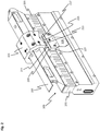
- Fig. 2 shows the first motor module 109 with a partial section of the first carriage 103 in a perspective view.
- first encoder flag 121 and the first carrier 127 are shown for the first slide 103, the second carrier being based on the in FIG Fig. 2 chosen perspective is not visible.
- the first motor module 109 comprises a plurality of coil cores 203 which are arranged next to one another and which can generally also be referred to as stator cores.
- Every second of the coil cores 203 is with an in Fig. 2 wrapped coil, not shown. This means that every second coil core 203 is unwound, that is to say is free of a coil.
- each coil core 203 is wrapped with a coil.
- the second motor module 111, the fourth motor module 115 and the fifth motor module 117 of the linear transport system 101 are analogous to the first motor module 109 according to FIG Fig. 2 built up.
- the third motor module 113 and the sixth motor module 119 are constructed essentially analogously to the first motor module 109, with one difference being a geometry that is predetermined by the guide rail 105.
- a first magnet 209, a second magnet 211, a third magnet 213, a fourth magnet 215 and a fifth magnet 217 are arranged on the inside of the first carrier 127 facing the coil cores 203 or the first motor module 109.
- five magnets are also arranged on the second carrier, which is covered by the first motor module 109 and therefore not visible, in such a way that they each face the coil cores 203 or the first motor module 109 and in particular the first to fifth magnets 209 to 217 of the first carrier 127 are opposite.
- these ten magnets each form five pairs of magnets.
- the respective magnetic poles of the magnets lying opposite one another are arranged opposite one another, that is to say point in opposite directions or have opposite magnetic polarities or magnetic polarities.
- These ten magnets are drive magnets and form the rotor of the linear motor. They are also part of the first magnetic field generator.
- the drive magnets are permanent magnets, for example.
- Fig. 3 shows a greatly simplified sectional plan view of the first carriage 103 and the first motor module 109 with the coil cores 203 and the coils 601.
- the top view shows the first carrier 127 and the opposite second carrier 301 of the first carriage 103.
- the second carrier 301 has an inner side facing the coil cores 203 and the first motor module 109, on which a sixth magnet 305, a seventh magnet 307, is attached eighth magnet 309, a ninth magnet 311 and a tenth magnet 313 are arranged.
- These sixth to tenth magnets 305 to 313 of the second carrier 301 form, as already described above, five magnet pairs with the first to fifth magnets 209 to 217 of the first carrier 127.
- Numeral 317 indicates the current direction of a current flowing through the coils.
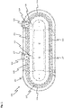
- FIG. 4 shows an even further simplified, schematic plan view of the first carriage 103.
- FIG. 11 shows an even further simplified, schematic plan view of the second slide 123.
- the first motor module is in FIGS. 4 and 5 only shown schematically.
- the letter “N” stands for the north pole of the corresponding drive magnet of the first carriage 103 or of the second carriage 123.
- the letter “S” also stands for the south pole of the corresponding drive magnet of the first carriage 103 or of the second carriage.
- the drive magnets of the first and second carriages 103, 123 are each aligned with either their south pole S or their north pole N facing the first motor module 109.
- the first magnet 209 points with its south pole S in the direction of the first motor module 109 and with its north pole N in the direction of the first carrier 127.
- the second magnet 211 points with its north pole N in the direction of the first motor module 109 and with its south pole S in Direction of the first carrier 127.
- the third magnet 213 points with its south pole S in the direction of the first motor module 109 and with its north pole N in the direction of the first carrier 127.
- the fourth magnet 215 points with its north pole N in the direction of the first motor module 109 and with its south pole S in the direction of the first carrier 127.
- the fifth magnet 217 points with its south pole S in the direction of the first motor module 109 and with its north pole N in the direction of the first carrier 127.
- the sixth magnet 305 which forms a magnetic field pair with the first magnet 209, points with its north pole N in the direction of the first motor module 109 and with its south pole S in the direction of the second carrier 301 forms the second pair of magnets, points with its south pole S in the direction of the first motor module 109 and with its north pole N in the direction of the second carrier 301.
- the eighth magnet 309 which forms a third magnet pair with the third magnet 213, points with its north pole N in the direction of the first motor module 109 and with its south pole S in the direction of the second carrier 301.
- the tenth magnet 313, which forms a fifth magnet pair with the fifth magnet 217 shows with its north pole N in the direction of the first motor module 109 and with its south pole S in the direction of the second carrier 301.
- the second carriage 123 comprises the third carrier 129 and the fourth carrier 501.
- An eleventh magnet 503, a twelfth magnet 505, a thirteenth magnet 507, a fourteenth magnet 509 and a fifteenth magnet 511 are arranged on an inside of the third carrier 129 facing the motor module 109.
- a sixteenth magnet 513, a seventeenth magnet 515, an eighteenth magnet 517, a nineteenth magnet 519 and a twentieth magnet 521 are arranged on the inside of the fourth carrier 501 facing the motor module 109.
- the eleventh magnet 503 and the sixteenth magnet 513 form a first magnet pair and the twelfth magnet 505 and the seventeenth magnet 515 form a second magnet pair and the thirteenth magnet 507 and the eighteenth magnet 517 form a third magnet pair and form the fourteenth
- the magnet 509 and the nineteenth magnet 519 constitute a fourth magnet pair
- the fifteenth magnet 511 and the twentieth magnet 521 constitute a fifth magnet pair.
- These ten magnets of the second slide 123 form drive magnets or the rotor of the linear motor.
- the eleventh magnet 503 thus points with its north pole N in the direction of the first motor module 109 and with its south pole S in the direction of the third carrier 129.
- the twelfth magnet 505 shows with its south pole S in the direction of the first motor module 109 and with its north pole N in the direction of the third carrier 129.
- the thirteenth magnet 507 points with its north pole N in the direction of the first motor module 109 and with its south pole S in the direction of the third carrier 129.
- the fourteenth magnet 509 points with its south pole S in the direction of the first motor module 109 and with its north pole N in the direction of the third carrier 129.
- the fifteenth magnet 511 points with its north pole N in the direction of the first motor module 109 and with its south pole S in the direction of the third carrier 129.
- the sixteenth magnet 513 points with its south pole S in the direction of the first motor module 109 and with its north pole N in the direction of the fourth carrier 501.
- the seventeenth magnet 515 points with its north pole N in the direction of the first motor module 109 and with its south pole S in the direction of the fourth carrier 501.
- the eighteenth magnet 517 points with its south pole S in the direction of the first motor module 109 and with its No rdpol N in the direction of the fourth carrier 501.
- the nineteenth magnet 519 points with its north pole N in the direction of the first motor module 109 and with its south pole S in the direction of the fourth carrier 501.
- the twentieth magnet 521 points with its south pole S in the direction of the first motor module 109 and with its north pole N in the direction of the fourth carrier 501.
- the magnets of the two carriages 103 and 123 are each identical, but differ in terms of their north-south pole alignment and thus in their magnetic vector field.
- the corresponding pole orientations of the individual magnets in the second slide 123 are exactly opposite to the corresponding pole orientations of the magnets in the first slide 103 in relation to the orientation towards the first motor module 109.
- the individual magnets of the second carriage 123 are rotated by 180 ° in relation to their alignment in the direction of the first motor module 109 compared to the corresponding magnets of the first carriage 103.
- the second slide 123 with its second magnetic field generator is identical to the first slide 103 with its first magnetic field generator, but was rotated by 180 ° with respect to the longitudinal alignment of the first motor module 109 and placed on the guide rail 105 so that the corresponding magnetic Differentiate the vector field of the first carriage 103 from the magnetic vector field of the second carriage 123 during the operation of the linear transport system 101.
- the two carriages behave differently when the drive coils are supplied with the same current.
- the same current vector which is distributed to the drive coils via a commutation rule, one of the two carriages moves in the direction of the current vector, whereas the other of the two carriages moves away from this current vector.
- a current pointer can be switched once with a positive amount of current and once with a negative amount of current.
- the different arrangement or alignment of the individual poles of the magnets of the two carriages causes a different reaction in both cases.
- a statement can then be made about whether the driven slide is the first slide 103 or the second slide 123.
- the current pointer can be connected in such a way that it initially does not generate any force on the corresponding carriage (regardless of the corresponding pole alignment of the drive magnets) in relation to a current position of the carriage.
- the current pointer is therefore in a rest position in terms of its force effect.
- the detection of the movement of the corresponding slide can be carried out, for example, using the position detection system, which provides position signals corresponding to a current position of the slide. Based on these position signals, it can be determined, for example, whether the slide is moving or not, or in which direction the slide has moved or has moved.
- an amount of the current pointer is increased until a minimum movement is detected or recognized, which can for example be detected in an analog manner by means of the position detection system.
- a movement of about 100 ⁇ m is sufficient to recognize the direction of travel of the corresponding slide and to identify the slide.
- the corresponding slide is moved back to its original position after its identification, from which the method for identification started.
- Fig. 6 shows a very simplified side view of the first motor module 109 with the first carrier 127.
- FIG. 6 The selected illustration shows a coil 601 around every second coil core 203.
- a Hall sensor is arranged below each of the unwound coil cores 203.
- FIG. 6 The illustration shown is a first Hall sensor 605, a second Hall sensor 607, a third Hall sensor 609 and a fourth Hall sensor 611.
- more or fewer than these four Hall sensors are provided.
- each unwound coil core 203 It is not necessary for a separate Hall sensor to be located under each unwound coil core 203. It is sufficient, for example, that the linear transport system as a whole comprises four Hall sensors, each of which is arranged under an unwound coil core 203. At this point it should be noted that at least 1 Hall sensor is sufficient.
- a distance between two Hall sensors is, for example, the length of a carrier in the direction of travel.
- the first Hall sensor 605 and the fourth Hall sensor 611 are sufficient for identification.
- the magnetic field of the corresponding magnetic field generator is measured by means of the Hall sensors and is stored as a reference.
- a currently measured magnetic field can then be compared with the pre-stored reference values so that, based on this comparison, the carriage assigned to the corresponding magnetic field can be identified either as the first carriage 103 or as the second carriage 123.
- the reference number 603 points to a double arrow which indicates a possible direction of movement of the slide.
- a distance 613, symbolically represented by a double arrow, between two Hall sensors is, for example, between 10 mm and 20 mm, in particular 16.6 mm. This distance 613 is predetermined in particular by a distance between the coil cores 203.
- the Hall sensors are therefore preferably arranged under the unwound coil cores 203, since more installation space is available here compared to the wound coil cores. So that means that the Hall sensors are closer to the Drive magnets of the carriages can be arranged compared to the wound coils 601.
- the first and / or the second magnetic field generator is different from the first or second runner of the first or second slide 103, 123.
- the first slide 103 has, in addition to the first rotor, a first magnetic field generator which is not used to drive the first slide 103.
- the first magnetic field generator is therefore provided in addition to the drive magnets of the first carriage 103, for example.
- the second slide 123 has, in addition to the second rotor, a second magnetic field generator which is not used to drive the second slide 123.
- the second magnetic field generator is therefore provided in addition to the drive magnets of the second slide 123, for example.
- a slide which has an additional magnetic field generator in addition to its drive magnets, is identified according to one embodiment by means of a magnetic field measurement of the magnetic field generated by means of the additional magnetic field generator using one or more Hall sensors.
- FIG. 10 shows a flowchart of a first method for identifying a carriage of the linear transport system 101.
- the method starts in a first step 701.
- a first position signal is received which represents a first position of one of the two carriages 103, 123.
- the first and also the following position signals can be provided, for example, by means of the position detection system, which determines a current position of the carriages.
- the first position can also be referred to as a start position.
- a first current vector control signal for distributing at least one first current vector based on a first commutation rule is switched on via the drive coils of the linear transport system 101 in order to drive the carriage located at the first position.
- the drive coils are appropriately energized in order to drive the carriage.
- the fourth step 706 further comprises receiving a second position signal, the second position signal representing a position of the driven carriage after the outputting of the first current vector control signal.
- a fifth step 707 based on the first position signal and the second position signal, it is checked whether the carriage has moved a predetermined minimum distance away from the first position.
- step 707 If the checking in accordance with fifth step 707 has shown that the carriage has not yet moved away from the first position by at least the minimum distance, the method is carried out continued in the third step 705.
- an increase in an instantaneous amplitude of the first current vector control signal is provided.
- a sixth step 709 provides that a current position of the slide, which corresponds to the position of the slide at the end of fifth step 707 is stored.
- a movement value corresponding to the movement of the slide which corresponds to the difference between the starting position and the current position at the end of the fifth step 707, is saved.
- a seventh step 711 it is provided that there is a wait until the carriage has stopped. This can be determined based on receiving further second position signals.
- the second position signal corresponding to the stopping position of the slide is stored for later identification of the slide.
- a second current vector control signal for distributing at least one second current vector based on the first commutation rule is output via the drive coils in order to drive the carriage located at the stopping position.
- the second current vector is opposite to the first current vector. This means that the second current vector points in the opposite direction with respect to the first current vector. If, for example, a positive target current is output based on the first current vector, the eighth step 713 provides that a negative target current is output based on the second current vector (or vice versa), which does not differ from the positive target current except for the sign .
- a third position signal is also received, which represents a position of the carriage after the second current vector control signal has been output.
- a tenth step 715 analogously to the fifth step 707, it is checked, based on the third position signal, whether the carriage has moved the predetermined minimum distance from the stopping position in the opposite direction of travel.
- step eighth 713 If the tenth step 715 has shown that the carriage has not yet moved the predetermined minimum distance in the opposite direction of travel, the method is continued in step eighth 713.
- an increase in an instantaneous amplitude of the second current vector control signal is provided.
- an eleventh step 717 provides that a current position of the carriage, which is the position of the carriage at the end of the tenth step 715 is stored.
- a movement value corresponding to the movement of the slide which corresponds to the difference between the position at the end of the fifth step 707 and the current position at the end of the tenth step 715, is saved .
- a twelfth step 719 reference values or expected values are read out from the control, which define which slide moves in which direction given a positive and negative setpoint current.
- a comparison with the above-described received second and third position signals can then be carried out with the corresponding energization in order to determine whether the carriage that was started from the first position is the first or the second slide acts.
- the carriage can thus be identified as the first or as the second carriage.
- a first identification signal 721 which represents an identification of the slide as the first slide
- a second identification signal 723 is output which represents an identification of the carriage as the second carriage.
- an error signal 725 is output.
- the eighth step 713 to eleventh step 717 can be dispensed with, and the second position signal determined in the fourth step 706 is compared directly in the twelfth step 719 with a reference value that has been read out.
- the described method can be dispensed with reading out reference values or expected values from a controller, which define which slide moves in which direction given a positive and negative setpoint current.
- a comparison of the second position signal determined in the fourth step 706 and the third position signal determined in the ninth step 714 is carried out.
- One of the second or third position signals is then assigned to a first carriage and a first identification signal 721 is output accordingly, which is a Identification of the sled represented as the first sled.
- the other of the second or third position signals is then assigned to a second slide and a second identification signal 723 is output accordingly, which represents an identification of the slide as the second slide.
- a second identification signal 723 is output accordingly, which represents an identification of the slide as the second slide.
- any differentiation between the carriages as the first carriage or the second carriage is made.
- this can be completely sufficient for some practical applications. If, for example, a plurality of carriages are operated in a transport system and only one carriage has a magnetic field generator that differs from the other carriages, then only the second position signal of this carriage will have a different directional sign in relation to the movement carried out after going through the process steps mentioned, since all other sleds were moved in a different direction.
- the first identification signal 721 can be assigned to this one slide and the second identification signal 723 can be assigned to all other slides and output accordingly.
- a position detection system is therefore necessarily provided for a position detection of the carriages in order to detect the corresponding positions of the carriages.
- FIG. 8 shows a flowchart of a second method for identifying a carriage of the linear transport system 101.
- the method starts with the first step 801.
- a position signal is received which represents a current position of one of the two carriages.
- one of the drive coils is selected which is used for a saturation measurement. For example, it is provided that that one of the drive coils is used or selected which is most saturated by a drive magnet.
- a first target current control signal for energizing the selected drive coil with a first target alternating current is output in order to energize the selected drive coil with the first target alternating current.
- the third step 805 further comprises receiving a first voltage measurement signal which represents a derived coil voltage of the drive coil energized with the first target alternating current after the output of the first target current control signal.
- a fourth step 807 it is then provided that a second setpoint current control signal for energizing the selected drive coil with a first setpoint direct current is output, the fourth step 807 further comprising receiving a second voltage measurement signal which is a derived coil voltage that corresponds to the first setpoint Represented direct current energized drive coil after outputting the second target current control signal.
- the fourth step 807 can also be carried out before the third step 805.
- a Fifth step 809 calculates the inductive voltage component of the voltage value with the setpoint alternating current applied.
- the coil voltage measured when the target alternating current is supplied with current is corrected for this Ohmic voltage component, that is to say subtracted.
- a positive and a negative peak value of the coil voltage of the drive coil are calculated based on the adjusted coil voltage.
- the energized drive coil will either go more into saturation or go out of saturation, which has an influence on the inductance of the drive coil, which in turn can be measured via the coil voltage.
- a seventh step 813 it is then provided that these pre-stored reference values are called up or read out and compared with the measured values in order to identify the slide as the first slide or as the second slide.
- a first identification signal 815 is output which represents an identification of the carriage as the first carriage.
- a second identification signal 817 is output which represents an identification of the carriage as the second carriage.
- the position of the carriages is also ascertained or determined in this way, so that advantageously, for example, a separate position detection system for detecting the position of the carriages does not have to be used for identification or separate Hall sensors do not have to be provided.
- a sensorless (with regard to identification) process can be implemented.
- the distances between the drive coils and the distances between the drive magnets are set in such a way that there are no positions for one of the two carriages on which the magnetic field generator of the one carriage has a drive coil Moving one carriage in a certain direction brings saturation, the magnetic field generator of the other of the two carriages also saturating this drive coil at a different position of the other carriage when the other carriage is moved in exactly the same certain direction.
- the fourth step 807 and the ninth step 809 can be dispensed with and the first voltage measurement signal determined in the third step 805 is directly read out in the seventh step 813 with a reference value compared.
- a first identification signal 815 which represents an identification of the carriage as the first carriage
- a second identification signal 817 is output which identifies the carriage as the second Sled represents.
- the seventh step 813 it is possible to dispense with reading out reference values or expected values from a controller.
- the seventh step 813 only a comparison of the first voltage measurement signal determined in the third step 805 and the second voltage measurement signal determined in the fourth step 807 is carried out.
- One of the first or second voltage measurement signals is then assigned to a first slide and accordingly a first identification signal 815 is output which represents an identification of the slide as the first slide.
- the other of the first or second voltage measurement signals is then assigned to a second slide and accordingly a second identification signal 817 is output which represents an identification of the slide as the second slide.
- any differentiation between the carriages as the first carriage or the second carriage is made.
- the determination of the first position signal according to the second step 803 can be dispensed with.
- a first target current control signal for energizing all drive coils located in the transport system 101 with a first target alternating current is output in order to energize all drive coils with the first target alternating current. All further process steps then follow as described above.
- the use of a position detection system for the identification of the carriages can be dispensed with, insofar as the corresponding positions of the carriages do not necessarily have to be recorded separately here.
- Fig. 9 shows a device 901 which is set up to carry out all steps of the method for identifying a carriage in a linear transport system according to the first and / or according to the second aspect.
- the device 901 comprises an input 903 which is set up to receive at least one first measurement signal assigned to one of the two carriages, which is based on a first measurement which depends on the magnetic field of the magnetic field generator of the one of the two carriages.
- the device 901 further comprises a processor 905 which is set up to identify the slide assigned to the first measurement signal as the first slide or as the second slide based on the at least one first measurement signal.
- the device 901 comprises an output 907 which is set up to output a first or second identification signal, which represents an identification of the carriage assigned to the first measurement signal as the first or the second carriage.
- a plurality of processors are provided instead of the one processor 905.
- the input 903 comprises a first communication interface which is set up to receive signals, for example measurement signals, via a communication network.
- the communication network comprises an EtherCAT communication network.
- the output 907 comprises a second communication interface which is set up to output signals, for example identification signals and / or control signals, via the communication network.
- the device 901 comprises a communication interface which combines the functionalities of the first communication interface and the second communication interface.
- Fig. 10 shows a machine-readable storage medium 1001.
- a computer program 1003 is stored on the machine-readable storage medium 1001, which comprises instructions which, when the computer program 1003 is executed by a computer, for example by the device 901 of FIG Fig. 9 to cause it to carry out a method of identifying a carriage of a linear transport system.
- the concept described here is based, among other things, on the fact that magnetic field generators are arranged on the slides of a linear transport system, some of which generate different magnetic fields, so that the corresponding magnetic field generators differ at least in terms of their magnetic vector field.
- a respective magnetic identification means is formed, by means of which the individual carriages of the linear transport system can be efficiently identified.
- the magnetic field generator is part of the rotor.
- the drive magnets of the carriages are used for their identification.
- these magnets are not the drive magnets, but additional magnets that are arranged on the slide in addition to the drive magnets, that is to say in addition to the rotor. These additional magnets can also, for example perform other tasks. For example, these additional magnets can also be used for position detection.
- the correspondingly generated magnetic field is measured by means of one or more Hall sensors. This measured magnetic field is compared, for example, with a reference magnetic field in order to identify the corresponding slide as the first or as the second slide.
- the slide is identified based on its driving behavior. Because depending on the generated magnetic field, the slides will behave differently with the same current vector control signal. For example, one carriage moves in a first direction of travel and the second carriage moves in the opposite direction of travel in relation to this direction of travel when the same current vector is applied.
- one embodiment provides for the carriage to be identified by measuring a direction-dependent inductance of a drive coil (the above saturation measurement).
- the principle of saturation measurement is based on the fact that when a drive coil is saturated, more precisely the wound core of the drive coil is saturated, its inductance drops. This means that less voltage is required for a certain change in current.
- a target alternating current for example a sinusoidal target alternating current
- the coil voltage corresponding to this target alternating current being derived. If the applied target alternating current saturates the drive coil further in one direction, the coil voltage in this direction becomes lower compared to the reverse case when the coil is brought out of saturation with the reversed target alternating current and its inductance increases.
- the drive coil is brought further into saturation or is brought out of saturation, which can then be determined by measuring the coil voltage applied to the drive coil.
- the formulation that a drive coil is brought into saturation means or stands for that the coil core (stator core) wound around by means of the drive coil is brought into saturation.
- a reference saturation measurement is carried out for the first and for the second slide in order to store the corresponding coil voltages as reference measured values. These stored measured values can then be read out later during the operation of the linear transport system and compared with the then current measured values in order to identify the corresponding slide as the first or as the second slide.
- one embodiment provides, for example, that a target direct current, for example a target direct current of 3 A, is applied to the drive coil.
- the coil voltage then applied to the drive coil is independent of the inductance of the coil, so that an ohmic voltage component can be determined from this, which can be subtracted from the voltage measurement signal when the target alternating current is energized.
- the measurement curves of the coil voltages assigned to the two carriages can be distinguished even more clearly, which enables efficient identification.
Landscapes
- Engineering & Computer Science (AREA)
- Power Engineering (AREA)
- Physics & Mathematics (AREA)
- Chemical & Material Sciences (AREA)
- Combustion & Propulsion (AREA)
- Electromagnetism (AREA)
- Microelectronics & Electronic Packaging (AREA)
- Control Of Linear Motors (AREA)
- Non-Mechanical Conveyors (AREA)
- Linear Motors (AREA)
Claims (8)
- Procédé permettant d'identifier un chariot (103, 123) d'un système de transport linéaire (101), le système de transport linéaire (101) comprenant un premier chariot (103), un deuxième chariot (123), une unité de commande, un rail de guidage (105) et un moteur linéaire (107) pour entraîner le premier et le deuxième chariot (103, 123) le long du rail de guidage (105), le moteur linéaire (107) comprenant un stator doté de modules de moteur (109, 111, 113, 115, 117, 119) présentant au moins deux bobines d'entraînement et un premier et un deuxième rotor, les modules de moteur (109, 111, 113, 115, 117, 119) reliés mécaniquement et électriquement les uns aux autres étant disposés le long du rail de guidage (105), le premier rotor étant disposé sur le premier chariot (103) et le deuxième rotor étant disposé sur le deuxième chariot (123), le premier chariot (103) présentant un premier générateur de champ magnétique qui présente plusieurs aimants alignés le long du rail de guidage (105) et étant aménagé pour générer un premier champ magnétique, et le deuxième chariot (123) présentant un deuxième générateur de champ magnétique qui présente plusieurs aimants alignés le long du rail de guidage (105) et étant aménagé pour générer un deuxième champ magnétique, les aimants du premier générateur de champ magnétique et les aimants du deuxième générateur de champ magnétique étant alignés en étant tournés vers les modules de moteur (109, 111, 113, 115, 117, 119) respectivement en alternance avec le pôle sud (S) et le pôle nord (N), le premier générateur de champ magnétique étant différent du deuxième générateur de champ magnétique au moins par son champ magnétique vectoriel dans lequel l'alignement polaire des aimants du premier générateur de champ magnétique du premier chariot (103) est tourné de 180°, et donc exactement opposé, par rapport à l'alignement polaire des aimants du deuxième générateur de champ magnétique du deuxième chariot (123) relativement à l'alignement longitudinal par rapport aux modules de moteur (109, 111, 113, 115, 117, 119) de sorte que lorsque l'on observe les premier et deuxième générateurs de champ magnétique avec les premier et deuxième chariots (103, 123) posés sur le rail de guidage (105), le premier aimant du premier générateur de champ magnétique est aligné en étant tourné vers les modules de moteur (109, 111, 113, 115, 117, 119) avec le pôle sud (S) et le premier aimant du deuxième générateur de champ magnétique est aligné en étant tourné vers les modules de moteur avec le pôle nord (N),
comprenant les étapes suivantes consistant à :appliquer (705, 803) un premier signal de commande au stator présentant au moins deux bobines d'entraînement, qui déclenche une première mesure qui dépend du champ magnétique vectoriel des générateurs de champ magnétique des deux chariots (103, 123),recevoir (706, 805) au moins un premier signal de mesure associé à l'un des deux chariots (103, 123) et qui est basé sur la première mesure,identifier (719, 813) le chariot (103, 123) associé au premier signal de mesure comme le premier chariot (103) ou comme le deuxième chariot (123) sur la base au moins du premier signal de mesure, au moins une valeur de référence étant enregistrée dans l'unité de commande qui est associée à l'un des deux chariots (103, 123), l'identification (719, 813) du chariot (103, 123) étant basée sur une comparaison du premier signal de mesure avec ladite au moins une valeur de référence,sortir un premier ou un deuxième signal d'identification (721, 723, 815, 817) qui représente une identification du chariot (103, 123) associé au premier signal de mesure comme le premier (103) ou le deuxième (123) chariot. - Procédé selon la revendication 1, dans lequel un deuxième signal de commande est appliqué au stator (713, 807) présentant au moins deux bobines, qui déclenche une deuxième mesure qui dépend du champ magnétique vectoriel des générateurs de champ magnétique des deux chariots (103, 123), un deuxième signal de mesure étant reçu (807, 714) qui est basé sur la deuxième mesure.
- Procédé selon la revendication 1 ou 2, comprenant les étapes suivantes consistant à :recevoir (703) un premier signal de position qui représente une première position d'un des deux chariots (103, 123),après la réception du premier signal de position, sortir (705) au moins un premier signal de commande d'indicateur de courant pour répartir au moins un premier indicateur de courant sur la base d'une première règle de commutation sur les bobines d'entraînement comme premier signal de commande à destination du stator présentant au moins deux bobines d'entraînement pour entraîner le chariot (103, 123) se trouvant à la première position, etrecevoir (706) comme premier signal de mesure un deuxième signal de position, le deuxième signal de position représentant au moins une position du chariot (103, 123) entraîné sur la base du premier signal de commande d'indicateur de courant sorti, après la sortie (705) du premier signal de commande d'indicateur de courant, un premier comportement cinématique du chariot (103, 123) après la sortie du premier signal de commande d'indicateur de courant étant déterminé sur la base du premier signal de position et du deuxième signal de position, le chariot (103, 123) étant identifié sur la base du comportement de déplacement cinématique comme le premier (103) ou comme le deuxième chariot (123).
- Procédé selon la revendication 3, dans lequel un premier signal de commande d'indicateur de courant pour répartir au moins un deuxième indicateur de courant sur la base de la première règle de commutation sur les bobines d'entraînement comme deuxième signal de commande destiné au stator présentant au moins deux bobines d'entraînement pour entraîner le chariot (103, 123) se trouvant à la deuxième position, reçu (714) comme deuxième signal de mesure, comprend un troisième signal de position, le troisième signal de position représentant au moins une position du chariot (103, 123) entraîné sur la base du deuxième signal de commande d'indicateur de courant sorti, après la sortie (713) du deuxième signal de commande d'indicateur de courant, dans lequel, sur la base du deuxième signal de position et du troisième signal de position, un deuxième comportement cinématique du chariot (103, 123) après la sortie du deuxième signal de commande d'indicateur de courant est déterminé, le chariot (103, 123) étant identifié sur la base du premier et du deuxième comportement de déplacement cinématique comme premier (103) ou comme deuxième chariot (123).
- Procédé selon la revendication 1 ou 2, comprenant les étapes suivantes consistant à :lorsque l'un des deux chariots (103, 123) se trouve dans une position de saturation relativement à l'une des bobines d'entraînement, dans laquelle le champ magnétique du générateur de champ magnétique correspondant amène un noyau de bobine de ladite une bobine d'entraînement à saturation, sortir (807) un premier signal de commande de courant de consigne pour exciter ladite une bobine d'entraînement par un premier courant alternatif de consigne comme premier signal de commande à destination du stator présentant au moins deux bobines d'entraînement,le premier signal de mesure comprenant un premier signal de mesure de tension qui représente une tension de bobine dérivée de la bobine d'entraînement excitée par le premier courant alternatif de consigne après la sortie du premier signal de commande de courant de consigne.
- Procédé selon la revendication 4, dans lequel un deuxième signal de commande de courant de consigne pour exciter ladite une bobine d'entraînement par un premier courant continu de consigne est sorti comme deuxième signal de commande à destination du stator présentant au moins deux bobines d'entraînement, dans lequel, comme deuxième signal de mesure, un deuxième signal de mesure de tension est reçu qui représente une tension de bobine dérivée de la bobine d'entraînement excitée par le premier courant continu de consigne après la sortie du deuxième signal de commande de courant de consigne, dans lequel, sur la base du deuxième signal de mesure de tension, une composante de tension inductive de la tension de bobine mesurée du premier signal de mesure de tension est calculée, la composante de tension ohmique étant déduite de la tension de bobine mesurée du premier signal de mesure de tension afin de déterminer une tension de bobine corrigée de la composante de tension ohmique, le chariot (103, 123) associé au premier signal de mesure étant identifié comme premier chariot (103) ou comme deuxième chariot (123) sur la base de la tension de bobine corrigée déterminée.
- Système de transport linéaire (101), comprenant :un premier chariot (103) et un deuxième chariot (123), une unité de commande,un moteur linéaire (107) pour entraîner le premier chariot (103) et le deuxième chariot (123), etun rail de guidage (105),le moteur linéaire (107) comprenant un stator doté de modules de moteur (109, 111, 113, 115, 117, 118) présentant au moins deux bobines d'entraînement et un premier et un deuxième rotor,les modules de moteur (109, 111, 113, 115, 117, 119) reliés mécaniquement et électriquement les uns aux autres étant disposés le long du rail de guidage (105), le premier rotor étant disposé sur le premier chariot (103) et le deuxième rotor étant disposé sur le deuxième chariot (123),le premier chariot (103) présentant un premier générateur de champ magnétique qui présente plusieurs aimants alignés le long du rail de guidage (105) et qui est aménagé pour générer un premier champ magnétique,le deuxième chariot (123) présentant un deuxième générateur de champ magnétique qui présente plusieurs aimants alignés le long du rail de guidage (105) et qui est aménagé pour générer un deuxième champ magnétique,les aimants du premier générateur de champ magnétique et les aimants du deuxième générateur de champ magnétique étant alignés en étant tournés vers les modules de moteur (109, 111, 113, 115, 117, 119) respectivement en alternance avec le pôle sud (S) et le pôle nord (N),le premier générateur de champ magnétique étant différent du deuxième générateur de champ magnétique au moins par son champ magnétique vectoriel, l'alignement polaire des aimants du premier générateur de champ magnétique du premier chariot (103) étant tourné de 180°, et donc exactement opposé, par rapport à l'alignement polaire des aimants du deuxième générateur de champ magnétique du deuxième chariot (123) relativement à l'alignement longitudinal par rapport aux modules de moteur (109, 111, 113, 115, 117, 119) de sorte que lorsque l'on observe les premier et deuxième générateurs de champ magnétique avec les premier et deuxième chariots (103, 123) posés sur le rail de guidage (105), le premier aimant du premier générateur de champ magnétique est aligné en étant tourné vers les modules de moteur (109, 111, 113, 115, 117, 119) avec le pôle sud (S) et le premier aimant du deuxième générateur de champ magnétique est aligné en étant tourné vers les modules de moteur avec le pôle nord (N),le système de transport linéaire (101) étant aménagé pour exécuter le procédé selon l'une quelconque des revendications 1 à 6.
- Système de transport linéaire (101) selon la revendication 7, dans lequel le premier et le deuxième générateur de champ magnétique font respectivement partie du rotor du chariot (103, 123).
Applications Claiming Priority (2)
| Application Number | Priority Date | Filing Date | Title |
|---|---|---|---|
| DE102018118814.5A DE102018118814B4 (de) | 2018-08-02 | 2018-08-02 | Verfahren zum Identifizieren eines Schlittens eines linearen Transportsystems |
| PCT/EP2019/069518 WO2020025359A1 (fr) | 2018-08-02 | 2019-07-19 | Procédé d'identification d'un chariot d'un système de transport linéaire |
Publications (2)
| Publication Number | Publication Date |
|---|---|
| EP3824533A1 EP3824533A1 (fr) | 2021-05-26 |
| EP3824533B1 true EP3824533B1 (fr) | 2021-11-24 |
Family
ID=67402931
Family Applications (1)
| Application Number | Title | Priority Date | Filing Date |
|---|---|---|---|
| EP19742731.3A Active EP3824533B1 (fr) | 2018-08-02 | 2019-07-19 | Procédé de l'identification d'un chariot coulissant d'un système linéaire de transport |
Country Status (5)
| Country | Link |
|---|---|
| US (2) | US11916499B2 (fr) |
| EP (1) | EP3824533B1 (fr) |
| CN (1) | CN112789794B (fr) |
| DE (1) | DE102018118814B4 (fr) |
| WO (1) | WO2020025359A1 (fr) |
Cited By (1)
| Publication number | Priority date | Publication date | Assignee | Title |
|---|---|---|---|---|
| US12057795B2 (en) | 2018-08-02 | 2024-08-06 | Beckhoff Automation Gmbh | Method for identifying a carriage of a linear transport system |
Families Citing this family (12)
| Publication number | Priority date | Publication date | Assignee | Title |
|---|---|---|---|---|
| DE102020107782A1 (de) | 2020-03-20 | 2021-09-23 | Beckhoff Automation Gmbh | Energieübertragung in einem linearen Transportsystem |
| DE102020107783A1 (de) * | 2020-03-20 | 2021-09-23 | Beckhoff Automation Gmbh | Datenübertragung in einem linearen Transportsystem |
| DE102020110795A1 (de) * | 2020-04-21 | 2021-10-21 | Beckhoff Automation Gmbh | Anschalteinheit in einem linearen Transportsystem |
| EP3955436B1 (fr) * | 2020-08-14 | 2024-01-17 | Schneider Electric Industries SAS | Système de moteur linéaire et procédé de fonctionnement pour un tel système de moteur linéaire |
| CN113726262B (zh) * | 2021-09-02 | 2024-04-19 | 上海捷勃特机器人有限公司 | 一种磁输送线驱动系统、磁输送线和磁输送线驱动方法 |
| DE102022106160A1 (de) | 2022-03-16 | 2023-09-21 | Krones Aktiengesellschaft | Identifikation von Bewegungsvorrichtungen eines Linearelektroantrieb-Förderers |
| EP4297202A1 (fr) * | 2022-06-20 | 2023-12-27 | Komax SLE GmbH & Co. KG | Module et système de confection de conduites électriques |
| US12121936B1 (en) | 2023-05-31 | 2024-10-22 | General Mills, Inc. | Processing system for handling pieces of product |
| EP4597043A1 (fr) | 2024-01-31 | 2025-08-06 | ABB Schweiz AG | Système de transport et procédé de fonctionnement du système de transport |
| DE102024104400A1 (de) * | 2024-02-16 | 2025-08-21 | Beckhoff Automation Gmbh | Lineares Transportsystem und Verfahren zum Betreiben eines linearen Transportsystems |
| DE102024113644B3 (de) * | 2024-05-15 | 2025-05-15 | Beckhoff Automation Gmbh | Verfahren zum Betreiben eines linearen Transportsystems und lineares Transportsystem |
| DE102024118412B3 (de) * | 2024-06-28 | 2025-11-13 | Beckhoff Automation Gmbh | Verfahren zum Betreiben eines linearen Transportsystems und lineares Transportsystem |
Family Cites Families (53)
| Publication number | Priority date | Publication date | Assignee | Title |
|---|---|---|---|---|
| EP0300123B1 (fr) | 1980-11-11 | 1993-10-27 | Magnet-Motor Gesellschaft Für Magnetmotorische Technik Mbh | Entraînement électrique ou générateur |
| DE3042497A1 (de) | 1980-11-11 | 1982-07-29 | Magnet Bahn Gmbh | Elektrischer antrieb oder generator |
| EP0301164A3 (fr) | 1980-11-11 | 1989-02-08 | Magnetbahn GmbH | Entraínement électrique ou générateurs |
| EP0298194B1 (fr) | 1980-11-11 | 1994-02-09 | Magnet Motor GmbH | Entraînement électrique |
| EP0299137A1 (fr) | 1980-11-11 | 1989-01-18 | Magnetbahn GmbH | Entraînement électrique ou générateur |
| EP0300124A1 (fr) | 1980-11-11 | 1989-01-25 | Magnetbahn GmbH | Entraînement électrique ou générateur |
| EP0300125A1 (fr) | 1980-11-11 | 1989-01-25 | Magnet Motor GmbH | Entraînement électrique ou générateur |
| EP0278532A3 (fr) | 1980-11-11 | 1988-09-07 | Magnetbahn GmbH | Entraínement ou générateur électrique |
| NL8401073A (nl) | 1984-04-04 | 1985-11-01 | Electroproject Bv | Lineaire-actuatorinrichting. |
| JPH0624405B2 (ja) | 1985-07-03 | 1994-03-30 | 株式会社東芝 | 浮上式搬送装置 |
| JP2732562B2 (ja) | 1986-05-14 | 1998-03-30 | 株式会社東芝 | 浮上式搬送装置 |
| GB8920013D0 (en) * | 1989-09-05 | 1989-10-18 | Kelly H P G | Improvements in or relating to the control of linear motors |
| US6191507B1 (en) | 1997-05-02 | 2001-02-20 | Ats Automation Tooling Systems Inc. | Modular conveyor system having multiple moving elements under independent control |
| US6803681B2 (en) * | 1998-02-26 | 2004-10-12 | Anorad Corporation | Path module for a linear motor, modular linear motor system and method to control same |
| NL1016282C2 (nl) | 2000-09-27 | 2002-03-28 | Berend Tent | Met lineaire actuator aangedreven plateau. |
| IT1319594B1 (it) | 2000-12-20 | 2003-10-20 | Cml Handling Technology S P A | Apparecchiatura e metodo per l'attivazione ed il controllo delleunita' di smistamento in una macchina smistatrice |
| US7432623B2 (en) | 2001-03-08 | 2008-10-07 | Apex Drives Laboratories, Inc. | Brushless electromechanical machine |
| EP1547230B1 (fr) * | 2002-06-05 | 2017-03-22 | Jacobs Automation, Inc. | Systeme de deplacement commande |
| CN1714493B (zh) | 2002-11-18 | 2010-10-06 | 精工爱普生株式会社 | 磁结构、电机、驱动器以及磁体驱动方法 |
| DE10261659B4 (de) | 2002-12-20 | 2005-07-28 | Fachhochschule Jena | Anordnung zur Bewegung von Gegenständen unabhängig voneinander in einer Ebene |
| DE102005002046B4 (de) * | 2005-01-14 | 2009-02-05 | Dorma Gmbh + Co. Kg | Schiebetür mit einem magnetischen Antriebssystem mit einem Wegmesssystem |
| DE102008013692A1 (de) | 2008-03-11 | 2009-09-17 | Behrens, Bernd-Arno, Prof. Dr. Ing. | Vorrichtung und Verfahren zum berührungslosen Bewegen von elektrisch-leitfähigen Elementen |
| DE102011003682A1 (de) * | 2011-02-07 | 2012-08-09 | Robert Bosch Gmbh | Transportvorrichtung mit Erkennungsfunktion |
| DE102011004348A1 (de) | 2011-02-17 | 2012-08-23 | Beckhoff Automation Gmbh | Verfahren und Positionserfassungsvorrichtung zum Erfassen einer Position eines beweglichen Elements einer Antriebsvorrichtung |
| DE102012204916A1 (de) * | 2012-03-27 | 2013-10-02 | Beckhoff Automation Gmbh | Statorvorrichtung für einen Linearmotor und lineares Transportsystem |
| DE102012204917A1 (de) * | 2012-03-27 | 2013-10-02 | Beckhoff Automation Gmbh | Positionserfassungsvorrichtung und Verfahren zum Erfassen einer Position eines beweglichen Elements einer Antriebsvorrichtung |
| DE102012204919A1 (de) | 2012-03-27 | 2013-10-02 | Beckhoff Automation Gmbh | Statorvorrichtung für einen linearmotor und lineares transportsystem |
| US10254739B2 (en) | 2012-09-28 | 2019-04-09 | Mevion Medical Systems, Inc. | Coil positioning system |
| DE102013211441A1 (de) | 2013-06-19 | 2014-12-24 | Robert Bosch Gmbh | Linearmotor mit Positionserfassungseinrichtung |
| CA2919033C (fr) * | 2013-07-29 | 2021-10-12 | Ats Automation Tooling Systems Inc. | Systeme et procede de suivi d'un element mobile dans un systeme de convoyeur |
| DE102013218391A1 (de) | 2013-09-13 | 2015-03-19 | Krones Ag | Vorrichtung und Verfahren zum Bewegen von Transportelementen in einer Behälterbehandlungsanlage |
| DE102014100636A1 (de) | 2014-01-21 | 2015-07-23 | Beckhoff Automation Gmbh | Transportvorrichtung und Transportsystem |
| EP2955824B1 (fr) | 2014-06-11 | 2017-05-31 | Etel S. A.. | Élément secondaire d'un moteur synchrone doté d'un dispositif de protection pour aimants |
| DE102014117150A1 (de) | 2014-11-24 | 2016-05-25 | Beckhoff Automation Gmbh | XY-Tisch für ein lineares Transportsystem |
| DE102014117200A1 (de) * | 2014-11-24 | 2016-05-25 | Beckhoff Automation Gmbh | Positionserfassungssystem |
| DE102015102236B4 (de) * | 2015-02-17 | 2024-05-29 | Beckhoff Automation Gmbh | Steuerungssystem für einen elektrischen Motor |
| DE102015004582B4 (de) | 2015-04-09 | 2017-02-09 | Mecatronix Ag | Vorrichtung zum Halten, Positionieren und Bewegen eines Objekts |
| EP3107195A1 (fr) | 2015-06-16 | 2016-12-21 | InDriveTec AG | Système d'entraînement de moteur linéaire |
| DE102015116808B3 (de) | 2015-10-02 | 2017-01-19 | Beckhoff Automation Gmbh | Roboter, XY-Tisch für einen solchen Roboter und lineares Transportsystem |
| JP6704705B2 (ja) | 2015-10-22 | 2020-06-03 | キヤノン株式会社 | 可動磁石型リニアモータ制御システム及びその制御方法 |
| US9705436B2 (en) * | 2015-12-04 | 2017-07-11 | Texas Instruments Incorporated | Linear hall device based field oriented control motor drive system |
| JP6697984B2 (ja) * | 2016-08-31 | 2020-05-27 | 東京エレクトロン株式会社 | 基板処理方法及び基板処理システム |
| DE102016120464A1 (de) * | 2016-10-26 | 2018-04-26 | Wika Schweiz Ag | Manipulator-System für Montagesysteme |
| EP3316460B1 (fr) | 2016-10-28 | 2020-07-01 | Danfoss Editron Oy | Machine électrique linéaire et convertisseur électronique de puissance destiné à commander la machine électrique linéaire |
| CN109217767B (zh) | 2017-07-06 | 2020-08-18 | 上海合栗智能科技有限公司 | 线性传输系统及其控制装置和多动子协同控制系统 |
| DE102017122262A1 (de) | 2017-09-26 | 2019-03-28 | Schunk Electronic Solutions Gmbh | Elektromotor, insbesondere Linearmotor mit festsetzbarem Läufer |
| US11522431B2 (en) | 2017-12-22 | 2022-12-06 | Falcon Power, LLC | Variable torque linear motor/generator/transmission |
| DE102018118814B4 (de) | 2018-08-02 | 2024-07-18 | Beckhoff Automation Gmbh | Verfahren zum Identifizieren eines Schlittens eines linearen Transportsystems |
| EP3719980A1 (fr) | 2019-04-01 | 2020-10-07 | LIM-Tech Limited | Machine électromotrice |
| DE102020101114A1 (de) | 2020-01-17 | 2021-07-22 | MagneCat UG (haftungsbeschränkt) | Linearmotorisch angetriebenes Raupenfahrzeug |
| CN116635122A (zh) | 2020-08-11 | 2023-08-22 | J·M·贝克 | 使用偏置磁阵列实现磁悬浮和移动的装置和应用 |
| DE102020125396A1 (de) | 2020-09-29 | 2022-03-31 | Beckhoff Automation Gmbh | Statormodul für ein lineares Transportsystem |
| BR102021018108A2 (pt) | 2021-09-13 | 2023-03-28 | Freed Participaçoes S/A | Esteira transportadora tracionada por motor de indução linear com primário de dupla face e secundário longo seccionado |
-
2018
- 2018-08-02 DE DE102018118814.5A patent/DE102018118814B4/de active Active
-
2019
- 2019-07-19 EP EP19742731.3A patent/EP3824533B1/fr active Active
- 2019-07-19 CN CN201980064734.7A patent/CN112789794B/zh active Active
- 2019-07-19 WO PCT/EP2019/069518 patent/WO2020025359A1/fr not_active Ceased
-
2021
- 2021-02-02 US US17/165,475 patent/US11916499B2/en active Active
-
2023
- 2023-12-11 US US18/535,778 patent/US12057795B2/en active Active
Cited By (1)
| Publication number | Priority date | Publication date | Assignee | Title |
|---|---|---|---|---|
| US12057795B2 (en) | 2018-08-02 | 2024-08-06 | Beckhoff Automation Gmbh | Method for identifying a carriage of a linear transport system |
Also Published As
| Publication number | Publication date |
|---|---|
| US20210159834A1 (en) | 2021-05-27 |
| US12057795B2 (en) | 2024-08-06 |
| US20240106364A1 (en) | 2024-03-28 |
| CN112789794A (zh) | 2021-05-11 |
| DE102018118814A1 (de) | 2020-02-06 |
| CN112789794B (zh) | 2024-01-09 |
| US11916499B2 (en) | 2024-02-27 |
| DE102018118814B4 (de) | 2024-07-18 |
| WO2020025359A1 (fr) | 2020-02-06 |
| EP3824533A1 (fr) | 2021-05-26 |
Similar Documents
| Publication | Publication Date | Title |
|---|---|---|
| EP3824533B1 (fr) | Procédé de l'identification d'un chariot coulissant d'un système linéaire de transport | |
| EP3955436B1 (fr) | Système de moteur linéaire et procédé de fonctionnement pour un tel système de moteur linéaire | |
| EP2580745B1 (fr) | Procédé et dispositif de contrôle de documents de valeur | |
| DE3443176C1 (de) | Verfahren zur Kalibrierung eines elektronischen Positionsgebers | |
| DE102008008602B4 (de) | Transfervorrichtung für Werkstückträger sowie Verfahren zum Transportieren von Werkstückträgern | |
| EP2228629B1 (fr) | Procédé et système à déterminer la position d'une pièce d'un moteur | |
| DE102010028017B4 (de) | Bewegtfahrzeugsystem und Verfahren zum Erfassen einer Position eines sich bewegenden Fahrzeugs | |
| DE102018209725A1 (de) | Verfahren und Vorrichtung zur Lastidentifikation eines Transportelements eines Langstator-Linearmotorsystems | |
| DE102009041483A1 (de) | Lagegebersystem | |
| EP3554894B1 (fr) | Ensemble marchepied coulissant pour véhicule automobile ou pour véhicule ferroviaire | |
| EP1150416B1 (fr) | Entrainement direct electrodynamique d'un moteur linéaire | |
| WO2013110554A1 (fr) | Magasin de réception | |
| EP1074818A2 (fr) | Capteur de position | |
| EP2061672B1 (fr) | Procede et arrangement pour mesurer un entrefer | |
| CH678090A5 (fr) | ||
| DE102009003080A1 (de) | Positionserfassungsanordnung für ein umlaufendes Transfersystem | |
| EP3743306A1 (fr) | Unité de transport pour moteur linéaire à long stator | |
| DE2621939A1 (de) | Verfahren zur positionierung eines industriellen fahrzeuges, insbesondere lagerfahrzeuges, und einrichtung bzw. anlage zur durchfuehrung dieses verfahrens | |
| DE1902037A1 (de) | Einrichtung zum Fuehren eines frei beweglichen Fahrzeuges | |
| DE102018203409A1 (de) | Linearbewegungsvorrichtung und Verfahren | |
| DE19942363C2 (de) | Induktiver Beschleunigungssensor | |
| DE102024113644B3 (de) | Verfahren zum Betreiben eines linearen Transportsystems und lineares Transportsystem | |
| EP2030927B1 (fr) | Dispositif de déplacement d'un rouleau de dévidage fabriqué dans une machine de fabrication de bandes de matière fibreuse | |
| DE102023101017A1 (de) | Lineares Transportsystem | |
| DE3409448A1 (de) | Verfahren und vorrichtung zur bestimmung des abstandes einer magnetischen sonde von einer leitfaehigen reaktionsschiene |
Legal Events
| Date | Code | Title | Description |
|---|---|---|---|
| STAA | Information on the status of an ep patent application or granted ep patent |
Free format text: STATUS: UNKNOWN |
|
| STAA | Information on the status of an ep patent application or granted ep patent |
Free format text: STATUS: THE INTERNATIONAL PUBLICATION HAS BEEN MADE |
|
| PUAI | Public reference made under article 153(3) epc to a published international application that has entered the european phase |
Free format text: ORIGINAL CODE: 0009012 |
|
| STAA | Information on the status of an ep patent application or granted ep patent |
Free format text: STATUS: REQUEST FOR EXAMINATION WAS MADE |
|
| 17P | Request for examination filed |
Effective date: 20210216 |
|
| AK | Designated contracting states |
Kind code of ref document: A1 Designated state(s): AL AT BE BG CH CY CZ DE DK EE ES FI FR GB GR HR HU IE IS IT LI LT LU LV MC MK MT NL NO PL PT RO RS SE SI SK SM TR |
|
| GRAP | Despatch of communication of intention to grant a patent |
Free format text: ORIGINAL CODE: EPIDOSNIGR1 |
|
| STAA | Information on the status of an ep patent application or granted ep patent |
Free format text: STATUS: GRANT OF PATENT IS INTENDED |
|
| DAV | Request for validation of the european patent (deleted) | ||
| DAX | Request for extension of the european patent (deleted) | ||
| INTG | Intention to grant announced |
Effective date: 20210623 |
|
| GRAS | Grant fee paid |
Free format text: ORIGINAL CODE: EPIDOSNIGR3 |
|
| GRAA | (expected) grant |
Free format text: ORIGINAL CODE: 0009210 |
|
| STAA | Information on the status of an ep patent application or granted ep patent |
Free format text: STATUS: THE PATENT HAS BEEN GRANTED |
|
| AK | Designated contracting states |
Kind code of ref document: B1 Designated state(s): AL AT BE BG CH CY CZ DE DK EE ES FI FR GB GR HR HU IE IS IT LI LT LU LV MC MK MT NL NO PL PT RO RS SE SI SK SM TR |
|
| REG | Reference to a national code |
Ref country code: GB Ref legal event code: FG4D Free format text: NOT ENGLISH |
|
| REG | Reference to a national code |
Ref country code: DE Ref legal event code: R096 Ref document number: 502019002871 Country of ref document: DE |
|
| REG | Reference to a national code |
Ref country code: AT Ref legal event code: REF Ref document number: 1450619 Country of ref document: AT Kind code of ref document: T Effective date: 20211215 |
|
| REG | Reference to a national code |
Ref country code: IE Ref legal event code: FG4D Free format text: LANGUAGE OF EP DOCUMENT: GERMAN |
|
| REG | Reference to a national code |
Ref country code: LT Ref legal event code: MG9D |
|
| REG | Reference to a national code |
Ref country code: NL Ref legal event code: MP Effective date: 20211124 |
|
| PG25 | Lapsed in a contracting state [announced via postgrant information from national office to epo] |
Ref country code: RS Free format text: LAPSE BECAUSE OF FAILURE TO SUBMIT A TRANSLATION OF THE DESCRIPTION OR TO PAY THE FEE WITHIN THE PRESCRIBED TIME-LIMIT Effective date: 20211124 Ref country code: LT Free format text: LAPSE BECAUSE OF FAILURE TO SUBMIT A TRANSLATION OF THE DESCRIPTION OR TO PAY THE FEE WITHIN THE PRESCRIBED TIME-LIMIT Effective date: 20211124 Ref country code: FI Free format text: LAPSE BECAUSE OF FAILURE TO SUBMIT A TRANSLATION OF THE DESCRIPTION OR TO PAY THE FEE WITHIN THE PRESCRIBED TIME-LIMIT Effective date: 20211124 Ref country code: BG Free format text: LAPSE BECAUSE OF FAILURE TO SUBMIT A TRANSLATION OF THE DESCRIPTION OR TO PAY THE FEE WITHIN THE PRESCRIBED TIME-LIMIT Effective date: 20220224 |
|
| PG25 | Lapsed in a contracting state [announced via postgrant information from national office to epo] |
Ref country code: IS Free format text: LAPSE BECAUSE OF FAILURE TO SUBMIT A TRANSLATION OF THE DESCRIPTION OR TO PAY THE FEE WITHIN THE PRESCRIBED TIME-LIMIT Effective date: 20220324 Ref country code: SE Free format text: LAPSE BECAUSE OF FAILURE TO SUBMIT A TRANSLATION OF THE DESCRIPTION OR TO PAY THE FEE WITHIN THE PRESCRIBED TIME-LIMIT Effective date: 20211124 Ref country code: PT Free format text: LAPSE BECAUSE OF FAILURE TO SUBMIT A TRANSLATION OF THE DESCRIPTION OR TO PAY THE FEE WITHIN THE PRESCRIBED TIME-LIMIT Effective date: 20220324 Ref country code: PL Free format text: LAPSE BECAUSE OF FAILURE TO SUBMIT A TRANSLATION OF THE DESCRIPTION OR TO PAY THE FEE WITHIN THE PRESCRIBED TIME-LIMIT Effective date: 20211124 Ref country code: NO Free format text: LAPSE BECAUSE OF FAILURE TO SUBMIT A TRANSLATION OF THE DESCRIPTION OR TO PAY THE FEE WITHIN THE PRESCRIBED TIME-LIMIT Effective date: 20220224 Ref country code: NL Free format text: LAPSE BECAUSE OF FAILURE TO SUBMIT A TRANSLATION OF THE DESCRIPTION OR TO PAY THE FEE WITHIN THE PRESCRIBED TIME-LIMIT Effective date: 20211124 Ref country code: LV Free format text: LAPSE BECAUSE OF FAILURE TO SUBMIT A TRANSLATION OF THE DESCRIPTION OR TO PAY THE FEE WITHIN THE PRESCRIBED TIME-LIMIT Effective date: 20211124 Ref country code: HR Free format text: LAPSE BECAUSE OF FAILURE TO SUBMIT A TRANSLATION OF THE DESCRIPTION OR TO PAY THE FEE WITHIN THE PRESCRIBED TIME-LIMIT Effective date: 20211124 Ref country code: GR Free format text: LAPSE BECAUSE OF FAILURE TO SUBMIT A TRANSLATION OF THE DESCRIPTION OR TO PAY THE FEE WITHIN THE PRESCRIBED TIME-LIMIT Effective date: 20220225 |
|
| PG25 | Lapsed in a contracting state [announced via postgrant information from national office to epo] |
Ref country code: SM Free format text: LAPSE BECAUSE OF FAILURE TO SUBMIT A TRANSLATION OF THE DESCRIPTION OR TO PAY THE FEE WITHIN THE PRESCRIBED TIME-LIMIT Effective date: 20211124 Ref country code: SK Free format text: LAPSE BECAUSE OF FAILURE TO SUBMIT A TRANSLATION OF THE DESCRIPTION OR TO PAY THE FEE WITHIN THE PRESCRIBED TIME-LIMIT Effective date: 20211124 Ref country code: RO Free format text: LAPSE BECAUSE OF FAILURE TO SUBMIT A TRANSLATION OF THE DESCRIPTION OR TO PAY THE FEE WITHIN THE PRESCRIBED TIME-LIMIT Effective date: 20211124 Ref country code: ES Free format text: LAPSE BECAUSE OF FAILURE TO SUBMIT A TRANSLATION OF THE DESCRIPTION OR TO PAY THE FEE WITHIN THE PRESCRIBED TIME-LIMIT Effective date: 20211124 Ref country code: EE Free format text: LAPSE BECAUSE OF FAILURE TO SUBMIT A TRANSLATION OF THE DESCRIPTION OR TO PAY THE FEE WITHIN THE PRESCRIBED TIME-LIMIT Effective date: 20211124 Ref country code: DK Free format text: LAPSE BECAUSE OF FAILURE TO SUBMIT A TRANSLATION OF THE DESCRIPTION OR TO PAY THE FEE WITHIN THE PRESCRIBED TIME-LIMIT Effective date: 20211124 Ref country code: CZ Free format text: LAPSE BECAUSE OF FAILURE TO SUBMIT A TRANSLATION OF THE DESCRIPTION OR TO PAY THE FEE WITHIN THE PRESCRIBED TIME-LIMIT Effective date: 20211124 |
|
| REG | Reference to a national code |
Ref country code: DE Ref legal event code: R097 Ref document number: 502019002871 Country of ref document: DE |
|
| PLBE | No opposition filed within time limit |
Free format text: ORIGINAL CODE: 0009261 |
|
| STAA | Information on the status of an ep patent application or granted ep patent |
Free format text: STATUS: NO OPPOSITION FILED WITHIN TIME LIMIT |
|
| PG25 | Lapsed in a contracting state [announced via postgrant information from national office to epo] |
Ref country code: AL Free format text: LAPSE BECAUSE OF FAILURE TO SUBMIT A TRANSLATION OF THE DESCRIPTION OR TO PAY THE FEE WITHIN THE PRESCRIBED TIME-LIMIT Effective date: 20211124 |
|
| 26N | No opposition filed |
Effective date: 20220825 |
|
| PG25 | Lapsed in a contracting state [announced via postgrant information from national office to epo] |
Ref country code: MC Free format text: LAPSE BECAUSE OF FAILURE TO SUBMIT A TRANSLATION OF THE DESCRIPTION OR TO PAY THE FEE WITHIN THE PRESCRIBED TIME-LIMIT Effective date: 20211124 |
|
| REG | Reference to a national code |
Ref country code: BE Ref legal event code: MM Effective date: 20220731 |
|
| PG25 | Lapsed in a contracting state [announced via postgrant information from national office to epo] |
Ref country code: LU Free format text: LAPSE BECAUSE OF NON-PAYMENT OF DUE FEES Effective date: 20220719 |
|
| PG25 | Lapsed in a contracting state [announced via postgrant information from national office to epo] |
Ref country code: BE Free format text: LAPSE BECAUSE OF NON-PAYMENT OF DUE FEES Effective date: 20220731 |
|
| PG25 | Lapsed in a contracting state [announced via postgrant information from national office to epo] |
Ref country code: IE Free format text: LAPSE BECAUSE OF NON-PAYMENT OF DUE FEES Effective date: 20220719 |
|
| GBPC | Gb: european patent ceased through non-payment of renewal fee |
Effective date: 20230719 |
|
| PG25 | Lapsed in a contracting state [announced via postgrant information from national office to epo] |
Ref country code: MK Free format text: LAPSE BECAUSE OF FAILURE TO SUBMIT A TRANSLATION OF THE DESCRIPTION OR TO PAY THE FEE WITHIN THE PRESCRIBED TIME-LIMIT Effective date: 20211124 Ref country code: CY Free format text: LAPSE BECAUSE OF FAILURE TO SUBMIT A TRANSLATION OF THE DESCRIPTION OR TO PAY THE FEE WITHIN THE PRESCRIBED TIME-LIMIT Effective date: 20211124 Ref country code: GB Free format text: LAPSE BECAUSE OF NON-PAYMENT OF DUE FEES Effective date: 20230719 |
|
| PG25 | Lapsed in a contracting state [announced via postgrant information from national office to epo] |
Ref country code: HU Free format text: LAPSE BECAUSE OF FAILURE TO SUBMIT A TRANSLATION OF THE DESCRIPTION OR TO PAY THE FEE WITHIN THE PRESCRIBED TIME-LIMIT; INVALID AB INITIO Effective date: 20190719 |
|
| PG25 | Lapsed in a contracting state [announced via postgrant information from national office to epo] |
Ref country code: MT Free format text: LAPSE BECAUSE OF FAILURE TO SUBMIT A TRANSLATION OF THE DESCRIPTION OR TO PAY THE FEE WITHIN THE PRESCRIBED TIME-LIMIT Effective date: 20211124 |
|
| PGFP | Annual fee paid to national office [announced via postgrant information from national office to epo] |
Ref country code: DE Payment date: 20250626 Year of fee payment: 7 |
|
| PGFP | Annual fee paid to national office [announced via postgrant information from national office to epo] |
Ref country code: IT Payment date: 20250731 Year of fee payment: 7 |
|
| PGFP | Annual fee paid to national office [announced via postgrant information from national office to epo] |
Ref country code: FR Payment date: 20250723 Year of fee payment: 7 Ref country code: AT Payment date: 20250721 Year of fee payment: 7 |
|
| PGFP | Annual fee paid to national office [announced via postgrant information from national office to epo] |
Ref country code: CH Payment date: 20250801 Year of fee payment: 7 |
|
| PG25 | Lapsed in a contracting state [announced via postgrant information from national office to epo] |
Ref country code: TR Free format text: LAPSE BECAUSE OF FAILURE TO SUBMIT A TRANSLATION OF THE DESCRIPTION OR TO PAY THE FEE WITHIN THE PRESCRIBED TIME-LIMIT Effective date: 20211124 |
|
| PG25 | Lapsed in a contracting state [announced via postgrant information from national office to epo] |
Ref country code: SI Free format text: LAPSE BECAUSE OF FAILURE TO SUBMIT A TRANSLATION OF THE DESCRIPTION OR TO PAY THE FEE WITHIN THE PRESCRIBED TIME-LIMIT Effective date: 20211124 |