EP3824562B1 - Procédés et appareils de fonctionnement de multiples panneaux d'antenne - Google Patents
Procédés et appareils de fonctionnement de multiples panneaux d'antenne Download PDFInfo
- Publication number
- EP3824562B1 EP3824562B1 EP19838487.7A EP19838487A EP3824562B1 EP 3824562 B1 EP3824562 B1 EP 3824562B1 EP 19838487 A EP19838487 A EP 19838487A EP 3824562 B1 EP3824562 B1 EP 3824562B1
- Authority
- EP
- European Patent Office
- Prior art keywords
- antenna panel
- antenna
- panel status
- present disclosure
- implementations
- Prior art date
- Legal status (The legal status is an assumption and is not a legal conclusion. Google has not performed a legal analysis and makes no representation as to the accuracy of the status listed.)
- Active
Links
Images










Classifications
-
- H—ELECTRICITY
- H04—ELECTRIC COMMUNICATION TECHNIQUE
- H04W—WIRELESS COMMUNICATION NETWORKS
- H04W48/00—Access restriction; Network selection; Access point selection
- H04W48/20—Selecting an access point
-
- H—ELECTRICITY
- H04—ELECTRIC COMMUNICATION TECHNIQUE
- H04B—TRANSMISSION
- H04B7/00—Radio transmission systems, i.e. using radiation field
- H04B7/02—Diversity systems; Multi-antenna system, i.e. transmission or reception using multiple antennas
- H04B7/04—Diversity systems; Multi-antenna system, i.e. transmission or reception using multiple antennas using two or more spaced independent antennas
- H04B7/06—Diversity systems; Multi-antenna system, i.e. transmission or reception using multiple antennas using two or more spaced independent antennas at the transmitting station
- H04B7/0686—Hybrid systems, i.e. switching and simultaneous transmission
- H04B7/0695—Hybrid systems, i.e. switching and simultaneous transmission using beam selection
- H04B7/06952—Selecting one or more beams from a plurality of beams, e.g. beam training, management or sweeping
- H04B7/06956—Selecting one or more beams from a plurality of beams, e.g. beam training, management or sweeping using a selection of antenna panels
-
- H—ELECTRICITY
- H04—ELECTRIC COMMUNICATION TECHNIQUE
- H04B—TRANSMISSION
- H04B7/00—Radio transmission systems, i.e. using radiation field
- H04B7/02—Diversity systems; Multi-antenna system, i.e. transmission or reception using multiple antennas
- H04B7/04—Diversity systems; Multi-antenna system, i.e. transmission or reception using multiple antennas using two or more spaced independent antennas
- H04B7/06—Diversity systems; Multi-antenna system, i.e. transmission or reception using multiple antennas using two or more spaced independent antennas at the transmitting station
- H04B7/0686—Hybrid systems, i.e. switching and simultaneous transmission
- H04B7/0695—Hybrid systems, i.e. switching and simultaneous transmission using beam selection
- H04B7/06952—Selecting one or more beams from a plurality of beams, e.g. beam training, management or sweeping
- H04B7/06968—Selecting one or more beams from a plurality of beams, e.g. beam training, management or sweeping using quasi-colocation [QCL] between signals
-
- H—ELECTRICITY
- H04—ELECTRIC COMMUNICATION TECHNIQUE
- H04W—WIRELESS COMMUNICATION NETWORKS
- H04W24/00—Supervisory, monitoring or testing arrangements
- H04W24/10—Scheduling measurement reports ; Arrangements for measurement reports
-
- H—ELECTRICITY
- H04—ELECTRIC COMMUNICATION TECHNIQUE
- H04W—WIRELESS COMMUNICATION NETWORKS
- H04W48/00—Access restriction; Network selection; Access point selection
- H04W48/08—Access restriction or access information delivery, e.g. discovery data delivery
- H04W48/12—Access restriction or access information delivery, e.g. discovery data delivery using downlink control channel
-
- H—ELECTRICITY
- H04—ELECTRIC COMMUNICATION TECHNIQUE
- H04W—WIRELESS COMMUNICATION NETWORKS
- H04W52/00—Power management, e.g. Transmission Power Control [TPC] or power classes
- H04W52/02—Power saving arrangements
- H04W52/0209—Power saving arrangements in terminal devices
- H04W52/0212—Power saving arrangements in terminal devices managed by the network, e.g. network or access point is leader and terminal is follower
- H04W52/0216—Power saving arrangements in terminal devices managed by the network, e.g. network or access point is leader and terminal is follower using a pre-established activity schedule, e.g. traffic indication frame
-
- H—ELECTRICITY
- H04—ELECTRIC COMMUNICATION TECHNIQUE
- H04W—WIRELESS COMMUNICATION NETWORKS
- H04W72/00—Local resource management
- H04W72/20—Control channels or signalling for resource management
- H04W72/23—Control channels or signalling for resource management in the downlink direction of a wireless link, i.e. towards a terminal
-
- H—ELECTRICITY
- H04—ELECTRIC COMMUNICATION TECHNIQUE
- H04W—WIRELESS COMMUNICATION NETWORKS
- H04W76/00—Connection management
- H04W76/20—Manipulation of established connections
- H04W76/28—Discontinuous transmission [DTX]; Discontinuous reception [DRX]
-
- Y—GENERAL TAGGING OF NEW TECHNOLOGICAL DEVELOPMENTS; GENERAL TAGGING OF CROSS-SECTIONAL TECHNOLOGIES SPANNING OVER SEVERAL SECTIONS OF THE IPC; TECHNICAL SUBJECTS COVERED BY FORMER USPC CROSS-REFERENCE ART COLLECTIONS [XRACs] AND DIGESTS
- Y02—TECHNOLOGIES OR APPLICATIONS FOR MITIGATION OR ADAPTATION AGAINST CLIMATE CHANGE
- Y02D—CLIMATE CHANGE MITIGATION TECHNOLOGIES IN INFORMATION AND COMMUNICATION TECHNOLOGIES [ICT], I.E. INFORMATION AND COMMUNICATION TECHNOLOGIES AIMING AT THE REDUCTION OF THEIR OWN ENERGY USE
- Y02D30/00—Reducing energy consumption in communication networks
- Y02D30/70—Reducing energy consumption in communication networks in wireless communication networks
Definitions
- the present disclosure generally relates to wireless communications, and more particularly, to methods and apparatuses for operating multiple antenna panels.
- Multi Input Multi Output is one of the key features in the next generation wireless communication systems.
- MIMO Multi Input Multi Output
- a number of antenna panels at the transceiver/receiver can bring extra degrees of freedom to increase the data throughput, beamforming gain and coverage.
- the network may not know the current antenna panel status (e.g., how many and/or which of the antenna panels of the user device is turned on/off) at the UE side, resulting in a reduced scheduling performance.
- the current antenna panel status e.g., how many and/or which of the antenna panels of the user device is turned on/off
- WO 2017/082810 A1 discloses a method performed by a wireless device for managing beam-formed communication in a wireless communication network, wherein the wireless device is configured to handle separate directional device beams at the wireless device.
- HUAWEI ET AL "Views on NR UE capabilities",3GPP DRAFT; RP-180873 VIEWS ON NR UE CAPABILITIES_V2, 3RD GENERATION PARTNERSHIP PROJECT (3GPP), MOBILE COMPETENCE CENTRE; 650, ROUTE DES LUCIOLES; F-06921 SOPHIA-ANTIPOLIS CEDEX; FRANCE, vol. TSG RAN, no.
- NOKIA ET AL "Remaining issues on beam management", 3GPP DRAFT; R1-1805104, 3RD GENERATION PARTNERSHIP PROJECT (3GPP), MOBILE COMPETENCE CENTRE; 650, ROUTE DES LUCIOLES; F-06921 SOPHIA-ANTIPOLIS CEDEX; FRANCE, vol. RAN WG1, no. Sanya, P.R. China; 20180416 - 20180420 15 April 2018 (2018-04-15), XP051427363 , discloses discussion on beam management focused on the topics of Default TCI state, PUSCH beam indication and beam indication to support power saving at multi-panel UE.
- US 2017/171740 A1 discloses an antenna information sending method.
- the method includes obtaining, by a terminal device, first antenna information, where the first antenna information includes at least one of a maximum number of layers for uplink spatial multiplexing that are supported by the terminal device, an antenna number supported by the terminal device, or whether the terminal device supports smart switch on/off of UE's antenna ports.
- the method also includes sending, by the terminal device, the first antenna information to a base station, where the first antenna information is used by the base station to determine a transmission resource used for communicating with the terminal device.
- the present disclosure is directed to methods and apparatuses for operating multiple antenna panels.
- a method for operating a plurality of antenna panels includes maintaining, by a wireless communication device, a plurality of leading time values, the plurality of leading time values indicating a plurality of leading time durations; receiving, by the wireless communication device, an indicator for antenna panel status information from a base station, BS, wherein the indicator for antenna panel status indicates which antenna panel status the wireless communication device is to utilize; applying, by the wireless communication device, one of the plurality of leading time values to turn on or off at least one of the plurality of antenna panels based on the indicator for antenna panel status information; receiving, by the wireless communication device, a scheduling offset value from the BS, the scheduling offset value comprising at least one of a K0 parameter for a Downlink, DL, channel for determining a Physical Downlink Shared Channel, PDSCH, reception offset and a K2 parameter for an Uplink, UL, channel for determining a Physical Uplink Share Channel, PUSCH, transmission offset; and determining, by the wireless communication device
- a wireless communication device comprising a plurality of antenna panels; a processor coupled to the plurality of antenna panels and configured to perform the method as described above is provided.
- any network function(s) or algorithm(s) described in the present disclosure may be implemented by hardware, software or a combination of software and hardware. Described functions may correspond to modules may be software, hardware, firmware, or any combination thereof.
- the software implementation may comprise computer executable instructions stored on computer readable medium such as memory or other type of storage devices.
- one or more microprocessors or general-purpose computers with communication processing capability may be programmed with corresponding executable instructions and carry out the described network function(s) or algorithm(s).
- the microprocessors or general-purpose computers may be formed of applications specific integrated circuitry (ASIC), programmable logic arrays, and/or using one or more digital signal processor (DSPs).
- ASIC applications specific integrated circuitry
- DSPs digital signal processor
- a radio communication network architecture typically includes at least one BS, at least one UE, and one or more optional network elements that provide connection towards a network.
- the UE communicates with the network (e.g., a core network (CN), an evolved packet core (EPC) network, an Evolved Universal Terrestrial Radio Access network (E-UTRAN), a 5G Core (5GC), or an internet), through a radio access network (RAN) established by one or more BSs.
- CN core network
- EPC evolved packet core
- E-UTRAN Evolved Universal Terrestrial Radio Access network
- 5GC 5G Core
- a UE may include, but is not limited to, a mobile station, a mobile terminal or device, a user communication radio terminal.
- a UE may be a portable radio equipment, which includes, but is not limited to, a mobile phone, a tablet, a wearable device, a sensor, a vehicle, or a personal digital assistant (PDA) with wireless communication capability.
- PDA personal digital assistant
- the UE is configured to receive and transmit signals over an air interface to one or more cells in a radio access network.
- a BS may be configured to provide communication services according to at least one of the following Radio Access Technologies (RATs): Worldwide Interoperability for Microwave Access (WiMAX), Global System for Mobile communications (GSM, often referred to as 2G), GSM EDGE radio access Network (GERAN), General Packet Radio Service (GRPS), Universal Mobile Telecommunication System (UMTS, often referred to as 3G) based on basic Wideband-Code Division Multiple Access (W-CDMA), High-Speed Packet Access (HSPA), LTE, LTE-A, eLTE (evolved LTE, e.g., LTE connected to 5GC), New Radio (NR, often referred to as 5G), and/or LTE-A Pro.
- RATs Radio Access Technologies
- a BS may include, but is not limited to, a Node B (NB) as in the UMTS, an evolved Node B (eNB) as in the LTE or LTE-A, a Radio Network Controller (RNC) as in the UMTS, a Base Station Controller (BSC) as in the GSM/GERAN, a ng-eNB as in an E-UTRA BS in connection with the 5GC, a next generation Node B (gNB) as in the 5G-RAN, and any other apparatus capable of controlling radio communication and managing radio resources within a cell.
- the BS may connect to serve the one or more UEs through a radio interface to the network.
- the BS is operable to provide radio coverage to a specific geographical area using a plurality of cells forming the radio access network.
- the BS supports the operations of the cells.
- Each cell is operable to provide services to at least one UE within its radio coverage. More specifically, each cell (often referred to as a serving cell) provides services to serve one or more UEs within its radio coverage (e.g., each cell schedules the downlink and optionally uplink resources to at least one UE within its radio coverage for downlink and optionally uplink packet transmissions).
- the BS can communicate with one or more UEs in the radio communication system through the plurality of cells.
- a cell may allocate Sidelink (SL) resources for supporting Proximity Service (ProSe) or Vehicle to Everything (V2X) service.
- Each cell may have overlapped coverage areas with other cells.
- the frame structure for NR is to support flexible configurations for accommodating various next generation (e.g., 5G) communication requirements, such as enhanced Mobile Broadband (eMBB), massive Machine Type Communication (mMTC), Ultra-Reliable and Low-Latency Communication (URLLC), while fulfilling high reliability, high data rate and low latency requirements.
- 5G next generation
- eMBB enhanced Mobile Broadband
- mMTC massive Machine Type Communication
- URLLC Ultra-Reliable and Low-Latency Communication
- OFDM orthogonal frequency-division multiplexing
- 3GPP 3 rd Generation Partnership Project
- the scalable OFDM numerology such as the adaptive sub-carrier spacing, the channel bandwidth, and the Cyclic Prefix (CP) may also be used.
- two coding schemes are considered for NR: (1) Low-Density Parity-Check (LDPC) code and (2) polar code.
- the coding scheme adaption may be configured based on the channel conditions and/or the service applications.
- a Downlink (DL) transmission data, a guard period, and an uplink (UL) transmission data should at least be included, where the respective portions of the DL transmission data, the guard period, the UL transmission data should also be configurable, for example, based on the network dynamics of NR.
- SL resource may also be provided in an NR frame to support ProSe services or V2X services.
- system and “network” herein may be used interchangeably.
- the term “and/or” herein is only an association relationship for describing associated objects and represents that three relationships may exist. For example, A and/or B may indicate that: A exists alone, A and B exist at the same time, and B exists alone.
- the character “/” herein generally represents that the former and latter associated objects are in an "or” relationship.
- NR power saving is an issue which have been identified in the 3GPP meetings.
- the objective of this issue is to minimize the power consumption with an improved wake up/go-to-sleep mechanism, and to reduce the power consumption during the network access phase when a UE operates in the RRC_CONNECTED mode.
- the focus is on minimizing the dominate factors of power consumption during the network access phase.
- Such dominate factors may include, for example, the processing of an aggregated bandwidth, the active Radio Frequency (RF) chain number, the active reception/transmission time, and the dynamic transition to a power efficient mode.
- RF Radio Frequency
- TTI Transmission Time Interval
- a power saving scheme which is capable of dynamically adapting different data arrivals in the RRC_CONNECTED mode may be needed.
- the dynamic adaptation to the data traffic may be implemented in different dimensions, such as carriers, antennas, beamforming mechanisms, and bandwidths.
- the leading time for beam switching is, or may reflect, the minimum required time for a UE to set up its antenna panel(s) for providing an indicated RX/TX beam to receive or transmit data.
- the leading time for beam switching may be the time period between the time the UE receives a command that leads to a change(s) in the Rx beam/antenna panel status and the time that the change(s) actually occurs.
- the indicated mapping (between the TCI states and the codepoints of a Downlink Control Information (DCI) field "Transmission Configuration Indicator" should be applied starting from a specific time point (e.g., slot n+3ms+1), when a Hybrid Automatic Repeat Request Acknowledgement (HARQ-ACK) (which is corresponding to a Physical Downlink Shared Channel (PDSCH) which carries the activation command) is transmitted in the slot n.
- this specific time point may be used as the starting time point of a leading time for beam switching.
- the leading time for beam switching may have the same starting time point as the scheduling offset.
- the scheduling offset in some implementations, may be a time duration starting from the end of the last symbol of a Physical Downlink Control Channel (PDCCH) to the beginning of the first symbol of a PDSCH.
- PDCCH Physical Downlink Control Channel
- the beam switching delay may affect a UE's power consumption in the Frequency Range 2 (FR2).
- the UE may need to be given a sufficient leading time for beam switching.
- the leading time for beam switching may be two milliseconds (ms) from the time a beam switch command is received (e.g., for a control-channel-based way) or acknowledged (e.g., for a MAC-CE based way) to the time the beam switch is completed.
- the UE may still use the active Rx beam for data reception, and there may be no interruption in the communication with the BS (e.g., a gNB).
- BS e.g., a gNB
- each antenna panel 102, 104, 106 and 108 may be switched by the wireless communication device 100.
- the antenna panels 102, 104, 106 and 108 may have different antenna panel status.
- the antenna panel status of the antenna panels 102, 104, 106 and 108 may be determined as a first antenna panel status if only the antenna panel 102 is turned on and the other antenna panels 104, 106 and 108 are turned off, and determined as a second antenna panel status if all of the antenna panels 102, 104, 106 and 108 are turned on.
- the wireless communication device 100 including four antenna panels 102, 104, 106 and 108 in Fig. 1 is for illustrative purposes only, and not intended to limit the scope of the present invention. That is, a wireless communication device (e.g., the wireless communication device 100) may include a different number of antenna panels than 4 (e.g., 6 panels, 8 panels, etc.) in some of the present implementations. Furthermore, the antenna panel status of the antenna panels of the wireless communication device may be defined arbitrarily based on the ON/OFF states and/or the number of the antenna panels.
- Radio layer 1 RAN1's
- IE Information Element
- CORESET Coreset Resource Set
- the UE may assume that the TCI state applied for receiving the PDSCH is identical to the TCI state applied for receiving the PDCCH of the CORESET.
- the UE may apply a TCI state which is indicated by the DCI to determine the QCL of the antenna port for the PDSCH. This is because the TCI state may indicate the QCL type and the QCL Reference Signal (RS) corresponding to the RX beam for receiving the PDSCH.
- RS QCL Reference Signal
- the UE may assume that the antenna ports of one Demodulation Reference Signal (DM-RS) port group of a PDSCH of a serving cell may be QCLed with the RS(s) that is associated with the QCL type parameter(s) given by the indicated TCI state.
- DM-RS Demodulation Reference Signal
- the scheduling offset may be referred as a time period starting from the end of a PDCCH to the beginning of a PDSCH.
- the scheduling offset may be a time period that starts from the first symbol after the end of the PDCCH to the first symbol of the PDSCH scheduled by the PDCCH.
- the scheduling offset value may be determined based on the UE's capability.
- a scheduling offset value configured for a UE that includes only one antenna panel (or a single-antenna-panel UE) may not fulfill the leading time for beam switching required by another UE that includes multiple antenna panels (or a multiple-antenna-panel UE).
- a mechanism that is able to deal with how the UE determines which scheduling offset value (e.g., Threshold-Sched-Offset) to be applied may be needed.
- SRS Sounding Reference Signal
- the UE may need to follow the aperiodic slot triggering offset configured in the SRS resource set configuration and the CSI-RS resource set configuration, respectively.
- the required triggering offset configured for the single-antenna-panel cases and the multiple-antenna-panel cases may be different.
- a BS can solve this issue by configuring multiple triggering offset values for one resource set, it might cause overhead that occupies some bitfields of a DCI trigger state for an SRS request and/or a CSI request.
- a mechanism for determining the triggering offset of the aperiodic SRS/CSI-RS transmissions may be needed.
- SRS-SetUseusage or SRS-usage
- the BS may configure the UEs having different capabilities with different number of SRS resource sets which contain different SRS resources. For example, for a UE configured with the 1TX2RX configuration, the BS may configure one SRS resource set which may contain two SRS resources. Since the UE needs to select and switch to the TX for transmission, there may be a guard period between each SRS transmission. The guard period may be one or two symbols, depending on the numerology of the SRS resource. However, if the UE has multiple antenna panels and at least parts of the antenna panels are turned off for power saving, the guard period for one or two symbols may not fulfill the leading time of at least 2 ms for turning on the antenna panel(s). Hence, a mechanism for the UE to perform antenna switching may be needed.
- methods and apparatuses provide techniques for addressing the above-noted issues.
- the leading time for beam switching may be the minimum required time for a UE to set up the antenna panels for providing an indicated RX/TX beam to receive/transmit the data. If the scheduling offset of a DL/LTL RSs/channel reception/transmission cannot fulfill the leading time requirement, the UE may not be able to transmit/receive the RSs/channel successfully.
- the leading time may be related to the antenna panel status.
- different values of the leading time may be predefined in the 3GPP technical specification(s) for each or all of the antenna panel statuses. For example, each antenna panel status may have its own leading time value.
- all antenna panel statuses may have the same leading time value.
- the UE may report the required leading time for each or all of the antenna panel statuses.
- the UE may be configured with the required leading time by the BS for each or all of the antenna panel statuses.
- the antenna panel status may contain information about how many antenna panels at the UE are used for performing the data reception/transmission of the channel/RSs, or how many antenna panels at the UE are used/active/turned on in a particular time period.
- an indicator for antenna panel status may be transmitted by the BS to indicate to a UE whether to enable/disable a power saving mode or a normal power consumption mode.
- the UE may turn on a smaller number of antenna panels than that in the normal power consumption mode. For example, the UE may turn on only one antenna panel when operating in the power saving mode and turn on all of its antenna panels when operating in the normal power consumption mode.
- the two operation modes (e.g., the power saving mode and the normal power consumption mode) described herein is for illustrative purposes and not intended to limit the present invention.
- the UE may be operable in a number of operation modes different than two.
- the UE may enter the normal power consumption mode when the power saving mode is disabled.
- the UE may enter the power saving mode when the normal power consumption mode is disabled.
- the indicator for antenna panel status information may include a single-bit IE.
- the UE may enable the power saving mode when the single-bit IE is set to a first value, and disable the power saving mode when the single-bit IE is set to a second value.
- the total number of turn-on/active antenna panels when the power saving mode is enabled may be less than that when the power saving mode is disabled.
- the indicator for antenna panel status information may include a multiple-bit IE.
- the UE may be configured to turn on a particular number of the antenna panels when the multiple-bit IE is set to a particular value.
- the indicator for antenna panel status transmitted by the BS may be used for indicating which antenna panel status the UE is to apply.
- the UE may need to apply a longer leading time than a normal leading time.
- some techniques are provided for ensuring that the BS and the UE have the same understanding on the antenna panel status of the UE.
- the antenna panel status may be used for indicating, explicitly or implicitly, how many, or which, of the antenna panels of the UE are turned on (or active, or able to transmit and receive data), and/or how many, or which, of the antenna panels of the UE are turned off (or inactive, or not able to transmit and receive data).
- the antenna panel status of a UE may be affected by Bandwidth Part (BWP) related operations.
- BWP Bandwidth Part
- the UE may enable the power saving mode or the normal power consumption mode based on whether the UE operates in a particular BWP. For example, when the UE operates on a default, an initial, or a first active DL/UL BWP, the UE may always enable the normal power consumption mode or the power saving mode.
- the UE may operate in the power saving mode or the normal power consumption mode before the UE reports the UE's capability about the antenna panels.
- the indicator for antenna panel status may be a single bit IE used for indicating whether the UE is in the power saving mode or not.
- the UE may be configured with an available number of antenna panels for each BWP configuration.
- the indicator for antenna panel status e.g., in the form of a single bit IE
- the UE may turn on only part of the antenna panels to operate in the power saving mode.
- the indicator for antenna panel status is set to a second value (e.g., the bit value "1"
- the UE may turn on all of the antenna panels to enable the normal power consumption mode (or disable the power saving mode).
- the indicator for antenna panel status may be a multiple-bit IE used for indicating the antenna panels status to the UE. For example, if the UE includes four antenna panels (e.g., the antenna panels 102, 104, 106 and 108 shown in Fig. 1 ), the bit field of the indicator for antenna panel status may be set as "00" to indicate that all of the antenna panels are turned off/inactive, or set as "01" to indicate that only one antenna panel is active, or set as "10” to indicate that only two antenna panels are active, or set as "11” to indicate that all antenna panels are active.
- the indicator for antenna panel status described herein is used to indicate to the UE to turn on a particular number of antenna panels, there are other ways to use the indicator for antenna panel status in some implementations of the present disclosure.
- the indicator for antenna panel status may be used to indicate to the UE to turn on/off which one or ones of the antenna panels.
- the examples described herein are not intended for limiting the present invention.
- the indicator for antenna panel status may have a number of bits, with each bit corresponding to a particular antenna panel status.
- the indicator for antenna panel status may be transmitted from the BS to the UE via a DCI message, a MAC-CE massage, or through RRC signaling.
- the indicator for antenna panel status information may be contained in a TCI state ID indicated by the BS.
- the value of the indicator for antenna panel status may be updated and transmitted by the UE to the BS via an Uplink Control Information (UCI) message, a MAC-CE massage, or through RRC signaling.
- UCI Uplink Control Information
- the RRC configuration that contains the indicator for antenna panel status may be an independent IE configured per UE-basis.
- the RRC configuration may be the same for one cell or one cell group.
- the RRC configuration may be a cell level or cell group level configuration.
- the RRC configuration may be configured in a specific frequency range.
- the RRC configuration may only exist in the FR2.
- the UE may choose a leading time for beam switching based on the antenna panel status. For example, during an RRC reconfiguration period, or before the UE receives the first RRC configuration (e.g., while the UE attempts to establish an RRC connection after a successful initial access, or while the UE performs an initial access procedure), the UE may apply a default value of the leading time. Such default value may be predefined in the 3GPP technical specification (e.g., "3 ms" defined in NR Release-15) and determined as the UE's capability for beam switching in the power saving mode. In another example, the UE may apply the longest leading time configured in a UE capability list during this period.
- the BS may send an indicator to the UE through an RRC configuration (e.g., powerPrefIndicationConfig), and the UE may transmit or report the current antenna panel status to the BS via another indicator (e.g., powerPrefIndication).
- the UE may transmit an antenna panel status report to inform the BS of a change in the antenna panel status.
- the antenna panel status report may be contained in a beam report or a Channel State Information (CSI) report.
- the antenna panel status report may include a single-bit IE.
- the UE may set the single-bit IE to a first value to indicate that a power saving mode is enabled and set the single-bit IE to a second value to indicate that the power saving mode is disabled.
- the antenna panel status report may include a multiple-bit IE. The UE may set the multiple-bit IE to a particular value when a particular number of the plurality of antenna panels are turned on.
- the BS may keep the antenna panel status report from the UE and adjust the scheduling offset based on the antenna panel status report.
- the BS may configure the UE with a prohibit timer to prevent the UE from reporting the antenna panel status too frequently.
- the prohibit timer may be used when the UE reports the antenna panel status to the BS through the RRC message(s), MAC-CE massage(s) or DCI message(s).
- the prohibit timer may start at the first subframe/slot/OFDM symbol after the UE reports the antenna panel status.
- the prohibit timer may start at the first subframe/slot/OFDM symbol after a physical resource (e.g., a Physical Uplink Control Channel (PUCCH) or a Physical Uplink Share Channel (PUSCH)) that contains of the antenna panel status report of the UE.
- a physical resource e.g., a Physical Uplink Control Channel (PUCCH) or a Physical Uplink Share Channel (PUSCH)
- the UE may not report another antenna panel status when the prohibit timer is running.
- the BS may configure multiple antenna panel status to a UE via an RRC configuration, and the BS may indicate one of the multiple antenna panel status through a MAC-CE message (e.g., which is called a "MAC-CE approach"). For example, if the UE is configured with four antenna panel statuses by the RRC configuration, the BS may send a MAC-CE message to indicate to the UE to use one of these four antenna panel statuses. In addition, the BS may assume that the UE may follow the leading time for the indicated antenna panel status during the time period between the reception of the MAC-CE message and the reception of another MAC-CE message that contains an indicator for antenna panel status for switching the antenna panel status.
- a MAC-CE message e.g., which is called a "MAC-CE approach”
- the default value of the leading time may refer to the first entry (e.g., the entry indexed by "0") in the list of entries in the RRC configuration. In some implementations of the present disclosure, the default value of the leading time may refer to an entry for the longest leading time in the RRC configuration (if the leading time value is RRC-configured).
- the antenna panel status may be associated with the TCI states.
- some TCI states may further contain the antenna panel status (e.g., which is indicated by an explicit bit).
- the maximum number of the TCI states in an RRC configuration, or a DCI message may be expanded since the BS may need more TCI state(s) to indicate different antenna panel statuses for the same QCL information.
- the TCI state #63 may be used to represent a signal-antenna-panel status which is QCLed with the CSI-RS resource #1
- the TCI state #64 may be used to represent a multi-antenna-panel status which is QCLed with the same CSI-RS resource #1.
- the UE may attempt to receive/transmit the DL/UL RS/channel based on a leading time for beam switching for the multiple antenna panels.
- a TCI state table may be used when the UE performs data reception/transmission by multiple antenna panels.
- the BS may configure the UE with multiple TCI state tables.
- the number of entries in each TCI state table may be the same or different.
- the UE may select a specific TCI state table from these TCI state tables based on a MAC-CE massage (e.g., used in the MAC-CE approach) or a DCI message (e.g., used in the DCI approach).
- the UE may attempt to receive the PDSCH using a single antenna panel, instead of using multiple antenna panels.
- the UE may further apply a leading time corresponding to using the single antenna panel.
- a timer may be used to determine the switch of the antenna panel status.
- the UE may receive a timer from the BS and switch the antenna panel status from a first antenna panel status to a second antenna panel status after the timer expires.
- the UE may transition from the normal power consumption mode (e.g., in which the UE turns on N2 antenna panels) to the power saving mode (e.g., in which the UE turns on N1 antenna panel(s), where N1 is less than N2).
- the UE may transition from the power saving mode to the normal power consumption mode when the timer expires.
- the timer may expire when a DRX inactivity timer expires or the UE enters a DRX off-period/sleep mode.
- the BS may assume that the UE may keep the antenna panel status indicated by the PDCCH 202, or applied for the PDSCH 204. Once the timer expires, the BS may assume that the UE may return to the power saving mode. As shown in Fig. 2 , in the slot #n+2, after the timer expires, the UE may transmit a PUCCH 206 indicated by the PDCCH 202 in the power saving mode.
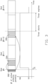
- the timer for antenna panel status may start at different time points, as shown in Figs. 3 and 4 .
- Fig. 3 is a schematic diagram illustrating a timeline of the antenna panel status of a wireless communication device (e.g., a UE), in accordance with example implementations of the present disclosure.
- the timer for antenna panel status may start at the first symbol after the end of a PUCCH.
- the UE receives an indicator for antenna panel status via a DCI message which is transmitted over a PDCCH 302.
- the UE may further receive a PDSCH 304 which is scheduled by the PDCCH 302 in the same slot #n.
- the indicator for antenna panel status may indicate to the UE to switch from a power saving mode (in which there are only N1 antenna panel(s) is turned on) to a normal power consumption mode (in which there are N2 antenna panels are turned on, where N2 is greater than N1).
- a time gap 31 between the time the UE receives the indicator for antenna panel status from the PDCCH 302 and the time the UE actually turns on the N2 antenna panels.
- the time gap 31 may reflect the time required for the UE to turn on the antenna panel(s).
- the time gap 31 may be deemed as the leading time for beam switching of the UE.
- the UE may start the timer at the first symbol after the last symbol of a PUCCH 306 monitor occasion. Similar to the implementations provided with reference to Fig. 2 , before the timer expires, the BS may assume that the UE may keep the antenna panel status indicated by the PDCCH 302, or applied for the PDSCH 304. Once the timer expires, the BS may assume that the UE may return to the power saving mode. As shown in Fig. 3 , in the slot #n+4, after the timer expires, the UE may turn off (N2-N1) antenna panels to go back to the power saving mode.
- the indicator for antenna panel status may indicate to the UE to switch from a power saving mode (in which there are only N1 antenna panel(s) is turned on) to a normal power consumption mode (in which there are N2 antenna panels are turned on, where N2 is greater than N1).
- a time gap 41 between the time the UE receives the indicator for antenna panel status from the PDCCH 402 and the time the UE actually turns on the N2 antenna panels.
- the time gap 41 may reflect the time required for the UE to turn on the antenna panel(s).
- the time gap 41 may be deemed as the leading time for beam switching of the UE.
- the timer for antenna panel status may count based on an absolute time unit (e.g., ms), a time slot, a subframe, or an OFDM symbol.
- an absolute time unit e.g., ms
- the numerology of the time unit may be determined based on the PDCCH which carries the scheduling information, or based on the PDSCH/RSs/ PUSCH/PUCCH which is scheduled by the PDCCH.
- the timer for antenna panel status may be an optional feature for the UE.
- the BS may decide whether to configure the timer to the UE based on the UE's capability.
- the UE may not automatically switch the antenna panel status (e.g., return to the power saving mode automatically).
- the UE may follow the most recently received indicator for antenna panels status (e.g., contained in a DCI message, a MAC-CE massage, or an RRC configuration) from the BS to determine the antenna panels status, until the UE sends a request to the BS and/or receives another indicator for antenna panels status from the BS.
- the BS may not configure the UE with the timer for antenna panel status. In such a case, if the BS does not receive a response to the indicator for antenna panel status from the UE, the BS may assume that the UE is in the power saving mode. Hence, the BS may assume that a longer leading time may be adopted by the UE, and the BS may determine a scheduling offset value for the UE based on this assumption.
- Some implementations of the present disclosure are described herein for determining the scheduling offset values and the leading time values for different antenna panel statuses.
- leading time value there is only one leading time value for each DL/LTL channel/RSs reception/transmission.
- a leading time value may be defined by the UE's capability for example.
- the above-mentioned mechanism may not be suitable for a situation where the UE needs a longer leading time for beam switching.
- the BS may configure the UE with a scheduling offset that is long enough to fulfill various leading times of different antenna panel statuses, such a configuration may cause some scheduling restrictions (e.g., because the UE may not always need to use a long leading time).
- some techniques are provided to improve scheduling flexibility and performance of beam switching.
- all DL/UL channel/RSs may be configured with one or more additional scheduling/triggering offset values for the situations where the UE may need to apply a long leading time value for beam switching, such as a PDSCH scheduling offset, a CSI-RS resource reception, a PUSCH transmission, and an SRS antenna switch.
- a PDSCH scheduling offset such as a PDSCH scheduling offset, a CSI-RS resource reception, a PUSCH transmission, and an SRS antenna switch.
- multiple scheduling offset values may be predefined for the UE (e.g., based on the 3GPP technical specification) or contained in the RRC configuration.
- the UE may apply one of the scheduling offset values based on the indicator for antenna panels status received from the BS. For example, the UE may apply a first scheduling offset value for a normal leading time case (e.g., in which the UE may not require to turn on an antenna panel, or only need to turn N1 antenna panel(s)), and apply a second scheduling offset value for a long leading time case (e.g., in which UE may need to turn on all of the antenna panels, or need to turn N2 antenna panels, where N2 is greater than N1).
- a normal leading time case e.g., in which the UE may not require to turn on an antenna panel, or only need to turn N1 antenna panel(s)
- a second scheduling offset value for a long leading time case e.g., in which UE may need to turn on all of the antenna panels, or need to turn N
- the UE may receive a plurality of scheduling offset values (e.g., including the first scheduling offset value and the second scheduling offset value) from the BS.
- Each of the scheduling offset values may be used for indicating a time duration counting from an end of a PDCCH to a beginning of a PDSCH.
- the UE may receive a first DCI message for setting the antenna panel status to a first antenna panel status.
- the UE may apply the first scheduling offset value to receive first information on a DL channel (e.g., a PDSCH) scheduled by the first DCI message.
- the UE may further receive a second DCI message for switching the antenna panel status from the first antenna panel status to a second antenna panel status.
- the second DCI message may include an indicator for antenna panel status information.
- the UE may apply the second scheduling offset value to receive second information on a second DL channel (e.g., another PDSCH) scheduled by the second DCI message.
- a second DL channel e.g., another PDSCH
- each DL/LTL channel/RS may have its corresponding scheduling offset value.
- the RRC configuration may include two scheduling offset values: one leading time value may be indicated as X1 slot(s) (e.g., one slot) used for a normal leading time case, and another leading time value may be indicated as X2 slots (e.g., three slots) used for a long leading time case, where X2 is greater than X1.
- the UE may select one of these scheduling offset values based on the indicator for antenna panel status received from the BS.
- the RRC configuration may include two scheduling offset values (e.g., the K0 parameters/values in the pdsch-TimeDomainResourceAllocationList IE).
- one scheduling offset value (K0) may be indicated as X1 slot(s) for the normal leading time case
- another scheduling offset value (K0) may be indicated as X2 slots for the long leading time case.
- the UE may select one of the scheduling offset values based on the indicator for antenna panel status.
- the UE may receive a scheduling offset value from the BS.
- the scheduling offset value may include at least one of a K0 parameter/value for a DL channel (e.g., a PDSCH) and a K2 parameter/value for a UL channel (e.g., a PUSCH). If the time duration indicated by the scheduling offset value is less than the leading time duration indicated by a selected leading time value, the UE may further determine that the scheduling offset value is invalid.
- all of the DL/UL channels/RSs may be configured with an additional leading time value for a beam switch case (e.g., a PDSCH scheduling offset, a CSI-RS resource reception, a PUSCH transmission or an SRS antenna switch).
- a beam switch case e.g., a PDSCH scheduling offset, a CSI-RS resource reception, a PUSCH transmission or an SRS antenna switch.
- UE may be configured by the BS to enable the power saving mode via an indicator for antenna panel status.
- Fig. 9 is an example data structure for an indicator for antenna panel status, in accordance with example implementations of the present disclosure.
- an indicator for antenna panel status 902 includes a power saving mode IE which is set as "true" to indicate to the UE to enable the power saving mode.
- the parameter values, data formats, and configurations provided herein are for illustrative purposes only, and not intended to limit the scope of the present invention.
- the number of slots for each K0 value (e.g., the normal K0 value or the long K0 value) may be different for different numerologies.
- the UE may apply a normal K0 value when the UE does not need to further turn on an antenna panel in response to the indicator for antenna panel status from the BS, and may apply a long K0 value when the UE needs to turn on at least one antenna panel in response to the indicator for antenna panel status.
- the UE may refer to the K0 configuration in Table 2 to apply a normal K0 value (e.g., 0 slot) contained in the row entry which is indexed by "1" and associated with the TCI state #1.
- the normal K0 value e.g., 0 slot
- the UE is expected to receive the PDSCH 1004 in the same slot as the PDCCH 1002, as shown in Fig. 10A .
- the UE may receive and decode a third DCI message DCI_3 which is transmitted over a PDCCH 1014 in the slot #m+7.
- the third DCI message DCI_3 may indicate to the UE to apply the same TCI state #64 as indicated in second DCI message DCI_2 for a scheduling PDSCH 1016.
- the TCI state #64 may indicate to the UE to receive the scheduling PDSCH 1016 in the normal power consumption mode, the UE has already operated in the normal power consumption mode before receiving the third DCI message DCI_3.
- the UE does not need to further turn on an antenna panel at this moment, and the UE may apply the normal K0 value (e.g., 0 slot) to determine when to receive the PDSCH 1016 (e.g., in the same slot #m+7 as the PDCCH 1014).
- the UE may transmit a HARQ-ACK over a PUCCH 1018 in the slot #k based on the ARI contained in the third DCI message DCI_3, as shown in Fig. 10B .
- the UE may be further configured with a timer for antenna panel status in addition to the multiple sets of parameters configured in action 702 of Fig. 7 .
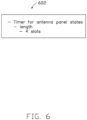
- the configuration of the timer for antenna panel status may be, but not limited to, the configuration 602 in Fig. 6 .
- the numerology of the timer for antenna panel status may be determined based on the scheduling PDSCH of the active DL BWP.
- Figs. 11A and 11B are schematic diagrams illustrating timelines of the antenna panel status of a wireless communication device (e.g., a UE), in accordance with example implementations of the present disclosure. It should be noted that the timeline of Fig. 11B is continued from that of Fig. 11A .
- the total number of turned-on/active antenna panels at the UE is N1 when the power saving mode is enabled and is N2 when the power saving mode is disabled, where N1 is less than N2.
- N1 may be "1" and N2 may be the number of the antenna panels the UE has.
- the UE may receive and decode a first DCI message DCI_1 which is transmitted over a PDCCH 1102 in the slot #n.
- the first DCI message DCI_1 may indicate to the UE to apply a particular TCI state (e.g., the TCI state #1 contained in the TCI state configuration 802 in Fig. 8 ) for a scheduling PDSCH 1104.
- a particular TCI state e.g., the TCI state #1 contained in the TCI state configuration 802 in Fig. 8
- the UE may follow the TCI state #1 to monitor the scheduling PDSCH 1004 in the power saving mode.
- the UE may receive a second DCI message DCI_2 which is transmitted over a PDCCH 1506 in the slot #n+1.
- the second DCI message DCI_2 may contain a CSI request for triggering an aperiodic CSI report.
- the CSI request for triggering the CSI-RS resource may be indicated by the BS, through the QCL information associated with the CSI-RS resource, to be received by the multiple antenna panels at the UE.
- the UE may apply a normal triggering offset value when the UE does not need to further turn on an antenna panel in response to the indicator for antenna panel status obtained from the BS, and apply a long triggering offset value when the UE needs to turn on at least one antenna panel in response to the indicator for antenna panel status received from the BS.
- the UE may apply a long triggering offset value (e.g., aperiodicTriggeringOffset) for the CSI request to switch from the power saving mode to the normal power consumption mode.
- the BS may transmit the CSI-RS resource in the slot #n+7, which is the sixth time slot after the slot #n+1.
- the UE may further receive a third DCI message DCI_3 which is transmitted over a PDCCH 1510 in the slot #m.
- the third DCI message DCI_3 may contain a CSI request for triggering an aperiodic CSI report, and the CSI request may indicate the same aperiodic CSI-RS trigger state as indicated by the CSI request contained in the second DCI message DCI_2.
- the UE may be further configured with a timer for antenna panel status in addition to the multiple sets of parameters configured in action 1202 of Fig. 12 .
- the configuration of the timer for antenna panel status may be, but not limited to, the configuration 602 in Fig. 6 .
- the numerology of the timer for antenna panel status may be determined based on the scheduling PDSCH of the active DL BWP.
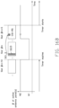
- Figs. 16A and 16B are schematic diagrams illustrating that different triggering offset values (e.g., K0 values) are applied for the changes in the antenna panel status of a wireless communication device (e.g., a UE), in accordance with example implementations of the present disclosure. It should be noted that Fig. 16B is continued from the Fig. 16A .
- the total number of turned-on/active antenna panels at the UE is N1 when the UE is in the power saving mode and is N2 when the UE is the normal power consumption mode, where N1 is less than N2.
- N1 may be "1" and N2 may be the number of the antenna panels the UE has.
- the timer may then expire at the end of the slot n+10, and the UE may switch from the normal power consumption mode to the power saving mode.
- the UE may then receive a third DCI message DCI_3 which is transmitted over a PDCCH 1610 in the slot #m, where m>n+10.
- the third DCI message DCI_3 may contain a CSI request for triggering an aperiodic CSI report, and the CSI request may indicate the same aperiodic CSI-RS trigger state as indicated by the second DCI message DCI_2.
- Example 3-1 An illustrative example (denoted as Example 3-1) will now be provided, where a UE may indicate its antenna panel status through at least one explicit bit in a CSI report.
- the UE may be configured with a periodic CSI report and the periodicity for the CSI report may be 20 slots.
- the UE may be configured with a timer for antenna panel status.
- the configuration of the timer for antenna panel status may be, but not limited to, the configuration 602 shown in Fig. 6 .
- the numerology of the timer for antenna panel status may be determined based on the scheduling PDSCH of active DL BWP.
- Example 4-1 An illustrative example (denoted as Example 4-1) will now be provided, where the antenna panel status may be switched based on a DRX operation.
- Fig. 18 is a flowchart for a method for determining the antenna panel status of a wireless communication device (e.g., a UE) based on a DRX operation, in accordance with example implementations of the present disclosure.
- the UE may be configured with a DRX inactivity timer by the BS.
- the UE may switch the antenna panel status based on the DRX inactivity timer.
- the UE may be configured with a DRX period and a timer for antenna panel status.
- the BS may indicate to the UE to operate in the normal power consumption mode, as shown in Fig. 19 .
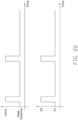
- Fig. 20 is a schematic diagram illustrating a timeline of the antenna panel status of a wireless communication device (e.g., a UE) and a timing diagram of a DRX cycle, in accordance with example implementations of the present disclosure.
- the timer for antenna panel status may have the same operation as the DRX inactivity timer.
- the total number of turned-on/active antenna panels at the UE is N1 when the UE is in the power saving mode and is N2 when the UE is the normal power consumption mode, where N1 is less than N2.
- the UE may receive a DCI message in the slot #n at which the UE is in a DRX on-duration.
- the UE may start both the DRX inactivity timer and the timer for antenna panel status, if the DCI message is used for indicating to the UE to operate in the normal power consumption mode.
- the DRX inactivity timer may follow the timer for antenna panel status to stop/expire at the same timing (e.g., at the beginning of the slot #n+4).
- the UE may enter a DRX off-duration and operate in the power saving mode at the same time.
- Fig. 21 is an example data structure indicating an RRC configuration for the UE, in accordance with example implementations of the present disclosure.
- an RRC configuration 2102 may include a DRX configuration and an antenna panel status configuration.
- the DRX configuration may be configured with a DRX inactivity timer for 2 ms and a DRX cycle of 50 ms.
- the antenna panel status configuration may indicate that the power saving mode is to be disabled (e.g., with a "False" value).
- the UE may at first operate in the normal power consumption mode based on the most recently received BS instruction (e.g., received through an RRC configuration, a MAC-CE message or a DCI message). If the UE does not receive a PDCCH in the DRX on-duration (at which the UE is in an active state), the UE may then switch to the power saving mode after the UE enters the DRX off-duration (at which the UE is in an inactive/sleep state).
- the BS instruction e.g., received through an RRC configuration, a MAC-CE message or a DCI message.
- a wireless communication device e.g., a UE may maintain a plurality of leading time values, wherein the plurality of leading time values may indicate a plurality of leading time durations.
- the wireless communication device may receive an indicator for antenna panel status information from a BS.
- Fig. 24 is a block diagram illustrating a node for wireless communication, in accordance with various aspects of the present application.
- a node 2400 may include a transceiver 2420, a processor 2428, a memory 2434, one or more presentation components 2438, and at least one antenna 2436.
- the node 2400 may also include an RF spectrum band module, a BS communications module, a network communications module, and a system communications management module, Input/Output (I/O) ports, I/O components, and power supply (not explicitly shown in Fig. 24 ).
- I/O Input/Output
- the node 2400 may be a UE or a BS that performs various functions described herein, for example, with reference to Figs. 1 through 23 .
- the transceiver 2420 having a transmitter 2422 (e.g., transmitting/transmission circuitry) and a receiver 2424 (e.g., receiving/reception circuitry) may be configured to transmit and/or receive time and/or frequency resource partitioning information.
- the transceiver 2420 may be configured to transmit in different types of subframes and slots including, but not limited to, usable, non-usable and flexibly usable subframes and slot formats.
- the transceiver 2420 may be configured to receive data and control channels.
- the node 2400 may include a variety of computer-readable media.
- Computer-readable media may be any available media that may be accessed by the node 2400 and include both volatile and non-volatile media, removable and non-removable media.
- Computer-readable media may comprise computer storage media and communication media.
- Computer storage media includes both volatile and non-volatile, removable and non-removable media implemented in any method or technology for storage of information such as computer-readable instructions, data structures, program modules or other data.
- Computer storage media includes RAM, ROM, EEPROM, flash memory or other memory technology, CD-ROM, Digital Versatile Disks (DVD) or other optical disk storage, magnetic cassettes, magnetic tape, magnetic disk storage or other magnetic storage devices.
- Computer storage media does not comprise a propagated data signal.
- Communication media typically embodies computer-readable instructions, data structures, program modules or other data in a modulated data signal such as a carrier wave or other transport mechanism and includes any information delivery media.
- modulated data signal means a signal that has one or more of its characteristics set or changed in such a manner as to encode information in the signal.
- communication media includes wired media such as a wired network or direct-wired connection, and wireless media such as acoustic, RF, infrared and other wireless media. Combinations of any of the above should also be included within the scope of computer-readable media.
- the memory 2434 may include computer-storage media in the form of volatile and/or non-volatile memory.
- the memory 2434 may be removable, non-removable, or a combination thereof.
- Example memory includes solid-state memory, hard drives, optical-disc drives, and etc.
- the memory 2434 may store computer-readable, computer-executable instructions 2432 (e.g., software codes) that are configured to, when executed, cause the processor 2428 to perform various functions described herein, for example, with reference to Figs. 1 through 23 .
- the instructions 2432 may not be directly executable by the processor 2428 but be configured to cause the node 2400 (e.g., when compiled and executed) to perform various functions described herein.
- the processor 2428 may include an intelligent hardware device, e.g., a Central Processing Unit (CPU), a microcontroller, an ASIC, and etc.
- the processor 2428 may include memory.
- the processor 2428 may process the data 2430 and the instructions 2432 received from the memory 2434, and information through the transceiver 2420, the base band communications module, and/or the network communications module.
- the processor 2428 may also process information to be sent to the transceiver 2420 for transmission through the antenna 2436, to the network communications module for transmission to a core network.
- presentation components 2438 presents data indications to a person or other device.
- presentation components 2438 may include a display device, speaker, printing component, vibrating component, etc.
Landscapes
- Engineering & Computer Science (AREA)
- Computer Networks & Wireless Communication (AREA)
- Signal Processing (AREA)
- Computer Security & Cryptography (AREA)
- Mobile Radio Communication Systems (AREA)
- Quality & Reliability (AREA)
- Physics & Mathematics (AREA)
- Electromagnetism (AREA)
Claims (2)
- Procédé de fonctionnement d'une pluralité de panneaux d'antenne, le procédé comprenant :le maintien, par un dispositif de communication sans fil (100), d'une pluralité de valeurs de temps de délai, la pluralité de valeurs de temps de délai indiquant une pluralité de durées de temps de délai, dans lequel un temps de délai est un laps de temps entre un temps auquel le dispositif de communication sans fil (100) reçoit une commande qui entraîne au moins un changement de l'état de faisceau RX et/ou de panneau d'antenne et un temps auquel l'au moins un changement se produit réellement ;la réception, par le dispositif de communication sans fil (100), d'un indicateur pour des informations d'état de panneau d'antenne en provenance d'une station de base, « Base Station » BS, dans lequel les informations d'état de panneau d'antenne contiennent des informations concernant la quantité de panneaux d'antenne au niveau du dispositif de communication sans fil (100) qui sont utilisés pour réaliser une réception et/ou une transmission de données d'un canal ou d'un signal de référence, ou concernant la quantité de panneaux d'antenne au niveau du dispositif de communication sans fil (100) qui sont utilisés dans un laps de temps particulier ;l'application, par le dispositif de communication sans fil (100), d'une de la pluralité de valeurs de temps de délai pour allumer ou éteindre au moins un de la pluralité de panneaux d'antenne sur la base de l'indicateur pour des informations d'état de panneau d'antenne ;la réception, par le dispositif de communication sans fil (100), d'une valeur de décalage de planification en provenance de la BS, la valeur de décalage de planification comprenant au moins un d'un paramètre K0 pour un canal de liaison descendante, « DownLink » DL, pour déterminer un décalage de réception de canal partagé de liaison descendante physique, « Physical Downlink Shared Channel » PDSCH, et d'un paramètre K2 pour un canal de liaison montante, « UpLink » UL, pour déterminer un décalage de transmission de canal partagé de liaison montante physique, « Physical Uplink Shared Channel » PUSCH,dans lequel le paramètre K0 indique un nombre de créneaux pour un cas de temps de délai normal dans lequel le dispositif de communication sans fil n'a pas besoin d'allumer un de ses panneaux d'antenne, ou a besoin seulement d'allumer M1 panneaux d'antenne, etdans lequel le paramètre K2 indique un nombre de créneaux pour un cas de temps de délai long dans lequel le dispositif de communication sans fil a besoin d'allumer la totalité de ses panneaux d'antenne, ou a besoin d'allumer M2 panneaux d'antenne, où M2 est supérieur à M1 ; etla détermination, par le dispositif de communication sans fil (100), que la valeur de décalage de planification est invalide, lorsqu'une durée de temps indiquée par la valeur de décalage de planification est inférieure à la durée de temps de délai indiquée par la valeur de temps de délai appliquée, dans lequel, lorsque la valeur de décalage de planification est invalide, le dispositif de communication sans fil (100) n'est pas capable de transmettre et/ou de recevoir un canal de DL ou de UL ou un signal de référence.
- Dispositif de communication sans fil (100), comprenant :une pluralité de panneaux d'antenne ;un processeur couplé à la pluralité de panneaux d'antenne et configuré pour réaliser le procédé de la revendication 1.
Applications Claiming Priority (2)
| Application Number | Priority Date | Filing Date | Title |
|---|---|---|---|
| US201862699465P | 2018-07-17 | 2018-07-17 | |
| PCT/CN2019/096060 WO2020015614A1 (fr) | 2018-07-17 | 2019-07-16 | Procédés et appareils de fonctionnement de multiples panneaux d'antenne |
Publications (4)
| Publication Number | Publication Date |
|---|---|
| EP3824562A1 EP3824562A1 (fr) | 2021-05-26 |
| EP3824562A4 EP3824562A4 (fr) | 2022-05-18 |
| EP3824562C0 EP3824562C0 (fr) | 2025-07-02 |
| EP3824562B1 true EP3824562B1 (fr) | 2025-07-02 |
Family
ID=69161231
Family Applications (1)
| Application Number | Title | Priority Date | Filing Date |
|---|---|---|---|
| EP19838487.7A Active EP3824562B1 (fr) | 2018-07-17 | 2019-07-16 | Procédés et appareils de fonctionnement de multiples panneaux d'antenne |
Country Status (4)
| Country | Link |
|---|---|
| US (1) | US10972972B2 (fr) |
| EP (1) | EP3824562B1 (fr) |
| CN (1) | CN112425198A (fr) |
| WO (1) | WO2020015614A1 (fr) |
Families Citing this family (75)
| Publication number | Priority date | Publication date | Assignee | Title |
|---|---|---|---|---|
| CN110536456B (zh) * | 2018-05-25 | 2022-03-25 | 成都华为技术有限公司 | 通信方法、终端设备和网络设备 |
| US11533123B2 (en) * | 2018-07-20 | 2022-12-20 | Qualcomm Incorporated | Cross-carrier sounding with aperiodic channel state information reference signals (CSI-RS) |
| EP3836417A4 (fr) * | 2018-08-10 | 2022-07-06 | Beijing Xiaomi Mobile Software Co., Ltd. | Procédé et appareil de réglage de module d'antenne, et support de stockage |
| US11166238B2 (en) * | 2018-09-13 | 2021-11-02 | Qualcomm Incorporated | Methods and apparatus for supporting multiple power and spectrum efficient modes for power saving |
| US11522274B2 (en) * | 2018-09-28 | 2022-12-06 | Nokia Technologies Oy | Facilitating user equipment beamforming control |
| CN114900880A (zh) * | 2018-12-11 | 2022-08-12 | 华为技术有限公司 | 同步信号块的发送、接收方法及装置 |
| CN111278089B (zh) * | 2019-01-08 | 2021-10-12 | 维沃移动通信有限公司 | 一种天线面板控制方法、终端设备及网络侧设备 |
| CN117858278A (zh) * | 2019-01-10 | 2024-04-09 | 北京三星通信技术研究有限公司 | 一种物理下行控制信道的监听方法、终端设备及存储介质 |
| US11647459B2 (en) * | 2019-02-11 | 2023-05-09 | Qualcomm Incorporated | Network control and signaling for power circuitry configuration |
| CA3072491A1 (fr) | 2019-02-14 | 2020-08-14 | Comcast Cable Communications, Llc | Gestion de la transmission/reception dans une communication sans fil |
| US11864109B2 (en) * | 2019-03-04 | 2024-01-02 | Qualcomm Incorporated | Wake-up signal operation for multiple transmission and reception points |
| US11425650B2 (en) * | 2019-04-26 | 2022-08-23 | Qualcomm Incorporated | Signaling for multi-panel UE activation |
| HUE070008T2 (hu) * | 2019-05-02 | 2025-05-28 | Nokia Technologies Oy | A PDCCH felügyelet meghatározása a bekapcsolási idõ alatt energiatakarékos üzemmódban |
| US10826568B1 (en) * | 2019-05-03 | 2020-11-03 | Qualcomm Incorporated | Simultaneous multiple default beams |
| US11627562B2 (en) * | 2019-05-10 | 2023-04-11 | Qualcomm Incorporated | Multi-panel activation/deactivation status reporting |
| US11457350B2 (en) | 2019-05-10 | 2022-09-27 | Qualcomm Incorporated | Signaling user equipment multi-panel capability |
| US20200374804A1 (en) * | 2019-05-25 | 2020-11-26 | Qualcomm Incorporated | High efficiency transmission mode support |
| CN112073129B (zh) * | 2019-06-10 | 2022-03-29 | 成都华为技术有限公司 | 确定天线面板状态的方法和装置 |
| CN112086750B (zh) * | 2019-06-13 | 2022-02-08 | 中国电信股份有限公司 | 终端天线面板工作状态的方法、系统以及存储介质 |
| WO2021002609A1 (fr) * | 2019-07-02 | 2021-01-07 | 엘지전자 주식회사 | Dispositif de communication et procédé pour effectuer une mesure par l'intermédiaire de multiples panneaux d'antenne |
| CN110537388B (zh) * | 2019-07-16 | 2023-09-29 | 北京小米移动软件有限公司 | 数据传输方法、装置及存储介质 |
| CN112312574B (zh) * | 2019-08-02 | 2025-04-08 | 华为技术有限公司 | 一种通信传输的方法 |
| US11451979B2 (en) * | 2019-08-14 | 2022-09-20 | At&T Intellectual Property I, L.P. | Device testing optimization for 5G or other next generation network |
| CN112398520B (zh) * | 2019-08-16 | 2022-05-13 | 华为技术有限公司 | 发送信道状态信息的方法和相关设备 |
| US12143227B2 (en) * | 2019-11-07 | 2024-11-12 | Sharp Kabushiki Kaisha | User equipments, base stations, and methods |
| CN114641940B (zh) * | 2019-11-12 | 2024-01-12 | 三星电子株式会社 | 毫米波频段中多模式装置的发送和接收方法 |
| US11510212B2 (en) * | 2019-11-25 | 2022-11-22 | Samsung Electronics Co., Ltd. | Method and apparatus for beam management for mobility |
| WO2021109085A1 (fr) * | 2019-12-05 | 2021-06-10 | 北京小米移动软件有限公司 | Procédé et appareil d'attribution d'unités de ressources de communication, dispositif de communication et support de stockage |
| WO2021138882A1 (fr) * | 2020-01-10 | 2021-07-15 | Qualcomm Incorporated | Indication robuste de faisceau rapide basée sur dci |
| EP4094369A1 (fr) * | 2020-01-21 | 2022-11-30 | Telefonaktiebolaget LM Ericsson (publ) | Transmission de ressources de signal de référence et configuration associée |
| US11831383B2 (en) | 2020-01-27 | 2023-11-28 | Qualcomm Incorporated | Beam failure recovery assistance in upper band millimeter wave wireless communications |
| US11856570B2 (en) * | 2020-01-27 | 2023-12-26 | Qualcomm Incorporated | Dynamic mixed mode beam correspondence in upper millimeter wave bands |
| US12407385B2 (en) | 2020-01-27 | 2025-09-02 | Qualcomm Incorporated | Signaling of beam correlation across millimeter wave frequency bands |
| CN115004574B (zh) | 2020-01-27 | 2025-03-11 | 高通股份有限公司 | 频带中的天线组选择和指示 |
| US12401403B2 (en) | 2020-01-27 | 2025-08-26 | Qualcomm Incorporated | Antenna group-specific parameter configuration in millimeter wave communications |
| US12531626B2 (en) | 2020-01-27 | 2026-01-20 | Qualcomm Incorporated | Asymmetric uplink-downlink beam training in frequency bands |
| EP4101105B1 (fr) * | 2020-02-04 | 2026-03-18 | Qualcomm Incorporated | Indication dynamique de décalage de voie de signal de référence de sondage apériodique |
| CN113258970B (zh) * | 2020-02-10 | 2023-10-03 | 大唐移动通信设备有限公司 | 确定天线阵面切换的方法、终端及基站 |
| US12374787B2 (en) | 2020-02-11 | 2025-07-29 | Qualcomm Incorporated | Adjusting communications operations for changes to configurations for quasi co-location and number of antenna elements |
| WO2021176725A1 (fr) * | 2020-03-06 | 2021-09-10 | 株式会社Nttドコモ | Terminal, procédé de communication sans fil, et station de base |
| CN115336301B (zh) * | 2020-03-26 | 2025-05-13 | 株式会社Ntt都科摩 | 终端、无线通信方法以及基站 |
| WO2021192171A1 (fr) * | 2020-03-26 | 2021-09-30 | 株式会社Nttドコモ | Terminal, procédé de communication sans fil, et station de base |
| CN115398943B (zh) * | 2020-04-02 | 2025-04-22 | 株式会社Ntt都科摩 | 终端、无线通信方法以及基站 |
| US20230246681A1 (en) * | 2020-04-09 | 2023-08-03 | Sony Group Corporation | Communication device, communication control method, and communication system |
| US11546902B2 (en) * | 2020-04-13 | 2023-01-03 | Samsung Electronics Co., Ltd. | Method and apparatus for dynamic multi-beam operations |
| CN115606111A (zh) * | 2020-05-15 | 2023-01-13 | 苹果公司(Us) | 无线电资源管理信号接收 |
| US12490130B2 (en) * | 2020-07-02 | 2025-12-02 | Qualcomm Incorporated | Channel state information (CSI) signaling for multiple report metrics |
| US11770812B2 (en) * | 2020-07-08 | 2023-09-26 | Samsung Electronics Co. , Ltd. | Methods and apparatuses for physical layer beam indications |
| CN113973369B (zh) * | 2020-07-22 | 2026-03-06 | 维沃移动通信有限公司 | 获取、指示通信资源的方法、装置及电子设备 |
| WO2022027012A1 (fr) * | 2020-07-27 | 2022-02-03 | Idac Holdings, Inc. | Procédés, architectures, appareils et systèmes de détermination dynamique de temps de traitement |
| CN111885689B (zh) * | 2020-07-30 | 2024-04-19 | 广东小天才科技有限公司 | 一种天线控制方法、装置及终端设备 |
| CN116097574B (zh) | 2020-08-05 | 2025-05-06 | 苹果公司 | 用于为用户装备(ue)在非对称上行链路(ul)天线面板中进行选择的系统和方法 |
| CN116097572B (zh) * | 2020-08-05 | 2025-05-06 | 苹果公司 | 用于为在用户装备(ue)处选择非对称上行链路(ul)天线面板提供网络指示的系统和方法 |
| WO2022027379A1 (fr) * | 2020-08-05 | 2022-02-10 | Apple Inc. | Ordonnancement d'un équipement d'utilisateur en tant que partie d'un groupe |
| WO2022031450A1 (fr) * | 2020-08-06 | 2022-02-10 | Mediatek Singapore Pte. Ltd. | Procédé et appareil pour un équipement utilisateur ayant de multiples panneaux |
| WO2022032596A1 (fr) | 2020-08-13 | 2022-02-17 | 华为技术有限公司 | Procédé, appareil et système de gestion de panneau d'antenne |
| JP7470317B2 (ja) | 2020-08-26 | 2024-04-18 | オフィノ, エルエルシー | 制御チャネルの繰り返しにおけるデフォルトルール |
| WO2022048437A1 (fr) | 2020-09-01 | 2022-03-10 | Qualcomm Incorporated | Demandes de signal de référence initiées par un équipement utilisateur (ue) |
| WO2022047602A1 (fr) * | 2020-09-01 | 2022-03-10 | Qualcomm Incorporated | Demandes de signal de référence initiées par un équipement d'utilisateur (ue) |
| US11705947B2 (en) * | 2020-10-12 | 2023-07-18 | Qualcomm Incorporated | Techniques for activating or deactivating antenna panels at a user equipment |
| CN116803042A (zh) * | 2021-01-04 | 2023-09-22 | 鸿颖创新有限公司 | 用于为用户设备配置tci状态的方法和使用同样方法的用户设备 |
| KR20230128273A (ko) * | 2021-01-07 | 2023-09-04 | 엘지전자 주식회사 | 무선 통신 시스템에서 상향링크 송수신 방법 및 장치 |
| EP4277147A4 (fr) * | 2021-01-11 | 2024-12-11 | LG Electronics Inc. | Procédé et dispositif de transmission et de réception de signal sur la base d'un paramètre spatial dans un système de communication sans fil |
| US12477538B2 (en) | 2021-01-12 | 2025-11-18 | Qualcomm Incorporated | Techniques for timing relationships for physical downlink control channel repetition |
| US12532342B2 (en) * | 2021-03-15 | 2026-01-20 | Samsung Electronics Co., Ltd. | Method and apparatus for aperiodic CSI measurement and reporting |
| US11582631B2 (en) | 2021-04-14 | 2023-02-14 | Nokia Technologies Oy | User equipment indication for adaptive scheduling restrictions |
| WO2023081559A1 (fr) * | 2021-11-05 | 2023-05-11 | Qualcomm Incorporated | Configuration de panneau d'antenne après rapport |
| US12127012B2 (en) | 2021-11-05 | 2024-10-22 | Qualcomm Incorporated | Antenna panel configuration after reporting |
| US11943715B2 (en) * | 2021-11-18 | 2024-03-26 | Qualcomm Incorporated | Techniques for configuring use of an energy saving mode |
| US11848730B2 (en) * | 2021-12-16 | 2023-12-19 | Qualcomm Incorporated | Methods for feedback of metrics associated with reduced capability antenna modules in millimeter wave systems |
| US12267843B2 (en) * | 2022-02-04 | 2025-04-01 | Qualcomm Incorporated | Default beam for cross-carrier scheduling with unified transmission configuration indicator |
| WO2023209984A1 (fr) * | 2022-04-28 | 2023-11-02 | 株式会社Nttドコモ | Terminal, procédé de communication sans fil et station de base |
| US12609726B2 (en) | 2022-07-13 | 2026-04-21 | Qualcomm Incorporated | Antenna side combining or antenna side selection in an L-shaped antenna module |
| US12549239B2 (en) * | 2022-09-30 | 2026-02-10 | Qualcomm Incorporated | Capability for using antenna configuration set for uplink beam |
| CN119675834A (zh) * | 2023-09-12 | 2025-03-21 | 伟光有限公司 | 控制信道监听方法、装置、芯片、设备及存储介质 |
Citations (1)
| Publication number | Priority date | Publication date | Assignee | Title |
|---|---|---|---|---|
| US20180145742A1 (en) * | 2016-11-23 | 2018-05-24 | Qualcomm Incorporated | Techniques and apparatuses for switching between a single antenna subarray operation and a multiple antenna subarray operation for different traffic types |
Family Cites Families (12)
| Publication number | Priority date | Publication date | Assignee | Title |
|---|---|---|---|---|
| US8611829B2 (en) * | 2011-08-09 | 2013-12-17 | Motorola Mobility Llc | Tunable filter feedback to control antenna switch diversity |
| WO2016029485A1 (fr) | 2014-08-30 | 2016-03-03 | 华为技术有限公司 | Procédé et dispositif de transmission et de réception d'informations d'antenne |
| US10666346B2 (en) | 2015-11-11 | 2020-05-26 | Telefonaktiebolaget Lm Ericsson (Publ) | Network node, wireless device, and methods for beam management |
| US11006429B2 (en) * | 2016-05-04 | 2021-05-11 | Apple Inc. | Antenna panel switching and beam indication |
| WO2018031082A1 (fr) | 2016-08-11 | 2018-02-15 | Intel Corporation | Livre de codes de transformée de fourier discrète (tfd) et schémas de rétroaction |
| EP4243325B1 (fr) * | 2017-11-15 | 2026-02-18 | InterDigital Patent Holdings, Inc. | Gestion de faisceau dans un réseau sans fil |
| CN112075029B (zh) * | 2018-04-06 | 2022-08-16 | 诺基亚技术有限公司 | 用于多面板ue的波束指示 |
| CN112314009B (zh) * | 2018-05-14 | 2024-06-21 | 诺基亚技术有限公司 | 促进多面板用户设备的不连续接收 |
| CN110868231B (zh) * | 2018-08-10 | 2021-08-13 | 华为技术有限公司 | 管理天线面板的方法、网络设备和终端设备 |
| EP3909295A4 (fr) * | 2019-01-11 | 2022-11-30 | FG Innovation Company Limited | Planification d'un état d'économie d'énergie dans des réseaux sans fil de nouvelle génération |
| US11943030B2 (en) * | 2019-05-09 | 2024-03-26 | FG Innovation Company Limited | Method and apparatus for antenna panel control |
| US11979211B2 (en) * | 2019-05-14 | 2024-05-07 | Nokia Solutions And Networks Oy | Managing multiple antenna panels for user equipment within wireless networks |
-
2019
- 2019-07-15 US US16/511,170 patent/US10972972B2/en active Active
- 2019-07-16 WO PCT/CN2019/096060 patent/WO2020015614A1/fr not_active Ceased
- 2019-07-16 CN CN201980047644.7A patent/CN112425198A/zh active Pending
- 2019-07-16 EP EP19838487.7A patent/EP3824562B1/fr active Active
Patent Citations (1)
| Publication number | Priority date | Publication date | Assignee | Title |
|---|---|---|---|---|
| US20180145742A1 (en) * | 2016-11-23 | 2018-05-24 | Qualcomm Incorporated | Techniques and apparatuses for switching between a single antenna subarray operation and a multiple antenna subarray operation for different traffic types |
Also Published As
| Publication number | Publication date |
|---|---|
| US10972972B2 (en) | 2021-04-06 |
| EP3824562A1 (fr) | 2021-05-26 |
| EP3824562A4 (fr) | 2022-05-18 |
| EP3824562C0 (fr) | 2025-07-02 |
| US20200029274A1 (en) | 2020-01-23 |
| CN112425198A (zh) | 2021-02-26 |
| WO2020015614A1 (fr) | 2020-01-23 |
Similar Documents
| Publication | Publication Date | Title |
|---|---|---|
| EP3824562B1 (fr) | Procédés et appareils de fonctionnement de multiples panneaux d'antenne | |
| US11832186B2 (en) | Scheduling for power saving state in next generation wireless networks | |
| US11382076B2 (en) | Physical uplink control channel repetition in next generation wireless networks | |
| US12170959B2 (en) | Terminal power saving method, power saving apparatus, information sending method and apparatus, storage medium, and electronic device | |
| KR102943254B1 (ko) | 전력 절감 동작들을 위한 방법들 및 장치들 | |
| EP3780770B1 (fr) | Procédé de fonctionnement d'une partie de bande passante et équipement utilisateur l'utilisant | |
| TWI745189B (zh) | 針對部分頻寬切換操作之通訊方法及使用者裝置 | |
| US11943030B2 (en) | Method and apparatus for antenna panel control | |
| US12273751B2 (en) | Methods and apparatus for supporting common design of PDCCH skipping and search space set switching | |
| TW202046780A (zh) | 監測實體下行鏈路控制通道的方法及相關裝置 | |
| US12167369B2 (en) | Method and user equipment for resource selection approach adaptation | |
| KR102765596B1 (ko) | 무선 통신에서의 적응형 파라미터 구성 | |
| EP3874903B1 (fr) | Procédés et dispositifs pour une configuration de réception discontinue adaptative | |
| EP4151042A1 (fr) | Procédé et équipement d'utilisateur pour réaliser une communication de liaison latérale | |
| CA3143610C (fr) | Procede d'economie d'energie de terminal, appareil d'economie d'energie, procede et appareil d'envoi d'informations, support d'informations et dispositif electronique | |
| KR20250174377A (ko) | 무선 통신 시스템에서 에너지 세이빙을 위한 방법 및 장치 | |
| KR20250146639A (ko) | 통신 시스템에서 신호 모니터링의 방법 및 장치 | |
| CN121176103A (zh) | 接收下行链路信号的方法、用户设备、处理装置和存储介质及发送下行链路信号的方法和基站 |
Legal Events
| Date | Code | Title | Description |
|---|---|---|---|
| STAA | Information on the status of an ep patent application or granted ep patent |
Free format text: STATUS: THE INTERNATIONAL PUBLICATION HAS BEEN MADE |
|
| PUAI | Public reference made under article 153(3) epc to a published international application that has entered the european phase |
Free format text: ORIGINAL CODE: 0009012 |
|
| STAA | Information on the status of an ep patent application or granted ep patent |
Free format text: STATUS: REQUEST FOR EXAMINATION WAS MADE |
|
| 17P | Request for examination filed |
Effective date: 20210211 |
|
| AK | Designated contracting states |
Kind code of ref document: A1 Designated state(s): AL AT BE BG CH CY CZ DE DK EE ES FI FR GB GR HR HU IE IS IT LI LT LU LV MC MK MT NL NO PL PT RO RS SE SI SK SM TR |
|
| DAV | Request for validation of the european patent (deleted) | ||
| DAX | Request for extension of the european patent (deleted) | ||
| A4 | Supplementary search report drawn up and despatched |
Effective date: 20220419 |
|
| RIC1 | Information provided on ipc code assigned before grant |
Ipc: H04W 64/00 20090101ALI20220411BHEP Ipc: H01Q 21/00 20060101ALI20220411BHEP Ipc: H04B 7/04 20170101AFI20220411BHEP |
|
| STAA | Information on the status of an ep patent application or granted ep patent |
Free format text: STATUS: EXAMINATION IS IN PROGRESS |
|
| 17Q | First examination report despatched |
Effective date: 20230215 |
|
| RAP1 | Party data changed (applicant data changed or rights of an application transferred) |
Owner name: TOGAIL TECHNOLOGIES, LTD. |
|
| RAP1 | Party data changed (applicant data changed or rights of an application transferred) |
Owner name: NERA INNOVATIONS LTD. |
|
| GRAP | Despatch of communication of intention to grant a patent |
Free format text: ORIGINAL CODE: EPIDOSNIGR1 |
|
| STAA | Information on the status of an ep patent application or granted ep patent |
Free format text: STATUS: GRANT OF PATENT IS INTENDED |
|
| INTG | Intention to grant announced |
Effective date: 20250124 |
|
| GRAS | Grant fee paid |
Free format text: ORIGINAL CODE: EPIDOSNIGR3 |
|
| GRAA | (expected) grant |
Free format text: ORIGINAL CODE: 0009210 |
|
| STAA | Information on the status of an ep patent application or granted ep patent |
Free format text: STATUS: THE PATENT HAS BEEN GRANTED |
|
| AK | Designated contracting states |
Kind code of ref document: B1 Designated state(s): AL AT BE BG CH CY CZ DE DK EE ES FI FR GB GR HR HU IE IS IT LI LT LU LV MC MK MT NL NO PL PT RO RS SE SI SK SM TR |
|
| REG | Reference to a national code |
Ref country code: GB Ref legal event code: FG4D |
|
| REG | Reference to a national code |
Ref country code: CH Ref legal event code: EP |
|
| REG | Reference to a national code |
Ref country code: DE Ref legal event code: R096 Ref document number: 602019072060 Country of ref document: DE |
|
| REG | Reference to a national code |
Ref country code: IE Ref legal event code: FG4D |
|
| U01 | Request for unitary effect filed |
Effective date: 20250708 |
|
| U07 | Unitary effect registered |
Designated state(s): AT BE BG DE DK EE FI FR IT LT LU LV MT NL PT RO SE SI Effective date: 20250811 |
|
| U20 | Renewal fee for the european patent with unitary effect paid |
Year of fee payment: 7 Effective date: 20250923 |
|
| PG25 | Lapsed in a contracting state [announced via postgrant information from national office to epo] |
Ref country code: IS Free format text: LAPSE BECAUSE OF FAILURE TO SUBMIT A TRANSLATION OF THE DESCRIPTION OR TO PAY THE FEE WITHIN THE PRESCRIBED TIME-LIMIT Effective date: 20251102 |
|
| PG25 | Lapsed in a contracting state [announced via postgrant information from national office to epo] |
Ref country code: NO Free format text: LAPSE BECAUSE OF FAILURE TO SUBMIT A TRANSLATION OF THE DESCRIPTION OR TO PAY THE FEE WITHIN THE PRESCRIBED TIME-LIMIT Effective date: 20251002 |
|
| PG25 | Lapsed in a contracting state [announced via postgrant information from national office to epo] |
Ref country code: HR Free format text: LAPSE BECAUSE OF FAILURE TO SUBMIT A TRANSLATION OF THE DESCRIPTION OR TO PAY THE FEE WITHIN THE PRESCRIBED TIME-LIMIT Effective date: 20250702 |
|
| PG25 | Lapsed in a contracting state [announced via postgrant information from national office to epo] |
Ref country code: GR Free format text: LAPSE BECAUSE OF FAILURE TO SUBMIT A TRANSLATION OF THE DESCRIPTION OR TO PAY THE FEE WITHIN THE PRESCRIBED TIME-LIMIT Effective date: 20251003 |
|
| PG25 | Lapsed in a contracting state [announced via postgrant information from national office to epo] |
Ref country code: CZ Free format text: LAPSE BECAUSE OF FAILURE TO SUBMIT A TRANSLATION OF THE DESCRIPTION OR TO PAY THE FEE WITHIN THE PRESCRIBED TIME-LIMIT Effective date: 20250702 |
|
| PG25 | Lapsed in a contracting state [announced via postgrant information from national office to epo] |
Ref country code: PL Free format text: LAPSE BECAUSE OF FAILURE TO SUBMIT A TRANSLATION OF THE DESCRIPTION OR TO PAY THE FEE WITHIN THE PRESCRIBED TIME-LIMIT Effective date: 20250702 |
|
| PG25 | Lapsed in a contracting state [announced via postgrant information from national office to epo] |
Ref country code: RS Free format text: LAPSE BECAUSE OF FAILURE TO SUBMIT A TRANSLATION OF THE DESCRIPTION OR TO PAY THE FEE WITHIN THE PRESCRIBED TIME-LIMIT Effective date: 20251002 |
|
| PG25 | Lapsed in a contracting state [announced via postgrant information from national office to epo] |
Ref country code: ES Free format text: LAPSE BECAUSE OF FAILURE TO SUBMIT A TRANSLATION OF THE DESCRIPTION OR TO PAY THE FEE WITHIN THE PRESCRIBED TIME-LIMIT Effective date: 20250702 |
|
| REG | Reference to a national code |
Ref country code: CH Ref legal event code: H13 Free format text: ST27 STATUS EVENT CODE: U-0-0-H10-H13 (AS PROVIDED BY THE NATIONAL OFFICE) Effective date: 20260224 |
|
| PG25 | Lapsed in a contracting state [announced via postgrant information from national office to epo] |
Ref country code: SM Free format text: LAPSE BECAUSE OF FAILURE TO SUBMIT A TRANSLATION OF THE DESCRIPTION OR TO PAY THE FEE WITHIN THE PRESCRIBED TIME-LIMIT Effective date: 20250702 |
|
| PG25 | Lapsed in a contracting state [announced via postgrant information from national office to epo] |
Ref country code: CH Free format text: LAPSE BECAUSE OF NON-PAYMENT OF DUE FEES Effective date: 20250731 |
|
| PG25 | Lapsed in a contracting state [announced via postgrant information from national office to epo] |
Ref country code: SK Free format text: LAPSE BECAUSE OF FAILURE TO SUBMIT A TRANSLATION OF THE DESCRIPTION OR TO PAY THE FEE WITHIN THE PRESCRIBED TIME-LIMIT Effective date: 20250702 |