EP3824574B1 - Horloges transparentes de bout en bout et procédés d'estimation de décalage dans des horloges transparentes de bout en bout - Google Patents
Horloges transparentes de bout en bout et procédés d'estimation de décalage dans des horloges transparentes de bout en bout Download PDFInfo
- Publication number
- EP3824574B1 EP3824574B1 EP18743746.2A EP18743746A EP3824574B1 EP 3824574 B1 EP3824574 B1 EP 3824574B1 EP 18743746 A EP18743746 A EP 18743746A EP 3824574 B1 EP3824574 B1 EP 3824574B1
- Authority
- EP
- European Patent Office
- Prior art keywords
- master
- transparent clock
- clock
- slave
- timing
- Prior art date
- Legal status (The legal status is an assumption and is not a legal conclusion. Google has not performed a legal analysis and makes no representation as to the accuracy of the status listed.)
- Active
Links
Images


Classifications
-
- H—ELECTRICITY
- H04—ELECTRIC COMMUNICATION TECHNIQUE
- H04J—MULTIPLEX COMMUNICATION
- H04J3/00—Time-division multiplex systems
- H04J3/02—Details
- H04J3/06—Synchronising arrangements
- H04J3/0635—Clock or time synchronisation in a network
- H04J3/0638—Clock or time synchronisation among nodes; Internode synchronisation
- H04J3/0658—Clock or time synchronisation among packet nodes
- H04J3/0673—Clock or time synchronisation among packet nodes using intermediate nodes, e.g. modification of a received timestamp before further transmission to the next packet node, e.g. including internal delay time or residence time into the packet
-
- H—ELECTRICITY
- H04—ELECTRIC COMMUNICATION TECHNIQUE
- H04J—MULTIPLEX COMMUNICATION
- H04J3/00—Time-division multiplex systems
- H04J3/02—Details
- H04J3/06—Synchronising arrangements
- H04J3/0635—Clock or time synchronisation in a network
- H04J3/0638—Clock or time synchronisation among nodes; Internode synchronisation
- H04J3/0658—Clock or time synchronisation among packet nodes
- H04J3/0661—Clock or time synchronisation among packet nodes using timestamps
- H04J3/0667—Bidirectional timestamps, e.g. NTP or PTP for compensation of clock drift and for compensation of propagation delays
Definitions
- the present invention relates to end-to-end transparent clocks and methods of estimating skew in end-to-end transparent clocks. It is particularly, but not exclusively, concerned with techniques for estimating clock skew between a free-running clock in a transparent clock and a master clock.
- IEEE1588 PTP is a time and frequency transfer protocol wherein a GrandMaster clock is synchronized to a high-quality source such as GPS and then generates packets with precise timestamps that are sent downstream to slave devices.
- a slave device uses these timestamps (which can be obtained through various PTP message exchange mechanisms) to derive, locally, an accurate estimate of the GM clock.
- the recovered GM clock at the slave is in turn supplied to equipment requiring synchronization.
- the devices between the GM and slave clocks may be ordinary switches and routers, or specialized equipment with on-path support, such as Transparent Clocks (TCs), that are intended to mitigate the effects of timing impairments introduced by the network between the GM and slave.
- TCs Transparent Clocks
- IEEE 1588 Version 2 to allow for the measurement of the actual delays experienced by PTP packets and to communicate these delay measurements to slaves.
- a slave can then correctly adjust its clock while compensating for the actual delay variations. This is to allow the slaves to remove the negative effects that these delay variations cause in clock synchronization. This variation in delay and any asymmetry affects the quality of synchronization of the slave device.
- the PTP clocks in each TC should be syntonized with the GrandMaster. Accurate residence time measurements determine how accurate the clock synchronization at the slave would be. However, the clock skews (or frequency differences) between the clocks at the TCs on the path and the GrandMaster can render the residence time measurements inaccurate. To obtain more accurate measurements at the TCs, the clock skews have to be accurately estimated and removed from (or compensated for) in the measurements.
- One way to do so is to physically tune the TC clocks to be syntonized to the GrandMaster clock.
- the accurately syntonized TC clocks can then be used for residence time measurements.
- syntonization may be handled on the TC processor (in software) without physically adjusting the rate of the TC clocks, that is, the TCs use free-running clocks.
- the computed clock skew (between the free-running TC clock and GrandMaster) may be used by the TC to modify the measured residence times inserted into Sync/Follow_Up and Delay_Resp messages.
- Synchronous Ethernet (SyncE) (defined in ITU-T Recommendations G.8261, G.8262, and G.8264) which is a timing transfer method that passes timing over the Physical Layer of Ethernet using SONET/SDH-like timing techniques.
- Synchronous Ethernet (SyncE) (defined in ITU-T Recommendations G.8261, G.8262, and G.8264) which is a timing transfer method that passes timing over the Physical Layer of Ethernet using SONET/SDH-like timing techniques.
- the main limitation of this method is that it cannot be applied over networks (even Ethernet) which have already been deployed without such timing transfer capabilities.
- An implementation will require an all SyncE network on the path linking the GrandMaster and the TC.
- the GrandMaster (GM) is the root timing reference in a domain and transmits synchronization information to the clocks residing in its domain.
- IEEE 1588v2 PTP messages are categorized into event and general messages. All IEEE 1588 PTP messages have a common header. Event messages are timed messages in that an accurate timestamp is generated at both transmission and receipt of each message. Event messages have to be accurately timestamped since the accuracy in transmission and receipt timestamps directly affects clock distribution accuracy.
- a timestamp event is generated at the time of transmission and reception of any event message.
- General messages are not required to be timestamped.
- the set of event messages consists of Sync, Delay_Req, Pdelay_Req, and Pdelay_Resp.
- the set of general messages consists of Announce, Follow_Up, Delay_Resp, Pdelay_Resp_Follow_Up, Management, and Signaling.
- IEEE 1588 PTP allows for two different types of timestamping methods, either one-step or two-step.
- One-step clocks update time information within event messages (Sync and Delay-Req) on-the-fly, while two-step clocks convey the precise timestamps of packets in general messages (Follow_Up and Delay-Resp).
- the Sync, Delay_Req, follow_Up, and Delay_Resp messages are used to generate and communicate the timing information needed to synchronize ordinary and boundary clocks (see description below) using the delay request-response mechanism.
- a Sync message is transmitted by a GM to its slaves and either contains the exact time of its transmission or is followed by a Follow_Up message containing this time. In a two-step ordinary or boundary clock, the Follow_Up message communicates the value of the departure timestamp for a particular Sync message.
- a Delay_Req message is a request for the receiving node to return the time at which the Delay_Req message was received, using a Delay_Resp message.
- the basic pattern of synchronization message exchanges for the one-step and two-step clocks are illustrated in Figure 1 .
- the message exchange pattern for the two-step clock can be explained as follows.
- the GM 1 sends a Sync message to the slave 3 over a packet network 2 and notes the time T 1 at which it was sent according to the GM clock 4.
- the slave 3 receives the Sync message and notes the time of reception T 2 according to the slave clock 5.
- the GM 1 conveys to the slave the timestamp T 1 by one of two ways: 1) Embedding the timestamp T 1 in the Sync message (one-step clock). This requires some sort of hardware processing (i.e., hardware timestamping) for highest accuracy and precision.
- the slave 3 sends a Delay_Req message to the GM 1 and notes the time T 3 at which it was sent according to the slave clock 5.
- the GM 1 receives the Delay_Req message and notes the time of reception T 4 according to the GM clock 4.
- the GM 1 conveys to the slave the timestamp T 4 by embedding it in a Delay_Resp message.
- the slave 3 At the end of this PTP messages exchange, the slave 3 possesses all four timestamps ⁇ T 1 , T 2 , T 3 , T 4 ⁇ . These timestamps may be used to compute the offset of the slave clock 5 with respect to the GM clock 4 and the mean propagation time of messages between the two clocks. The computation of offset and propagation time often assumes that the GM-to-slave and slave-to-GM propagation times are equal - i.e. a symmetrical communication path.
- a TC acts invisibly to the GM and slave from a synchronization perspective by providing a timestamp correction term to PTP event messages traversing the TC.
- the end-to-end (E2E) TC provides a correction that reflects the residence time (or dwell-time) of the packet within the equipment itself.
- a peer-to-peer (P2P) TC includes in the correction its own internal delay as well as an estimate of the link delay between itself and its upstream device.
- TCs are PTP devices that operate as normal switches, but they update the correction field ( correctionField ) of the PTP packets with a value equal to their residence time, that is, the time the packet was delayed in the switch (E2E TCs), or the residence time plus the peer link delay (P2P TCs).
- correctionField the correction field of the PTP packets with a value equal to their residence time, that is, the time the packet was delayed in the switch (E2E TCs), or the residence time plus the peer link delay (P2P TCs).
- the purpose of the TC function providing on-path support is to remove the effect of PDV by informing downstream devices of precisely what these delays were on a packet-by-packet basis.
- An E2E Transparent Clock is a multi-port device that is not a master or slave clock but a bridge between the two. This clock measures the message transit time (also known as resident time) in the device for (PTP event) Sync and Delay_Req messages.
- the use of E2E TCs 6 is shown schematically in Figure 2 . This measured transit time is added to the correction field in the corresponding messages:
- E2E TC devices 6 measure the delay caused by the PTP packet residing in the TC device and increment the correction field in the PTP header as shown in Figure 3 .
- Figure 4 shows the flow of PTP messages through an example network of E2E TC devices.
- the correction field ends up containing the sum of all the residence times that a Sync or Delay_Req message has encountered on its way through all E2E-TC network elements on the path.
- the slave clock or boundary clock further down the line can determine how long the PTP packet resided in the TC devices before it.
- the slave clock can then use the residence times accumulated in the correction field to mitigate the effects of PDV.
- This information is used by the slave when determining the clock offset and skew between the slave's and the master's time.
- E2E transparent clocks do not provide correction for the propagation delay of the link itself between devices; only P2P TCs support this.
- a one-step E2E TC updates for switch delay in Sync and Delay-Req messages as they pass through the switch while a two-step TC updates a field in the non time-critical general message (Follow_Up and Delay_Resp).
- the process in Figure 4 continues hop by hop (where N is the number of hops or links), and the Follow-Up (two-step mode), Sync (one-step mode) or Delay_Req (delay request-response mechanism) messages maintain a running total of the residence times; resulting in a grand total delay value from GM to slave.
- the transparent clock devices 6 on the communication path to each slave 3 measure the delay caused by the PTP packet residing in the TC device and increments the correction field in the PTP header. By doing so, the slave clock 5 or boundary clock further down the line can determine how long the PTP packet resided in the TC devices before it. The slave 3 can then use the values in the correction field to compensate for the effects PDV on its path when synchronizing it clock to the GM clock 4.
- Syntonizing or compensating for the skew can help in improving residence time measurement accuracy.
- accurate residence time measurements enable accurate synchronization at the slave.
- a TC clock is not syntonized or contains a free-running oscillator with frequency accuracy (or skew) ⁇ free no worse than ⁇ 100 ppm. If residence time is measured using this oscillator, there will be an error on the order of the residence time multiplied by the actual frequency offset ⁇ free .
- r ideal be the ideal residence time (when the TC is accurately syntonized to the GM) and r act be the actual measured residence time when the TC is not accurately syntonized or the TC is using a free-running oscillator and has skew of ⁇ free .
- r error is the (positive or negative) error in the residence time measurement when the skew is non-zero and is ⁇ free .
- IEEE 1588 Version 2 allows the TC to be syntonized, i.e., synchronized in frequency, to the GM.
- Each TC will use its own internal mechanisms to measure frequency offset relative to the GM and to synthesize a frequency signal that is syntonized with the GM. This synthesis may be done via hardware, firmware, or software.
- the clocks in each TC should be syntonized with the GM. Syntonization only requires correction to the TC oscillator frequency.
- the TC host processor can use the ingress timestamps from Sync messages to determine a frequency (rate) correction required for the TC clock. Alternatively, syntonization may be handled on the TC host processor without adjusting the frequency of the TC clocks.
- the frequency correction may be used to modify the computed residence times inserted into Follow_Up and Delay_Resp messages.
- WO 2016/092243A discloses methods and devices for time transfer having particular application in the alignment of slave clocks to a master clock and dealing with packet delay variations.
- the slave clock uses the residence times measured by end-to-end transparent clocks to compensate for clock synchronization errors that arise due to variability in message transfer delays.
- Embodiments provide a simple linear approximation technique and a Kalman filter-based technique for estimating offset and skew of the slave clock.
- An object of the present invention is to provide techniques that allow an E2E TC with free-running local clock to use timing message timestamps intercepted by the TC for accurate clock skew estimation.
- a further object of the present invention is to improve the accuracy of the residence times computed by an E2E TC.
- aspects of the present invention provide for methods and systems for estimating the skew of a local clock in an end-to-end transparent clock device using information from timing messages passing between a master and slave device through that transparent clock device.
- a first aspect of the present invention provides a method of estimating the skew of a local clock according to claim 1.
- the skew of the local clock can be accurately estimated using the existing pattern of timing messages exchanged between the master and slave devices and without the need for physical synchronization or use of separate timing messages.
- timing messages are messages under the IEEE 1588 PTP.
- the method further includes the step of syntonizing the local clock to the master clock.
- syntonizing synchronizing the frequency
- the syntonization can be achieved by post-processing the output of a free-running local clock.
- the method further includes the step of computing modified residence times in the transparent clock device using the estimated skew of the local clock.
- the accuracy of the synchronization of a clock in the slave device to the master clock can be improved as more accurate information regarding the delays in the network between the master and the salve device can be provided.
- all transparent clocks between the master and the slave would compute modified residence times in this manner, but improvements will result even if only one of the transparent clocks operates in this manner.
- the step of computing modified residence times uses a filtered value of the skew, for example using an exponentially weighted moving average filter.
- the master device and transparent clock device are capable of hardware timestamping arriving and outgoing timing messages
- the step of extracting the residence time includes: extracting the residence time recorded in the timing messages sent from the master device to the slave device on arrival in the transparent clock device; and extracting the residence time recorded in the timing messages sent from the slave device to the master device on departure from the transparent clock device and the total residence time recorded between the slave device and the master device.
- the residence time in transparent clocks between the master device and the transparent clock device itself in the forward direction between the master and the slave can be determined from the residence time recorded in a timing message when it arrives at the transparent clock.
- the residence time in the same transparent clocks in the reverse direction (slave to master) is the difference between the residence time for all transparent clocks between the slave and the message leaving the transparent clock device itself and the total residence time for the entire journey from slave to master.
- the master device and transparent clock device are not capable of hardware timestamping the arriving and outgoing timing messages, the method further including the steps of: for each first timing message (e.g. an IEEE 1588 PTP "Sync” message) sent from the master device to the slave device, sending a first further timing message (e.g. an IEEE 1588 PTP "Follow_Up” message) from the master device to the slave device which contains the time of sending of the respective first timing message by the master device, and to which is cumulatively added, by each transparent clock that the further timing message passes through, a first residence time being the time taken for the respective first timing message to pass through each said transparent clock device; and for each second timing message sent from the slave device to the master device (e.g.
- a second further timing message (e.g. an IEEE 1588 PTP "Delay_Req” message) from the master device to the slave device which contains the time of receipt of the respective second timing message by the master device, and to which is cumulatively added, by each transparent clock that the second further timing message passes through, a second residence time being the time taken for the respective second timing message to pass through each said transparent clock device, and wherein the step of extracting the residence time includes: extracting the first residence time recorded in one of said first further timing messages; and extracting the second residence time recorded in one of said second further timing messages on receipt of the second further timing message at the transparent clock device.
- a second further timing message e.g. an IEEE 1588 PTP "Delay_Resp” message
- the residence time in transparent clocks between the master device and the transparent clock device itself in the forward direction between the master and the slave can be determined from the residence time recorded in the first further timing message (e,g. "Follow_Up” message) when it arrives at the transparent clock.
- the residence time in the same transparent clocks in the reverse direction (slave to master) is recorded by the transparent clocks as the message (e.g. "Delay_Req” message) passes through those transparent clocks, but is added to the second further timing message (e.g. "Delay_Resp” message) when it is returned to the slave.
- the step of estimating the skew of the local clock is a linear approximation.
- the step of estimating the skew of the local clock includes operating a Kalman filter.
- Embodiments using a Kalman filter such as that above can also estimate the offset of the local clock compared to the master clock.
- the method of the present aspect may include any combination of some, all or none of the above described preferred and optional features.
- the method of the above aspect is preferably implemented by a transparent clock device according to the second aspect of this invention, or a networked time system according to the third aspect of this invention, as described below, but need not be.
- a second aspect of the present invention provides an end-to-end transparent clock device according to claim 8.
- the skew of the local clock can be accurately estimated using the existing pattern of timing messages exchanged between the master and slave devices and without the need for physical synchronization or use of separate timing messages.
- timing messages are messages under the IEEE 1588 PTP.
- the processor is further arranged to syntonize the local clock to the master clock.
- syntonizing synchronizing the frequency
- the syntonization can be achieved by post-processing the output of a free-running local clock.
- the processor is further arranged to compute modified residence times in the transparent clock device using the estimated skew of the local clock.
- the accuracy of the synchronization of a clock in the slave device to the master clock can be improved as more accurate information regarding the delays in the network between the master and the salve device can be provided.
- all transparent clocks between the master and the slave would compute modified residence times in this manner, but improvements will result even if only one of the transparent clocks operates in this manner.
- the step of computing modified residence times uses a filtered value of the skew, for example using an exponentially weighted moving average filter.
- the transparent clock device is capable of hardware timestamping arriving and outgoing timing messages
- the processor is arranged to extract the residence time by: extracting the residence time recorded in the timing messages sent from the master device to the slave device on arrival in the transparent clock device; and extracting the residence time recorded in the timing messages sent from the slave device to the master device on departure from the transparent clock device and the total residence time recorded between the slave device and the master device.
- the residence time in transparent clocks between the master device and the transparent clock device itself in the forward direction between the master and the slave can be determined from the residence time recorded in a timing message when it arrives at the transparent clock.
- the residence time in the same transparent clocks in the reverse direction (slave to master) is the difference between the residence time for all transparent clocks between the slave and the message leaving the transparent clock device itself and the total residence time for the entire journey from slave to master.
- the transparent clock device is not capable of hardware timestamping the arriving and outgoing timing messages, wherein: for each first timing message (e.g. an IEEE 1588 PTP "Sync” message) sent from the master device to the slave device, sending a first further timing message (e.g. an IEEE 1588 PTP "Follow_Up” message) from the master device to the slave device which contains the time of sending of the respective first timing message by the master device, and to which is cumulatively added, by each transparent clock that the further timing message passes through, a first residence time being the time taken for the respective first timing message to pass through each said transparent clock device; and for each second timing message (e.g.
- first timing message e.g. an IEEE 1588 PTP "Sync” message
- a first further timing message e.g. an IEEE 1588 PTP "Follow_Up” message
- an IEEE 1588 PTP "Delay_Req” message sent from the slave device to the master device, sending a second further timing message (e.g. an IEEE 1588 PTP "Delay_Resp” message) from the master device to the slave device which contains the time of receipt of the respective second timing message by the master device, and to which is cumulatively added, by each transparent clock that the second further timing message passes through, a second residence time being the time taken for the respective second timing message to pass through each said transparent clock device, and wherein the processor is arranged to extract the residence time by: extracting the first residence time recorded in one of said first further timing messages; and extracting the second residence time recorded in one of said second further timing messages on receipt of the second further timing message at the transparent clock device.
- a second further timing message e.g. an IEEE 1588 PTP "Delay_Resp” message
- the residence time in transparent clocks between the master device and the transparent clock device itself in the forward direction between the master and the slave can be determined from the residence time recorded in the first further timing message (e,g. "Follow_Up” message) when it arrives at the transparent clock.
- the residence time in the same transparent clocks in the reverse direction (slave to master) is recorded by the transparent clocks as the message (e.g. "Delay_Req” message) passes through those transparent clocks, but is added to the second further timing message (e.g. "Delay_Resp” message) when it is returned to the slave.
- the processor is arranged to estimate the skew of the local clock using a linear approximation.
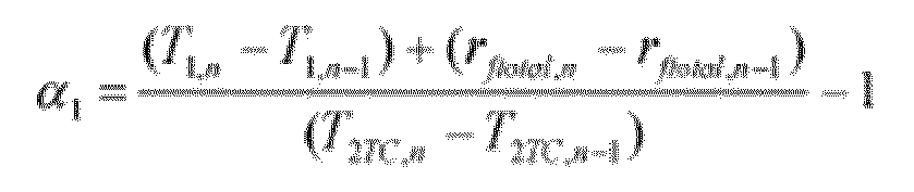
- T 1 ,n is the departure time of the nth timing message sent from the master device to the slave device
- T 2 TC,n is the arrival time of the nth timing message sent from the master device to the slave device at the transparent clock device
- r ftotal,n is the cumulative residence time of the nth timing message sent from the master device to the slave device in other transparent clock devices whilst travelling between the master device and the transparent clock device, calculating a component ⁇ 2 of the skew in
- the processor is arranged to estimate the skew of the local clock by operating a Kalman filter.
- Embodiments using a Kalman filter such as that above can also estimate the offset of the local clock compared to the master clock.
- the device of the present aspect may include any combination of some, all or none of the above described preferred and optional features.
- a third aspect of the present invention provides a networked time system according to claim 15.
- the skew of the local clock can be accurately estimated using the existing pattern of timing messages exchanged between the master and slave devices and without the need for physical synchronization or use of separate timing messages.
- timing messages are messages under the IEEE 1588 PTP.
- the processor is further arranged to syntonize the local clock to the master clock.
- syntonizing synchronizing the frequency
- the syntonization can be achieved by post-processing the output of a free-running local clock.
- the processor is further arranged to compute modified residence times in the transparent clock device using the estimated skew of the local clock.
- the accuracy of the synchronization of a clock in the slave device to the master clock can be improved as more accurate information regarding the delays in the network between the master and the salve device can be provided.
- all transparent clocks between the master and the slave would compute modified residence times in this manner, but improvements will result even if only one of the transparent clocks operates in this manner.
- the step of computing modified residence times uses a filtered value of the skew, for example using an exponentially weighted moving average filter.
- the master device and transparent clock device are capable of hardware timestamping arriving and outgoing timing messages
- the processor is arranged to extract the residence time by: extracting the residence time recorded in the timing messages sent from the master device to the slave device on arrival in the transparent clock device; and extracting the residence time recorded in the timing messages sent from the slave device to the master device on departure from the transparent clock device and the total residence time recorded between the slave device and the master device.
- the residence time in transparent clocks between the master device and the transparent clock device itself in the forward direction between the master and the slave can be determined from the residence time recorded in a timing message when it arrives at the transparent clock.
- the residence time in the same transparent clocks in the reverse direction (slave to master) is the difference between the residence time for all transparent clocks between the slave and the message leaving the transparent clock device itself and the total residence time for the entire journey from slave to master.
- the master device and transparent clock device are not capable of hardware timestamping the arriving and outgoing timing messages, wherein the master device is further arranged to: for each first timing message (e.g. an IEEE 1588 PTP "Sync” message (e.g. an IEEE 1588 PTP "Follow_Up” message) from the master device to the slave device which contains the time of sending of the respective first timing message by the master device, and to which is cumulatively added, by each transparent clock that the further timing message passes through, a first residence time being the time taken for the respective first timing message to pass through each said transparent clock device; and for each second timing message (e.g.
- first timing message e.g. an IEEE 1588 PTP "Sync” message (e.g. an IEEE 1588 PTP "Follow_Up” message) from the master device to the slave device which contains the time of sending of the respective first timing message by the master device, and to which is cumulatively added, by each transparent clock that the further timing message passes through, a first residence time being the time taken for the respective
- an IEEE 1588 PTP "Delay_Req” message sent from the slave device to the master device, send a second further timing message (e.g. an IEEE 1588 PTP "Delay_Resp” message) from the master device to the slave device which contains the time of receipt of the respective second timing message by the master device, and to which is cumulatively added, by each transparent clock that the second further timing message passes through, a second residence time being the time taken for the respective second timing message to pass through each said transparent clock device, and wherein the processor is further arranged to: extract the first residence time recorded in one of said first further timing messages; and extract the second residence time recorded in one of said second further timing messages on receipt of the second further timing message at the transparent clock device.
- a second further timing message e.g. an IEEE 1588 PTP "Delay_Resp” message
- the residence time in transparent clocks between the master device and the transparent clock device itself in the forward direction between the master and the slave can be determined from the residence time recorded in the first further timing message (e,g. "Follow_Up” message) when it arrives at the transparent clock.
- the residence time in the same transparent clocks in the reverse direction (slave to master) is recorded by the transparent clocks as the message (e.g. "Delay_Req” message) passes through those transparent clocks, but is added to the second further timing message (e.g. "Delay_Resp” message) when it is returned to the slave.
- the processor is arranged to estimate the skew of the local clock using a linear approximation.
- T 1 ,n is the departure time of the n th timing message sent from the master device to the slave device
- T 2 TC,n is the arrival time of the n th timing message sent from the master device to the slave device at the transparent clock device
- r ftotal,n is the cumulative residence time of the nth timing message sent from the master device to the slave device in other transparent clock devices whilst travelling between the master device and the transparent clock device, calculating a component ⁇ 2 of the
- the processor is further arranged to estimate the skew of the local clock by operating a Kalman filter.
- T 1 ,n is the departure time of the nth timing message sent from the master device to the slave device
- T 2 TC,n is the arrival time of the nth timing message sent from the master device to the slave device at the transparent clock device T 4
- n is the arrival time of the nth timing message sent from the slave device to the master
- Embodiments using a Kalman filter such as that above can also estimate the offset of the local clock compared to the master clock.
- the system of the present aspect may include any combination of some, all or none of the above described preferred and optional features.
- a free-running local oscillator is used at a TC.
- the frequency of this TC local oscillator is not adjusted physically, but it is allowed to free-run.
- This free-running oscillator drives a counter which is in turn used for timestamping at the TC and for the uncorrected measurement of the residence times of PTP messages.
- This time varying offset which reflects the true offset between the two clocks consists of two components, one being ⁇ in the (fixed) initial offset, and the other ⁇ C ( t ) which is an offset that arises as a result of the non-zero skew between the two clocks.
- Time synchronization in this sense will require knowing accurately the total offset ⁇ ( t ) or, equivalently, its constituent components ⁇ and ⁇ in , when given any C ( t ) value.
- TCs are capable of intercepting PTP messages and capturing embedded and external TC triggered timestamps. That is, a TC is capable of snooping on PTP messages passing through it. Assume there are K TCs 6 between the GM 1 and the slave 3. The following process takes place at the kth TC, 1 ⁇ k ⁇ K :
- the embedded and TC triggered timestamps captured at the TC 6 are used in the computation of the TC clock skew with respect to the GM 1. Techniques for estimating the skew according to embodiments of the present invention are described below.
- the basic clock model above can be extended to account for the case where the GM/master clock 4 and slave clock 5 exchange PTP messages and with messages intercepted and timestamps captured at a particular TC 6 as described above.
- the communication link between a GM 1 and a TC 6 has with it a fixed and random delay.
- the PTP messages pass through a network of one or multiple E2E TCs 6 from GM 1 to slave 3.
- nth Sync message travelling from the GM 1 to the kth TC 6 experiences a fixed physical link (or propagation) delay of d f plus variable cumulative residence time of r ftotal,n .
- nth Delay_Req message traveling from the kth TC 6 to the GM 1 experiences a fixed delay of d r plus variable cumulative residence time of r rtolal , n .
- the GM 1 and slave 3 exchange messages using the delay-request delay-response mechanism described above and illustrated in Figure 1 .
- ⁇ 2 denote the component of the skew that can be estimated from the Delay_Req message exchange.
- the estimated skew ⁇ is then used to compute the clock offset ⁇ in as given in (6). If further desired at any given discrete time n, the estimated skew ⁇ and offset ⁇ in can be used to estimate the server time S n corresponding to a local clock value C n .
- the residence times can be estimated given the computed skew ⁇ and the ingress and egress timestamps generated upon PTP message arrivals using the free-running TC clock as follows.
- C in and C eg denote, respectively, the ingress and egress timestamps captured by the kth TC upon a PTP message arrival at any time instance.
- ⁇ in also denote the initial time offset of the TC clock with respect to the GM clock.
- the ingress and egress timestamps are mapped to the ideal time reference, which in this case is that of the GM.
- filtered values of the skew ( ⁇ ) preferably should be used.
- EWMA exponentially weighted moving average
- the Kalman filter [1] allows the use of measurements of a process observed over time, containing noise and other inaccuracies, to produce values (estimates) that tend to be closer to the true values of the measurements and their associated calculated values.
- the Kalman filter produces estimates of the true values of measurements and their associated calculated values by predicting a value, estimating the uncertainty of the predicted value, and computing a weighted average of the predicted value and the measured value.
- the notation X ⁇ n , m used below represents the estimate of X at time n given observations up to, and including at time m.
- the Kalman filter equations are most often conceptualized as two distinct phases: Predict and Update as described below.
- the predict phase uses the state estimate from the previous time step to produce an estimate of the state at the current time step.
- This predicted state estimate is also known as the a priori state estimate because, although it is an estimate of the state at the current time step, it does not include observation information from the current time step.
- the current a priori prediction is combined with current observation information to refine the state estimate.
- This improved estimate is termed the a posteriori state estimate.
- the second term in the above equation is called the correction term and it represents the amount by which to correct the propagated state estimate due to the measurement. Inspection of the Kalman gain equation shows that if the measurement noise is large, R n will be large, so that K n will be small and not much credibility would be given to the measurement y when computing the next X ⁇ . On the other hand, if the measurement noise is small, R n will be small, so that K n will be large and a lot of credibility will be given to the measurement when computing the next X ⁇ .
- the two phases alternate, with the prediction advancing the state until the next scheduled observation, and the update incorporating the observation.
- Practical implementation of the Kalman Filter requires getting a good estimate of the noise covariance matrices Q n and R n .
- a Sync message travelling from a GM 1 to the kth TC 6 experiences a fixed delay d , variable cumulative residence time r ftotal , plus a stochastic delay ⁇ (to account for all other delay components in the system).
- y n ( T 1 ,n - T 2 TC,n ) + ( T 4, n - T 3 TC,n ) + ( d f - d r ) + ( r ftotal,n - r rtotal,n ) is a scalar.
- the quantity ( d f - d r ) accounts for the fixed delay asymmetry in
- the nth sampling interval is considered to be the period in which the nth Sync and nth Delay_Req messages exchanges occur.
- TC clock (process) model parameters A n and w n are derived.
- Q n E w n w n T .
- A is not a fixed matrix because of the variable message delays experienced in the system, thus making (42) the most appropriate expression to be used at each iteration.
- the clock skew ( ⁇ ) estimated at the TC using any of the two techniques described above can be used to compute the modified residence times as given by (19).
- a computer system includes the hardware, software and data storage devices for embodying a system or carrying out a method according to the above described embodiments.
- a computer system may comprise a central processing unit (CPU), input means, output means and data storage.
- the computer system has a monitor to provide a visual output display.
- the data storage may comprise RAM, disk drives or other computer readable media.
- the computer system may include a plurality of computing devices connected by a network and able to communicate with each other over that network.
- the methods of the above embodiments may be provided as computer programs or as computer program products or computer readable media carrying a computer program which is arranged, when run on a computer, to perform the method(s) described above.
- computer readable media includes, without limitation, any non-transitory medium or media which can be read and accessed directly by a computer or computer system.
- the media can include, but are not limited to, magnetic storage media such as floppy discs, hard disc storage media and magnetic tape; optical storage media such as optical discs or CD-ROMs; electrical storage media such as memory, including RAM, ROM and flash memory; and hybrids and combinations of the above such as magnetic/optical storage media.
Landscapes
- Engineering & Computer Science (AREA)
- Computer Networks & Wireless Communication (AREA)
- Signal Processing (AREA)
- Synchronisation In Digital Transmission Systems (AREA)
- Electric Clocks (AREA)
Claims (15)
- Procédé d'estimation de déphasage d'une horloge locale d'un dispositif d'horloge transparente (6) de bout en bout connecté par l'intermédiaire d'un réseau (2) avec un dispositif maître (1) ayant une horloge maître (4) et un dispositif esclave (3), le procédé comprenant les étapes consistant à :échanger des messages de synchronisation entre le dispositif maître (1) et le dispositif esclave (3) sur le réseau (2), les messages de synchronisation passant par ledit dispositif d'horloge transparente (6) ;enregistrer des heures d'envoi et de réception desdits messages de synchronisation par le dispositif maître (1) ;extraire, par le dispositif d'horloge transparente (6), à partir de messages de synchronisation envoyés du dispositif maître (1) au dispositif esclave (3), les heures d'envoi et de réception desdits messages de synchronisation ;enregistrer les temps de réception par le dispositif d'horloge transparente (6) de messages de synchronisation envoyés du dispositif maître (1) au dispositif esclave (3) ;enregistrer les temps d'envoi par le dispositif d'horloge transparente (6) de messages de synchronisation envoyés du dispositif esclave (3) au dispositif maître (3) ;extraire, par le dispositif d'horloge transparente (6), à partir des messages de synchronisation, le temps de séjour des messages de synchronisation dans d'autres dispositifs d'horloge transparente (6) entre le dispositif maître (1) et le dispositif d'horloge transparente (6) ;par le dispositif d'horloge transparente (6) : mesurer un temps de séjour de message pour un message de synchronisation passant par le dispositif d'horloge transparente, modifier un champ de correction dans le message de synchronisation reçu avec au moins le temps de séjour de message mesuré pour générer un champ de correction modifié dans le message de synchronisation envoyé du dispositif d'horloge transparente au dispositif esclave (3) ; etestimer, par le dispositif d'horloge transparente (6), le décalage de l'horloge locale du dispositif d'horloge transparente comparativement à l'horloge maître (4) à l'aide d'une pluralité de chacun desdits temps extraits et enregistrés.
- Procédé selon la revendication 1, comprenant en outre les étapes consistant à syntoniser l'horloge locale du dispositif d'horloge transparente (6) sur l'horloge maître (4) et syntoniser une deuxième horloge esclave (5) dans le dispositif esclave (3) sur l'horloge maîtresse.
- Procédé selon la revendication 1 ou la revendication 2, comprenant en outre l'étape consistant à calculer informatiquement des temps de séjour modifiés par le dispositif d'horloge transparente à l'aide du déphasage estimé de l'horloge locale.
- Procédé selon l'une quelconque des revendications précédentes, dans lequel le dispositif maître (1) et le dispositif d'horloge transparente (6) sont capables d'horodater matériellement des messages de synchronisation entrants et sortants, et l'étape consistant à extraire le temps de séjour comprend :l'extraction du temps de séjour enregistré dans les messages de synchronisation envoyés du dispositif maître (1) au dispositif esclave (3) à l'arrivée dans le dispositif d'horloge transparente (6) ; etl'extraction du temps de séjour enregistré dans les messages de synchronisation envoyés du dispositif esclave (3) au dispositif maître (1) au départ du dispositif d'horloge transparente (6) et le temps de séjour total enregistré entre le dispositif esclave et le dispositif maître.
- Procédé selon l'une quelconque des revendications 1 à 3, dans lequel le dispositif maître (1) et le dispositif d'horloge transparente (6) ne sont pas capables d'horodater matériellement les messages de synchronisation entrants et sortants, le procédé comprenant en outre les étapes consistant à :pour chaque premier message de synchronisation envoyé du dispositif maître (1) au dispositif esclave (3), envoyer un premier message de synchronisation supplémentaire du dispositif maître au dispositif esclave qui contient le temps d'envoi du premier message de synchronisation respectif par le dispositif maître, et auquel est ajouté cumulativement, par chaque horloge transparente (6) par laquelle passe le message de synchronisation supplémentaire, un premier temps de séjour qui est le temps pris par le premier message de synchronisation respectif pour passer par chacun desdits dispositifs d'horloge transparente ; etpour chaque deuxième message de synchronisation envoyé du dispositif esclave (3) au dispositif maître (1), envoyer un deuxième message de synchronisation supplémentaire du dispositif maître au dispositif esclave qui contient le temps de réception du deuxième message de synchronisation respectif par le dispositif maître, et auquel est ajouté cumulativement, par chaque horloge transparente (6) par laquelle passe le deuxième message de synchronisation supplémentaire, un deuxième temps de séjour qui est le temps pris par le deuxième message de synchronisation respectif pour passer par chacun desdits dispositifs d'horloge transparente,et dans lequel l'étape consistant à extraire le temps de séjour comprend :l'extraction du premier temps de séjour enregistré dans l'un desdits premiers messages de synchronisation supplémentaires ; etl'extraction du deuxième temps de séjour enregistré dans l'un desdits deuxièmes messages de synchronisation supplémentaires à la réception du deuxième message de synchronisation supplémentaire au niveau du dispositif d'horloge transparente (6).
- Procédé selon l'une quelconque des revendications précédentes dans lequel l'étape consistant à estimer le déphasage de l'horloge locale comprend :le calcul d'une composante α 1 du déphasage dans la direction avant du dispositif maître (1) au dispositif esclave (3), comme suit :
 le calcul d'une composante α 2 du déphasage dans la direction inverse du dispositif esclave au dispositif maître, comme suit :
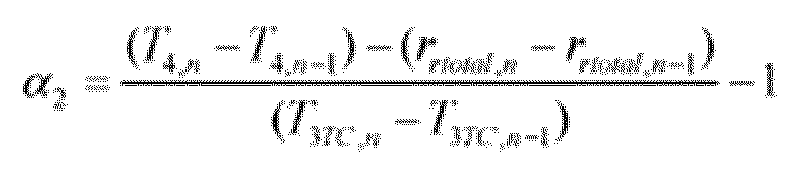 l'estimation du déphasage comme la moyenne de α 1 et α 2.
 - Procédé selon l'une quelconque des revendications 1 à 5 dans lequel l'étape consistant à estimer le déphasage de l'horloge locale comprend la mise en oeuvre d'un filtre de Kalman à l'aide de l'équation de mesure


et à l'aide de l'équation d'état :

- Dispositif d'horloge transparente (6) de bout en bout destiné à être utilisé dans un réseau (2) entre un dispositif maître (1) ayant une horloge maître (4) et un dispositif esclave (3), le dispositif d'horloge transparente ayant :une horloge locale ; etun processeur,dans lequel le dispositif d'horloge transparente est agencé pour :recevoir et retransmettre des messages de synchronisation envoyés dans les deux directions entre le dispositif maître (1) et le dispositif esclave (3) sur le réseau (2),et le processeur est agencé pour :extraire, à partir de messages de synchronisation envoyés du dispositif maître (1) au dispositif esclave (3), les temps d'envoi et de réception desdits messages de synchronisation ;enregistrer les temps de réception par le dispositif d'horloge transparente (6) de messages de synchronisation envoyés du dispositif maître (1) au dispositif esclave (3) ;enregistrer les temps de retransmission par le dispositif d'horloge transparente (6) de messages de synchronisation envoyés du dispositif esclave (3) au dispositif maître (1) ;extraire, à partir des messages de synchronisation, le temps de séjour des messages de synchronisation dans d'autres dispositifs d'horloge transparente (6) entre le dispositif maître (1) et le dispositif d'horloge transparente ;mesurer un temps de séjour de message pour un message de synchronisation passant par le dispositif d'horloge transparente (6), modifier un champ de correction dans le message de synchronisation reçu avec au moins le temps de séjour de message mesuré pour générer un champ de correction modifié dans le message de synchronisation envoyé du dispositif d'horloge transparente au dispositif esclave (3) ; etestimer le déphasage de l'horloge locale dans le dispositif d'horloge transparente (6) comparativement à l'horloge maître (4) à l'aide d'une pluralité de chacun desdits temps extraits et enregistrés.
- Dispositif d'horloge transparente (6) selon la revendication 8 dans lequel le processeur est en outre agencé pour syntoniser l'horloge locale dans le dispositif d'horloge transparente sur l'horloge maître (4).
- Dispositif d'horloge transparente (6) selon la revendication 8 ou la revendication 9 dans lequel le processeur est en outre agencé pour calculer informatiquement des temps de séjour modifiés dans le dispositif d'horloge transparente à l'aide du déphasage estimé de l'horloge locale.
- Dispositif d'horloge transparente (6) selon l'une quelconque des revendications 8 à 10, dans lequel le dispositif d'horloge transparente est capable d'horodater matériellement des messages de synchronisation entrants et sortants, et le processeur est agencé pour extraire le temps de séjour par :l'extraction du temps de séjour enregistré dans les messages de synchronisation envoyés du dispositif maître (1) au dispositif esclave (3) à l'arrivée dans le dispositif d'horloge transparente (6) ; etl'extraction du temps de séjour enregistré dans les messages de synchronisation envoyés du dispositif esclave (3) au dispositif maître (1) au départ du dispositif d'horloge transparente (6) et du temps de séjour total enregistré entre le dispositif esclave et le dispositif maître.
- Dispositif d'horloge transparente (6) selon l'une quelconque des revendications 8 à 11, dans lequel le dispositif d'horloge transparente n'est pas capable d'horodater matériellement les messages de synchronisation entrants et sortants, dans lequel :pour chaque premier message de synchronisation envoyé du dispositif maître (1) au dispositif esclave (3), envoyer un premier message de synchronisation supplémentaire du dispositif maître au dispositif esclave qui contient le temps d'envoi du premier message de synchronisation respectif par le dispositif maître, et auquel est ajouté cumulativement, par chaque horloge transparente (6) par laquelle passe le message de synchronisation supplémentaire, un premier temps de séjour qui est le temps pris par le premier message de synchronisation respectif pour passer par chacun desdits dispositifs d'horloge transparente ; etpour chaque deuxième message de synchronisation envoyé du dispositif esclave (3) au dispositif maître (1), envoyer un deuxième message de synchronisation supplémentaire du dispositif maître au dispositif esclave qui contient le temps de réception du deuxième message de synchronisation respectif par le dispositif maître, et auquel est ajouté cumulativement, par chaque horloge transparente (6) par laquelle passe le deuxième message de synchronisation supplémentaire, un deuxième temps de séjour qui est le temps pris par le deuxième message de synchronisation respectif pour passer par chacun desdits dispositifs d'horloge transparente,et dans lequel le processeur est agencé pour extraire le temps de séjour par :l'extraction du premier temps de séjour enregistré dans l'un desdits premiers messages de synchronisation supplémentaires ; etl'extraction du deuxième temps de séjour enregistré dans l'un desdits deuxièmes messages de synchronisation supplémentaires à la réception du deuxième message de synchronisation supplémentaire au niveau du dispositif d'horloge transparente (6).
- Dispositif d'horloge transparente (6) selon l'une quelconque des revendications 8 à 12 dans lequel le processeur est agencé pour estimer le déphasage de l'horloge locale par :le calcul d'une composante α 1 du déphasage dans la direction avant du dispositif maître au dispositif esclave, comme suit :
 le calcul d'une composante α 2 du déphasage dans la direction inverse du dispositif esclave (1) au dispositif maître (3), comme suit :
 l'estimation du déphasage comme la moyenne de α 1 et α 2.
 - Dispositif d'horloge transparente (6) selon l'une quelconque des revendications 8 à 12 dans lequel le processeur est agencé pour estimer le déphasage de l'horloge locale par la mise en oeuvre d'un filtre de Kalman à l'aide de l'équation de mesure


et à l'aide de l'équation d'état :

- Système de temps en réseau comprenant un dispositif maître (1) ayant une horloge maître (4) et un dispositif esclave (3), un réseau (2) connectant le dispositif maître au dispositif esclave et un dispositif d'horloge transparente (6) de bout en bout selon l'une quelconque des revendications 8 à 14 situé dans le réseau entre le dispositif maître et le dispositif esclave, dans lequel :le dispositif maître (1) et le dispositif esclave (3) sont agencés pour échanger des messages de synchronisation sur le réseau (2), les messages de synchronisation passant par ledit dispositif d'horloge transparente (6) ; etle dispositif maître (1) est agencé pour enregistrer des temps d'envoi et de réception desdits messages de synchronisation au niveau du dispositif maître.
Applications Claiming Priority (1)
| Application Number | Priority Date | Filing Date | Title |
|---|---|---|---|
| PCT/EP2018/069299 WO2020015814A1 (fr) | 2018-07-16 | 2018-07-16 | Horloges transparentes de bout en bout et procédés d'estimation de décalage dans des horloges transparentes de bout en bout |
Publications (2)
| Publication Number | Publication Date |
|---|---|
| EP3824574A1 EP3824574A1 (fr) | 2021-05-26 |
| EP3824574B1 true EP3824574B1 (fr) | 2024-07-24 |
Family
ID=62986088
Family Applications (1)
| Application Number | Title | Priority Date | Filing Date |
|---|---|---|---|
| EP18743746.2A Active EP3824574B1 (fr) | 2018-07-16 | 2018-07-16 | Horloges transparentes de bout en bout et procédés d'estimation de décalage dans des horloges transparentes de bout en bout |
Country Status (2)
| Country | Link |
|---|---|
| EP (1) | EP3824574B1 (fr) |
| WO (1) | WO2020015814A1 (fr) |
Family Cites Families (1)
| Publication number | Priority date | Publication date | Assignee | Title |
|---|---|---|---|---|
| WO2016092243A1 (fr) * | 2014-12-11 | 2016-06-16 | Khalifa University of Science, Technology, and Research | Procédé et dispositifs de transfert temporel a l'aide d'horloges transparentes de bout en bout |
-
2018
- 2018-07-16 EP EP18743746.2A patent/EP3824574B1/fr active Active
- 2018-07-16 WO PCT/EP2018/069299 patent/WO2020015814A1/fr not_active Ceased
Also Published As
| Publication number | Publication date |
|---|---|
| EP3824574A1 (fr) | 2021-05-26 |
| WO2020015814A1 (fr) | 2020-01-23 |
Similar Documents
| Publication | Publication Date | Title |
|---|---|---|
| US11018789B2 (en) | End-to-end transparent clocks and methods of estimating skew in end-to-end transparent clocks | |
| US10979164B2 (en) | Peer-to-peer transparent clocks and methods of estimating skew in peer-to-peer transparent clocks | |
| US9671822B2 (en) | Method and devices for time transfer using end-to-end transparent clocks | |
| US9665121B2 (en) | Method and devices for time transfer using peer-to-peer transparent clocks | |
| US9112628B2 (en) | Method and devices for compensating for path asymmetry | |
| EP2254267B1 (fr) | Récupération de synchronisation d'entrées multiples dans des réseaux par paquets | |
| EP3053289B1 (fr) | Procédé et dispositifs pour compenser une asymétrie de chemins | |
| CN102577194B (zh) | 使分布式网络内时钟同步的系统和方法 | |
| US9112631B2 (en) | Method and devices for frequency distribution | |
| US10505652B2 (en) | Methods and systems for estimating offset skew and drift | |
| EP3044891B1 (fr) | Procédé et dispositifs de distribution de fréquence | |
| US9270607B2 (en) | Method and devices for packet selection | |
| CN112166565A (zh) | 电缆网络的定时同步 | |
| JP2012222833A (ja) | 揺らぎの蓄積を克服して大きなネットワーク上で精密なクロック分配を達成するシステムおよび方法 | |
| Ronen et al. | Enhanced synchronization accuracy in IEEE1588 | |
| EP3231110B1 (fr) | Procédé et dispositifs de transfert temporel a l'aide d'horloges transparentes de bout en bout | |
| EP3231112B1 (fr) | Procédé et dispositifs de transfert temporel à l'aide d'horloges transparentes poste à poste | |
| EP3824573B1 (fr) | Horloges transparentes entre homologues et procédés d'estimation de biais dans des horloges transparentes entre homologues | |
| EP3824574B1 (fr) | Horloges transparentes de bout en bout et procédés d'estimation de décalage dans des horloges transparentes de bout en bout | |
| EP3732806B1 (fr) | Procédé, dispositif et système d'estimation de décalage, d'obliquité et de dérive | |
| EP3080951B1 (fr) | Procédé et dispositifs de sélection de paquets | |
| Qian et al. | Awakening power of physical layer: High precision time synchronization for industrial Ethernet |
Legal Events
| Date | Code | Title | Description |
|---|---|---|---|
| STAA | Information on the status of an ep patent application or granted ep patent |
Free format text: STATUS: UNKNOWN |
|
| STAA | Information on the status of an ep patent application or granted ep patent |
Free format text: STATUS: THE INTERNATIONAL PUBLICATION HAS BEEN MADE |
|
| PUAI | Public reference made under article 153(3) epc to a published international application that has entered the european phase |
Free format text: ORIGINAL CODE: 0009012 |
|
| STAA | Information on the status of an ep patent application or granted ep patent |
Free format text: STATUS: REQUEST FOR EXAMINATION WAS MADE |
|
| 17P | Request for examination filed |
Effective date: 20210105 |
|
| AK | Designated contracting states |
Kind code of ref document: A1 Designated state(s): AL AT BE BG CH CY CZ DE DK EE ES FI FR GB GR HR HU IE IS IT LI LT LU LV MC MK MT NL NO PL PT RO RS SE SI SK SM TR |
|
| DAV | Request for validation of the european patent (deleted) | ||
| DAX | Request for extension of the european patent (deleted) | ||
| GRAP | Despatch of communication of intention to grant a patent |
Free format text: ORIGINAL CODE: EPIDOSNIGR1 |
|
| STAA | Information on the status of an ep patent application or granted ep patent |
Free format text: STATUS: GRANT OF PATENT IS INTENDED |
|
| INTG | Intention to grant announced |
Effective date: 20240502 |
|
| GRAS | Grant fee paid |
Free format text: ORIGINAL CODE: EPIDOSNIGR3 |
|
| GRAA | (expected) grant |
Free format text: ORIGINAL CODE: 0009210 |
|
| STAA | Information on the status of an ep patent application or granted ep patent |
Free format text: STATUS: THE PATENT HAS BEEN GRANTED |
|
| AK | Designated contracting states |
Kind code of ref document: B1 Designated state(s): AL AT BE BG CH CY CZ DE DK EE ES FI FR GB GR HR HU IE IS IT LI LT LU LV MC MK MT NL NO PL PT RO RS SE SI SK SM TR |
|
| REG | Reference to a national code |
Ref country code: GB Ref legal event code: FG4D |
|
| REG | Reference to a national code |
Ref country code: CH Ref legal event code: EP |
|
| REG | Reference to a national code |
Ref country code: IE Ref legal event code: FG4D Ref country code: DE Ref legal event code: R096 Ref document number: 602018072178 Country of ref document: DE |
|
| REG | Reference to a national code |
Ref country code: LT Ref legal event code: MG9D |
|
| REG | Reference to a national code |
Ref country code: NL Ref legal event code: MP Effective date: 20240724 |
|
| PG25 | Lapsed in a contracting state [announced via postgrant information from national office to epo] |
Ref country code: PT Free format text: LAPSE BECAUSE OF FAILURE TO SUBMIT A TRANSLATION OF THE DESCRIPTION OR TO PAY THE FEE WITHIN THE PRESCRIBED TIME-LIMIT Effective date: 20241125 |
|
| REG | Reference to a national code |
Ref country code: AT Ref legal event code: MK05 Ref document number: 1707266 Country of ref document: AT Kind code of ref document: T Effective date: 20240724 |
|
| PG25 | Lapsed in a contracting state [announced via postgrant information from national office to epo] |
Ref country code: NL Free format text: LAPSE BECAUSE OF FAILURE TO SUBMIT A TRANSLATION OF THE DESCRIPTION OR TO PAY THE FEE WITHIN THE PRESCRIBED TIME-LIMIT Effective date: 20240724 |
|
| PG25 | Lapsed in a contracting state [announced via postgrant information from national office to epo] |
Ref country code: PT Free format text: LAPSE BECAUSE OF FAILURE TO SUBMIT A TRANSLATION OF THE DESCRIPTION OR TO PAY THE FEE WITHIN THE PRESCRIBED TIME-LIMIT Effective date: 20241125 Ref country code: NL Free format text: LAPSE BECAUSE OF FAILURE TO SUBMIT A TRANSLATION OF THE DESCRIPTION OR TO PAY THE FEE WITHIN THE PRESCRIBED TIME-LIMIT Effective date: 20240724 |
|
| PG25 | Lapsed in a contracting state [announced via postgrant information from national office to epo] |
Ref country code: NO Free format text: LAPSE BECAUSE OF FAILURE TO SUBMIT A TRANSLATION OF THE DESCRIPTION OR TO PAY THE FEE WITHIN THE PRESCRIBED TIME-LIMIT Effective date: 20241024 |
|
| PG25 | Lapsed in a contracting state [announced via postgrant information from national office to epo] |
Ref country code: FI Free format text: LAPSE BECAUSE OF FAILURE TO SUBMIT A TRANSLATION OF THE DESCRIPTION OR TO PAY THE FEE WITHIN THE PRESCRIBED TIME-LIMIT Effective date: 20240724 Ref country code: GR Free format text: LAPSE BECAUSE OF FAILURE TO SUBMIT A TRANSLATION OF THE DESCRIPTION OR TO PAY THE FEE WITHIN THE PRESCRIBED TIME-LIMIT Effective date: 20241025 Ref country code: PL Free format text: LAPSE BECAUSE OF FAILURE TO SUBMIT A TRANSLATION OF THE DESCRIPTION OR TO PAY THE FEE WITHIN THE PRESCRIBED TIME-LIMIT Effective date: 20240724 |
|
| PG25 | Lapsed in a contracting state [announced via postgrant information from national office to epo] |
Ref country code: BG Free format text: LAPSE BECAUSE OF FAILURE TO SUBMIT A TRANSLATION OF THE DESCRIPTION OR TO PAY THE FEE WITHIN THE PRESCRIBED TIME-LIMIT Effective date: 20240724 |
|
| PG25 | Lapsed in a contracting state [announced via postgrant information from national office to epo] |
Ref country code: LV Free format text: LAPSE BECAUSE OF FAILURE TO SUBMIT A TRANSLATION OF THE DESCRIPTION OR TO PAY THE FEE WITHIN THE PRESCRIBED TIME-LIMIT Effective date: 20240724 |
|
| PG25 | Lapsed in a contracting state [announced via postgrant information from national office to epo] |
Ref country code: IS Free format text: LAPSE BECAUSE OF FAILURE TO SUBMIT A TRANSLATION OF THE DESCRIPTION OR TO PAY THE FEE WITHIN THE PRESCRIBED TIME-LIMIT Effective date: 20241124 Ref country code: AT Free format text: LAPSE BECAUSE OF FAILURE TO SUBMIT A TRANSLATION OF THE DESCRIPTION OR TO PAY THE FEE WITHIN THE PRESCRIBED TIME-LIMIT Effective date: 20240724 |
|
| PG25 | Lapsed in a contracting state [announced via postgrant information from national office to epo] |
Ref country code: HR Free format text: LAPSE BECAUSE OF FAILURE TO SUBMIT A TRANSLATION OF THE DESCRIPTION OR TO PAY THE FEE WITHIN THE PRESCRIBED TIME-LIMIT Effective date: 20240724 |
|
| PG25 | Lapsed in a contracting state [announced via postgrant information from national office to epo] |
Ref country code: RS Free format text: LAPSE BECAUSE OF FAILURE TO SUBMIT A TRANSLATION OF THE DESCRIPTION OR TO PAY THE FEE WITHIN THE PRESCRIBED TIME-LIMIT Effective date: 20241024 Ref country code: ES Free format text: LAPSE BECAUSE OF FAILURE TO SUBMIT A TRANSLATION OF THE DESCRIPTION OR TO PAY THE FEE WITHIN THE PRESCRIBED TIME-LIMIT Effective date: 20240724 |
|
| PG25 | Lapsed in a contracting state [announced via postgrant information from national office to epo] |
Ref country code: RS Free format text: LAPSE BECAUSE OF FAILURE TO SUBMIT A TRANSLATION OF THE DESCRIPTION OR TO PAY THE FEE WITHIN THE PRESCRIBED TIME-LIMIT Effective date: 20241024 Ref country code: PL Free format text: LAPSE BECAUSE OF FAILURE TO SUBMIT A TRANSLATION OF THE DESCRIPTION OR TO PAY THE FEE WITHIN THE PRESCRIBED TIME-LIMIT Effective date: 20240724 Ref country code: NO Free format text: LAPSE BECAUSE OF FAILURE TO SUBMIT A TRANSLATION OF THE DESCRIPTION OR TO PAY THE FEE WITHIN THE PRESCRIBED TIME-LIMIT Effective date: 20241024 Ref country code: LV Free format text: LAPSE BECAUSE OF FAILURE TO SUBMIT A TRANSLATION OF THE DESCRIPTION OR TO PAY THE FEE WITHIN THE PRESCRIBED TIME-LIMIT Effective date: 20240724 Ref country code: IS Free format text: LAPSE BECAUSE OF FAILURE TO SUBMIT A TRANSLATION OF THE DESCRIPTION OR TO PAY THE FEE WITHIN THE PRESCRIBED TIME-LIMIT Effective date: 20241124 Ref country code: HR Free format text: LAPSE BECAUSE OF FAILURE TO SUBMIT A TRANSLATION OF THE DESCRIPTION OR TO PAY THE FEE WITHIN THE PRESCRIBED TIME-LIMIT Effective date: 20240724 Ref country code: GR Free format text: LAPSE BECAUSE OF FAILURE TO SUBMIT A TRANSLATION OF THE DESCRIPTION OR TO PAY THE FEE WITHIN THE PRESCRIBED TIME-LIMIT Effective date: 20241025 Ref country code: FI Free format text: LAPSE BECAUSE OF FAILURE TO SUBMIT A TRANSLATION OF THE DESCRIPTION OR TO PAY THE FEE WITHIN THE PRESCRIBED TIME-LIMIT Effective date: 20240724 Ref country code: ES Free format text: LAPSE BECAUSE OF FAILURE TO SUBMIT A TRANSLATION OF THE DESCRIPTION OR TO PAY THE FEE WITHIN THE PRESCRIBED TIME-LIMIT Effective date: 20240724 Ref country code: BG Free format text: LAPSE BECAUSE OF FAILURE TO SUBMIT A TRANSLATION OF THE DESCRIPTION OR TO PAY THE FEE WITHIN THE PRESCRIBED TIME-LIMIT Effective date: 20240724 Ref country code: AT Free format text: LAPSE BECAUSE OF FAILURE TO SUBMIT A TRANSLATION OF THE DESCRIPTION OR TO PAY THE FEE WITHIN THE PRESCRIBED TIME-LIMIT Effective date: 20240724 |
|
| PG25 | Lapsed in a contracting state [announced via postgrant information from national office to epo] |
Ref country code: DK Free format text: LAPSE BECAUSE OF FAILURE TO SUBMIT A TRANSLATION OF THE DESCRIPTION OR TO PAY THE FEE WITHIN THE PRESCRIBED TIME-LIMIT Effective date: 20240724 Ref country code: RO Free format text: LAPSE BECAUSE OF FAILURE TO SUBMIT A TRANSLATION OF THE DESCRIPTION OR TO PAY THE FEE WITHIN THE PRESCRIBED TIME-LIMIT Effective date: 20240724 Ref country code: SM Free format text: LAPSE BECAUSE OF FAILURE TO SUBMIT A TRANSLATION OF THE DESCRIPTION OR TO PAY THE FEE WITHIN THE PRESCRIBED TIME-LIMIT Effective date: 20240724 |
|
| PG25 | Lapsed in a contracting state [announced via postgrant information from national office to epo] |
Ref country code: EE Free format text: LAPSE BECAUSE OF FAILURE TO SUBMIT A TRANSLATION OF THE DESCRIPTION OR TO PAY THE FEE WITHIN THE PRESCRIBED TIME-LIMIT Effective date: 20240724 |
|
| PG25 | Lapsed in a contracting state [announced via postgrant information from national office to epo] |
Ref country code: CZ Free format text: LAPSE BECAUSE OF FAILURE TO SUBMIT A TRANSLATION OF THE DESCRIPTION OR TO PAY THE FEE WITHIN THE PRESCRIBED TIME-LIMIT Effective date: 20240724 |
|
| REG | Reference to a national code |
Ref country code: DE Ref legal event code: R097 Ref document number: 602018072178 Country of ref document: DE |
|
| PG25 | Lapsed in a contracting state [announced via postgrant information from national office to epo] |
Ref country code: IT Free format text: LAPSE BECAUSE OF FAILURE TO SUBMIT A TRANSLATION OF THE DESCRIPTION OR TO PAY THE FEE WITHIN THE PRESCRIBED TIME-LIMIT Effective date: 20240724 Ref country code: SK Free format text: LAPSE BECAUSE OF FAILURE TO SUBMIT A TRANSLATION OF THE DESCRIPTION OR TO PAY THE FEE WITHIN THE PRESCRIBED TIME-LIMIT Effective date: 20240724 |
|
| PLBE | No opposition filed within time limit |
Free format text: ORIGINAL CODE: 0009261 |
|
| STAA | Information on the status of an ep patent application or granted ep patent |
Free format text: STATUS: NO OPPOSITION FILED WITHIN TIME LIMIT |
|
| 26N | No opposition filed |
Effective date: 20250425 |
|
| PGFP | Annual fee paid to national office [announced via postgrant information from national office to epo] |
Ref country code: GB Payment date: 20250529 Year of fee payment: 8 |
|
| PGFP | Annual fee paid to national office [announced via postgrant information from national office to epo] |
Ref country code: FR Payment date: 20250610 Year of fee payment: 8 |
|
| PG25 | Lapsed in a contracting state [announced via postgrant information from national office to epo] |
Ref country code: SE Free format text: LAPSE BECAUSE OF FAILURE TO SUBMIT A TRANSLATION OF THE DESCRIPTION OR TO PAY THE FEE WITHIN THE PRESCRIBED TIME-LIMIT Effective date: 20240724 |
|
| PGFP | Annual fee paid to national office [announced via postgrant information from national office to epo] |
Ref country code: DE Payment date: 20250604 Year of fee payment: 8 |
|
| REG | Reference to a national code |
Ref country code: CH Ref legal event code: H13 Free format text: ST27 STATUS EVENT CODE: U-0-0-H10-H13 (AS PROVIDED BY THE NATIONAL OFFICE) Effective date: 20260224 |
|
| PG25 | Lapsed in a contracting state [announced via postgrant information from national office to epo] |
Ref country code: LU Free format text: LAPSE BECAUSE OF NON-PAYMENT OF DUE FEES Effective date: 20250716 |
|
| REG | Reference to a national code |
Ref country code: BE Ref legal event code: MM Effective date: 20250731 |
|
| PG25 | Lapsed in a contracting state [announced via postgrant information from national office to epo] |
Ref country code: BE Free format text: LAPSE BECAUSE OF NON-PAYMENT OF DUE FEES Effective date: 20250731 |
|
| PG25 | Lapsed in a contracting state [announced via postgrant information from national office to epo] |
Ref country code: CH Free format text: LAPSE BECAUSE OF NON-PAYMENT OF DUE FEES Effective date: 20250731 |