EP3824664B1 - Gestion de priorité à la qualité de relocalisation de flux de service - Google Patents
Gestion de priorité à la qualité de relocalisation de flux de service Download PDFInfo
- Publication number
- EP3824664B1 EP3824664B1 EP18934625.7A EP18934625A EP3824664B1 EP 3824664 B1 EP3824664 B1 EP 3824664B1 EP 18934625 A EP18934625 A EP 18934625A EP 3824664 B1 EP3824664 B1 EP 3824664B1
- Authority
- EP
- European Patent Office
- Prior art keywords
- radio bearer
- data radio
- data
- terminal device
- prioritization
- Prior art date
- Legal status (The legal status is an assumption and is not a legal conclusion. Google has not performed a legal analysis and makes no representation as to the accuracy of the status listed.)
- Active
Links
Images


Classifications
-
- H—ELECTRICITY
- H04—ELECTRIC COMMUNICATION TECHNIQUE
- H04W—WIRELESS COMMUNICATION NETWORKS
- H04W28/00—Network traffic management; Network resource management
- H04W28/02—Traffic management, e.g. flow control or congestion control
- H04W28/0252—Traffic management, e.g. flow control or congestion control per individual bearer or channel
-
- H—ELECTRICITY
- H04—ELECTRIC COMMUNICATION TECHNIQUE
- H04L—TRANSMISSION OF DIGITAL INFORMATION, e.g. TELEGRAPHIC COMMUNICATION
- H04L47/00—Traffic control in data switching networks
- H04L47/70—Admission control; Resource allocation
- H04L47/80—Actions related to the user profile or the type of traffic
- H04L47/805—QOS or priority aware
-
- H—ELECTRICITY
- H04—ELECTRIC COMMUNICATION TECHNIQUE
- H04W—WIRELESS COMMUNICATION NETWORKS
- H04W28/00—Network traffic management; Network resource management
- H04W28/02—Traffic management, e.g. flow control or congestion control
- H04W28/0252—Traffic management, e.g. flow control or congestion control per individual bearer or channel
- H04W28/0263—Traffic management, e.g. flow control or congestion control per individual bearer or channel involving mapping traffic to individual bearers or channels, e.g. traffic flow template [TFT]
-
- H—ELECTRICITY
- H04—ELECTRIC COMMUNICATION TECHNIQUE
- H04W—WIRELESS COMMUNICATION NETWORKS
- H04W28/00—Network traffic management; Network resource management
- H04W28/02—Traffic management, e.g. flow control or congestion control
- H04W28/0268—Traffic management, e.g. flow control or congestion control using specific QoS parameters for wireless networks, e.g. QoS class identifier [QCI] or guaranteed bit rate [GBR]
-
- H—ELECTRICITY
- H04—ELECTRIC COMMUNICATION TECHNIQUE
- H04W—WIRELESS COMMUNICATION NETWORKS
- H04W76/00—Connection management
- H04W76/20—Manipulation of established connections
Definitions
- Various example embodiments relate to wireless communications.
- the old data radio bearer may still contain packets from that QoS flow.
- QoS Quality of Service
- DRB data radio bearer
- said leftover packets on the old data radio bearer will be delayed.
- PBR prioritized bit rate
- UMTS universal mobile telecommunications system
- UTRAN radio access network
- LTE long term evolution
- WLAN wireless local area network
- WiFi worldwide interoperability for microwave access
- Bluetooth ® personal communications services
- PCS personal communications services
- WCDMA wideband code division multiple access
- UWB ultra-wideband
- IMS Internet Protocol multimedia subsystems
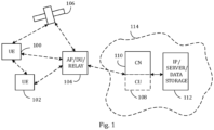
- Figure 1 depicts examples of simplified system architectures only showing some elements and functional entities, all being logical units, whose implementation may differ from what is shown.
- the connections shown in Figure 1 are logical connections; the actual physical connections may be different. It is apparent to a person skilled in the art that the system typically comprises also other functions and structures than those shown in Figure 1 .
- Figure 1 shows a part of an exemplifying radio access network.
- Figure 1 shows user devices 100 and 102 configured to be in a wireless connection on one or more communication channels in a cell with an access node (such as (e/g)NodeB) 104 providing the cell.
- the physical link from a user device to a (e/g)NodeB is called uplink or reverse link and the physical link from the (e/g)NodeB to the user device is called downlink or forward link.
- (e/g)NodeBs or their functionalities may be implemented by using any node, host, server or access point etc. entity suitable for such a usage.
- a communications system typically comprises more than one (e/g)NodeB in which case the (e/g)NodeBs may also be configured to communicate with one another over links, wired or wireless, designed for the purpose. These links may be used for signalling purposes.
- the (e/g)NodeB is a computing device configured to control the radio resources of communication system it is coupled to.
- the NodeB may also be referred to as a base station, an access point or any other type of interfacing device including a relay station capable of operating in a wireless environment.
- the (e/g)NodeB includes or is coupled to transceivers. From the transceivers of the (e/g)NodeB, a connection is provided to an antenna unit that establishes bi-directional radio links to user devices.
- the antenna unit may comprise a plurality of antennas or antenna elements.
- the (e/g)NodeB is further connected to core network 110 (CN or next generation core NGC).
- core network 110 CN or next generation core NGC.
- the counterpart on the CN side can be a serving gateway (S-GW, routing and forwarding user data packets), packet data network gateway (P-GW), for providing connectivity of user devices (UEs) to external packet data networks, or mobile management entity (MME), etc.
- S-GW serving gateway
- P-GW packet data network gateway
- MME mobile management entity
- the user device also called UE, user equipment, user terminal, terminal device, etc.
- UE user equipment
- user terminal terminal device
- any feature described herein with a user device may be implemented with a corresponding apparatus, such as a relay node.
- a relay node is a layer 3 relay (self-backhauling relay) towards the base station.
- the user device typically refers to a portable computing device that includes wireless mobile communication devices operating with or without a subscriber identification module (SIM), including, but not limited to, the following types of devices: a mobile station (mobile phone), smartphone, personal digital assistant (PDA), handset, device using a wireless modem (alarm or measurement device, etc.), laptop and/or touch screen computer, tablet, game console, notebook, and multimedia device.
- SIM subscriber identification module
- a user device may also be a nearly exclusive uplink only device, of which an example is a camera or video camera loading images or video clips to a network.
- a user device may also be a device having capability to operate in Internet of Things (IoT) network which is a scenario in which objects are provided with the ability to transfer data over a network without requiring human-to-human or human-to-computer interaction.
- IoT Internet of Things
- the user device (or in some embodiments a layer 3 relay node) is configured to perform one or more of user equipment functionalities.
- the user device may also be called a subscriber unit, mobile station, remote terminal, access terminal, user terminal or user equipment (UE) just to mention but a few names or apparatuses.
- CPS cyber-physical system
- ICT devices sensors, actuators, processors microcontrollers, etc.
- Mobile cyber physical systems in which the physical system in question has inherent mobility, are a subcategory of cyber-physical systems. Examples of mobile physical systems include mobile robotics and electronics transported by humans or animals.
- apparatuses have been depicted as single entities, different units, processors and/or memory units (not all shown in Figure 1 ) may be implemented.
- 5G enables using multiple input - multiple output (MIMO) antennas, many more base stations or nodes than the LTE (a so-called small cell concept), including macro sites operating in co-operation with smaller stations and employing a variety of radio technologies depending on service needs, use cases and/or spectrum available.
- MIMO multiple input - multiple output
- 5G mobile communications supports a wide range of use cases and related applications including video streaming, augmented reality, different ways of data sharing and various forms of machine type applications, including vehicular safety, different sensors and real-time control.
- 5G is expected to have multiple radio interfaces, namely below 6GHz, cmWave and mmWave, and also being integradable with existing legacy radio access technologies, such as the LTE.
- Integration with the LTE may be implemented, at least in the early phase, as a system, where macro coverage is provided by the LTE and 5G radio interface access comes from small cells by aggregation to the LTE.
- 5G is planned to support both inter-RAT operability (such as LTE-5G) and inter-RI operability (inter-radio interface operability, such as below 6GHz - cmWave, below 6GHz - cmWave - mmWave).
- inter-RAT operability such as LTE-5G
- inter-RI operability inter-radio interface operability, such as below 6GHz - cmWave, below 6GHz - cmWave - mmWave.
- One of the concepts considered to be used in 5G networks is network slicing in which multiple independent and dedicated virtual sub-networks (network instances) may be created within the same infrastructure to run services that have different requirements on latency, reliability, throughput and mobility.
- the current architecture in LTE networks is fully distributed in the radio and fully centralized in the core network.
- the low latency applications and services in 5G require to bring the content close to the radio which leads to local break out and multi-access edge computing (MEC).
- MEC multi-access edge computing
- 5G enables analytics and knowledge generation to occur at the source of the data. This approach requires leveraging resources that may not be continuously connected to a network such as laptops, smartphones, tablets and sensors.
- MEC provides a distributed computing environment for application and service hosting. It also has the ability to store and process content in close proximity to cellular subscribers for faster response time.
- Edge computing covers a wide range of technologies such as wireless sensor networks, mobile data acquisition, mobile signature analysis, cooperative distributed peer-to-peer ad hoc networking and processing also classifiable as local cloud/fog computing and grid/mesh computing, dew computing, mobile edge computing, cloudlet, distributed data storage and retrieval, autonomic self-healing networks, remote cloud services, augmented and virtual reality, data caching, Internet of Things (massive connectivity and/or latency critical), critical communications (autonomous vehicles, traffic safety, real-time analytics, time-critical control, healthcare applications).
- the communication system is also able to communicate with other networks, such as a public switched telephone network or the Internet 112, or utilize services provided by them.
- the communication network may also be able to support the usage of cloud services, for example at least part of core network operations may be carried out as a cloud service (this is depicted in Figure 1 by "cloud" 114).
- the communication system may also comprise a central control entity, or a like, providing facilities for networks of different operators to cooperate for example in spectrum sharing.
- Edge cloud may be brought into radio access network (RAN) by utilizing network function virtualization (NVF) and software defined networking (SDN).
- RAN radio access network
- NVF network function virtualization
- SDN software defined networking
- Using edge cloud may mean access node operations to be carried out, at least partly, in a server, host or node operationally coupled to a remote radio head or base station comprising radio parts. It is also possible that node operations will be distributed among a plurality of servers, nodes or hosts.
- Application of cloudRAN architecture enables RAN real time functions being carried out at the RAN side (in a distributed unit, DU 104) and non-real time functions being carried out in a centralized manner (in a centralized unit, CU 108).
- 5G may also utilize satellite communication to enhance or complement the coverage of 5G service, for example by providing backhauling.
- Possible use cases are providing service continuity for machine-to-machine (M2M) or Internet of Things (IoT) devices or for passengers on board of vehicles, or ensuring service availability for critical communications, and future railway/maritime/aeronautical communications.
- Satellite communication may utilise geostationary earth orbit (GEO) satellite systems, but also low earth orbit (LEO) satellite systems, in particular mega-constellations (systems in which hundreds of (nano)satellites are deployed).
- GEO geostationary earth orbit
- LEO low earth orbit
- mega-constellations systems in which hundreds of (nano)satellites are deployed.
- Each satellite 106 in the mega-constellation may cover several satellite-enabled network entities that create on-ground cells.
- the on-ground cells may be created through an on-ground relay node 104 or by a gNB located on-ground or in a satellite.
- the depicted system is only an example of a part of a radio access system and in practice, the system may comprise a plurality of (e/g)NodeBs, the user device may have an access to a plurality of radio cells and the system may comprise also other apparatuses, such as physical layer relay nodes or other network elements, etc. At least one of the (e/g)NodeBs or may be a Home(e/g)nodeB. Additionally, in a geographical area of a radio communication system a plurality of different kinds of radio cells as well as a plurality of radio cells may be provided.
- Radio cells may be macro cells (or umbrella cells) which are large cells, usually having a diameter of up to tens of kilometers, or smaller cells such as micro-, femto- or picocells.
- the (e/g)NodeBs of Figure 1 may provide any kind of these cells.
- a cellular radio system may be implemented as a multilayer network including several kinds of cells. Typically, in multilayer networks, one access node provides one kind of a cell or cells, and thus a plurality of (e/g)NodeBs are required to provide such a network structure.
- a network which is able to use “plug-and-play" (e/g)Node Bs includes, in addition to Home (e/g)NodeBs (H(e/g)nodeBs), a home node B gateway, or HNB-GW (not shown in Figure 1 ).
- HNB-GW HNB Gateway
- a HNB Gateway (HNB-GW) which is typically installed within an operator's network may aggregate traffic from a large number of HNBs back to a core network.
- the embodiments relate to the 5G Quality of Service (QoS) model or framework.
- the radio access network (RAN) in 5G controls data radio bearers (DRB) independently from the core network (CN).
- DRB data radio bearers
- the RAN decides on DRB configuration and how QoS flows are mapped to DRBs.
- (5G) QoS flow may be defined as the finest granularity for QoS forwarding treatment in the 5G System (CN+RAN). All traffic mapped to the same 5G QoS Flow receive the same forwarding treatment (e.g., scheduling policy, queue management policy, rate shaping policy, RLC configuration, etc.). Providing different QoS forwarding treatment, therefore, requires separate 5G QoS Flows.
- the 5G QoS framework was designed with the goal of reducing of control plane signaling in mind. To achieve this, the 5G QoS framework specifies a reflective QoS (RQoS) for service data flow to QoS flow mapping, i.e., a non-access stratum (NAS) layer mapping (i.e., within CN). More importantly for the following embodiments, the 5G QoS framework specifies a reflective QoS also for QoS flow to DRB mapping, i.e., an access stratum (AS) layer mapping (i.e., within RAN). The idea of reflective QoS is that each terminal device derives uplink mapping filters and mapping rules by itself from the downlink traffic so that network signaling over the control plane is not needed.
- RQoS reflective QoS
- NAS non-access stratum
- AS access stratum
- a QoS flow identifier (QFI) needs to be included into the downlink (data) packets, e.g., in a Service Data Adaptation Protocol (SDAP) header, where SDAP is a RAN protocol responsible for QoS Flow handling across the 5G air interface (Uu interface).
- SDAP Service Data Adaptation Protocol
- the terminal device is able to determine the QoS flow and consequently also which mapping rule to use (i.e., which data radio bearer to use for a specific QoS flow). Further, each terminal device may need to be indicated on which layer (NAS or AS) the reflective QoS is to be performed with the data packet.
- Each QoS flow identifier is associated with a certain QoS profile (i.e., QoS parameters and QoS characteristics).
- the QoS flow identifier may be defined as a scalar that is used as a reference to a specific QoS forwarding behavior (e.g. packet loss rate, packet delay budget) to be provided to a QoS Flow. This may be implemented in the access network by the 5QI referencing node specific parameters that control the QoS forwarding treatment (e.g., scheduling weights, admission thresholds, queue management thresholds, link layer protocol configuration, etc.).
- the data radio bearer defines the data packet treatment on the radio interface.
- a given data radio bearer serves data packets with the same data packet forwarding treatment.
- Separate data radio bearers may be established for QoS flows requiring different data packet forwarding treatment, or several QoS Flows belonging to the same protocol data unit (PDU) session can be multiplexed in the same data radio bearer.
- PDU protocol data unit
- the terminal device monitors the QFI(s) of the downlink data packets (included, e.g., in a SDAP header) for each data radio bearer and applies the same QoS flow to data radio bearer mapping in the uplink.
- the terminal device maps, for each data radio bearer, the uplink data packets belonging to the QoS flows(s) corresponding to the QFI(s) and PDU Session observed in the downlink data packets for that DRB.
- the NextGen(NG)-RAN i.e., the access node
- marks using SDAP downlink data packets over Uu with QFI.
- explicit configuration of the QoS flow to DRB mapping rules may also be possible using Radio Resource Control (RRC) signaling.
- RRC Radio Resource Control
- the terminal device may always apply the latest update of the mapping rules regardless of whether it was performed via reflecting mapping or explicit configuration.
- the terminal device may send an end marker on the old data radio bearer.
- a default data radio bearer For each PDU session, a default data radio bearer may be configured. If an incoming uplink data packet matches neither an RRC configured nor a reflective mapping rule, the terminal device may then map that data packet to the default data radio bearer of the PDU session. Within each PDU session, NG-RAN may map multiple QoS flows to a DRB.
- a logical channel providing by definition services for the medium access control (MAC) layer may be configured for each data radio bearer.
- a priority of a data radio bearer may specifically be the priority of the corresponding logical channel in MAC.
- the prioritized bit rate (PBR) and the logical channel prioritization (LCP) parameters to be discussed in relation to embodiments may be the prioritized bit rate and the LCP parameters of the corresponding logical channel, respectively.
- a transmission queue of the old data radio bearer may still contain data packets from the QoS flow associated with said new QoS flow to data radio bearer mapping rule.
- said leftover packets on the old data radio bearer will be delayed.
- the larger the queue on the old data radio bearer and the smaller the prioritized bit rate of the old data radio bearer the more serious the problem.
- the problem is further exacerbated in New Radio due to pre-processing, which allows the terminal device to build a large number of PDUs before uplink transmission.
- the embodiments provide a solution for overcoming or at least alleviating said problem.
- Figure 2 illustrates a process according to an embodiment for facilitating smooth QoS flow relocation (i.e., for updating a QoS flow to data radio bearer mapping without causing undue delays).
- the illustrated process may be performed by a terminal device of a wireless communications system or specifically any of the terminal devices 100, 102 of Figure 1 . While the process is discussed in the following in terms of an access node carrying out the process, in other embodiments another network (possibly in communication with an access node) may carry out the illustrated process fully or partly.
- the terminal device relocates, in block 201, a quality of service, QoS, flow from a first data radio bearer to a second data radio bearer.
- QoS quality of service
- the second data radio bearer may have a higher priority than the first data radio bearer.
- the terminal device temporarily adjusts, in block 202, one or more prioritization parameters associated with the first data radio bearer to (temporarily) prioritize the first data radio bearer.
- the first data radio bearer may be temporarily prioritized over one or more other data radio bearers which may or may not comprise the second data radio bearer.
- the first data radio bearer may be temporarily prioritized equally compared to the second data radio bearer.
- the adjustment in block 202 may be temporary in the sense that the adjustment is reversed (or cancelled) once the transmission queue of the first data radio bearer is empty of any data packets associated with the relocated QoS flow (as will be discussed in more detail in relation to Figure 3 ).
- the first data radio bearer may be a default data radio bearer of a corresponding protocol data unit (PDU) session and the second data radio bearer may be a data radio bearer associated with a tailored QoS (or QoS flow identifier or Qos profile).
- PDU protocol data unit
- the second data radio bearer may be a data radio bearer associated with a tailored QoS (or QoS flow identifier or Qos profile).
- the terminal device may perform the temporary adjusting only if out-of-sequence delivery is not configured by a layer higher than the data link layer.
- the one or more prioritization parameters may comprise one or more sets of prioritization parameters of different types, each set comprising at least one prioritization parameter.
- the one or more prioritization parameters may comprise at least a priority of the first data radio bearer, i.e., the priority of the logical channel used for that data radio bearer.
- the priority may be defined, for example, to have an integer value with a pre-defined range (e.g., 1 to 256) with an increasing priority value indicating a lower or higher priority depending on the definition.
- the temporary adjusting of the one or more prioritization parameters in block 202 may comprise at least temporarily assigning the first data radio bearer a priority assigned for the second data radio bearer (which may be assumed to correspond to higher priority than the first data radio bearer).
- the first data radio bearer may be assigned a first pre-defined value which may or may not be defined to be dependent on the priority of the second data radio bearer (e.g., a priority of 1 or a priority of two times the priority of the second data radio bearer).
- the first pre-defined value may be lower or higher than the priority of the second data radio bearer.
- the one or more prioritization parameters may comprise at least a prioritized bit rate of the first data radio bearer.
- a prioritized bit rate may be configured per data radio bearer, i.e., per logical channel.
- the prioritized bit rate may be defined as the bit rate provided to one logical channel before allocating any resource to a lower-priority logical channel.
- the prioritized bit rate is used to ensure that high priority logical channels are scheduled first while avoiding the starvation of lower priority ones. In other words, the prioritized bit rate is used to guarantee that certain QoS is achieved for each data radio bearer in uplink.
- the temporary adjusting of the one or more prioritization parameters in block 202 may comprise at least temporarily setting the prioritized bit rate of the first data radio bearer to a second pre-defined value.
- the second pre-defined value may correspond to infinity or to a finite (high) value. If the prioritized bit rate of a logical channel is set to infinity, the terminal device (i.e., the MAC entity of the terminal device) may allocate resources for all the data that is available for transmission on the logical channel before meeting the prioritized bit rate of the lower priority logical channel(s).
- the one or more prioritization parameters may comprise at least a pre-defined set of logical channel prioritization (LCP) parameters.
- the temporary adjusting of the one or more prioritization parameters in block 202 may comprise at least temporarily using the pre-defined set of logical channel prioritization parameters for the first radio bearer.
- the pre-defined set of logical channel prioritization parameters may have been configured earlier by the radio access network (or the access node) to the terminal device and may be maintained in a database of the terminal device.
- the LCP parameters may be parameters of a LCP procedure which are applied whenever a new transmission is performed.
- the access node may control the scheduling of uplink data by signaling (RRC signaling) for each logical channel per MAC entity (of a terminal device) one or more sets of LCP parameters.
- the (pre-defined set of) LCP parameters may comprise one or more of a priority (defined so that an increasing priority value indicates a lower priority level), a prioritized bit rate (as discussed above) and a bucket size duration (BSD).
- the bucket size duration may indicate the amount of time (e.g., in milliseconds) that it takes for a bucket size to be reached when transmitting uplink data of a logical channel using the prioritized bit rate.
- the bucket size may be defined as BSD ⁇ PBR indicating maximum uplink data which may be buffered.
- the bucket size duration is basically used to set the maximum amount of pending data allowed for a logical channel, with respect to the prioritization checks.
- the (pre-defined set of) LCP parameters may further define one or more mapping restrictions for each logical channel comprising a list of allowed subcarrier spacing(s) for transmission, a maximum PUSCH duration allowed for transmission, a parameter (or a list) defining whether a Configured Grant Type 1 can be used for transmission and/or a list of allowed cell(s) for transmission.
- the LCP procedure associated with the LCP parameters may be carried out as follows. Initially, the terminal device (i.e., the MAC entity of the terminal device) may initialize B j of the logical channel j (a variable of the terminal device) to zero when the logical channel is established. For each logical channel j , the terminal device (i.e., the MAC entity) may increment B j by the product PBR ⁇ T before every instance of the LCP procedure, where T is the time elapsed since B j was last updated. If the value of B j is greater than the bucket size (i.e., PBR ⁇ BSD), the terminal device (i.e., the MAC entity) may set B j to the bucket size.
- the terminal device i.e., the MAC entity
- Figure 3 illustrates another process according to an embodiment for facilitating smooth QoS flow relocation.
- the illustrated process may be performed by any terminal device of a wireless communications system or specifically any of the terminal devices 100, 102 of Figure 1 .
- the terminal device initially receives, in block 301, a request for updating a QoS flow to data radio bearer mapping rule from an access node.
- the request may be for updating the QoS flow to data radio bearer mapping rule so as to relocate a QoS flow from a first data radio bearer (a first mapping) to a second data radio bearer (a second mapping).
- the proceeding block 302 may correspond to block 201 of Figure 2 and is thus not repeated here for brevity.
- the terminal device adjusts, in block 303, one or more prioritization parameters associated with the first data bearer to prioritize the first data radio bearer.
- the one or more prioritization parameters and the adjusting of the one or more prioritization parameters may be defined as discussed in relation to Figure 1 with the distinction that the adjusting in block 303 (by itself) is not temporary.
- the temporary nature of the adjusting (as mentioned in relation to block 202 of Figure 2 ) is implemented in this embodiment specifically according to blocks 304 to 308 as will be discussed in the following.
- block 202 of Figure 2 may correspond to (or comprise) blocks 303 to 308 of Figure 3 or at least some of them.
- the terminal device may check (or determine or monitor) a status of the transmission queue of the first data bearer (i.e., at least how many data packets associated with said QoS flow are buffered). Specifically, if the transmission queue of the first data radio bearer comprises one or more data packets associated with said QoS flow in blocks 304, the terminal device causes transmitting, in block 305, on the first data radio bearer one or more data packets on the transmission queue of the first data radio bearer according to the one or more prioritization parameters (to an access node or one or more access nodes).
- a status of the transmission queue of the first data bearer i.e., at least how many data packets associated with said QoS flow are buffered. Specifically, if the transmission queue of the first data radio bearer comprises one or more data packets associated with said QoS flow in blocks 304, the terminal device causes transmitting, in block 305, on the first data radio bearer one or more data packets on the transmission queue of the first data radio bearer according
- the terminal device may cause transmitting, in block 305, n data packets, where n is equal to the number of said one or more data packets. Then, the terminal device detects, in block 306, that there are no data packets associated with the QoS flow on the transmission queue of the first data bearer. In other words, the terminal device detects that the first data bearer is no longer needed for transmitting data packets associated with the QoS flow. In response to the detecting in block 306, the terminal device causes transmitting, in block 307, an end marker on the first data radio bearer to an access node according to the one or more prioritization parameters. The transmitting of the end marker in block 307 may comprise, for example, introducing (or generating or constructing) and causing transmitting a separate control PDU (an end marker control PDU).
- a separate control PDU an end marker control PDU
- the terminal device After transmitting the end marker, the terminal device readjusts, in block 308, said one or more prioritization parameters to match values of said one or more prioritization parameters before the adjusting in block 303 (or before/at the time of the relocating in block 302). In other words, the terminal device reverts said one or more prioritization parameters for the first data radio bearer back to their original values.
- the terminal device operates according to the one or more prioritization parameters of the first data radio bearer, not only data packets of the QoS flow (that is, the relocated QoS flow) in the transmission queue of the first data radio bearer but also any data packets of other QoS flows in the transmission queue of the first data radio bearer may be prioritized.
- the terminal device directly detects, in block 306, that no data packets associated with the QoS flow exist on the transmission queue, causes transmitting, in block 307, the end marker to the access node according to the one or more prioritization parameters and readjusts, in block 308, the one or more prioritization parameters as described above.
- FIG 4 illustrates an alternative process according to embodiments using a signaling diagram between an access node and a terminal device for updating a QoS flow to data radio bearer mapping rule.
- the illustrated process may be performed by any of the terminal devices 100, 102 of Figure 1 and the access node 104 of Figure 1 .
- RLC AM Radio Link Control Acknowledged Mode
- the RLC AM is conventionally used when a reliable channel is required as, in RLC AM, a positive acknowledgment is transmitted upon a reception of each transmitted PDU.
- the access node transmits, in message 401, a request for updating a QoS flow to data radio bearer mapping rule which is subsequently received, in block 402, by the terminal device.
- the terminal device updates, in block 403, the corresponding mapping rule according to the received request (i.e., relocates the QoS flow from a first data radio bearer to a second data radio bearer potentially having a higher priority).
- the terminal device adjusts, in block 404, the one or more prioritization parameters (e.g., priority, PBR and/or LCP parameters) to prioritize the first data bearer.
- the terminal device may, thereafter, check the status of the transmission queue of the first data radio bearer (not shown in Figure 4 ). In this illustrated example, it is assumed that the transmission queue of the first data radio bearer comprises two or more data packets associated with the QoS flow.
- the terminal receives, in messages 405, downlink transmission from the access node and causes transmitting, also in messages 405, in uplink (according to the adjusted one or more prioritization parameters in the case of the first radio data bearer).
- the terminal device monitors downlink data packets for QoS flow identifiers, selects a data radio bearer for uplink based on the QoS flow defined in the QoS flow identifier and QoS flow to data radio bearer mapping rules and causes transmitting uplink data packets on the selected data radio bearer (i.e., on the first radio data bearer, on the second radio data bearer and/or on other radio data bearers).
- the second data radio bearer is selected based on the updated mapping rule for uplink transmission if the QoS flow identifier identifies the relocated QoS flow.
- the terminal device also causes transmitting, in messages 405, any buffered data packets (which may or may not be associated with the relocated QoS flow) in a transmission queue of the first data bearer.
- the terminal device detects, in block 406, that no packets associated with the (relocated) QoS flow exist in a transmission queue of the first data bearer and consequently generates, in block 407, a control PDU corresponding to an end marker (i.e., an end marker control PDU) and causes transmitting, in message 408, the end marker control PDU to the access node.
- the access node receives, in block 409, the end marker control PDU and consequently causes transmitting, in message 410, an acknowledgment acknowledging the successful reception of the end marker. Only in response to receiving the acknowledgment in block 411, the terminal device readjusts, in block 412, said one or more prioritization parameters to match values of said one or more prioritization parameters before the adjusting in block 404.
- the acknowledgment in message 410 may not be enough to trigger the readjusting in block 411. Instead, the terminal device may perform the readjusting only if also an acknowledgment for receiving a PDU (or a service data unit, SDU) directly preceding the end marker (end marker control PDU) is received. In yet another embodiment, the terminal device may perform the readjusting only if acknowledgments for the end marker and for one or more PDUs or SDUs directly preceding the end marker (end marker control PDU) are received.
- the Radio Link Control Unacknowledged Mode may be used, instead of the RLC AM.
- the readjusting of the one or more prioritization parameters may be performed in response to the transmitting of the end marker on the first radio data bearer (i.e., in response to the end marker being included in an uplink PDU to be sent to an access node).
- the techniques and methods described herein may be implemented by various means so that an apparatus/device configured to temporarily prioritize transmission on the first (old) data radio bearer based on at least partly on what is disclosed above with any of Figures 2 , 3 and 4 , including implementing one or more functions/operations of a corresponding terminal device or access node (or network element) described above with an embodiment/example, for example by means of any of Figures 2 , 3 and 4 . Further, the implementation may comprise separate means for each separate function/operation, or means may be configured to perform two or more functions/operations.
- one or more of the means described above may be implemented in hardware (one or more devices), firmware (one or more devices), software (one or more modules), or combinations thereof.
- the apparatus(es) of embodiments may be implemented within one or more application-specific integrated circuits (ASICs), digital signal processors (DSPs), digital signal processing devices (DSPDs), programmable logic devices (PLDs), field programmable gate arrays (FPGAs), processors, controllers, microcontrollers, microprocessors, logic gates, decoder circuitries, encoder circuitries, other electronic units designed to perform the functions described herein by means of Figures 2 , 3 and 4 , or a combination thereof.
- ASICs application-specific integrated circuits
- DSPs digital signal processors
- DSPDs digital signal processing devices
- PLDs programmable logic devices
- FPGAs field programmable gate arrays
- processors controllers, microcontrollers, microprocessors, logic gates, decoder circuitries, encoder circuitries, other electronic units designed to
- the implementation can be carried out through modules of at least one chipset (e.g., procedures, functions, and so on) that perform the functions described herein.
- the software codes may be stored in a memory unit and executed by processors.
- the memory unit may be implemented within the processor or externally to the processor. In the latter case, it can be communicatively coupled to the processor via various means, as is known in the art.
- the components described herein may be rearranged and/or complemented by additional components in order to facilitate the achievements of the various aspects, etc., described with regard thereto, and they are not limited to the precise configurations set forth in the given figures, as will be appreciated by one skilled in the art.
- Figure 5 provides a terminal device or other network node or network element (apparatus, device) according to some embodiments.
- Figure 5 may illustrate a terminal device configured to carry out at least the functions described above in connection with prioritizing an old (first) data radio bearer in response to a relocation of a QoS flow.
- Each terminal device may comprise one or more communication control circuitry 520, such as at least one processor, and at least one memory 530, including one or more algorithms 531, such as a computer program code (software) wherein the at least one memory and the computer program code (software) are configured, with the at least one processor, to cause, respectively, the terminal device to carry out any one of the exemplified functionalities of the terminal device described above.
- the communication control circuitry 521 of the access node 501 comprises at least mapping rule update circuitry 521.
- the mapping rule update circuitry 521 may be configured to relocate a QoS flow from one data radio bearer to another (i.e., to update a QoS flow to data radio bearer mapping rule) and to temporarily adjust (i.e., increase) prioritization for the old data radio bearer and, to this end, to carry out at least some of the functionalities described above by means of any of Figures 2 , 3 and 4 using one or more individual circuitries.
- the memory 530 may be implemented using any suitable data storage technology, such as semiconductor based memory devices, flash memory, magnetic memory devices and systems, optical memory devices and systems, fixed memory and removable memory.
- the access node or the terminal device may further comprise different interfaces 510 such as one or more communication interfaces (TX/RX) comprising hardware and/or software for realizing communication connectivity over the medium according to one or more communication protocols.
- the communication interface 510 for a terminal device may provide the terminal device with communication capabilities to communicate in the cellular communication system and enable communication between user devices (terminal devices) and to different network nodes or elements (e.g., to one or more access nodes).
- the communication interface may comprise standard well-known components such as an amplifier, filter, frequency-converter, (de)modulator, and encoder/decoder circuitries, controlled by the corresponding controlling units, and one or more antennas.
- the terminal device may also comprise different user interfaces.
- circuitry' may refer to one or more or all of the following: (a) hardware-only circuit implementations, such as implementations in only analog and/or digital circuitry, and (b) combinations of hardware circuits and software (and/or firmware), such as (as applicable): (i) a combination of analog and/or digital hardware circuit(s) with software/firmware and (ii) any portions of hardware processor(s) with software, including digital signal processor(s), software, and memory(ies) that work together to cause an apparatus, such as a terminal device or an access node, to perform various functions, and (c) hardware circuit(s) and processor(s), such as a microprocessor(s) or a portion of a microprocessor(s), that requires software (e.g.
- circuitry' also covers an implementation of merely a hardware circuit or processor (or multiple processors) or a portion of a hardware circuit or processor and its (or their) accompanying software and/or firmware.
- the term 'circuitry' also covers, for example and if applicable to the particular claim element, a baseband integrated circuit for an access node or a terminal device or other computing or network device.
- the at least one processor, the memory, and the computer program code form processing means or comprises one or more computer program code portions for carrying out one or more operations according to any one of the embodiments of Figures 2 , 3 and 4 or operations thereof.
- Embodiments as described may also be carried out in the form of a computer process defined by a computer program or portions thereof. Embodiments of the methods described in connection with Figures 2 , 3 and 4 may be carried out by executing at least one portion of a computer program comprising corresponding instructions.
- the computer program may be provided as a computer readable medium comprising program instructions stored thereon or as a non-transitory computer readable medium comprising program instructions stored thereon.
- the computer program may be in source code form, object code form, or in some intermediate form, and it may be stored in some sort of carrier, which may be any entity or device capable of carrying the program.
- the computer program may be stored on a computer program distribution medium readable by a computer or a processor.
- the computer program medium may be, for example but not limited to, a record medium, computer memory, read-only memory, electrical carrier signal, telecommunications signal, and software distribution package, for example.
- the computer program medium may be a non-transitory medium. Coding of software for carrying out the embodiments as shown and described is well within the scope of a person of ordinary skill in the art.
Landscapes
- Engineering & Computer Science (AREA)
- Computer Networks & Wireless Communication (AREA)
- Signal Processing (AREA)
- Mobile Radio Communication Systems (AREA)
Claims (15)
- Dispositif terminal (100, 102) comprenant :
des moyens pour, en réponse à la relocalisation (201) d'un flux de qualité de service, QoS, d'un premier support radio de données à un deuxième support radio de données, ajuster temporairement (202) un ou plusieurs paramètres de hiérarchisation associés au premier support radio de données pour prioriser le premier support radio de données, dans lequel les un ou plusieurs paramètres de hiérarchisation comprennent au moins un parmi une priorité du premier support radio de données, un débit binaire prioritaire du premier support radio de données ou un ensemble prédéfini de paramètres de hiérarchisation de canal logique, LCP, pour réaliser une procédure LCP. - Dispositif terminal (100, 102) selon la revendication 1, dans lequel l'ajustement (202) des un ou plusieurs paramètres de hiérarchisation comprend :l'ajustement (303, 404) des un ou plusieurs paramètres de hiérarchisation associés au premier support radio de données pour prioriser le premier support radio de données ;en réponse à une file d'attente de transmission du premier support radio de données comprenant un ou plusieurs paquets de données associés au flux QoS (304), la provocation (305, 405) de la transmission sur le premier support radio de données des un ou plusieurs paquets de données dans la file d'attente de transmission selon les un ou plusieurs paramètres de hiérarchisation ; eten réponse à la non détection (304, 306, 406) de paquets de données associés au flux QoS dans la file d'attente de transmission du premier support radio de données, la provocation (307, 408) de la transmission d'un marqueur de fin sur le premier support radio de données à un noeud d'accès selon les un ou plusieurs paramètres de hiérarchisation, et le réajustement (308, 411) des un ou plusieurs paramètres de hiérarchisation pour faire concorder les valeurs des un ou plusieurs paramètres de hiérarchisation avant l'ajustement (202, 303, 404) des un ou plusieurs paramètres de hiérarchisation.
- Dispositif terminal (100, 102) selon la revendication 2, dans lequel la provocation (307, 408) de la transmission du marqueur de fin comprend la génération d'une unité de données de protocole, PDU, de commande correspondant au marqueur de fin, et la provocation de la transmission de la PDU de commande.
- Dispositif terminal (100, 102) selon l'une des revendications 2 et 3, dans lequel un mode de commande de liaison radio avec accusé de réception, RLC AM, est utilisé dans le dispositif terminal (100, 102), et le réajustement (308, 411) des un ou plusieurs paramètres de hiérarchisation est réalisé en réponse à la réception, du noeud d'accès, d'un accusé de réception du marqueur de fin, d'un accusé de réception d'une unité de données de protocole, PDU, ou d'une unité de données de service, SDU, précédant directement le marqueur de fin, ou d'accusés de réception du marqueur de fin et d'une ou plusieurs PDU ou SDU précédant directement le marqueur de fin.
- Dispositif terminal (100, 102) selon l'une des revendications 2 et 3, dans lequel un mode de commande de liaison radio sans accusé de réception, RLC UM, est utilisé dans le dispositif terminal (100, 102), et le réajustement (308, 411) des un ou plusieurs paramètres de hiérarchisation est réalisé en réponse à la provocation (307, 408) de la transmission du marqueur de fin sur le premier support radio de données.
- Dispositif terminal (100, 102) selon l'une des revendications précédentes, dans lequel les un ou plusieurs paramètres de hiérarchisation comprennent au moins la priorité du premier support radio de données, et l'ajustement des un ou plusieurs paramètres de hiérarchisation comprend au moins l'attribution au premier support radio de données de la priorité attribuée pour le deuxième support radio de données ou d'une première valeur prédéfinie.
- Dispositif terminal (100, 102) selon l'une des revendications précédentes, dans lequel les un ou plusieurs paramètres de hiérarchisation comprennent au moins le débit binaire prioritaire du premier support radio de données, et l'ajustement des un ou plusieurs paramètres de hiérarchisation comprend au moins le réglage du débit binaire prioritaire du premier support radio de données à une deuxième valeur prédéfinie.
- Dispositif terminal (100, 102) selon la revendication 7, dans lequel la deuxième valeur prédéfinie correspond à l'infini.
- Dispositif terminal (100, 102) selon l'une des revendications précédentes, dans lequel les un ou plusieurs paramètres de hiérarchisation comprennent au moins l'ensemble prédéfini de paramètres LCP, et l'ajustement des un ou plusieurs paramètres de hiérarchisation comprend au moins l'utilisation de l'ensemble prédéfini de paramètres de hiérarchisation de canal logique pour le premier support radio de données.
- Dispositif terminal (100, 102) selon l'une des revendications précédentes, dans lequel la relocalisation (201) du flux QoS est réalisée en réponse à la réception, d'un noeud d'accès (104), d'une demande de mise à jour d'une règle de mappage d'un mappage du flux QoS au premier support radio de données à un mappage du flux QoS au deuxième support radio de données.
- Dispositif terminal (101, 102) selon l'une des revendications précédentes, dans lequel l'ajustement (202) des un ou plusieurs paramètres de hiérarchisation n'est réalisé que si la distribution hors séquence n'est pas configurée par une couche supérieure à une couche de liaison de données.
- Dispositif terminal (100, 102) selon l'une des revendications précédentes, dans lequel le premier support radio de données est un support radio de données par défaut d'une session d'unité de données de protocole, PDU, correspondante, et le deuxième support radio de données est un support radio de données associé à une QoS adaptée.
- Dispositif terminal selon l'une des revendications précédentes, dans lequel l'ajustement des un ou plusieurs paramètres de hiérarchisation n'est réalisé que si le deuxième support radio de données a une priorité plus élevée que le premier support radio de données avant l'ajustement.
- Procédé comprenant :
en réponse à la relocalisation (201) d'un flux de qualité de service, QoS, d'un premier support radio de données à un deuxième support radio de données, ajuster temporairement (202) un ou plusieurs paramètres de hiérarchisation associés au premier support de données pour prioriser le premier support radio de données, dans lequel les un ou plusieurs paramètres de hiérarchisation comprennent au moins un parmi une priorité du premier support radio de données, un débit binaire prioritaire du premier support radio de données ou un ensemble prédéfini de paramètres de hiérarchisation de canal logique, LCP, pour réaliser une procédure LCP. - Support lisible par ordinateur comprenant des instructions de programme qui, lorsqu'elles sont exécutées par un ordinateur, amènent un appareil à réaliser au moins ce qui suit :
en réponse à la relocalisation (201) d'un flux de qualité de service, QoS, d'un premier support radio de données à un deuxième support radio de données, ajuster temporairement (202) un ou plusieurs paramètres de hiérarchisation associés au premier support de données pour prioriser le premier support radio de données, dans lequel les un ou plusieurs paramètres de hiérarchisation comprennent au moins un parmi une priorité du premier support radio de données, un débit binaire prioritaire du premier support radio de données ou un ensemble prédéfini de paramètres de hiérarchisation de canal logique, LCP, pour réaliser une procédure LCP.
Applications Claiming Priority (1)
| Application Number | Priority Date | Filing Date | Title |
|---|---|---|---|
| PCT/CN2018/107587 WO2020061806A1 (fr) | 2018-09-26 | 2018-09-26 | Gestion de priorité à la qualité de relocalisation de flux de service |
Publications (3)
| Publication Number | Publication Date |
|---|---|
| EP3824664A1 EP3824664A1 (fr) | 2021-05-26 |
| EP3824664A4 EP3824664A4 (fr) | 2022-03-23 |
| EP3824664B1 true EP3824664B1 (fr) | 2024-10-23 |
Family
ID=69950202
Family Applications (1)
| Application Number | Title | Priority Date | Filing Date |
|---|---|---|---|
| EP18934625.7A Active EP3824664B1 (fr) | 2018-09-26 | 2018-09-26 | Gestion de priorité à la qualité de relocalisation de flux de service |
Country Status (4)
| Country | Link |
|---|---|
| US (1) | US20220053362A1 (fr) |
| EP (1) | EP3824664B1 (fr) |
| CN (1) | CN112640524A (fr) |
| WO (1) | WO2020061806A1 (fr) |
Families Citing this family (8)
| Publication number | Priority date | Publication date | Assignee | Title |
|---|---|---|---|---|
| EP3788816B1 (fr) * | 2018-05-15 | 2025-10-15 | Sony Group Corporation | Appareil et procédés de communications sans fil |
| GB2600098B (en) * | 2020-10-15 | 2024-03-27 | Samsung Electronics Co Ltd | QoS management framework |
| US20240147192A1 (en) * | 2021-03-11 | 2024-05-02 | Interdigital Ce Intermediate, Sas | Methods, apparatuses and systems directed to dynamic use of multicast radio resources |
| US11711716B2 (en) * | 2021-04-16 | 2023-07-25 | Qualcomm Incorporated | Techniques for improving reflective quality of service |
| CN113766481B (zh) * | 2021-10-14 | 2023-11-28 | 山东鑫泽网络科技有限公司 | 一种网络通信装置及方法 |
| CN116761210B (zh) * | 2023-08-11 | 2023-12-15 | 深圳国人无线通信有限公司 | 5qi业务流到drb的映射方法和系统 |
| WO2025067767A1 (fr) * | 2023-09-28 | 2025-04-03 | Nokia Technologies Oy | Transmission de données sur une porteuse radio |
| WO2026036744A1 (fr) * | 2024-08-14 | 2026-02-19 | Huawei Technologies Co., Ltd. | Nouvelle couche pour la gestion de qs dans le traitement et le transfert de données |
Family Cites Families (19)
| Publication number | Priority date | Publication date | Assignee | Title |
|---|---|---|---|---|
| US6901060B1 (en) * | 2000-05-17 | 2005-05-31 | Nokia Corporation | Method and apparatus for multiplexing a plurality of data connections onto one temporary block flow |
| CN101572911B (zh) * | 2002-09-24 | 2012-12-19 | 富士通株式会社 | 数据包传输/发送方法及移动通信系统 |
| CN1968198A (zh) * | 2006-06-16 | 2007-05-23 | 华为技术有限公司 | 一种无线接入承载分组数据业务的QoS管理方法 |
| US8670394B2 (en) * | 2007-08-14 | 2014-03-11 | Qualcomm Incorporated | Uplink requests |
| US8064382B2 (en) * | 2007-09-28 | 2011-11-22 | Wireless Technology Solutions Llc | Apparatus and method for scheduling in a wireless communication system |
| EP2587859A1 (fr) * | 2011-10-31 | 2013-05-01 | Alcatel Lucent | Appareil, procédé et programme informatique pour signaler une information de congestion de ressources radio |
| US9743447B2 (en) * | 2012-01-18 | 2017-08-22 | Lg Electronics Inc. | Control method and device based on multiple priorities in wireless communication system |
| CN104854773B (zh) * | 2013-01-14 | 2018-05-11 | 英特尔Ip公司 | 无线网络中的能量采集设备 |
| US10028212B2 (en) * | 2013-11-22 | 2018-07-17 | Qualcomm Incorporated | Techniques for provisioning configuration information based on cell characteristics |
| JP2017017553A (ja) * | 2015-07-01 | 2017-01-19 | 富士通株式会社 | 移動通信システム及びゲートウェイ装置 |
| US10827501B2 (en) * | 2016-02-25 | 2020-11-03 | Nokia Solutions And Networks Oy | Techniques for providing proximity services (ProSe) priority-related information to a base station in a wireless network |
| US10485005B2 (en) * | 2016-07-26 | 2019-11-19 | Industrial Technology Research Institute | Method and apparatuses for controlling quality of experience based on UE-assisted feedback |
| CN107733678B (zh) * | 2016-08-12 | 2022-12-13 | 华为技术有限公司 | 无线通信系统的服务质量管理方法和系统 |
| CN107889154A (zh) * | 2016-09-30 | 2018-04-06 | 华为技术有限公司 | 一种通信方法及装置 |
| CN109005127B (zh) * | 2017-02-03 | 2020-03-10 | 华为技术有限公司 | 一种QoS流处理方法、设备和通信系统 |
| US11006311B2 (en) * | 2017-05-16 | 2021-05-11 | Qualcomm Incorporated | Ethernet over cellular |
| KR102591104B1 (ko) * | 2017-06-16 | 2023-10-19 | 삼성전자 주식회사 | 서빙 셀을 전환하는 방법 및 디바이스와 온디맨드 시스템 정보 메시지를 지원하는 방법 및 디바이스 |
| CN115767629A (zh) * | 2018-01-10 | 2023-03-07 | 三星电子株式会社 | 用于无线通信系统中的无线通信的方法和装置 |
| US11064417B2 (en) * | 2018-05-10 | 2021-07-13 | Telefonaktiebolaget Lm Ericsson (Publ) | QoS and hop-aware adaptation layer for multi-hop integrated access backhaul system |
-
2018
- 2018-09-26 EP EP18934625.7A patent/EP3824664B1/fr active Active
- 2018-09-26 WO PCT/CN2018/107587 patent/WO2020061806A1/fr not_active Ceased
- 2018-09-26 US US17/274,847 patent/US20220053362A1/en not_active Abandoned
- 2018-09-26 CN CN201880096945.4A patent/CN112640524A/zh active Pending
Also Published As
| Publication number | Publication date |
|---|---|
| EP3824664A1 (fr) | 2021-05-26 |
| US20220053362A1 (en) | 2022-02-17 |
| CN112640524A (zh) | 2021-04-09 |
| EP3824664A4 (fr) | 2022-03-23 |
| WO2020061806A1 (fr) | 2020-04-02 |
Similar Documents
| Publication | Publication Date | Title |
|---|---|---|
| EP3735006B1 (fr) | Calcul efficace de données d'application dans un réseau de communication mobile | |
| US11368993B2 (en) | Communicating vehicular communication messages | |
| US10716031B2 (en) | Network node configured to provide wireless access with enhanced resource allocation | |
| US20220053362A1 (en) | Priority handling at quality of service flow relocation | |
| US11711718B2 (en) | Communication efficiency | |
| US11252546B2 (en) | Receiving vehicular communication messages | |
| US20230379920A1 (en) | Mutliplexing and transmitting cancelled uplink control information | |
| US20240187914A1 (en) | Methods and apparatuses for controlling small data transmission on uplink | |
| EP3857951B1 (fr) | Restriction de cellule de canal logique | |
| WO2020120825A1 (fr) | Communications par paquets | |
| US20240206011A1 (en) | Radio bearer reconfiguration | |
| WO2020037675A1 (fr) | Indication de priorité de données pour autorisation de liaison montante | |
| WO2024187455A1 (fr) | Commande de découpage basée sur un débit binaire priorisé | |
| US12587898B2 (en) | Data arrival indication | |
| WO2024167527A1 (fr) | Coordination de ressources basée sur la fronthaul | |
| US20220407621A1 (en) | Controlling duplicate transmissions in multi-connectivity mode | |
| US11863288B2 (en) | Relaying transmissions | |
| EP4346146A1 (fr) | Détermination de forme d'onde pour une transmission en liaison montante |
Legal Events
| Date | Code | Title | Description |
|---|---|---|---|
| STAA | Information on the status of an ep patent application or granted ep patent |
Free format text: STATUS: THE INTERNATIONAL PUBLICATION HAS BEEN MADE |
|
| PUAI | Public reference made under article 153(3) epc to a published international application that has entered the european phase |
Free format text: ORIGINAL CODE: 0009012 |
|
| STAA | Information on the status of an ep patent application or granted ep patent |
Free format text: STATUS: REQUEST FOR EXAMINATION WAS MADE |
|
| 17P | Request for examination filed |
Effective date: 20210219 |
|
| AK | Designated contracting states |
Kind code of ref document: A1 Designated state(s): AL AT BE BG CH CY CZ DE DK EE ES FI FR GB GR HR HU IE IS IT LI LT LU LV MC MK MT NL NO PL PT RO RS SE SI SK SM TR |
|
| DAV | Request for validation of the european patent (deleted) | ||
| DAX | Request for extension of the european patent (deleted) | ||
| REG | Reference to a national code |
Ref country code: DE Ref legal event code: R079 Free format text: PREVIOUS MAIN CLASS: H04W0028100000 Ipc: H04W0076200000 Ref document number: 602018075872 Country of ref document: DE |
|
| A4 | Supplementary search report drawn up and despatched |
Effective date: 20220217 |
|
| RIC1 | Information provided on ipc code assigned before grant |
Ipc: H04L 47/80 20220101ALI20220211BHEP Ipc: H04W 28/02 20090101ALI20220211BHEP Ipc: H04W 28/10 20090101ALI20220211BHEP Ipc: H04W 76/20 20180101AFI20220211BHEP |
|
| GRAP | Despatch of communication of intention to grant a patent |
Free format text: ORIGINAL CODE: EPIDOSNIGR1 |
|
| STAA | Information on the status of an ep patent application or granted ep patent |
Free format text: STATUS: GRANT OF PATENT IS INTENDED |
|
| INTG | Intention to grant announced |
Effective date: 20240516 |
|
| GRAS | Grant fee paid |
Free format text: ORIGINAL CODE: EPIDOSNIGR3 |
|
| GRAA | (expected) grant |
Free format text: ORIGINAL CODE: 0009210 |
|
| STAA | Information on the status of an ep patent application or granted ep patent |
Free format text: STATUS: THE PATENT HAS BEEN GRANTED |
|
| AK | Designated contracting states |
Kind code of ref document: B1 Designated state(s): AL AT BE BG CH CY CZ DE DK EE ES FI FR GB GR HR HU IE IS IT LI LT LU LV MC MK MT NL NO PL PT RO RS SE SI SK SM TR |
|
| REG | Reference to a national code |
Ref country code: GB Ref legal event code: FG4D |
|
| REG | Reference to a national code |
Ref country code: CH Ref legal event code: EP |
|
| REG | Reference to a national code |
Ref country code: DE Ref legal event code: R096 Ref document number: 602018075872 Country of ref document: DE |
|
| REG | Reference to a national code |
Ref country code: IE Ref legal event code: FG4D |
|
| REG | Reference to a national code |
Ref country code: LT Ref legal event code: MG9D |
|
| REG | Reference to a national code |
Ref country code: NL Ref legal event code: MP Effective date: 20241023 |
|
| REG | Reference to a national code |
Ref country code: AT Ref legal event code: MK05 Ref document number: 1735911 Country of ref document: AT Kind code of ref document: T Effective date: 20241023 |
|
| PG25 | Lapsed in a contracting state [announced via postgrant information from national office to epo] |
Ref country code: NL Free format text: LAPSE BECAUSE OF FAILURE TO SUBMIT A TRANSLATION OF THE DESCRIPTION OR TO PAY THE FEE WITHIN THE PRESCRIBED TIME-LIMIT Effective date: 20241023 |
|
| PG25 | Lapsed in a contracting state [announced via postgrant information from national office to epo] |
Ref country code: NL Free format text: LAPSE BECAUSE OF FAILURE TO SUBMIT A TRANSLATION OF THE DESCRIPTION OR TO PAY THE FEE WITHIN THE PRESCRIBED TIME-LIMIT Effective date: 20241023 |
|
| PG25 | Lapsed in a contracting state [announced via postgrant information from national office to epo] |
Ref country code: IS Free format text: LAPSE BECAUSE OF FAILURE TO SUBMIT A TRANSLATION OF THE DESCRIPTION OR TO PAY THE FEE WITHIN THE PRESCRIBED TIME-LIMIT Effective date: 20250223 Ref country code: PT Free format text: LAPSE BECAUSE OF FAILURE TO SUBMIT A TRANSLATION OF THE DESCRIPTION OR TO PAY THE FEE WITHIN THE PRESCRIBED TIME-LIMIT Effective date: 20250224 Ref country code: HR Free format text: LAPSE BECAUSE OF FAILURE TO SUBMIT A TRANSLATION OF THE DESCRIPTION OR TO PAY THE FEE WITHIN THE PRESCRIBED TIME-LIMIT Effective date: 20241023 |
|
| PG25 | Lapsed in a contracting state [announced via postgrant information from national office to epo] |
Ref country code: FI Free format text: LAPSE BECAUSE OF FAILURE TO SUBMIT A TRANSLATION OF THE DESCRIPTION OR TO PAY THE FEE WITHIN THE PRESCRIBED TIME-LIMIT Effective date: 20241023 |
|
| PG25 | Lapsed in a contracting state [announced via postgrant information from national office to epo] |
Ref country code: BG Free format text: LAPSE BECAUSE OF FAILURE TO SUBMIT A TRANSLATION OF THE DESCRIPTION OR TO PAY THE FEE WITHIN THE PRESCRIBED TIME-LIMIT Effective date: 20241023 |
|
| PG25 | Lapsed in a contracting state [announced via postgrant information from national office to epo] |
Ref country code: ES Free format text: LAPSE BECAUSE OF FAILURE TO SUBMIT A TRANSLATION OF THE DESCRIPTION OR TO PAY THE FEE WITHIN THE PRESCRIBED TIME-LIMIT Effective date: 20241023 |
|
| PG25 | Lapsed in a contracting state [announced via postgrant information from national office to epo] |
Ref country code: NO Free format text: LAPSE BECAUSE OF FAILURE TO SUBMIT A TRANSLATION OF THE DESCRIPTION OR TO PAY THE FEE WITHIN THE PRESCRIBED TIME-LIMIT Effective date: 20250123 |
|
| PG25 | Lapsed in a contracting state [announced via postgrant information from national office to epo] |
Ref country code: AT Free format text: LAPSE BECAUSE OF FAILURE TO SUBMIT A TRANSLATION OF THE DESCRIPTION OR TO PAY THE FEE WITHIN THE PRESCRIBED TIME-LIMIT Effective date: 20241023 Ref country code: GR Free format text: LAPSE BECAUSE OF FAILURE TO SUBMIT A TRANSLATION OF THE DESCRIPTION OR TO PAY THE FEE WITHIN THE PRESCRIBED TIME-LIMIT Effective date: 20250124 Ref country code: LV Free format text: LAPSE BECAUSE OF FAILURE TO SUBMIT A TRANSLATION OF THE DESCRIPTION OR TO PAY THE FEE WITHIN THE PRESCRIBED TIME-LIMIT Effective date: 20241023 |
|
| PG25 | Lapsed in a contracting state [announced via postgrant information from national office to epo] |
Ref country code: PL Free format text: LAPSE BECAUSE OF FAILURE TO SUBMIT A TRANSLATION OF THE DESCRIPTION OR TO PAY THE FEE WITHIN THE PRESCRIBED TIME-LIMIT Effective date: 20241023 |
|
| PG25 | Lapsed in a contracting state [announced via postgrant information from national office to epo] |
Ref country code: RS Free format text: LAPSE BECAUSE OF FAILURE TO SUBMIT A TRANSLATION OF THE DESCRIPTION OR TO PAY THE FEE WITHIN THE PRESCRIBED TIME-LIMIT Effective date: 20250123 |
|
| PG25 | Lapsed in a contracting state [announced via postgrant information from national office to epo] |
Ref country code: SM Free format text: LAPSE BECAUSE OF FAILURE TO SUBMIT A TRANSLATION OF THE DESCRIPTION OR TO PAY THE FEE WITHIN THE PRESCRIBED TIME-LIMIT Effective date: 20241023 |
|
| PG25 | Lapsed in a contracting state [announced via postgrant information from national office to epo] |
Ref country code: DK Free format text: LAPSE BECAUSE OF FAILURE TO SUBMIT A TRANSLATION OF THE DESCRIPTION OR TO PAY THE FEE WITHIN THE PRESCRIBED TIME-LIMIT Effective date: 20241023 |
|
| PG25 | Lapsed in a contracting state [announced via postgrant information from national office to epo] |
Ref country code: EE Free format text: LAPSE BECAUSE OF FAILURE TO SUBMIT A TRANSLATION OF THE DESCRIPTION OR TO PAY THE FEE WITHIN THE PRESCRIBED TIME-LIMIT Effective date: 20241023 |
|
| PG25 | Lapsed in a contracting state [announced via postgrant information from national office to epo] |
Ref country code: RO Free format text: LAPSE BECAUSE OF FAILURE TO SUBMIT A TRANSLATION OF THE DESCRIPTION OR TO PAY THE FEE WITHIN THE PRESCRIBED TIME-LIMIT Effective date: 20241023 |
|
| REG | Reference to a national code |
Ref country code: DE Ref legal event code: R097 Ref document number: 602018075872 Country of ref document: DE |
|
| PG25 | Lapsed in a contracting state [announced via postgrant information from national office to epo] |
Ref country code: SK Free format text: LAPSE BECAUSE OF FAILURE TO SUBMIT A TRANSLATION OF THE DESCRIPTION OR TO PAY THE FEE WITHIN THE PRESCRIBED TIME-LIMIT Effective date: 20241023 |
|
| PG25 | Lapsed in a contracting state [announced via postgrant information from national office to epo] |
Ref country code: CZ Free format text: LAPSE BECAUSE OF FAILURE TO SUBMIT A TRANSLATION OF THE DESCRIPTION OR TO PAY THE FEE WITHIN THE PRESCRIBED TIME-LIMIT Effective date: 20241023 |
|
| PG25 | Lapsed in a contracting state [announced via postgrant information from national office to epo] |
Ref country code: IT Free format text: LAPSE BECAUSE OF FAILURE TO SUBMIT A TRANSLATION OF THE DESCRIPTION OR TO PAY THE FEE WITHIN THE PRESCRIBED TIME-LIMIT Effective date: 20241023 |
|
| PLBE | No opposition filed within time limit |
Free format text: ORIGINAL CODE: 0009261 |
|
| STAA | Information on the status of an ep patent application or granted ep patent |
Free format text: STATUS: NO OPPOSITION FILED WITHIN TIME LIMIT |
|
| PG25 | Lapsed in a contracting state [announced via postgrant information from national office to epo] |
Ref country code: SE Free format text: LAPSE BECAUSE OF FAILURE TO SUBMIT A TRANSLATION OF THE DESCRIPTION OR TO PAY THE FEE WITHIN THE PRESCRIBED TIME-LIMIT Effective date: 20241023 |
|
| 26N | No opposition filed |
Effective date: 20250724 |
|
| PGFP | Annual fee paid to national office [announced via postgrant information from national office to epo] |
Ref country code: GB Payment date: 20250807 Year of fee payment: 8 |
|
| REG | Reference to a national code |
Ref country code: CH Ref legal event code: H13 Free format text: ST27 STATUS EVENT CODE: U-0-0-H10-H13 (AS PROVIDED BY THE NATIONAL OFFICE) Effective date: 20260504 |