EP3824704B1 - Batterieladegerät für fahrzeuge - Google Patents
Batterieladegerät für fahrzeuge Download PDFInfo
- Publication number
- EP3824704B1 EP3824704B1 EP19772856.1A EP19772856A EP3824704B1 EP 3824704 B1 EP3824704 B1 EP 3824704B1 EP 19772856 A EP19772856 A EP 19772856A EP 3824704 B1 EP3824704 B1 EP 3824704B1
- Authority
- EP
- European Patent Office
- Prior art keywords
- electronic board
- conductive metal
- metal bar
- electronic
- fact
- Prior art date
- Legal status (The legal status is an assumption and is not a legal conclusion. Google has not performed a legal analysis and makes no representation as to the accuracy of the status listed.)
- Active
Links
Images


Classifications
-
- H—ELECTRICITY
- H05—ELECTRIC TECHNIQUES NOT OTHERWISE PROVIDED FOR
- H05K—PRINTED CIRCUITS; CASINGS OR CONSTRUCTIONAL DETAILS OF ELECTRIC APPARATUS; MANUFACTURE OF ASSEMBLAGES OF ELECTRICAL COMPONENTS
- H05K7/00—Constructional details common to different types of electric apparatus
- H05K7/20—Modifications to facilitate cooling, ventilating, or heating
- H05K7/2089—Modifications to facilitate cooling, ventilating, or heating for power electronics, e.g. for inverters for controlling motor
-
- H—ELECTRICITY
- H05—ELECTRIC TECHNIQUES NOT OTHERWISE PROVIDED FOR
- H05K—PRINTED CIRCUITS; CASINGS OR CONSTRUCTIONAL DETAILS OF ELECTRIC APPARATUS; MANUFACTURE OF ASSEMBLAGES OF ELECTRICAL COMPONENTS
- H05K7/00—Constructional details common to different types of electric apparatus
- H05K7/20—Modifications to facilitate cooling, ventilating, or heating
- H05K7/2089—Modifications to facilitate cooling, ventilating, or heating for power electronics, e.g. for inverters for controlling motor
- H05K7/20927—Liquid coolant without phase change
-
- H—ELECTRICITY
- H02—GENERATION; CONVERSION OR DISTRIBUTION OF ELECTRIC POWER
- H02J—ELECTRIC POWER NETWORKS; CIRCUIT ARRANGEMENTS OR SYSTEMS FOR SUPPLYING OR DISTRIBUTING ELECTRIC POWER; SYSTEMS FOR STORING ELECTRIC ENERGY
- H02J7/00—Circuit arrangements for charging or discharging batteries or for supplying loads from batteries
- H02J7/70—Circuit arrangements for charging or discharging batteries or for supplying loads from batteries characterised by the mechanical construction
-
- H—ELECTRICITY
- H02—GENERATION; CONVERSION OR DISTRIBUTION OF ELECTRIC POWER
- H02M—APPARATUS FOR CONVERSION BETWEEN AC AND AC, BETWEEN AC AND DC, OR BETWEEN DC AND DC, AND FOR USE WITH MAINS OR SIMILAR POWER SUPPLY SYSTEMS; CONVERSION OF DC OR AC INPUT POWER INTO SURGE OUTPUT POWER; CONTROL OR REGULATION THEREOF
- H02M7/00—Conversion of AC power input into DC power output; Conversion of DC power input into AC power output
- H02M7/003—Constructional details, e.g. physical layout, assembly, wiring or busbar connections
-
- H—ELECTRICITY
- H05—ELECTRIC TECHNIQUES NOT OTHERWISE PROVIDED FOR
- H05K—PRINTED CIRCUITS; CASINGS OR CONSTRUCTIONAL DETAILS OF ELECTRIC APPARATUS; MANUFACTURE OF ASSEMBLAGES OF ELECTRICAL COMPONENTS
- H05K7/00—Constructional details common to different types of electric apparatus
- H05K7/14—Mounting supporting structure in casing or on frame or rack
- H05K7/1422—Printed circuit boards receptacles, e.g. stacked structures, electronic circuit modules or box like frames
- H05K7/1427—Housings
- H05K7/1432—Housings specially adapted for power drive units or power converters
- H05K7/14322—Housings specially adapted for power drive units or power converters wherein the control and power circuits of a power converter are arranged within the same casing
-
- H—ELECTRICITY
- H05—ELECTRIC TECHNIQUES NOT OTHERWISE PROVIDED FOR
- H05K—PRINTED CIRCUITS; CASINGS OR CONSTRUCTIONAL DETAILS OF ELECTRIC APPARATUS; MANUFACTURE OF ASSEMBLAGES OF ELECTRICAL COMPONENTS
- H05K2201/00—Indexing scheme relating to printed circuits covered by H05K1/00
- H05K2201/10—Details of components or other objects attached to or integrated in a printed circuit board
- H05K2201/10227—Other objects, e.g. metallic pieces
- H05K2201/10272—Busbars, i.e. thick metal bars mounted on the printed circuit board [PCB] as high-current conductors
-
- Y—GENERAL TAGGING OF NEW TECHNOLOGICAL DEVELOPMENTS; GENERAL TAGGING OF CROSS-SECTIONAL TECHNOLOGIES SPANNING OVER SEVERAL SECTIONS OF THE IPC; TECHNICAL SUBJECTS COVERED BY FORMER USPC CROSS-REFERENCE ART COLLECTIONS [XRACs] AND DIGESTS
- Y02—TECHNOLOGIES OR APPLICATIONS FOR MITIGATION OR ADAPTATION AGAINST CLIMATE CHANGE
- Y02T—CLIMATE CHANGE MITIGATION TECHNOLOGIES RELATED TO TRANSPORTATION
- Y02T10/00—Road transport of goods or passengers
- Y02T10/60—Other road transportation technologies with climate change mitigation effect
- Y02T10/70—Energy storage systems for electromobility, e.g. batteries
-
- Y—GENERAL TAGGING OF NEW TECHNOLOGICAL DEVELOPMENTS; GENERAL TAGGING OF CROSS-SECTIONAL TECHNOLOGIES SPANNING OVER SEVERAL SECTIONS OF THE IPC; TECHNICAL SUBJECTS COVERED BY FORMER USPC CROSS-REFERENCE ART COLLECTIONS [XRACs] AND DIGESTS
- Y02—TECHNOLOGIES OR APPLICATIONS FOR MITIGATION OR ADAPTATION AGAINST CLIMATE CHANGE
- Y02T—CLIMATE CHANGE MITIGATION TECHNOLOGIES RELATED TO TRANSPORTATION
- Y02T10/00—Road transport of goods or passengers
- Y02T10/60—Other road transportation technologies with climate change mitigation effect
- Y02T10/7072—Electromobility specific charging systems or methods for batteries, ultracapacitors, supercapacitors or double-layer capacitors
-
- Y—GENERAL TAGGING OF NEW TECHNOLOGICAL DEVELOPMENTS; GENERAL TAGGING OF CROSS-SECTIONAL TECHNOLOGIES SPANNING OVER SEVERAL SECTIONS OF THE IPC; TECHNICAL SUBJECTS COVERED BY FORMER USPC CROSS-REFERENCE ART COLLECTIONS [XRACs] AND DIGESTS
- Y02—TECHNOLOGIES OR APPLICATIONS FOR MITIGATION OR ADAPTATION AGAINST CLIMATE CHANGE
- Y02T—CLIMATE CHANGE MITIGATION TECHNOLOGIES RELATED TO TRANSPORTATION
- Y02T90/00—Enabling technologies or technologies with a potential or indirect contribution to GHG emissions mitigation
- Y02T90/10—Technologies relating to charging of electric vehicles
- Y02T90/14—Plug-in electric vehicles
Definitions
- the present invention relates to an electronic board, particularly for battery charger for vehicles.
- Battery chargers for vehicles of known type generally comprise one or more power or control boards, consisting of one or more printed circuit boards.
- the printed circuit boards can be made on a support made of an electrically insulating material such as epoxy-glass or on a metal support of the IMS (Insulated Metal Substrate) type.
- busbars on the electronic boards of the battery chargers of known type, these busbars being composed of special metal bars which, connected to different points of the electronic boards and suitably sized, allow transporting and distributing high currents.
- busbars fitted on the battery chargers of known type must be able to transport high currents between different points of the electronic boards and, therefore, they must necessarily have a big size if compared to the rest of the electronics fitted on the boards.
- Document EP 2 328 392 A2 discloses a converter with a power module (3) wherein power electrical connections of the module are formed by a strip shaped conductor line that is fastened to a metal body.
- the main aim of the present invention is to devise an electronic board that is small in size and is, at the same time, simple and quick to assemble.
- Another object of the present invention is to devise an electronic board that can be maintained at an ideal working temperature effectively.
- Another object of the present invention is to devise an electronic board that allows overcoming the aforementioned drawbacks of the prior art within a simple, rational, easy, effective to use and low cost solution.
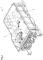
- reference numeral 1 globally indicates a battery charger for vehicles, in particular of the type that can be installed on board of electric, hybrid or similar vehicles and adapted to recharge the battery of the vehicle.
- the battery charger 1 comprises an outer container 2, adapted to house and protect the entire electronics of the battery charger itself and adapted to allow the installation and fixing thereof inside the vehicle.
- the battery charger 1 comprises an electronic appliance, globally indicated with reference numeral 3 in the figures, housed inside the container 2, operatively connectable to an electric battery of a vehicle and configured for the recharge of the battery itself.
- the battery charger also comprises a cooling circuit 4 to limit the temperature of the electronic appliance 3 during the use of the battery charger 1.
- the cooling circuit 4 can be composed of a conventional liquid cooling circuit.
- the cooling circuit 4 is made directly on the bottom of the container 2.
- the electronic appliance 3 comprises at least one electronic board 5 provided with an insulated metal substrate (IMS) 5a associated with the cooling circuit 4.
- IMS insulated metal substrate
- the electronic board 5 also comprises a layer of electrically insulating material 5b made on at least one portion of the insulated metal substrate 5a, and at least one electronic circuit 5c made on the layer of electrically insulating material 5b.
- the electronic appliance 3 may comprise several electronic boards.
- the electronic appliance 3 comprises two electronic boards 5 and 6 wherein, in particular, the electronic board 5 is of the IMS type.
- the electronic board 5 comprises at least one conductive metal bar 7 for the transport and distribution of current, electrically connected to the electronic circuit 5c.
- This conductive metal bar 7 is of the type of a so-called "busbar”, used to allow the transport and distribution of high currents to several different points of an electronic board.
- the conductive metal bar 7 is provided with at least one portion arranged in direct contact with at least one surface portion of the electronic board 5.
- the conductive metal bar 7 can be cooled and, therefore, maintained at a lower working temperature, during the use of the battery charger 1.
- the cooling circuit 4 allows cooling the insulated metal substrate 5a of the electronic board 5 and, by heat conduction, allows cooling the conductive metal bar 7.
- the conductive metal bar 7 is provided with a lower surface arranged in direct contact with at least one surface portion of the electronic board 5.
- the conductive metal bar 7 is substantially plate-shaped and comprises an upper surface opposite the lower surface associated with the electronic board 5.
- the conductive metal bar 7 preferably has a substantially elongated shape.
- the electronic board 5 comprises a plurality of conductive metal bars 7, arranged at different portions of the electronic board itself and adapted to connect different points.
- Each conductive metal bar 7 extends over at least one portion of the electronic board 5, on the layer of electrically insulating material 5b.
- each conductive metal bar 7 comprises electric coupling and connection means 8 of at least one electric connecting element.
- the electric connecting element can be composed e.g. of a special cable adapted to carry a predefined electrical current on the conductive metal bar 7.
- the electric coupling and connection means 8 are composed of an electric terminal made at at least one portion of the conductive metal bar 7.
- the terminal extends from the upper surface of the conductive metal bar 7.
- the electronic board 5 described above is used inside a battery charger 1 for electric vehicles.
- the fact is underlined that the electronic board according to the invention is small in size and, at the same time, simple and quick to assemble.
- the positioning of the conductive metal bar directly on the electronic board together with the fact that the conductive metal bar is cooled by means of the cooling circuit, by heat conduction with the insulated metal substrate of the electronic board itself, allow the use of a conductive metal bar of reduced size compared to the bars of known type.
- the conductive metal bar used precisely because it is cooled down, allows the maintenance of an ideal working temperature in an effective manner.
Landscapes
- Engineering & Computer Science (AREA)
- Microelectronics & Electronic Packaging (AREA)
- Physics & Mathematics (AREA)
- Thermal Sciences (AREA)
- Power Engineering (AREA)
- Charge And Discharge Circuits For Batteries Or The Like (AREA)
- Cooling Or The Like Of Electrical Apparatus (AREA)
- Connection Or Junction Boxes (AREA)
- Electric Propulsion And Braking For Vehicles (AREA)
- Control Of Eletrric Generators (AREA)
- Dry Shavers And Clippers (AREA)
- Current-Collector Devices For Electrically Propelled Vehicles (AREA)
Claims (8)
- Elektronische Platine (5), umfassend ein isoliertes Metallsubstrat (5a), das mit einem Kühlkreislauf (4) in Verbindung bringbar ist, eine Schicht aus elektrisch isolierendem Material (5b), die auf mindestens einem Teil des isolierten Metallsubstrats (5a) aufgebracht ist, mindestens eine elektronische Schaltung (5c), die auf der Schicht aus elektrisch isolierendem Material (5b) aufgebracht ist, und mindestens eine leitende Metallschiene (7) für den Transport und die Verteilung von Strom, die mit der elektronischen Schaltung (5c) elektrisch verbunden und mit einer unteren Fläche versehen ist, die in direktem Kontakt mit mindestens einem Oberflächenabschnitt der elektronischen Platine (5) angeordnet ist,
dadurch gekennzeichnet, dass
die untere Fläche sich über mindestens einen Teil der elektronischen Platine (5) auf der Schicht aus elektrisch isolierendem Material (5b) erstreckt, um die leitende Metallschiene (7) mittels des Kühlkreislaufs (4) zu kühlen. - Elektronische Platine (5) gemäß Anspruch 1, dadurch gekennzeichnet, dass die leitende Metallschiene (7) im Wesentlichen plattenförmig ist.
- Elektronische Platine (5) gemäß einem oder mehreren der vorhergehenden Ansprüche, dadurch gekennzeichnet, dass die leitende Metallschiene (7) eine obere Fläche gegenüber der unteren Fläche aufweist, die mit der elektronischen Platine (5) verbunden ist.
- Elektronische Platine (5) gemäß einem oder mehreren der vorhergehenden Ansprüche, dadurch gekennzeichnet, dass die leitende Metallschiene (7) eine im Wesentlichen längliche Form aufweist.
- Elektronische Platine (5) gemäß einem oder mehreren der vorhergehenden Ansprüche, dadurch gekennzeichnet, dass die leitende Metallschiene (7) elektrische Anschluss- und Verbindungsmittel (8) von mindestens einem elektrischen Verbindungselement umfasst.
- Elektronische Platine (5) gemäß Anspruch 5, dadurch gekennzeichnet, dass die elektrischen Anschluss- und Verbindungsmittel (8) mindestens einen elektrischen Anschluss (8) umfassen, der an mindestens einem Abschnitt der leitenden Metallschiene (7) ausgebildet ist.
- Elektronische Platine (5) gemäß Anspruch 6, dadurch gekennzeichnet, dass sich der mindestens eine elektrische Anschluss (8) von der oberen Fläche der leitenden Metallschiene (7) aus erstreckt.
- Batterieladegerät (1) für Fahrzeuge, umfassend mindestens einen äußeren Behälter (2), mindestens ein elektronisches Gerät (3), das in dem Behälter (2) untergebracht ist, mit einer elektrischen Batterie eines Fahrzeugs funktional verbindbar ist und zum Wiederaufladen der Batterie ausgebildet ist, und mindestens einen Kühlkreislauf (4) für das elektronische Gerät (3),
dadurch gekennzeichnet, dass
das elektronische Gerät (3) mindestens eine elektronische Platine (5) gemäß einem oder mehreren der vorhergehenden Ansprüche umfasst.
Applications Claiming Priority (2)
| Application Number | Priority Date | Filing Date | Title |
|---|---|---|---|
| IT102018000007387A IT201800007387A1 (it) | 2018-07-20 | 2018-07-20 | Caricabatterie per veicoli |
| PCT/IB2019/056170 WO2020016833A1 (en) | 2018-07-20 | 2019-07-18 | Battery charger for vehicles |
Publications (2)
| Publication Number | Publication Date |
|---|---|
| EP3824704A1 EP3824704A1 (de) | 2021-05-26 |
| EP3824704B1 true EP3824704B1 (de) | 2025-06-18 |
Family
ID=63834555
Family Applications (1)
| Application Number | Title | Priority Date | Filing Date |
|---|---|---|---|
| EP19772856.1A Active EP3824704B1 (de) | 2018-07-20 | 2019-07-18 | Batterieladegerät für fahrzeuge |
Country Status (6)
| Country | Link |
|---|---|
| US (1) | US11700715B2 (de) |
| EP (1) | EP3824704B1 (de) |
| JP (1) | JP7496346B2 (de) |
| CN (1) | CN110733361B (de) |
| IT (1) | IT201800007387A1 (de) |
| WO (1) | WO2020016833A1 (de) |
Families Citing this family (5)
| Publication number | Priority date | Publication date | Assignee | Title |
|---|---|---|---|---|
| CN111404216B (zh) * | 2020-03-10 | 2023-03-31 | 安徽潜川动力锂电科技有限公司 | 一种防摔智能充电宝 |
| CN113246764B (zh) * | 2021-05-12 | 2023-03-24 | 美达电器(重庆)有限公司 | 一种充电机 |
| USD1101671S1 (en) * | 2022-09-08 | 2025-11-11 | Harbinger Motors Inc. | Battery pack |
| CN118358398A (zh) * | 2023-01-18 | 2024-07-19 | 华为数字能源技术有限公司 | 车载供电装置及车辆 |
| CN118596931B (zh) * | 2024-06-18 | 2024-12-03 | 南京金龙客车制造有限公司 | 快速充电装置和新能源重卡牵引车 |
Citations (1)
| Publication number | Priority date | Publication date | Assignee | Title |
|---|---|---|---|---|
| US20060039127A1 (en) * | 2004-08-19 | 2006-02-23 | Distributed Power, Inc. | High power density insulated metal substrate based power converter assembly with very low BUS impedance |
Family Cites Families (25)
| Publication number | Priority date | Publication date | Assignee | Title |
|---|---|---|---|---|
| ES2187280B1 (es) * | 2001-06-28 | 2004-08-16 | Lear Automotive (Eeds) Spain, S.L. | Placa de circuito impreso con substrato metalico aislado con sistema de refrigeracion integrado. |
| US7187548B2 (en) * | 2002-01-16 | 2007-03-06 | Rockwell Automation Technologies, Inc. | Power converter having improved fluid cooling |
| US6865080B2 (en) * | 2002-01-16 | 2005-03-08 | Rockwell Automation Technologies, Inc. | Compact fluid cooled power converter supporting multiple circuit boards |
| DE102006028675B4 (de) * | 2006-06-22 | 2008-08-21 | Siemens Ag | Kühlanordnung für auf einer Trägerplatte angeordnete elektrische Bauelemente |
| JP4452952B2 (ja) * | 2007-06-20 | 2010-04-21 | 日立オートモティブシステムズ株式会社 | 電力変換装置 |
| JP4452953B2 (ja) * | 2007-08-09 | 2010-04-21 | 日立オートモティブシステムズ株式会社 | 電力変換装置 |
| JP2011124244A (ja) * | 2008-04-24 | 2011-06-23 | Denki Kagaku Kogyo Kk | 絶縁金属ベース回路基板及びそれを用いた混成集積回路モジュール |
| JP5238380B2 (ja) * | 2008-07-07 | 2013-07-17 | 本田技研工業株式会社 | 電源装置のハンダ接合構造およびその接合方法 |
| DE102008048005B3 (de) * | 2008-09-19 | 2010-04-08 | Infineon Technologies Ag | Leistungshalbleitermodulanordnung und Verfahren zur Herstellung einer Leistungshalbleitermodulanordnung |
| DE102009053998A1 (de) * | 2009-11-19 | 2011-05-26 | Still Gmbh | Umrichter, insbesondere mehrphasiger Drehstromumrichter |
| WO2011083578A1 (ja) * | 2010-01-08 | 2011-07-14 | トヨタ自動車株式会社 | 半導体モジュール |
| JP5646242B2 (ja) * | 2010-07-28 | 2014-12-24 | Fdkトワイセル株式会社 | 回路基板装置 |
| JP2013099119A (ja) * | 2011-10-31 | 2013-05-20 | Sanyo Electric Co Ltd | 充電器 |
| ITMO20110325A1 (it) * | 2011-12-15 | 2013-06-16 | Meta System Spa | Procedimento per la realizzazione di caricabatterie per veicoli e caricabatterie cosi' ottenibile |
| JP6135543B2 (ja) * | 2014-02-19 | 2017-05-31 | 株式会社デンソー | 電源装置 |
| JP6260566B2 (ja) * | 2015-03-25 | 2018-01-17 | 株式会社オートネットワーク技術研究所 | 回路構成体 |
| DE102015113873B3 (de) * | 2015-08-21 | 2016-07-14 | Semikron Elektronik Gmbh & Co. Kg | Leistungselektronische Baugruppe mit Kondensatoreinrichtung |
| JP2017127097A (ja) * | 2016-01-13 | 2017-07-20 | 株式会社デンソー | 制御装置一体型回転電機 |
| JP7145075B2 (ja) * | 2016-02-24 | 2022-09-30 | ヒタチ・エナジー・スウィツァーランド・アクチェンゲゼルシャフト | 多層回路基板に基づくパワーモジュール |
| JP6814612B2 (ja) * | 2016-06-02 | 2021-01-20 | 矢崎総業株式会社 | 車両のアース配索構造 |
| DE102016112777B4 (de) * | 2016-07-12 | 2021-03-18 | Semikron Elektronik Gmbh & Co. Kg | Leistungshalbleitereinrichtung |
| KR102638979B1 (ko) * | 2016-12-21 | 2024-02-22 | 현대자동차주식회사 | 전력 모듈, 그의 제조 방법 및 그를 가지는 차량 |
| DE102017003854A1 (de) * | 2017-04-20 | 2018-10-25 | Leopold Kostal Gmbh & Co. Kg | Gehäuse für ein elektrisches oder elektronisches Gerät |
| IT201700070324A1 (it) * | 2017-06-23 | 2018-12-23 | Meta System Spa | Apparecchiatura elettronica di potenza per auto elettriche o ibride e relativo procedimento di realizzazione |
| US10394292B1 (en) * | 2018-06-11 | 2019-08-27 | Microsoft Technology Licensing, Llc | Cryogenic computing system with thermal management using a metal preform |
-
2018
- 2018-07-20 IT IT102018000007387A patent/IT201800007387A1/it unknown
-
2019
- 2019-03-08 CN CN201910173921.0A patent/CN110733361B/zh active Active
- 2019-07-18 EP EP19772856.1A patent/EP3824704B1/de active Active
- 2019-07-18 US US17/261,808 patent/US11700715B2/en active Active
- 2019-07-18 WO PCT/IB2019/056170 patent/WO2020016833A1/en not_active Ceased
- 2019-07-18 JP JP2021502753A patent/JP7496346B2/ja active Active
Patent Citations (1)
| Publication number | Priority date | Publication date | Assignee | Title |
|---|---|---|---|---|
| US20060039127A1 (en) * | 2004-08-19 | 2006-02-23 | Distributed Power, Inc. | High power density insulated metal substrate based power converter assembly with very low BUS impedance |
Also Published As
| Publication number | Publication date |
|---|---|
| CN110733361A (zh) | 2020-01-31 |
| EP3824704A1 (de) | 2021-05-26 |
| IT201800007387A1 (it) | 2020-01-20 |
| US20210298209A1 (en) | 2021-09-23 |
| JP7496346B2 (ja) | 2024-06-06 |
| JP2021530957A (ja) | 2021-11-11 |
| WO2020016833A1 (en) | 2020-01-23 |
| US11700715B2 (en) | 2023-07-11 |
| CN110733361B (zh) | 2025-02-14 |
Similar Documents
| Publication | Publication Date | Title |
|---|---|---|
| EP3824704B1 (de) | Batterieladegerät für fahrzeuge | |
| US11276536B2 (en) | Power relay assembly | |
| US10128722B2 (en) | Electrical connection structure, terminal structure, and vehicle | |
| US10179557B2 (en) | Multi-voltage on-board electrical system and multilayer cable for different voltage levels | |
| US11451118B2 (en) | Conductor arrangement and transportable electrical drive device | |
| US20090066289A1 (en) | Battery charger with a planar bus | |
| US20180219305A1 (en) | High power module interfaces | |
| EP2792045B1 (de) | Verfahren zur herstellung von batterieladevorrichtungen für fahrzeuge und in diesem verfahren hergestellte batterieladevorrichtungen | |
| US10103521B2 (en) | Electrical power distribution plate comprising a protected distribution bar | |
| US20150331058A1 (en) | Voltage detecting device | |
| US20170149288A1 (en) | Wireless transmission device | |
| KR101901134B1 (ko) | 무선급전 선로에 연결되는 캐패시터 함체 구조 | |
| KR20160040865A (ko) | 차량 내의 금속 인쇄회로기판 실장용 버스 바 | |
| US20190009684A1 (en) | Power system | |
| CN106465534A (zh) | 大电流开关 | |
| CN109841980B (zh) | 电压转换器、公电连接器及其制造方法 | |
| EP3296174B1 (de) | Fahrzeugsteuerungsvorrichtung | |
| EP3824701B1 (de) | Batterieladegerät für fahrzeuge und zugehöriges herstellungsverfahren | |
| JP2022190189A (ja) | スイッチング装置 | |
| JP2018076013A5 (de) | ||
| EP3056834B1 (de) | Elektrische Heizeinrichtung | |
| US20250164317A1 (en) | Temperature measuring system for power semiconductors arranged on a base plate of an inverter | |
| WO2018054453A1 (en) | An electrical junction box | |
| CN117730630A (zh) | 电压转换系统和用于制造这种电压转换系统的方法 | |
| KR20250176535A (ko) | 전지 모듈, 전지 모듈에 대한 모니터링 기능을 제공하는 방법, 전지 시스템 및 전기 차량 |
Legal Events
| Date | Code | Title | Description |
|---|---|---|---|
| STAA | Information on the status of an ep patent application or granted ep patent |
Free format text: STATUS: UNKNOWN |
|
| STAA | Information on the status of an ep patent application or granted ep patent |
Free format text: STATUS: THE INTERNATIONAL PUBLICATION HAS BEEN MADE |
|
| PUAI | Public reference made under article 153(3) epc to a published international application that has entered the european phase |
Free format text: ORIGINAL CODE: 0009012 |
|
| STAA | Information on the status of an ep patent application or granted ep patent |
Free format text: STATUS: REQUEST FOR EXAMINATION WAS MADE |
|
| 17P | Request for examination filed |
Effective date: 20210218 |
|
| AK | Designated contracting states |
Kind code of ref document: A1 Designated state(s): AL AT BE BG CH CY CZ DE DK EE ES FI FR GB GR HR HU IE IS IT LI LT LU LV MC MK MT NL NO PL PT RO RS SE SI SK SM TR |
|
| DAV | Request for validation of the european patent (deleted) | ||
| DAX | Request for extension of the european patent (deleted) | ||
| STAA | Information on the status of an ep patent application or granted ep patent |
Free format text: STATUS: EXAMINATION IS IN PROGRESS |
|
| 17Q | First examination report despatched |
Effective date: 20230515 |
|
| P01 | Opt-out of the competence of the unified patent court (upc) registered |
Effective date: 20230527 |
|
| GRAP | Despatch of communication of intention to grant a patent |
Free format text: ORIGINAL CODE: EPIDOSNIGR1 |
|
| STAA | Information on the status of an ep patent application or granted ep patent |
Free format text: STATUS: GRANT OF PATENT IS INTENDED |
|
| INTG | Intention to grant announced |
Effective date: 20240906 |
|
| GRAS | Grant fee paid |
Free format text: ORIGINAL CODE: EPIDOSNIGR3 |
|
| GRAA | (expected) grant |
Free format text: ORIGINAL CODE: 0009210 |
|
| STAA | Information on the status of an ep patent application or granted ep patent |
Free format text: STATUS: THE PATENT HAS BEEN GRANTED |
|
| AK | Designated contracting states |
Kind code of ref document: B1 Designated state(s): AL AT BE BG CH CY CZ DE DK EE ES FI FR GB GR HR HU IE IS IT LI LT LU LV MC MK MT NL NO PL PT RO RS SE SI SK SM TR |
|
| REG | Reference to a national code |
Ref country code: GB Ref legal event code: FG4D |
|
| REG | Reference to a national code |
Ref country code: CH Ref legal event code: EP |
|
| REG | Reference to a national code |
Ref country code: DE Ref legal event code: R096 Ref document number: 602019071282 Country of ref document: DE |
|
| REG | Reference to a national code |
Ref country code: CH Ref legal event code: EP |
|
| REG | Reference to a national code |
Ref country code: IE Ref legal event code: FG4D |
|
| PG25 | Lapsed in a contracting state [announced via postgrant information from national office to epo] |
Ref country code: FI Free format text: LAPSE BECAUSE OF FAILURE TO SUBMIT A TRANSLATION OF THE DESCRIPTION OR TO PAY THE FEE WITHIN THE PRESCRIBED TIME-LIMIT Effective date: 20250618 |
|
| PGFP | Annual fee paid to national office [announced via postgrant information from national office to epo] |
Ref country code: DE Payment date: 20250901 Year of fee payment: 7 |
|
| REG | Reference to a national code |
Ref country code: LT Ref legal event code: MG9D |
|
| PG25 | Lapsed in a contracting state [announced via postgrant information from national office to epo] |
Ref country code: NO Free format text: LAPSE BECAUSE OF FAILURE TO SUBMIT A TRANSLATION OF THE DESCRIPTION OR TO PAY THE FEE WITHIN THE PRESCRIBED TIME-LIMIT Effective date: 20250918 Ref country code: GR Free format text: LAPSE BECAUSE OF FAILURE TO SUBMIT A TRANSLATION OF THE DESCRIPTION OR TO PAY THE FEE WITHIN THE PRESCRIBED TIME-LIMIT Effective date: 20250919 |
|
| PGFP | Annual fee paid to national office [announced via postgrant information from national office to epo] |
Ref country code: IT Payment date: 20250917 Year of fee payment: 7 |
|
| PG25 | Lapsed in a contracting state [announced via postgrant information from national office to epo] |
Ref country code: BG Free format text: LAPSE BECAUSE OF FAILURE TO SUBMIT A TRANSLATION OF THE DESCRIPTION OR TO PAY THE FEE WITHIN THE PRESCRIBED TIME-LIMIT Effective date: 20250618 |
|
| PGFP | Annual fee paid to national office [announced via postgrant information from national office to epo] |
Ref country code: GB Payment date: 20250909 Year of fee payment: 7 |
|
| PG25 | Lapsed in a contracting state [announced via postgrant information from national office to epo] |
Ref country code: HR Free format text: LAPSE BECAUSE OF FAILURE TO SUBMIT A TRANSLATION OF THE DESCRIPTION OR TO PAY THE FEE WITHIN THE PRESCRIBED TIME-LIMIT Effective date: 20250618 |
|
| PGFP | Annual fee paid to national office [announced via postgrant information from national office to epo] |
Ref country code: FR Payment date: 20250829 Year of fee payment: 7 |
|
| PG25 | Lapsed in a contracting state [announced via postgrant information from national office to epo] |
Ref country code: RS Free format text: LAPSE BECAUSE OF FAILURE TO SUBMIT A TRANSLATION OF THE DESCRIPTION OR TO PAY THE FEE WITHIN THE PRESCRIBED TIME-LIMIT Effective date: 20250918 |
|
| REG | Reference to a national code |
Ref country code: NL Ref legal event code: MP Effective date: 20250618 |
|
| PG25 | Lapsed in a contracting state [announced via postgrant information from national office to epo] |
Ref country code: LV Free format text: LAPSE BECAUSE OF FAILURE TO SUBMIT A TRANSLATION OF THE DESCRIPTION OR TO PAY THE FEE WITHIN THE PRESCRIBED TIME-LIMIT Effective date: 20250618 |
|
| PG25 | Lapsed in a contracting state [announced via postgrant information from national office to epo] |
Ref country code: NL Free format text: LAPSE BECAUSE OF FAILURE TO SUBMIT A TRANSLATION OF THE DESCRIPTION OR TO PAY THE FEE WITHIN THE PRESCRIBED TIME-LIMIT Effective date: 20250618 |
|
| PG25 | Lapsed in a contracting state [announced via postgrant information from national office to epo] |
Ref country code: PT Free format text: LAPSE BECAUSE OF FAILURE TO SUBMIT A TRANSLATION OF THE DESCRIPTION OR TO PAY THE FEE WITHIN THE PRESCRIBED TIME-LIMIT Effective date: 20251020 |
|
| REG | Reference to a national code |
Ref country code: AT Ref legal event code: MK05 Ref document number: 1805414 Country of ref document: AT Kind code of ref document: T Effective date: 20250618 |
|
| PG25 | Lapsed in a contracting state [announced via postgrant information from national office to epo] |
Ref country code: IS Free format text: LAPSE BECAUSE OF FAILURE TO SUBMIT A TRANSLATION OF THE DESCRIPTION OR TO PAY THE FEE WITHIN THE PRESCRIBED TIME-LIMIT Effective date: 20251018 |
|
| REG | Reference to a national code |
Ref country code: DE Ref legal event code: R081 Ref document number: 602019071282 Country of ref document: DE Owner name: META ELECTRONICS S.R.L., ALTO RENE TERME, IT Free format text: FORMER OWNER: META SYSTEM S.P.A., REGGIO EMILIA, IT Ref country code: DE Ref legal event code: R081 Ref document number: 602019071282 Country of ref document: DE Owner name: META ELECTRONICS S.R.L., ALTO RENO TERME, IT Free format text: FORMER OWNER: META SYSTEM S.P.A., REGGIO EMILIA, IT |
|
| PG25 | Lapsed in a contracting state [announced via postgrant information from national office to epo] |
Ref country code: AT Free format text: LAPSE BECAUSE OF FAILURE TO SUBMIT A TRANSLATION OF THE DESCRIPTION OR TO PAY THE FEE WITHIN THE PRESCRIBED TIME-LIMIT Effective date: 20250618 Ref country code: SM Free format text: LAPSE BECAUSE OF FAILURE TO SUBMIT A TRANSLATION OF THE DESCRIPTION OR TO PAY THE FEE WITHIN THE PRESCRIBED TIME-LIMIT Effective date: 20250618 |
|
| PG25 | Lapsed in a contracting state [announced via postgrant information from national office to epo] |
Ref country code: CZ Free format text: LAPSE BECAUSE OF FAILURE TO SUBMIT A TRANSLATION OF THE DESCRIPTION OR TO PAY THE FEE WITHIN THE PRESCRIBED TIME-LIMIT Effective date: 20250618 |
|
| PG25 | Lapsed in a contracting state [announced via postgrant information from national office to epo] |
Ref country code: PL Free format text: LAPSE BECAUSE OF FAILURE TO SUBMIT A TRANSLATION OF THE DESCRIPTION OR TO PAY THE FEE WITHIN THE PRESCRIBED TIME-LIMIT Effective date: 20250618 |
|
| PG25 | Lapsed in a contracting state [announced via postgrant information from national office to epo] |
Ref country code: EE Free format text: LAPSE BECAUSE OF FAILURE TO SUBMIT A TRANSLATION OF THE DESCRIPTION OR TO PAY THE FEE WITHIN THE PRESCRIBED TIME-LIMIT Effective date: 20250618 |
|
| PG25 | Lapsed in a contracting state [announced via postgrant information from national office to epo] |
Ref country code: SK Free format text: LAPSE BECAUSE OF FAILURE TO SUBMIT A TRANSLATION OF THE DESCRIPTION OR TO PAY THE FEE WITHIN THE PRESCRIBED TIME-LIMIT Effective date: 20250618 Ref country code: RO Free format text: LAPSE BECAUSE OF FAILURE TO SUBMIT A TRANSLATION OF THE DESCRIPTION OR TO PAY THE FEE WITHIN THE PRESCRIBED TIME-LIMIT Effective date: 20250618 |
|
| PG25 | Lapsed in a contracting state [announced via postgrant information from national office to epo] |
Ref country code: ES Free format text: LAPSE BECAUSE OF FAILURE TO SUBMIT A TRANSLATION OF THE DESCRIPTION OR TO PAY THE FEE WITHIN THE PRESCRIBED TIME-LIMIT Effective date: 20250618 |
|
| REG | Reference to a national code |
Ref country code: GB Ref legal event code: 732E Free format text: REGISTERED BETWEEN 20260108 AND 20260114 |
|
| REG | Reference to a national code |
Ref country code: CH Ref legal event code: H13 Free format text: ST27 STATUS EVENT CODE: U-0-0-H10-H13 (AS PROVIDED BY THE NATIONAL OFFICE) Effective date: 20260224 |
|
| PG25 | Lapsed in a contracting state [announced via postgrant information from national office to epo] |
Ref country code: LU Free format text: LAPSE BECAUSE OF NON-PAYMENT OF DUE FEES Effective date: 20250718 |
|
| REG | Reference to a national code |
Ref country code: BE Ref legal event code: MM Effective date: 20250731 |
|
| PG25 | Lapsed in a contracting state [announced via postgrant information from national office to epo] |
Ref country code: MC Free format text: LAPSE BECAUSE OF FAILURE TO SUBMIT A TRANSLATION OF THE DESCRIPTION OR TO PAY THE FEE WITHIN THE PRESCRIBED TIME-LIMIT Effective date: 20250618 |
|
| PG25 | Lapsed in a contracting state [announced via postgrant information from national office to epo] |
Ref country code: DK Free format text: LAPSE BECAUSE OF FAILURE TO SUBMIT A TRANSLATION OF THE DESCRIPTION OR TO PAY THE FEE WITHIN THE PRESCRIBED TIME-LIMIT Effective date: 20250618 |
|
| PG25 | Lapsed in a contracting state [announced via postgrant information from national office to epo] |
Ref country code: BE Free format text: LAPSE BECAUSE OF NON-PAYMENT OF DUE FEES Effective date: 20250731 |
|
| REG | Reference to a national code |
Ref country code: DE Ref legal event code: R081 Ref document number: 602019071282 Country of ref document: DE Owner name: META ELECTRONICS S.R.L., ALTO RENO TERME, IT Free format text: FORMER OWNER: META ELECTRONICS S.R.L., ALTO RENE TERME, BO, IT |
|
| PG25 | Lapsed in a contracting state [announced via postgrant information from national office to epo] |
Ref country code: CH Free format text: LAPSE BECAUSE OF NON-PAYMENT OF DUE FEES Effective date: 20250731 |
|
| PLBE | No opposition filed within time limit |
Free format text: ORIGINAL CODE: 0009261 |
|
| STAA | Information on the status of an ep patent application or granted ep patent |
Free format text: STATUS: NO OPPOSITION FILED WITHIN TIME LIMIT |
|
| REG | Reference to a national code |
Ref country code: CH Ref legal event code: L10 Free format text: ST27 STATUS EVENT CODE: U-0-0-L10-L00 (AS PROVIDED BY THE NATIONAL OFFICE) Effective date: 20260430 |