EP3824718B1 - Gartensprinkler mit düsensteuerungssystem - Google Patents
Gartensprinkler mit düsensteuerungssystem Download PDFInfo
- Publication number
- EP3824718B1 EP3824718B1 EP19210487.5A EP19210487A EP3824718B1 EP 3824718 B1 EP3824718 B1 EP 3824718B1 EP 19210487 A EP19210487 A EP 19210487A EP 3824718 B1 EP3824718 B1 EP 3824718B1
- Authority
- EP
- European Patent Office
- Prior art keywords
- adjusting
- base
- main body
- upper cover
- main
- Prior art date
- Legal status (The legal status is an assumption and is not a legal conclusion. Google has not performed a legal analysis and makes no representation as to the accuracy of the status listed.)
- Not-in-force
Links
Images





Classifications
-
- A—HUMAN NECESSITIES
- A01—AGRICULTURE; FORESTRY; ANIMAL HUSBANDRY; HUNTING; TRAPPING; FISHING
- A01G—HORTICULTURE; CULTIVATION OF VEGETABLES, FLOWERS, RICE, FRUIT, VINES, HOPS OR SEAWEED; FORESTRY; WATERING
- A01G25/00—Watering gardens, fields, sports grounds or the like
-
- B—PERFORMING OPERATIONS; TRANSPORTING
- B05—SPRAYING OR ATOMISING IN GENERAL; APPLYING FLUENT MATERIALS TO SURFACES, IN GENERAL
- B05B—SPRAYING APPARATUS; ATOMISING APPARATUS; NOZZLES
- B05B15/00—Details of spraying plant or spraying apparatus not otherwise provided for; Accessories
- B05B15/60—Arrangements for mounting, supporting or holding spraying apparatus
- B05B15/65—Mounting arrangements for fluid connection of the spraying apparatus or its outlets to flow conduits
- B05B15/652—Mounting arrangements for fluid connection of the spraying apparatus or its outlets to flow conduits whereby the jet can be oriented
-
- B—PERFORMING OPERATIONS; TRANSPORTING
- B05—SPRAYING OR ATOMISING IN GENERAL; APPLYING FLUENT MATERIALS TO SURFACES, IN GENERAL
- B05B—SPRAYING APPARATUS; ATOMISING APPARATUS; NOZZLES
- B05B15/00—Details of spraying plant or spraying apparatus not otherwise provided for; Accessories
- B05B15/60—Arrangements for mounting, supporting or holding spraying apparatus
- B05B15/68—Arrangements for adjusting the position of spray heads
-
- B—PERFORMING OPERATIONS; TRANSPORTING
- B05—SPRAYING OR ATOMISING IN GENERAL; APPLYING FLUENT MATERIALS TO SURFACES, IN GENERAL
- B05B—SPRAYING APPARATUS; ATOMISING APPARATUS; NOZZLES
- B05B3/00—Spraying or sprinkling apparatus with moving outlet elements or moving deflecting elements
- B05B3/02—Spraying or sprinkling apparatus with moving outlet elements or moving deflecting elements with rotating elements
- B05B3/04—Spraying or sprinkling apparatus with moving outlet elements or moving deflecting elements with rotating elements driven by the liquid or other fluent material discharged, e.g. the liquid actuating a motor before passing to the outlet
- B05B3/0417—Spraying or sprinkling apparatus with moving outlet elements or moving deflecting elements with rotating elements driven by the liquid or other fluent material discharged, e.g. the liquid actuating a motor before passing to the outlet comprising a liquid driven rotor, e.g. a turbine
- B05B3/0432—Spraying or sprinkling apparatus with moving outlet elements or moving deflecting elements with rotating elements driven by the liquid or other fluent material discharged, e.g. the liquid actuating a motor before passing to the outlet comprising a liquid driven rotor, e.g. a turbine the rotation of the outlet elements being reversible
- B05B3/0438—Tubular elements holding several outlets, e.g. apertured tubes, oscillating about an axis substantially parallel to the tubular element
Definitions
- the present invention relates to a garden sprinkler, and more particularly to a garden sprinkler with a nozzle control system capable of adjusting the spray in a concentrated or fan-shaped pattern according to the area to be sprinkled.
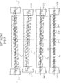
- a conventional spraying device 60 as shown in FIGs. 9-11 , has a nozzle device 61 and an adjusting device.
- the nozzle device 61 is capable of being connected to a liquid supply source and provided with a plurality of nozzles 62.
- the adjusting device is used for adjusting the direction of the nozzle device 61, so that the nozzles 62 are adjustable and positionable.
- the adjusting device further comprises a first guiding member 63 having a plurality of first guiding openings 631 and a second guiding member 64 having a plurality of second guiding openings 641.
- the second guiding member 64 is capable of moving relatively to the first guiding member 63 With translational movements of the first guiding member 63 and the second guiding member 64, the first guiding openings 631 and the second guiding openings 641 can be arranged in staggered manner to different degrees.
- a left slider 65 and a right slider 66 are provided at the two ends of the adjusting device and configured to be operated respectively for adjusting the spray direction and the spray density of the nozzles 62.
- the conventional spraying device 60 as described above still has the following problems: In order to adjust the spray direction and the spray density of the nozzles 62, the first guiding openings 631 and the second guiding openings 641 need to be arranged in a proper staggered manner. Thereafter, the left and right sliders 65, 66 need to be operated respectively according to requirements, which is costly in terms of time and labor. In addition, since several different parts of the spraying device 60 need to be adjusted separately, it may happen that the water is not sprayed equally after the adjustment.
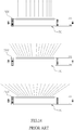
- FIGs. 12-14 another conventional sprayer, as shown in the FIGs. 12-14 , includes a main body 70, a nozzle driving device, and a nozzle cover 73.
- the main body 0 has a tubular shape.
- a water inlet 702 and a plurality of nozzle-receiving openings 701 are provided inside the main body 70.
- the water inlet 702 is disposed at one end of the sprayer, and the nozzle-receiving openings 701 are arranged on the transverse upper side of the main body 70 in such a way that nozzle shafts 711 are capable of being inserted in the nozzle-receiving openings 701 correspondingly and then secured therein.
- the main body 70 Two sides of the main body 70 are provided with corresponding ribs 703 for engaging with lips 732 of the nozzle cover 73.
- the a nozzle driving device comprising a plurality of nozzles 71 connected by a strip and a arc-shaped adjusting member 72.
- the arc-shaped adjusting member 72 is provided with a plurality of oblique adjusting openings 721 arranged in different directions and distributed then in a fan-shape.
- the nozzles 71 will be adjusted in one single stage in such a manner that they are gradually inclined and arranged in a fan-shape, achieving a fan-shaped pattern of equally sprayed water.
- the nozzle cover 73 has a semi-circular vertical section, whereas a plurality holes 731 is arranged on one side of the nozzle cover 73 transversely and configured in such a way that the water outlet of the respective nozzle 71 is just capable of being inserted through the corresponding hole 731 and movably disposed therein.
- Two sides of the bottom of the nozzle cover 73 are bent inwardly as rims 732, and the nozzle cover 73 is to be put on the adjusting member 72 and the nozzles 71 for covering the adjusting member 72 and the nozzles 71.
- the nozzle cover 73 is combined with the main body 70.
- the conventional sprayer as described above still has the following problems: (i) Since the arc-shaped adjusting member 72 is pivoted by operating an adjusting ring 722 provided at one end of the arc-shaped adjusting member 72, the application of force tends towards to one single side of the arc-shaped adjusting member 72. Thus, it is not possible for the nozzle driving device to apply a force to the arc-shaped adjusting member 72 equally.
- An objective of present invention is to provide a garden sprinkler with nozzle control system, with which a time- and effort-saving operation and a pattern of equally and densely sprayed water can be achieved.
- the garden sprinkler has the features of claim 1. Further embodiments are subject-matter of the dependent claims.
- the garden sprinkler comprises a main body, a spraying unit, at least one adjusting base, and at least one driving member.
- the main body has a main base and an upper cover mating with each other.
- the main base is hollow, tube-shaped inwardly and has an assembly opening at an end thereof.
- the spraying unit is put into the main base through the assembly opening, and a hose coupling is mounted in the assembly opening.
- a recess and a sprinkling surface are formed on the main base downwards in sequence.
- a plurality of first through apertures and a plurality of second through apertures are arranged axially on corresponding positions of the sprinkling surface and the upper cover, whereas the length of the second through apertures increases gradually from the middle to the both ends of the upper cover.
- the adjusting base is put in the recess and the upper cover is put on and thus mated with the main base as to close the recess.
- the corresponding middle section of the front and rear sides of the main body is formed in such a way that at least one passageway is formed by the main base and the upper cover.
- the passageway is provided with a stop baffle configured to stop the driving member by permitting it only to idle on the main body when a screw of the driving member is inserted through the passageway, but not to be released from the same..
- the spraying unit includes a plurality of nozzles coupled with each other by means of a connecting strip.
- the spraying unit is put into the main base through the assembly opening and the nozzles are inserted through the corresponding first and second through apertures.
- the nozzles are disposed accordingly and protrude from the upper cover and the connecting strip abuts against the sprinkling surface arranged inside the main base.
- a plurality of adjusting long holes extending forwards and backwards is arranged radially on the upper surface of the adjusting base.
- the adjusting long holes are differently inclined from the middle point to the both ends of the adjusting base.
- a screw hole is arranged in the middle part of the adjusting base, extending through the adjusting base.
- the adjusting base is arranged in the recess between the main base and the upper cover.
- the screw hole is aligned with the passageway accurately and the nozzles are inserted at first through the adjusting long holes and then through the second through apertures, protruding from the main body.
- the driving member has a knob, and a screw is connected to the middle portion of the rear end of the knob.
- a stop groove is arranged on the screw, being adjacent to the knob.
- the driving member is inserted in the passageway and screwed with the screw hole and the stop baffle is pressed to snap in the stop groove while putting the upper cover on the main base.
- the driving member is permitted only to idle on the main body, but not to be released from the same.
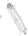
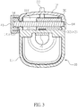
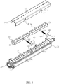
- a garden sprinkler with nozzle control system comprises a main body 10, a spraying unit 20, at least one adjusting base 30, and at least one driving member 40.
- the main body 10 has a main base 11 and an upper cover 12 mating with each other.
- the main base 11 is hollow, tube-shaped inwardly and has an assembly opening 111 at an end thereof.
- the spraying unit 20 is to be put into the main base 11 through the assembly opening 111, and a hose coupling 13 is to be mounted in the assembly opening 111.
- a recess 112 and a sprinkling surface 113 are formed on the main base 11 downwards in sequence.
- a plurality of first through apertures 114 and a plurality of second through apertures 121 are arranged axially on corresponding positions of the sprinkling surface 113 and the upper cover 12, whereas the length of the second through apertures 121 increases gradually from the middle to the both ends of the upper cover 12.
- the upper cover 12 is to be put on and thus mated with the main base 11 as to close the recess 112.
- the corresponding middle section of the front and rear sides of the main body 10 is formed in such a way that at least one passageway 14 is being formed by combining the main base 11 and the upper cover 12 with each other.
- the passageway 14 is provided with a stop baffle 141.
- the spraying unit 20 includes a plurality of nozzle 22 coupled with each other by means of a connecting strip 21. As soon as the spraying unit 20 is put into the main base 11 through the assembly opening 111, the nozzles 22 are capable of being inserted through the corresponding first and second through apertures 114 and 121. When the nozzles 22 are disposed accordingly and protrude from the upper cover, the connecting strip 21 abuts against the sprinkling surface 113 arranged inside the main base 11.
- a plurality of adjusting long holes 31 extending forwards and backwards is arranged radially on the upper surface of the adjusting base 30 in such a manner that the adjusting long holes 31 are differently inclined from the middle point to the both ends of the adjusting base 30.
- a screw hole 32 is arranged in the middle part of the adjusting base 30, extending through the same.
- the driving member 40 has a knob 41, and a screw 42 is connected to the middle portion of the rear end of the knob 41.
- a stop groove 43 is arranged on the screw 42, being adjacent to the knob 41.
- the main base 11 and the upper cover 12 are connected with each other by snap-fit.
- the respective nozzle 22 further comprises an input end extending through the connecting strip 21 and an output end capable of being inserted through the corresponding first through aperture 114, corresponding adjusting long hole 31, and the corresponding second through aperture 121 in sequence, whereas hole diameter of the input end is larger than that of the output end.
- a neck portion 221 is disposed on the respective nozzle 22, being adjacent to the connecting strip 21, and the rim of the respective first through aperture 114 of the main base 11 is to be pushed to snap in the neck portion 221 as to secure the spraying unit 20 on the main base 11 well.
- the nozzles 22 are made of rubber or suchlike and thus elastic.
- the adjusting base 30 is a hollow housing whose opening faces downwardly.
- the main body 10 is configured to be placed directly on the ground, as shown in FIGs. 1 to 6 .
- the main body 10 is to be used together with a bottom base 50, as shown in FIG. 7 , allowing the main body 10 to pivot on the bottom base 50 synchronously while sprinkling water.
- the corresponding middle section of the front and rear sides of the main body 10 is formed in such a way that the passageway 14 is being formed by combining the main base 11 and the upper cover 12 with each other.
- the passageway 14 is configured to receive the driving member 40.
- two adjacent adjusting bases 30 are disposed in the recess 112 of the main body 10.
- the adjusting long holes 31 formed on the two adjusting bases 30 are arranged radially on the upper surface of the adjusting bases 30 in such a manner that the adjusting long holes 31 are differently inclined from the middle section of an unity consisting of the two adjusting bases 30 to the both outer ends of the unit consisting of these two adjusting bases 30.
- a screw hole 32 is arranged in the middle part of the respective adjusting base 30, extending through the same.
- the corresponding screw 42 of the driving member 40 pivotably mounted on the main body 10 is to be screwed into the screw hole 32, as shown in FIG. 8 .
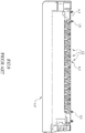
- the adjusting base 30 can be caused to translationally move forwards and backwards by rotating the knob 41 clockwise and counterclockwise. While the adjusting base 30 moves translationally, different portions of the adjusting long holes 31 abut against the nozzles 22, causing the nozzles 22 to swing to different grades, as shown in FIG. 5 and FIG. 6 .
- the nozzle control system is capable of adjusting the spray in a concentrated or fan-shaped pattern according to the area to be sprinkled.
- the knob 41 needs to be rotated only once, thereby achieving a more time-saving, labor-saving and convenient operation.
- the adjustment of the nozzles 22 can be completed by rotating the knob 41 one time, the problem that different adjusting parts cannot work together precisely and a pattern of equally sprinkled water is not achievable after the adjustment due to the poor cooperation of the different adjusting parts does not exist.
- the adjustment of the nozzles 22 is executed by the rotation of the driving member 40 in the middle part of the adjusting base 30 and can be completed quickly in a single operation, it won't happen that the application of force tends towards to one single side of the adjusting base 30.
- the nozzles 22 move along the adjusting long holes 31 linearly, achieving a desired lateral pull with the shortest movement distance. Thereby, the adjustment of the nozzles 22 can be executed more accurately and a pattern of more equally and densely sprinkled water is achievable.
Landscapes
- Engineering & Computer Science (AREA)
- Water Supply & Treatment (AREA)
- Life Sciences & Earth Sciences (AREA)
- Environmental Sciences (AREA)
- Nozzles (AREA)
- Catching Or Destruction (AREA)
Claims (10)
- Gartensprinkler mit einem Düsensteuersystem, umfassend einen Hauptkörper (10), eine Sprüheinheit (20), mindestens eine Justierbasis (30) und mindestens ein Antriebselement (40), bei welchemder Hauptkörper (10) eine Hauptbasis (11) und eine obere Abdeckung (12) aufweist, die zueinander passen, wobei die Hauptbasis (11) hohl und innen rohrförmig ist und an einem Ende eine Montageöffnung (111) aufweist, wobei die Sprüheinheit (20) durch die Montageöffnung (111) in die Hauptbasis (11) eingesetzt wird, und eine Schlauchkupplung (13) in der Montageöffnung (111) montiert ist, wobei eine Aussparung (112) und eine Berieselungsfläche (113) an der Hauptbasis (11) nach unten aufeinanderfolgend ausgebildet sind, wobei eine Mehrzahl von ersten Durchgangsöffnungen (114) und eine Mehrzahl von zweiten Durchgangsöffnungen (121) axial an den entsprechenden Positionen der Berieselungsfläche (113) und der oberen Abdeckung (12) angeordnet sind, wobei die Justierbasis (30) in die Aussparung (112) eingesetzt wird und die obere Abdeckung (12) aufgesetzt und so mit der Hauptbasis (11) zusammengefügt wird, um die Aussparung (112) zu schließen,die Sprüheinheit (20) eine Vielzahl von Düsen (22) umfasst, die mittels einer Verbindungsleiste (21) miteinander verbunden sind, wobei die Sprüheinheit (20) durch die Montageöffnung (111) in die Hauptbasis (11) eingesetzt wird, wobei die Düsen (22) durch die entsprechenden ersten und zweiten Durchgangsöffnungen (114, 121) eingeführt werden, wobei die Düsen (22) entsprechend angeordnet sind und aus der oberen Abdeckung (12) herausragen und die Verbindungsleiste (21) an der im Inneren der Hauptbasis (11) angeordneten Berieselungsfläche (113) anliegt, wobei eine Vielzahl von nach vorne und hinten verlaufenden Justierlanglöchern (31) radial auf der Oberseite der Justierbasis (30) angeordnet ist,dadurch gekennzeichnet, dassdie Länge der zweiten Durchgangsöffnungen (121) von der Mitte zu den beiden Enden der oberen Abdeckung (12) allmählich zunimmt,wobei der entsprechende Mittelabschnitt der Vorder- und Rückseiten des Hauptkörpers (10) so ausgebildet ist, dass mindestens ein Durchgang (14) durch die Hauptbasis (11) und die obere Abdeckung (12) gebildet ist, wobei der Durchgang (14) mit einer Anschlagplatte (141) versehen ist, die so konfiguriert ist, dass sie das Antriebselement (40) anhält, indem sie ihm nur erlaubt, auf dem Hauptkörper (10) im Leerlauf zu laufen, wenn eine Schraube (42) des Antriebselements (40) durch den Durchgang (14) eingeführt ist, aber nicht aus demselben gelöst zu werden,die Justierlanglöcher (31) vom Mittelpunkt aus unterschiedlich zu den beiden Enden der Justierbasis (30) geneigt sind, wobei ein Schraubenloch (32) im mittleren Teil der Justierbasis (30) angeordnet ist, das sich durch die Justierbasis (30) hindurch erstreckt, wobei die Justierbasis (30) in der Aussparung (112) zwischen der Hauptbasis (11) und der oberen Abdeckung (12) angeordnet ist und das Schraubenloch (32) genau mit dem Durchgang (14) ausgerichtet ist und wobei die Düsen (22) zuerst durch die Justierlanglöcher (31) und dann durch die zweiten Durchgangsöffnungen (121) eingeführt werden und aus dem Hauptkörper (10) herausragen,das Antriebselement (40) einen Knopf (41) hat und die Schraube (42) mit dem mittleren Abschnitt des hinteren Endes des Knopfes (41) verbunden ist, wobei eine Anschlagnut (43) an der Schraube (42) angeordnet ist, die an den Knopf (41) angrenzt, wobei das Antriebselement (40) in den Durchgang (14) eingeführt und mit dem Schraubenloch (32) verschraubt ist, wobei die Anschlagplatte (141) gedrückt wird, um in der Anschlagnut (43) einzurasten, während die obere Abdeckung (12) auf die Hauptbasis (11) aufgesetzt ist, so dass das Antriebselement (40) nur auf dem Hauptkörper (10) leerläuft, aber nicht von diesem gelöst werden kann.
- Gartensprinkler nach Anspruch 1, bei welchem die Hauptbasis (11) und die obere Abdeckung (12) durch Schnappverschluss miteinander verbunden sind.
- Gartensprinkler nach Anspruch 1, bei welchem die jeweilige Düse (22) ferner ein Eingangsende, das sich durch die Verbindungsleiste (21) erstreckt, und ein Ausgangsende aufweist, das nacheinander durch die entsprechende erste Durchgangsöffnung (114), das entsprechende Justierlangloch (31) und die entsprechende zweite Durchgangsöffnung (121) eingeführt ist, wobei der Lochdurchmesser des Eingangsendes größer ist als der des Ausgangsendes.
- Gartensprinkler nach Anspruch 1, bei welchem ein Halsabschnitt an der jeweiligen Düse (22) angeordnet ist, der an der Verbindungsleiste (21) angrenzt, und der Rand der jeweiligen ersten Durchgangsöffnung (114) der Hauptbasis (11) so konfiguriert ist, dass er in den Halsabschnitt einrastet, um die Sprüheinheit (20) sicher an der Hauptbasis (11) zu befestigen.
- Gartensprinkler nach Anspruch 1, bei welchem die Düsen (22) aus Gummi oder dergleichen gefertigt sind und somit elastisch sind.
- Gartensprinkler nach Anspruch 1, bei welchem die Justierbasis (30) ein Hohlgehäuse ist, dessen Öffnung nach unten gerichtet ist.
- Gartensprinkler nach Anspruch 1, bei welchem der Hauptkörper (10) zum direkten Aufsetzen auf den Boden ausgebildet ist.
- Gartensprinkler nach Anspruch 1, bei welchem der Hauptkörper (10) auf einer Bodenbasis (50) angeordnet ist, so dass der Hauptkörper (10) während der Wasserberieselung synchron auf der Bodenbasis (50) schwenken kann.
- Gartensprinkler nach Anspruch 1, bei welchem der entsprechende Mittelabschnitt der Vorder- und Rückseite des Hauptkörpers (10) so ausgebildet ist, dass der Durchgang (14) durch Zusammenfügen des Hauptkörpers (10) und der oberen Abdeckung (12) gebildet wird, wobei der Durchgang (14) zur Aufnahme des Antriebselements (40) ausgebildet ist.
- Gartensprinkler nach Anspruch 1, bei welchem zwei benachbarte Justierbasen (30) in der Aussparung (112) des Hauptkörpers (10) angeordnet sind, und die ausgebildeten Justierlanglöcher (31) an den beiden Justierbasen (30) derart radial auf der Oberseite der Justierbasen (30) angeordnet sind, dass die Justierlanglöcher (31) vom mittleren Abschnitt einer aus den beiden Justierbasen (30) bestehenden Einheit zu den beiden äußeren Enden (30) unterschiedlich geneigt sind, wobei ein Schraubenloch (32) im Mittelteil der jeweiligen Justierbasis (30) angeordnet ist, und durch dieses hindurch verläuft, wobei die entsprechende Schraube (42) des am Hauptkörper (10) schwenkbar gelagerten Antriebselements (40) in das Schraubenloch (32) einzuschrauben ist.
Priority Applications (2)
| Application Number | Priority Date | Filing Date | Title |
|---|---|---|---|
| PL19210487T PL3824718T3 (pl) | 2019-11-20 | 2019-11-20 | Zraszacz ogrodowy z układem sterowania dyszami |
| EP19210487.5A EP3824718B1 (de) | 2019-11-20 | 2019-11-20 | Gartensprinkler mit düsensteuerungssystem |
Applications Claiming Priority (1)
| Application Number | Priority Date | Filing Date | Title |
|---|---|---|---|
| EP19210487.5A EP3824718B1 (de) | 2019-11-20 | 2019-11-20 | Gartensprinkler mit düsensteuerungssystem |
Publications (2)
| Publication Number | Publication Date |
|---|---|
| EP3824718A1 EP3824718A1 (de) | 2021-05-26 |
| EP3824718B1 true EP3824718B1 (de) | 2022-01-05 |
Family
ID=68762392
Family Applications (1)
| Application Number | Title | Priority Date | Filing Date |
|---|---|---|---|
| EP19210487.5A Not-in-force EP3824718B1 (de) | 2019-11-20 | 2019-11-20 | Gartensprinkler mit düsensteuerungssystem |
Country Status (2)
| Country | Link |
|---|---|
| EP (1) | EP3824718B1 (de) |
| PL (1) | PL3824718T3 (de) |
Family Cites Families (6)
| Publication number | Priority date | Publication date | Assignee | Title |
|---|---|---|---|---|
| DE19830861A1 (de) * | 1998-07-10 | 2000-01-13 | Gardena Kress & Kastner Gmbh | Verfahren zur Verstellung des Regnerbildes einer Beregnungsvorrichtung und Beregnungsvorrichtung |
| US7389950B2 (en) * | 2004-08-12 | 2008-06-24 | Sun-Nan Lo | Sprinkler having movable nozzles |
| US7607590B2 (en) * | 2006-08-31 | 2009-10-27 | Melnor, Inc. | Oscillating sprinkler with adjustable spray width |
| US7909266B2 (en) * | 2008-06-16 | 2011-03-22 | Shun-Nan Lo | Oscillating sprinkler with adjustable mechanism |
| CN203952005U (zh) * | 2014-08-06 | 2014-11-26 | 宁波睿顿园林工具有限公司 | 摇摆式洒水器的炮筒结构 |
| US10232385B2 (en) * | 2017-05-26 | 2019-03-19 | Yuan Mei Corp. | Single or dual sided direction-controllable sprinkler |
-
2019
- 2019-11-20 EP EP19210487.5A patent/EP3824718B1/de not_active Not-in-force
- 2019-11-20 PL PL19210487T patent/PL3824718T3/pl unknown
Also Published As
| Publication number | Publication date |
|---|---|
| PL3824718T3 (pl) | 2022-05-09 |
| EP3824718A1 (de) | 2021-05-26 |
Similar Documents
| Publication | Publication Date | Title |
|---|---|---|
| US20200406281A1 (en) | Time varying control of the operation of spray systems | |
| US10730065B2 (en) | Hybrid flow nozzle system | |
| US20240149287A1 (en) | Hybrid flow nozzle system | |
| US7566012B2 (en) | Multi-functional sprinkling apparatus structure | |
| US5050800A (en) | Full range sprinkler nozzle | |
| US7389950B2 (en) | Sprinkler having movable nozzles | |
| US9539592B2 (en) | Adjustment device for oscillating sprinkler | |
| EP2995382A1 (de) | Sprühdüsensystem, sprühausleger damit und landwirtschaftliches fahrzeug mit solchem sprühausleger | |
| US20150367357A1 (en) | Broadband spray nozzle systems and methods | |
| US20080272213A1 (en) | Spray Gun | |
| US6568603B2 (en) | Prostrate water sprinkler | |
| KR20160060858A (ko) | 승용 관리기 장착형 분무기 | |
| CN110121390B (zh) | 直观的宽度控制喷洒器 | |
| EP2995383B1 (de) | Spritzdüsenvorrichtung, spritzgestänge damit und betriebsverfahren für eine spritzdüsenvorrichtung | |
| TW201635895A (zh) | 噴灑頭及噴灑裝置 | |
| US11173504B2 (en) | Driving structure of a garden sprinkler | |
| US10322421B2 (en) | Sprinkler | |
| CA2919455C (en) | Sprinkler | |
| US20200230627A1 (en) | Oscillating sprinkler | |
| EP3824718A1 (de) | Gartensprinkler mit düsensteuerungssystem | |
| CN108901782B (zh) | 颈部三角度旋转调节式喷水枪 | |
| CN108855655B (zh) | 颈部头部旋转调节式喷水枪 | |
| CN210641779U (zh) | 园艺洒水器的喷水头驱动结构 | |
| US6547166B1 (en) | Pattern adjustable flow nozzle | |
| AU2015221446A1 (en) | Broadband spray nozzle systems and methods |
Legal Events
| Date | Code | Title | Description |
|---|---|---|---|
| PUAI | Public reference made under article 153(3) epc to a published international application that has entered the european phase |
Free format text: ORIGINAL CODE: 0009012 |
|
| STAA | Information on the status of an ep patent application or granted ep patent |
Free format text: STATUS: REQUEST FOR EXAMINATION WAS MADE |
|
| 17P | Request for examination filed |
Effective date: 20210205 |
|
| AK | Designated contracting states |
Kind code of ref document: A1 Designated state(s): AL AT BE BG CH CY CZ DE DK EE ES FI FR GB GR HR HU IE IS IT LI LT LU LV MC MK MT NL NO PL PT RO RS SE SI SK SM TR |
|
| GRAP | Despatch of communication of intention to grant a patent |
Free format text: ORIGINAL CODE: EPIDOSNIGR1 |
|
| STAA | Information on the status of an ep patent application or granted ep patent |
Free format text: STATUS: GRANT OF PATENT IS INTENDED |
|
| INTG | Intention to grant announced |
Effective date: 20210618 |
|
| GRAS | Grant fee paid |
Free format text: ORIGINAL CODE: EPIDOSNIGR3 |
|
| GRAA | (expected) grant |
Free format text: ORIGINAL CODE: 0009210 |
|
| STAA | Information on the status of an ep patent application or granted ep patent |
Free format text: STATUS: THE PATENT HAS BEEN GRANTED |
|
| AK | Designated contracting states |
Kind code of ref document: B1 Designated state(s): AL AT BE BG CH CY CZ DE DK EE ES FI FR GB GR HR HU IE IS IT LI LT LU LV MC MK MT NL NO PL PT RO RS SE SI SK SM TR |
|
| REG | Reference to a national code |
Ref country code: GB Ref legal event code: FG4D |
|
| REG | Reference to a national code |
Ref country code: CH Ref legal event code: EP |
|
| REG | Reference to a national code |
Ref country code: AT Ref legal event code: REF Ref document number: 1459701 Country of ref document: AT Kind code of ref document: T Effective date: 20220115 |
|
| REG | Reference to a national code |
Ref country code: DE Ref legal event code: R096 Ref document number: 602019010642 Country of ref document: DE |
|
| REG | Reference to a national code |
Ref country code: IE Ref legal event code: FG4D |
|
| REG | Reference to a national code |
Ref country code: LT Ref legal event code: MG9D |
|
| REG | Reference to a national code |
Ref country code: NL Ref legal event code: MP Effective date: 20220105 |
|
| REG | Reference to a national code |
Ref country code: AT Ref legal event code: MK05 Ref document number: 1459701 Country of ref document: AT Kind code of ref document: T Effective date: 20220105 |
|
| PG25 | Lapsed in a contracting state [announced via postgrant information from national office to epo] |
Ref country code: NL Free format text: LAPSE BECAUSE OF FAILURE TO SUBMIT A TRANSLATION OF THE DESCRIPTION OR TO PAY THE FEE WITHIN THE PRESCRIBED TIME-LIMIT Effective date: 20220105 |
|
| PG25 | Lapsed in a contracting state [announced via postgrant information from national office to epo] |
Ref country code: SE Free format text: LAPSE BECAUSE OF FAILURE TO SUBMIT A TRANSLATION OF THE DESCRIPTION OR TO PAY THE FEE WITHIN THE PRESCRIBED TIME-LIMIT Effective date: 20220105 Ref country code: RS Free format text: LAPSE BECAUSE OF FAILURE TO SUBMIT A TRANSLATION OF THE DESCRIPTION OR TO PAY THE FEE WITHIN THE PRESCRIBED TIME-LIMIT Effective date: 20220105 Ref country code: PT Free format text: LAPSE BECAUSE OF FAILURE TO SUBMIT A TRANSLATION OF THE DESCRIPTION OR TO PAY THE FEE WITHIN THE PRESCRIBED TIME-LIMIT Effective date: 20220505 Ref country code: NO Free format text: LAPSE BECAUSE OF FAILURE TO SUBMIT A TRANSLATION OF THE DESCRIPTION OR TO PAY THE FEE WITHIN THE PRESCRIBED TIME-LIMIT Effective date: 20220405 Ref country code: LT Free format text: LAPSE BECAUSE OF FAILURE TO SUBMIT A TRANSLATION OF THE DESCRIPTION OR TO PAY THE FEE WITHIN THE PRESCRIBED TIME-LIMIT Effective date: 20220105 Ref country code: HR Free format text: LAPSE BECAUSE OF FAILURE TO SUBMIT A TRANSLATION OF THE DESCRIPTION OR TO PAY THE FEE WITHIN THE PRESCRIBED TIME-LIMIT Effective date: 20220105 Ref country code: ES Free format text: LAPSE BECAUSE OF FAILURE TO SUBMIT A TRANSLATION OF THE DESCRIPTION OR TO PAY THE FEE WITHIN THE PRESCRIBED TIME-LIMIT Effective date: 20220105 Ref country code: BG Free format text: LAPSE BECAUSE OF FAILURE TO SUBMIT A TRANSLATION OF THE DESCRIPTION OR TO PAY THE FEE WITHIN THE PRESCRIBED TIME-LIMIT Effective date: 20220405 |
|
| PG25 | Lapsed in a contracting state [announced via postgrant information from national office to epo] |
Ref country code: LV Free format text: LAPSE BECAUSE OF FAILURE TO SUBMIT A TRANSLATION OF THE DESCRIPTION OR TO PAY THE FEE WITHIN THE PRESCRIBED TIME-LIMIT Effective date: 20220105 Ref country code: GR Free format text: LAPSE BECAUSE OF FAILURE TO SUBMIT A TRANSLATION OF THE DESCRIPTION OR TO PAY THE FEE WITHIN THE PRESCRIBED TIME-LIMIT Effective date: 20220406 Ref country code: FI Free format text: LAPSE BECAUSE OF FAILURE TO SUBMIT A TRANSLATION OF THE DESCRIPTION OR TO PAY THE FEE WITHIN THE PRESCRIBED TIME-LIMIT Effective date: 20220105 Ref country code: AT Free format text: LAPSE BECAUSE OF FAILURE TO SUBMIT A TRANSLATION OF THE DESCRIPTION OR TO PAY THE FEE WITHIN THE PRESCRIBED TIME-LIMIT Effective date: 20220105 |
|
| PG25 | Lapsed in a contracting state [announced via postgrant information from national office to epo] |
Ref country code: IS Free format text: LAPSE BECAUSE OF FAILURE TO SUBMIT A TRANSLATION OF THE DESCRIPTION OR TO PAY THE FEE WITHIN THE PRESCRIBED TIME-LIMIT Effective date: 20220505 |
|
| REG | Reference to a national code |
Ref country code: DE Ref legal event code: R097 Ref document number: 602019010642 Country of ref document: DE |
|
| PG25 | Lapsed in a contracting state [announced via postgrant information from national office to epo] |
Ref country code: SM Free format text: LAPSE BECAUSE OF FAILURE TO SUBMIT A TRANSLATION OF THE DESCRIPTION OR TO PAY THE FEE WITHIN THE PRESCRIBED TIME-LIMIT Effective date: 20220105 Ref country code: SK Free format text: LAPSE BECAUSE OF FAILURE TO SUBMIT A TRANSLATION OF THE DESCRIPTION OR TO PAY THE FEE WITHIN THE PRESCRIBED TIME-LIMIT Effective date: 20220105 Ref country code: RO Free format text: LAPSE BECAUSE OF FAILURE TO SUBMIT A TRANSLATION OF THE DESCRIPTION OR TO PAY THE FEE WITHIN THE PRESCRIBED TIME-LIMIT Effective date: 20220105 Ref country code: EE Free format text: LAPSE BECAUSE OF FAILURE TO SUBMIT A TRANSLATION OF THE DESCRIPTION OR TO PAY THE FEE WITHIN THE PRESCRIBED TIME-LIMIT Effective date: 20220105 Ref country code: DK Free format text: LAPSE BECAUSE OF FAILURE TO SUBMIT A TRANSLATION OF THE DESCRIPTION OR TO PAY THE FEE WITHIN THE PRESCRIBED TIME-LIMIT Effective date: 20220105 Ref country code: CZ Free format text: LAPSE BECAUSE OF FAILURE TO SUBMIT A TRANSLATION OF THE DESCRIPTION OR TO PAY THE FEE WITHIN THE PRESCRIBED TIME-LIMIT Effective date: 20220105 |
|
| PLBE | No opposition filed within time limit |
Free format text: ORIGINAL CODE: 0009261 |
|
| STAA | Information on the status of an ep patent application or granted ep patent |
Free format text: STATUS: NO OPPOSITION FILED WITHIN TIME LIMIT |
|
| PG25 | Lapsed in a contracting state [announced via postgrant information from national office to epo] |
Ref country code: AL Free format text: LAPSE BECAUSE OF FAILURE TO SUBMIT A TRANSLATION OF THE DESCRIPTION OR TO PAY THE FEE WITHIN THE PRESCRIBED TIME-LIMIT Effective date: 20220105 |
|
| 26N | No opposition filed |
Effective date: 20221006 |
|
| PG25 | Lapsed in a contracting state [announced via postgrant information from national office to epo] |
Ref country code: MC Free format text: LAPSE BECAUSE OF FAILURE TO SUBMIT A TRANSLATION OF THE DESCRIPTION OR TO PAY THE FEE WITHIN THE PRESCRIBED TIME-LIMIT Effective date: 20220105 |
|
| REG | Reference to a national code |
Ref country code: CH Ref legal event code: PL |
|
| REG | Reference to a national code |
Ref country code: BE Ref legal event code: MM Effective date: 20221130 |
|
| PG25 | Lapsed in a contracting state [announced via postgrant information from national office to epo] |
Ref country code: LI Free format text: LAPSE BECAUSE OF NON-PAYMENT OF DUE FEES Effective date: 20221130 Ref country code: IT Free format text: LAPSE BECAUSE OF FAILURE TO SUBMIT A TRANSLATION OF THE DESCRIPTION OR TO PAY THE FEE WITHIN THE PRESCRIBED TIME-LIMIT Effective date: 20220105 Ref country code: CH Free format text: LAPSE BECAUSE OF NON-PAYMENT OF DUE FEES Effective date: 20221130 |
|
| PG25 | Lapsed in a contracting state [announced via postgrant information from national office to epo] |
Ref country code: LU Free format text: LAPSE BECAUSE OF NON-PAYMENT OF DUE FEES Effective date: 20221120 |
|
| PG25 | Lapsed in a contracting state [announced via postgrant information from national office to epo] |
Ref country code: IE Free format text: LAPSE BECAUSE OF NON-PAYMENT OF DUE FEES Effective date: 20221120 |
|
| PG25 | Lapsed in a contracting state [announced via postgrant information from national office to epo] |
Ref country code: BE Free format text: LAPSE BECAUSE OF NON-PAYMENT OF DUE FEES Effective date: 20221130 |
|
| PGFP | Annual fee paid to national office [announced via postgrant information from national office to epo] |
Ref country code: GB Payment date: 20231123 Year of fee payment: 5 |
|
| PGFP | Annual fee paid to national office [announced via postgrant information from national office to epo] |
Ref country code: FR Payment date: 20231123 Year of fee payment: 5 Ref country code: DE Payment date: 20231027 Year of fee payment: 5 |
|
| PGFP | Annual fee paid to national office [announced via postgrant information from national office to epo] |
Ref country code: PL Payment date: 20231020 Year of fee payment: 5 |
|
| PG25 | Lapsed in a contracting state [announced via postgrant information from national office to epo] |
Ref country code: CY Free format text: LAPSE BECAUSE OF FAILURE TO SUBMIT A TRANSLATION OF THE DESCRIPTION OR TO PAY THE FEE WITHIN THE PRESCRIBED TIME-LIMIT Effective date: 20220105 |
|
| PG25 | Lapsed in a contracting state [announced via postgrant information from national office to epo] |
Ref country code: MK Free format text: LAPSE BECAUSE OF FAILURE TO SUBMIT A TRANSLATION OF THE DESCRIPTION OR TO PAY THE FEE WITHIN THE PRESCRIBED TIME-LIMIT Effective date: 20220105 Ref country code: HU Free format text: LAPSE BECAUSE OF FAILURE TO SUBMIT A TRANSLATION OF THE DESCRIPTION OR TO PAY THE FEE WITHIN THE PRESCRIBED TIME-LIMIT; INVALID AB INITIO Effective date: 20191120 |
|
| PG25 | Lapsed in a contracting state [announced via postgrant information from national office to epo] |
Ref country code: MT Free format text: LAPSE BECAUSE OF FAILURE TO SUBMIT A TRANSLATION OF THE DESCRIPTION OR TO PAY THE FEE WITHIN THE PRESCRIBED TIME-LIMIT Effective date: 20220105 |
|
| REG | Reference to a national code |
Ref country code: DE Ref legal event code: R119 Ref document number: 602019010642 Country of ref document: DE |
|
| GBPC | Gb: european patent ceased through non-payment of renewal fee |
Effective date: 20241120 |
|
| PG25 | Lapsed in a contracting state [announced via postgrant information from national office to epo] |
Ref country code: DE Free format text: LAPSE BECAUSE OF NON-PAYMENT OF DUE FEES Effective date: 20250603 |
|
| PG25 | Lapsed in a contracting state [announced via postgrant information from national office to epo] |
Ref country code: GB Free format text: LAPSE BECAUSE OF NON-PAYMENT OF DUE FEES Effective date: 20241120 |
|
| PG25 | Lapsed in a contracting state [announced via postgrant information from national office to epo] |
Ref country code: FR Free format text: LAPSE BECAUSE OF NON-PAYMENT OF DUE FEES Effective date: 20241130 |
|
| PG25 | Lapsed in a contracting state [announced via postgrant information from national office to epo] |
Ref country code: TR Free format text: LAPSE BECAUSE OF FAILURE TO SUBMIT A TRANSLATION OF THE DESCRIPTION OR TO PAY THE FEE WITHIN THE PRESCRIBED TIME-LIMIT Effective date: 20220105 |
|
| PG25 | Lapsed in a contracting state [announced via postgrant information from national office to epo] |
Ref country code: SI Free format text: LAPSE BECAUSE OF FAILURE TO SUBMIT A TRANSLATION OF THE DESCRIPTION OR TO PAY THE FEE WITHIN THE PRESCRIBED TIME-LIMIT Effective date: 20220105 |
|
| PG25 | Lapsed in a contracting state [announced via postgrant information from national office to epo] |
Ref country code: PL Free format text: LAPSE BECAUSE OF NON-PAYMENT OF DUE FEES Effective date: 20241120 |