EP3824757A1 - Beinanordnung und stossdämpfungsvorrichtung für einen stock - Google Patents
Beinanordnung und stossdämpfungsvorrichtung für einen stock Download PDFInfo
- Publication number
- EP3824757A1 EP3824757A1 EP20020200.0A EP20020200A EP3824757A1 EP 3824757 A1 EP3824757 A1 EP 3824757A1 EP 20020200 A EP20020200 A EP 20020200A EP 3824757 A1 EP3824757 A1 EP 3824757A1
- Authority
- EP
- European Patent Office
- Prior art keywords
- support leg
- connecting sleeve
- tray
- leg
- pole
- Prior art date
- Legal status (The legal status is an assumption and is not a legal conclusion. Google has not performed a legal analysis and makes no representation as to the accuracy of the status listed.)
- Granted
Links
Images







Classifications
-
- A—HUMAN NECESSITIES
- A63—SPORTS; GAMES; AMUSEMENTS
- A63B—APPARATUS FOR PHYSICAL TRAINING, GYMNASTICS, SWIMMING, CLIMBING, OR FENCING; BALL GAMES; TRAINING EQUIPMENT
- A63B29/00—Apparatus for mountaineering
- A63B29/08—Hand equipment for climbers
-
- F—MECHANICAL ENGINEERING; LIGHTING; HEATING; WEAPONS; BLASTING
- F16—ENGINEERING ELEMENTS AND UNITS; GENERAL MEASURES FOR PRODUCING AND MAINTAINING EFFECTIVE FUNCTIONING OF MACHINES OR INSTALLATIONS; THERMAL INSULATION IN GENERAL
- F16F—SPRINGS; SHOCK-ABSORBERS; MEANS FOR DAMPING VIBRATION
- F16F3/00—Spring units consisting of several springs, e.g. for obtaining a desired spring characteristic
- F16F3/08—Spring units consisting of several springs, e.g. for obtaining a desired spring characteristic with springs made of a material having high internal friction, e.g. rubber
- F16F3/087—Units comprising several springs made of plastics or the like material
-
- A—HUMAN NECESSITIES
- A45—HAND OR TRAVELLING ARTICLES
- A45B—WALKING STICKS; UMBRELLAS; LADIES' OR LIKE FANS
- A45B3/00—Sticks combined with other objects
-
- A—HUMAN NECESSITIES
- A45—HAND OR TRAVELLING ARTICLES
- A45B—WALKING STICKS; UMBRELLAS; LADIES' OR LIKE FANS
- A45B7/00—Other sticks, e.g. of cranked shape
-
- A—HUMAN NECESSITIES
- A45—HAND OR TRAVELLING ARTICLES
- A45B—WALKING STICKS; UMBRELLAS; LADIES' OR LIKE FANS
- A45B9/00—Details
-
- A—HUMAN NECESSITIES
- A45—HAND OR TRAVELLING ARTICLES
- A45B—WALKING STICKS; UMBRELLAS; LADIES' OR LIKE FANS
- A45B9/00—Details
- A45B9/04—Ferrules or tips
-
- A—HUMAN NECESSITIES
- A63—SPORTS; GAMES; AMUSEMENTS
- A63C—SKATES; SKIS; ROLLER SKATES; DESIGN OR LAYOUT OF COURTS, RINKS OR THE LIKE
- A63C11/00—Accessories for skiing or snowboarding
- A63C11/22—Ski-sticks
- A63C11/221—Ski-sticks telescopic, e.g. for varying the length or for damping shocks
-
- A—HUMAN NECESSITIES
- A63—SPORTS; GAMES; AMUSEMENTS
- A63C—SKATES; SKIS; ROLLER SKATES; DESIGN OR LAYOUT OF COURTS, RINKS OR THE LIKE
- A63C11/00—Accessories for skiing or snowboarding
- A63C11/22—Ski-sticks
- A63C11/227—Details; Structure
-
- A—HUMAN NECESSITIES
- A63—SPORTS; GAMES; AMUSEMENTS
- A63C—SKATES; SKIS; ROLLER SKATES; DESIGN OR LAYOUT OF COURTS, RINKS OR THE LIKE
- A63C11/00—Accessories for skiing or snowboarding
- A63C11/22—Ski-sticks
- A63C11/24—Rings for ski-sticks
-
- A—HUMAN NECESSITIES
- A63—SPORTS; GAMES; AMUSEMENTS
- A63C—SKATES; SKIS; ROLLER SKATES; DESIGN OR LAYOUT OF COURTS, RINKS OR THE LIKE
- A63C2203/00—Special features of skates, skis, roller-skates, snowboards and courts
- A63C2203/20—Shock or vibration absorbing
Definitions
- the present application relates to the technical field of poles, and in particular to a shock absorption mechanism for a pole and a leg assembly, which are applicable to various poles such as mountaineering poles, ski poles and hiking poles.
- the existing poles such as mountaineering and ski poles are mainly used to aid walking and provide support. With the people's deeper understanding of health, people pay more and more attention to the experience in outdoor sports. Conventional poles do not have a shock absorption function when in use, so that they are in rigid contact with the ground, and thus it is extremely possible to shock hands and other parts of the body, bringing some regrets to people when enjoying outdoor sports.
- poles with the shock absorption function in market which are generally classified into two categories.
- an elastic mechanism is arranged at the handle, but such poles are not compact and light enough, and are not user friendly.
- an elongated hole is formed at a lower end of a metal tube or carbon fiber tube, a horizontal pin runs through the elongated hole to be connected to an external support leg, and a spring is supported between the support leg and the lower end of the tube.
- Such a structure is somewhat light, but still has some disadvantages: first, since it is necessary to form the elongated hole by stamping the metal tube or the carbon fiber tube, it is unfavorable to manufacture; second, due to the addition of the stamping process, the production steps are increased, and the processing cost is thus increased; and third, due to the formation of the elongated hole on the metal tube or the carbon fiber tube, the strength of the tube is reduced, and the service life of pole is shortened.
- Cigar Patent CN201088205Y Patent Application No.: 200720058870.X ) disclosed a sock absorption structure for a foldable pole, characterized in that the pole includes a first pole section, a second pole section and an elastic drawstring; the elastic drawstring runs through central holes of the first pole section and the second pole section to maintain and connect the first pole section and the second pole section; an internal step is arranged in the central hole of the first pole section, and a compression spring is arranged in an accommodating groove of the second pole section mounted on a butt-joint end of the first pole section; the butt-joint end of the first pole section is butted with the compression spring, so that the second pole section and the first pole section float relatively in an axial direction; and, a clamping point formed on elastic drawstring exactly clamps the internal step of the first pole section, so that the elastic drawstring pulls the first pole section toward the second pole section when it is retracted.
- the foldable pole is simple in structure. However, since the first pole section and the second pole section are fixed by the drawstring and the spring, it is easy for the two pole sections to separate from each other if excessive force is applied thereto. Therefore, there are disadvantages of low connection firmness and low stability.
- FIG. 1 Another Chinese Patent CN204364805U (Patent Application No.: 201520063411.5 ) disclosed a multifunctional outdoor mountaineering pole, characterized in that the pole includes a handle; the handle is connected to a handle rear cover and a carbon pole; the carbon pole is connected to a telescopic pole, the telescopic pole is connected to a damping plate, and the damping plate is connected to an antiskid pole tip sleeve; an elastic antiskid grip is arranged on the carbon pole; and, a shock absorption spring is arranged on the telescopic pole.
- the shock absorption spring is mounted outside the telescopic pole, and it is unclear whether there is a support between the shock absorption spring and the damping plate. Therefore, no effective shock absorption can be provided.
- It is a first object of the present application provides a leg assembly which is compact with simple structure, facilitates assembly and provides superior shock absorption effect.
- It is a second object of the present application also provides a shock absorption mechanism for a pole, which facilitates assembly and manufacture and provides superior shock absorption effect.
- the leg assembly comprises a support leg having an upper portion, a middle portion and a lower portion, a tray surrounding the support leg, a connecting sleeve for connecting the pole body inserting from the top of the support leg, and a shock absorption spring surrounding the connecting sleeve and resisting against the connecting sleeve and the support leg.
- the upper portion of the support leg is hollow and has multiple guiding slots at a peripheral surface of the support leg which arranged along a lengthwise direction of the support leg.
- the connecting sleeve has multiple elastic limiting clamps at a peripheral surface of the connecting sleeve corresponding to the guiding slots, so as to limit the connecting sleeve with the support leg.
- the shock absorption spring is located in a mounting space between the support leg and the connecting sleeve, and the support leg has a trend of moving downward due to resistance from the shock absorption spring.
- the upper portion of the support leg is for receiving the connecting sleeve and positioned with the connecting sleeve
- a lower portion of the support leg is a grounded section
- the middle portion of the support leg has a cylindrical external threaded section connected to the tray
- a cylindrical internal threaded connecting column is extended from a center of the tray corresponding to the middle portion of the support leg, and, the tray is adjustably screwed on the middle portion of the support leg.
- the upper portion of the support leg has an opening for receiving the connecting sleeve
- the connecting sleeve has an inner hole for receiving the bottom of the pole body
- the elastic limiting clamps are capable of tight clamping the bottom of the pole body.
- the connecting sleeve has two elastic limiting clamps symmetrically arranged at a middle of the connecting sleeve, and the support leg has two guiding slots.
- each elastic limiting clamp has a limiting block arranged at a bottom of the elastic limiting clamp with a slant guiding surface
- each guiding slot are longitudinally arranged at the upper portion of the support leg and close to the middle portion
- the upper portion of the support leg has a truncated cone with an inner step at an inner wall of the upper portion of the support leg
- the connecting sleeve inserted inside the upper portion of the support leg is limited through resisting against the inner step and the limiting blocks blocked in the corresponding guiding slot.
- the connecting sleeve has a circular increased-diameter portion at a top end of the connecting sleeve, an inner diameter of the opening on the upper portion of the support leg is matched with an outer diameter of the circular increased-diameter portion, the support leg has a neck inside the upper portion and at a bottom of the truncated cone, forming the inner step, and, an inner diameter of the neck is matched with an outer diameter of the connecting sleeve.
- the shock absorption spring is outside the connecting sleeve, resisting against between the increased-diameter portion of the connecting sleeve and the inner step of the support leg.
- the diameter of the bottom of the pole body is gradually reduced; and correspondingly, the diameter of the inner hole of the connecting sleeve is gradually reduced.
- the tray includes a snow tray and a mud tray; the middle portion of the support leg has only one external threaded section to facilitate threaded connection and height adjustment of the mud tray or the snow tray, and, the internal threaded connecting column of the snow tray and the mud tray has an internal threaded section, when the mud tray or the snow tray is connected with the support leg, the internal threaded section of the mud tray or the snow tray is located above the external threaded section of the support leg.
- the tray includes a snow tray and a mud tray; the middle portion of the support leg has two separated external threaded sections to facilitate threaded connection and height adjustment of the mud tray or the snow tray; and, the internal threaded connecting column of the snow tray and the mud tray has an internal threaded section, when the mud tray is connected with the support leg, the internal threaded section of the mud tray is located between the two separated external threaded sections of the support leg; and, when the snow tray is connected with the support leg, the internal threaded section of the snow tray is located above the two external threaded sections of the support leg.
- a metal foot having a positioning column is disposed on the bottom of the support leg, the support leg has an inserting hole for receiving the positioning column of the metal foot at the bottom of the support leg; and, the positioning column on the top of the metal foot is inserted inside the inserting hole of the support leg.
- a metal knife-like tip is disposed on the bottom of the support leg with the lower portion of the knife-like tip exposed outside, the support leg has a positioning hole for receiving an upper portion of the knife-like tip at the bottom of the support leg.
- the support leg has a pin-hole running through the side wall of the positioning hole, while the knife-like tip has a positioning opening in a middle of the knife-like tip, and, a pin inserts from the support leg into the pin-hole and the positioning opening so as to fix the knife-like tip with the support leg.
- the knife-like tips is longitudinally symmetrical.
- the shock absorption mechanism for a pole comprises a pole body and the leg assembly mentioned above, characterized in that a bottom of the pole body is inserted into the connecting sleeve and clamped by the elastic limiting clamps, and the shock absorption spring disposed between the connecting sleeve and the support leg is configured to absorb shock on the support leg.
- the leg assembly includes a support leg, a tray and a connecting sleeve.
- the tray is a mud tray or a snow tray, and can be adjusted to a proper height through threads.
- the connecting sleeve is arranged in the support leg in a position-limited manner.
- the pole body is inserted into the connecting sleeve and clamped and fixed by the elastic limiting clamps, so that the connecting sleeve and the support leg are connected in such a way that they can move up and down.
- the shock absorption spring is supported between the connecting sleeve and the support leg to realize shock absorption.
- the knife-like tips can greatly improve the gripping effect in some occasions and can be reused after being inverted, so that the service life is prolonged.
- the present application is compact and simple in structure.
- the tube used as the pole body can be fixed by direct insertion without the formation of holes, so that the metal processing process is reduced, which facilitates manufacture and reduces cost, and the strength of the tube is improved without affecting the assembly and connection between telescopic tubes of the conventional pole.
- the stability in use is high, and the shock can be effectively reduced due to the presence of the shock absorption function.
- the whole mechanism is relatively light, so the user's comfort in use is improved, and it is convenient to be assembled and suitable for being popularized in various pole structures.
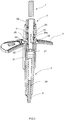
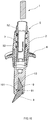
- FIGs. 1-4 show a first embodiment of the leg assembly for a pole.
- the leg assembly may be fixed on poles such as mountaineering poles or ski poles.
- the pole comprises a pole body 1.
- the leg assembly comprises a support leg 2, a snow tray 3 (or a mud tray), and a connecting sleeve 5.
- the connecting sleeve 5 has multiple elastic limiting clamps 51 at the peripheral surface of the connecting sleeve 5 corresponding to the guiding slots 22, to limit the connecting sleeve 5 with the support leg 2, and each elastic limiting clamp 51 is along with the lengthwise of the connecting sleeve 5.
- the snow tray 3 is mounted and fixed on the support leg 2.
- the connecting sleeve 5 is inserted into an upper portion of the support leg 2 in a limiting manner.
- a bottom of the pole body 1 is inserted into the connecting sleeve 5 and tightly resists against the elastic limiting clamps 51, the elastic limiting clamps 51 will be pushed outward and limited in the guiding slots 22 of the support leg 2 to limit and fix the support leg 2. So that the connecting sleeve 5 with the pole body 1 can move upward and downward relative to the support leg 2.
- the support leg 2 provided as a short rod, and can be divided into three sections, i.e., an upper portion 211, a middle portion and a lower portion 212.
- the upper portion 211 of the support leg 2 is for receiving the connecting sleeve 5 and positioned with the connecting sleeve 5, and is generally hollow.
- the lower portion 212 is a grounded section that looks like a sharp corner.
- a metal foot 6 is mounted in the lower portion.
- the middle portion of the support leg 2 has a cylindrical external threaded section 21 connected to the snow tray 3, a cylindrical internal threaded connecting column 31 is extended downward from the center of the snow tray 3 corresponding to the middle portion of the support leg 2, and, the tray is adjustably screwed on the middle portion of the support leg 2.
- the support legs of the snow tray 3 are relatively long, so the internal threaded connecting column 31 is located on the lower side of the snow tray 3, and the internal threaded section 32 of the internal threaded connecting column 31 is located near the tray.
- the upper portion 211 of the support leg 2 has an opening for receiving the connecting sleeve 5, and the connecting sleeve 5 has an inner hole for receiving the bottom of the pole body 1.
- the diameter of the bottom of the pole body 1 is gradually reduced, the downer the smaller; that is, the bottom of the pole body 1 is in a truncated conical shape; and correspondingly, the diameter of the inner hole of the connecting sleeve 5 is gradually reduced, the downer the smaller.
- the bottom of the pole body 1 can be firmly inserted and positioned inside the inner hole of the connecting sleeve 5.
- Each elastic limiting clamps 51 is disposed at the middle of the connecting sleeve 5 and arranged along the lengthwise of the support leg 2, are configured to clamp the bottom of the pole body 1.
- each elastic limiting clamp 51 has a limiting block 53 formed with a slant guiding surface at the bottom of the elastic limiting clamp 51.
- each guiding slot 22 are longitudinally arranged at the upper portion 211 of the support leg 2 and close to the middle portion.
- the upper portion 211 of the support leg 2 has a truncated cone 23 with an inner step 25a at the inner wall of the upper portion 211 of the support leg 2.
- the connecting sleeve 5 inserted inside the upper portion 211 of the support leg 2 is limited through resisting against the inner step 25a and the limiting blocks 53 blocked in the corresponding guiding slot 22, so that the connecting sleeve 5 and the support leg 2 can be appropriately connected in a telescopic manner.
- the connecting sleeve 5 has a circular increased-diameter portion 52 at the top end of the connecting sleeve 5.
- the inner diameter of the opening on the upper portion 211 of the support leg 2 is matched with the outer diameter of the circular increased-diameter portion 52. That is, the inner diameter of the through hole on the upper portion 211 of the support leg 2 is basically equal to the outer diameter of the increased-diameter portion 52 of the connecting sleeve 5.
- the support leg 2 has a neck 25 inside the upper portion 211 and at the bottom of the truncated cone 23, forming the inner step 25a, and, the inner diameter of the neck 25 is matched with the outer diameter of the connecting sleeve 5.
- a mounting clearance 100 (generally annular) is formed between the support leg 2 and the connecting sleeve 5.
- the shock absorption spring 7 is disposed outside the connecting sleeve 5, resisting against between the increased-diameter portion 52 of the connecting sleeve 5 and the inner step 25a of the support leg 2, so that the support leg 2 has a trend to pop out downward, and shock absorption is realized when being used.
- the upper portion 211 of the support leg 2 has a truncated cone 23 with an increased diameter, and the snow tray 3 is mounted on the support leg 2 through threads.
- the internal threaded section 32 of the snow tray 3 When the snow tray 3 is limited by the lower end face of the truncated-cone structure 23 (that is, when the snow tray is properly connected), the internal threaded section 32 of the snow tray 3 finally goes beyond the external threaded section 21 on the support leg 2 and is disengaged from the external threads on the support leg 2, so that the internal threaded section 23 is located above the middle external threaded section 21 of the support leg 2. In this way, the idling can be realized, and it is difficult for the snow tray 3 to reversely roll out from the support leg 2. Only when the snow tray 3 is reversely rotated due to a downward tension force, the threads can be engaged with each other and the snow tray 3 can reversely roll out due to the action of the threads.
- the snow tray 3 has a relatively large area, reinforcing ribs 34 in a substantially spoke shape are embedded in the snow tray 3, and snow outlets 33 are distributed on the snow tray 3, so that the snow component is easily inserted into snow from being damaged.
- a metal foot 6 having a positioning column is disposed on the bottom of the support leg 2, not a knife-like tip, the support leg 2 has an inserting hole 24 for receiving the positioning column of the metal foot 6 at the bottom of the support leg 2.
- the convex ring is located below the positioning column.
- the upper end of the metal foot 6 is inserted into and fixed on the bottom of the support leg 1. With the arrangement of the metal foot 6, the wear resistance is provided to the leg assembly, and the structural strength is improved.
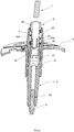
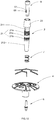
- FIGs. 5-8 show a second embodiment of the leg assembly with the shock absorption mechanism.
- the leg assembly of this embodiment differs from Embodiment 1 in that: a mud tray 4 is used.
- An internal threaded connecting column 41 corresponding to the external threaded section 21 of the support leg 2 is formed in the middle of the mud tray 4 in the leg assembly.
- the support legs of the mud tray 4 are relatively short, the internal threaded connecting column 41 is located on the upper side of the mud tray 4, and an internal threaded section 42 is formed in the internal threaded connecting column 41.
- the support legs of the snow tray 3 are relatively long, and the internal threaded connecting column 23 is located on the lower side of the snow tray 3.
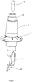
- FIGs. 9-10 show a third embodiment of the leg assembly with the shock absorption mechanism.
- the leg assembly of this embodiment differs from Embodiment 1 in that: a metal knife-like tip 8 is disposed on the bottom of the support leg 2 with the lower portion of the knife-like tip 8 exposed outside, and the knife-like tip 8 is longitudinally symmetrical.
- the support leg 2 has a positioning hole 10 for receiving the upper portion of the knife-like tip 8 at the bottom of the support leg 2; the support leg 2 has a pin-hole 101 running through the side wall of the positioning hole 10, while the knife-like tip 8 has a positioning opening 81 in the middle of the knife-like tip 8, and, a pin 9 inserts from the support leg 2 into the pin-hole 101 and the positioning opening 81 so as to fix the knife-like tip 8 with the support leg 2. In this way, when the head of the knife-like tip 8 is worn seriously, the knife-like tip 8 can be detached and then mounted again after being inverted, so that the usage life is prolonged.
- Other structures are similar to those in Embodiment 1.
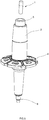
- FIGs. 11-13 show a forth embodiment of the leg assembly with the shock absorption mechanism.
- the leg assembly of this embodiment differs from Embodiment 1 in that: the middle external threaded section 21 of the support leg 2 includes two sections that may be arranged at intervals, i.e., an upper section 21a and a lower section 21b. There is a spacing section 21c between the upper section 21a and the lower section 21b.
- the support legs of the snow tray 3 are generally relatively long. Therefore, the internal threaded connecting column 31 is located on the lower side of the snow tray 3, and the internal threaded section 32 of the internal threaded connecting column 31 is located near the tray.
- the support legs of the mud tray 4 are relatively short, the internal threaded connecting column 41 is located on the upper side of the mud tray 41, but the internal threaded section 42 is still located below and near the tray.
- the internal threaded section 42 of the mud tray 4 is located between the two separated external threaded sections 21 of the support leg 2, so that the idling can be realized, as shown in FIG. 13 .
- the snow tray 3 is connected with the support leg 2
- the internal threaded section 32 of the snow tray 3 is located above the two external threaded sections 21 of the support leg 2, so that the idling can be realized, as shown in FIG. 11 .
- Other structures are similar to those in Embodiment 1.
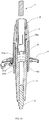
- FIGs. 14-16 show a preferred embodiment of a pole using the leg assembly of the present application
- the pole can be used as a mountaineering pole or a ski pole, and so on.
- the pole comprises a pole body 1 and the leg assembly of the present application.
- the pole boy 1 can be a conventional aluminum alloy pole or carbon fiber pole, and may be a telescopic pole.
- An inner pole is arranged in an outer pole, and locked by a locking component. These are all well-known.
- the key point is that the pole of the present application has a special shock absorption mechanism, which is disposed in the leg assembly.
- the detailed structure of the leg assembly is similar to Embodiment 1, and the leg assembly in this embodiment differs from Embodiment 1 in that: the middle portion of the support leg 2 has two separated external threaded sections 21, to facilitate threaded connection and height adjustment of the mud tray 4 or the snow tray 3, the support leg of the snow tray 3 are generally relatively long, therefore, the internal threaded connecting column 31 is extended downward from the snow tray 3, and the internal threaded section 32 is near the center of the snow tray 3. In this way, when the snow tray 3 is connected with the support leg 2, the internal threaded section 32 of the snow tray 3 is located above the two external threaded sections 21 of the support leg 2, so that the snow tray 3 can idle, as shown in FIG. 15 .
- the specific assembly process will be described below.
- the metal foot 6 or the knife-like tips 8 are positioned and fixed on the bottom of the support leg 2, the snow tray 3 or the mud tray 4 is mounted on the middle portion of the support leg 2 through threads, and the shock absorption spring 7 is mounted on the connecting sleeve 5.
- the connecting sleeve 5 is aligned with and inserted into the through hole at the upper end of the support leg 2, so that the elastic limiting clamps 51 are aligned with and positioned in the elongated slots 22.
- the elastic limiting clamps 51 When a bottom of the pole body 1 is inserted into the connecting sleeve 5 and tightly resists against the elastic limiting clamps 51, the elastic limiting clamps 51 will be pushed outward and engaged in the guiding slots 22 of the support leg 2 to limit and fix the support leg 2. Thus, the connecting sleeve 5 with the pole body 1 can move upward and downward relative to the support leg 2 through the elastic limiting clamps 51.
- the shock absorption spring 7 When in use, due to the arrangement of the shock absorption spring 7, the shock is reduced effectively, and the use comfort is improved. Moreover, no holes need to be formed on the tube of the pole body 1, so the processing steps are reduced. It is convenient to process, the manufacturing cost is reduced, and the strength of the tube is improved. The whole shock absorption mechanism is light, so the weight of the pole is reduced, and the user's comfort in use is improved. It is convenient to be assembled, and suitable for being popularized in various pole structures. The best implementation of the shock absorption mechanism for a pole has been disclosed in this embodiment. However, it should not be regarded as limiting the protection scope of the present application. All replacements using equivalent or similar technical means to realize rotation shall fall into the protection scope of the present application.
Landscapes
- Engineering & Computer Science (AREA)
- General Engineering & Computer Science (AREA)
- Health & Medical Sciences (AREA)
- Mechanical Engineering (AREA)
- Pulmonology (AREA)
- General Health & Medical Sciences (AREA)
- Physical Education & Sports Medicine (AREA)
- Walking Sticks, Umbrellas, And Fans (AREA)
- Road Signs Or Road Markings (AREA)
- Vibration Dampers (AREA)
Applications Claiming Priority (1)
| Application Number | Priority Date | Filing Date | Title |
|---|---|---|---|
| CN201911157517.0A CN110755823B (zh) | 2019-11-22 | 2019-11-22 | 一种脚托组件及其杆杖的减震机构 |
Publications (2)
| Publication Number | Publication Date |
|---|---|
| EP3824757A1 true EP3824757A1 (de) | 2021-05-26 |
| EP3824757B1 EP3824757B1 (de) | 2022-04-06 |
Family
ID=69338988
Family Applications (1)
| Application Number | Title | Priority Date | Filing Date |
|---|---|---|---|
| EP20020200.0A Active EP3824757B1 (de) | 2019-11-22 | 2020-04-28 | Beinanordnung und stossdämpfungsvorrichtung für einen stock |
Country Status (4)
| Country | Link |
|---|---|
| US (1) | US11428288B2 (de) |
| EP (1) | EP3824757B1 (de) |
| JP (1) | JP6923710B2 (de) |
| CN (1) | CN110755823B (de) |
Families Citing this family (3)
| Publication number | Priority date | Publication date | Assignee | Title |
|---|---|---|---|---|
| US11722764B2 (en) | 2018-05-07 | 2023-08-08 | Apple Inc. | Creative camera |
| CN115303110B (zh) * | 2021-12-02 | 2024-12-17 | 奥动新能源汽车科技有限公司 | 托盘安装机构、换电设备以及换电站 |
| CN119550501B (zh) * | 2025-01-22 | 2025-05-02 | 漳州沛丰新材料有限公司 | 一种混炼胶生产混炼装置及其减震装置 |
Citations (3)
| Publication number | Priority date | Publication date | Assignee | Title |
|---|---|---|---|---|
| DE4105836A1 (de) * | 1991-02-25 | 1992-09-03 | Joachim Dipl Ing Wienkoop | Kuppelbarer reibstossdaempfer mit kurzem axialhub in pendelausfuehrung, insbesondere fuer gehstockspitzen |
| CN201088205Y (zh) | 2007-10-24 | 2008-07-23 | 李明贤 | 可折叠之杖杆避震结构 |
| CN204364805U (zh) | 2015-01-29 | 2015-06-03 | 哈尔滨体育学院 | 多功能户外登山杆杖 |
Family Cites Families (18)
| Publication number | Priority date | Publication date | Assignee | Title |
|---|---|---|---|---|
| US8276943B2 (en) * | 2006-11-18 | 2012-10-02 | Black Diamond Equipment, Ltd. | Systems and methods for pole impact force damping |
| CN201033231Y (zh) * | 2007-05-29 | 2008-03-12 | 李明贤 | 一种避震装置 |
| WO2009003298A1 (de) * | 2007-07-03 | 2009-01-08 | Lekisport Ag | Stock mit stossdämpfer |
| CN101251162A (zh) * | 2008-03-28 | 2008-08-27 | 李明贤 | 杆体避震器 |
| WO2010032939A2 (ko) * | 2008-09-16 | 2010-03-25 | Kim Sang Soon | 지팡이 |
| US20130146110A1 (en) * | 2010-06-14 | 2013-06-13 | Lekisport Ag | Pole having a shock absorber |
| KR101276577B1 (ko) * | 2012-04-26 | 2013-06-18 | 김경원 | 등산용 스틱 |
| KR101366722B1 (ko) * | 2013-09-04 | 2014-02-25 | 이명아 | 높낮이 조절 장치 |
| CN203952657U (zh) * | 2014-06-24 | 2014-11-26 | 陈贤青 | 一种老人杖 |
| US9226556B1 (en) * | 2014-11-06 | 2016-01-05 | Li-Sheng Chien | Foot base for assistive device |
| CN205759487U (zh) * | 2016-05-24 | 2016-12-07 | 宁波北仑瑞柏尔宏户外用品工贸有限公司 | 一种登山杖外锁 |
| CN205757687U (zh) * | 2016-05-24 | 2016-12-07 | 宁波北仑瑞柏尔宏户外用品工贸有限公司 | 一种登山杖手柄 |
| US10575607B2 (en) * | 2017-10-10 | 2020-03-03 | Chuck Bullard | Shock absorbing walking cane |
| CN208096261U (zh) * | 2018-04-02 | 2018-11-16 | 竺祯坤 | 一种减震登山杖 |
| CN108577077B (zh) * | 2018-07-27 | 2019-09-24 | 磐安县鸿达文体用品有限公司 | 一种多功能登山杖 |
| CN209437624U (zh) * | 2018-10-12 | 2019-09-27 | 刘金鹿 | 一种具有减震和旋转定位功能的腋下拐 |
| CN110548262B (zh) * | 2019-08-21 | 2024-07-26 | 宁海兴达旅游用品有限公司 | 一种自动伸缩杆杖 |
| CN211245427U (zh) * | 2019-11-22 | 2020-08-14 | 宁海兴达旅游用品有限公司 | 一种脚托组件及其杆杖的减震机构 |
-
2019
- 2019-11-22 CN CN201911157517.0A patent/CN110755823B/zh active Active
-
2020
- 2020-04-15 US US16/848,854 patent/US11428288B2/en active Active
- 2020-04-28 EP EP20020200.0A patent/EP3824757B1/de active Active
- 2020-06-17 JP JP2020104452A patent/JP6923710B2/ja active Active
Patent Citations (3)
| Publication number | Priority date | Publication date | Assignee | Title |
|---|---|---|---|---|
| DE4105836A1 (de) * | 1991-02-25 | 1992-09-03 | Joachim Dipl Ing Wienkoop | Kuppelbarer reibstossdaempfer mit kurzem axialhub in pendelausfuehrung, insbesondere fuer gehstockspitzen |
| CN201088205Y (zh) | 2007-10-24 | 2008-07-23 | 李明贤 | 可折叠之杖杆避震结构 |
| CN204364805U (zh) | 2015-01-29 | 2015-06-03 | 哈尔滨体育学院 | 多功能户外登山杆杖 |
Also Published As
| Publication number | Publication date |
|---|---|
| JP2021079078A (ja) | 2021-05-27 |
| US20210156444A1 (en) | 2021-05-27 |
| JP6923710B2 (ja) | 2021-08-25 |
| US11428288B2 (en) | 2022-08-30 |
| CN110755823A (zh) | 2020-02-07 |
| EP3824757B1 (de) | 2022-04-06 |
| CN110755823B (zh) | 2024-08-20 |
Similar Documents
| Publication | Publication Date | Title |
|---|---|---|
| US11428288B2 (en) | Leg assembly, and shock absorption mechanism for pole | |
| CN101772363B (zh) | 具有可变长度的运动手杖的固定装置 | |
| US7628735B1 (en) | Fitness equipment having the functions of a jump rope and a dumbbell | |
| RU2564234C2 (ru) | Отсоединяемый наконечник лыжной палки и лыжная палка, снабженная этим наконечником | |
| US6082694A (en) | Golf umbrella mounting clamp | |
| US8475345B2 (en) | Exercise-cord anchored device | |
| US20250262118A1 (en) | Cane that serves as massager | |
| US6893363B1 (en) | Apparatus for practicing baseball batting | |
| US20100288319A1 (en) | Climbing crutch | |
| US6485381B1 (en) | Handle and neck for a racket | |
| CN211245427U (zh) | 一种脚托组件及其杆杖的减震机构 | |
| KR101261788B1 (ko) | 높낮이 조절 장치 | |
| US20090236867A1 (en) | Apparatus facilitating the collection of marker cones | |
| US20020088301A1 (en) | Structure of a handle and a front fork of a scooter | |
| KR102112778B1 (ko) | 낚시대 받침유닛 | |
| CN215585405U (zh) | 一种新型组合式羽毛球拍 | |
| KR200374534Y1 (ko) | 드라이버 골프채 그립 취부용 골프티 수납케이스 | |
| KR101176762B1 (ko) | 조립식 지팡이 | |
| KR102880103B1 (ko) | 등산용 스틱 | |
| KR200475502Y1 (ko) | 분리형 다단식 지팡이 | |
| CN210783194U (zh) | 一种可更换手柄的手杖连接结构 | |
| JP3150667U (ja) | 上下分離式ゴルフティー | |
| KR200254301Y1 (ko) | 목발 | |
| KR101651801B1 (ko) | 스포츠용 스틱의 고정장치 | |
| CN206914068U (zh) | 无轴式自行车轴皮 |
Legal Events
| Date | Code | Title | Description |
|---|---|---|---|
| PUAI | Public reference made under article 153(3) epc to a published international application that has entered the european phase |
Free format text: ORIGINAL CODE: 0009012 |
|
| STAA | Information on the status of an ep patent application or granted ep patent |
Free format text: STATUS: THE APPLICATION HAS BEEN PUBLISHED |
|
| STAA | Information on the status of an ep patent application or granted ep patent |
Free format text: STATUS: REQUEST FOR EXAMINATION WAS MADE |
|
| AK | Designated contracting states |
Kind code of ref document: A1 Designated state(s): AL AT BE BG CH CY CZ DE DK EE ES FI FR GB GR HR HU IE IS IT LI LT LU LV MC MK MT NL NO PL PT RO RS SE SI SK SM TR |
|
| 17P | Request for examination filed |
Effective date: 20210513 |
|
| RBV | Designated contracting states (corrected) |
Designated state(s): AL AT BE BG CH CY CZ DE DK EE ES FI FR GB GR HR HU IE IS IT LI LT LU LV MC MK MT NL NO PL PT RO RS SE SI SK SM TR |
|
| RIN1 | Information on inventor provided before grant (corrected) |
Inventor name: JINXUE, HU |
|
| GRAP | Despatch of communication of intention to grant a patent |
Free format text: ORIGINAL CODE: EPIDOSNIGR1 |
|
| STAA | Information on the status of an ep patent application or granted ep patent |
Free format text: STATUS: GRANT OF PATENT IS INTENDED |
|
| INTG | Intention to grant announced |
Effective date: 20211117 |
|
| RIN1 | Information on inventor provided before grant (corrected) |
Inventor name: HU, JINXUE |
|
| GRAS | Grant fee paid |
Free format text: ORIGINAL CODE: EPIDOSNIGR3 |
|
| GRAA | (expected) grant |
Free format text: ORIGINAL CODE: 0009210 |
|
| STAA | Information on the status of an ep patent application or granted ep patent |
Free format text: STATUS: THE PATENT HAS BEEN GRANTED |
|
| AK | Designated contracting states |
Kind code of ref document: B1 Designated state(s): AL AT BE BG CH CY CZ DE DK EE ES FI FR GB GR HR HU IE IS IT LI LT LU LV MC MK MT NL NO PL PT RO RS SE SI SK SM TR |
|
| REG | Reference to a national code |
Ref country code: GB Ref legal event code: FG4D |
|
| RIN1 | Information on inventor provided before grant (corrected) |
Inventor name: HU, JINXUE |
|
| REG | Reference to a national code |
Ref country code: CH Ref legal event code: EP |
|
| REG | Reference to a national code |
Ref country code: AT Ref legal event code: REF Ref document number: 1480475 Country of ref document: AT Kind code of ref document: T Effective date: 20220415 |
|
| REG | Reference to a national code |
Ref country code: IE Ref legal event code: FG4D |
|
| REG | Reference to a national code |
Ref country code: DE Ref legal event code: R096 Ref document number: 602020002470 Country of ref document: DE |
|
| REG | Reference to a national code |
Ref country code: LT Ref legal event code: MG9D |
|
| REG | Reference to a national code |
Ref country code: NL Ref legal event code: MP Effective date: 20220406 |
|
| REG | Reference to a national code |
Ref country code: AT Ref legal event code: MK05 Ref document number: 1480475 Country of ref document: AT Kind code of ref document: T Effective date: 20220406 |
|
| PG25 | Lapsed in a contracting state [announced via postgrant information from national office to epo] |
Ref country code: NL Free format text: LAPSE BECAUSE OF FAILURE TO SUBMIT A TRANSLATION OF THE DESCRIPTION OR TO PAY THE FEE WITHIN THE PRESCRIBED TIME-LIMIT Effective date: 20220406 |
|
| PG25 | Lapsed in a contracting state [announced via postgrant information from national office to epo] |
Ref country code: SE Free format text: LAPSE BECAUSE OF FAILURE TO SUBMIT A TRANSLATION OF THE DESCRIPTION OR TO PAY THE FEE WITHIN THE PRESCRIBED TIME-LIMIT Effective date: 20220406 Ref country code: PT Free format text: LAPSE BECAUSE OF FAILURE TO SUBMIT A TRANSLATION OF THE DESCRIPTION OR TO PAY THE FEE WITHIN THE PRESCRIBED TIME-LIMIT Effective date: 20220808 Ref country code: NO Free format text: LAPSE BECAUSE OF FAILURE TO SUBMIT A TRANSLATION OF THE DESCRIPTION OR TO PAY THE FEE WITHIN THE PRESCRIBED TIME-LIMIT Effective date: 20220706 Ref country code: LT Free format text: LAPSE BECAUSE OF FAILURE TO SUBMIT A TRANSLATION OF THE DESCRIPTION OR TO PAY THE FEE WITHIN THE PRESCRIBED TIME-LIMIT Effective date: 20220406 Ref country code: HR Free format text: LAPSE BECAUSE OF FAILURE TO SUBMIT A TRANSLATION OF THE DESCRIPTION OR TO PAY THE FEE WITHIN THE PRESCRIBED TIME-LIMIT Effective date: 20220406 Ref country code: GR Free format text: LAPSE BECAUSE OF FAILURE TO SUBMIT A TRANSLATION OF THE DESCRIPTION OR TO PAY THE FEE WITHIN THE PRESCRIBED TIME-LIMIT Effective date: 20220707 Ref country code: FI Free format text: LAPSE BECAUSE OF FAILURE TO SUBMIT A TRANSLATION OF THE DESCRIPTION OR TO PAY THE FEE WITHIN THE PRESCRIBED TIME-LIMIT Effective date: 20220406 Ref country code: ES Free format text: LAPSE BECAUSE OF FAILURE TO SUBMIT A TRANSLATION OF THE DESCRIPTION OR TO PAY THE FEE WITHIN THE PRESCRIBED TIME-LIMIT Effective date: 20220406 Ref country code: BG Free format text: LAPSE BECAUSE OF FAILURE TO SUBMIT A TRANSLATION OF THE DESCRIPTION OR TO PAY THE FEE WITHIN THE PRESCRIBED TIME-LIMIT Effective date: 20220706 Ref country code: AT Free format text: LAPSE BECAUSE OF FAILURE TO SUBMIT A TRANSLATION OF THE DESCRIPTION OR TO PAY THE FEE WITHIN THE PRESCRIBED TIME-LIMIT Effective date: 20220406 |
|
| PG25 | Lapsed in a contracting state [announced via postgrant information from national office to epo] |
Ref country code: RS Free format text: LAPSE BECAUSE OF FAILURE TO SUBMIT A TRANSLATION OF THE DESCRIPTION OR TO PAY THE FEE WITHIN THE PRESCRIBED TIME-LIMIT Effective date: 20220406 Ref country code: PL Free format text: LAPSE BECAUSE OF FAILURE TO SUBMIT A TRANSLATION OF THE DESCRIPTION OR TO PAY THE FEE WITHIN THE PRESCRIBED TIME-LIMIT Effective date: 20220406 Ref country code: LV Free format text: LAPSE BECAUSE OF FAILURE TO SUBMIT A TRANSLATION OF THE DESCRIPTION OR TO PAY THE FEE WITHIN THE PRESCRIBED TIME-LIMIT Effective date: 20220406 Ref country code: IS Free format text: LAPSE BECAUSE OF FAILURE TO SUBMIT A TRANSLATION OF THE DESCRIPTION OR TO PAY THE FEE WITHIN THE PRESCRIBED TIME-LIMIT Effective date: 20220806 |
|
| REG | Reference to a national code |
Ref country code: BE Ref legal event code: MM Effective date: 20220430 |
|
| REG | Reference to a national code |
Ref country code: DE Ref legal event code: R097 Ref document number: 602020002470 Country of ref document: DE |
|
| PG25 | Lapsed in a contracting state [announced via postgrant information from national office to epo] |
Ref country code: SM Free format text: LAPSE BECAUSE OF FAILURE TO SUBMIT A TRANSLATION OF THE DESCRIPTION OR TO PAY THE FEE WITHIN THE PRESCRIBED TIME-LIMIT Effective date: 20220406 Ref country code: SK Free format text: LAPSE BECAUSE OF FAILURE TO SUBMIT A TRANSLATION OF THE DESCRIPTION OR TO PAY THE FEE WITHIN THE PRESCRIBED TIME-LIMIT Effective date: 20220406 Ref country code: RO Free format text: LAPSE BECAUSE OF FAILURE TO SUBMIT A TRANSLATION OF THE DESCRIPTION OR TO PAY THE FEE WITHIN THE PRESCRIBED TIME-LIMIT Effective date: 20220406 Ref country code: MC Free format text: LAPSE BECAUSE OF FAILURE TO SUBMIT A TRANSLATION OF THE DESCRIPTION OR TO PAY THE FEE WITHIN THE PRESCRIBED TIME-LIMIT Effective date: 20220406 Ref country code: LU Free format text: LAPSE BECAUSE OF NON-PAYMENT OF DUE FEES Effective date: 20220428 Ref country code: EE Free format text: LAPSE BECAUSE OF FAILURE TO SUBMIT A TRANSLATION OF THE DESCRIPTION OR TO PAY THE FEE WITHIN THE PRESCRIBED TIME-LIMIT Effective date: 20220406 Ref country code: DK Free format text: LAPSE BECAUSE OF FAILURE TO SUBMIT A TRANSLATION OF THE DESCRIPTION OR TO PAY THE FEE WITHIN THE PRESCRIBED TIME-LIMIT Effective date: 20220406 Ref country code: CZ Free format text: LAPSE BECAUSE OF FAILURE TO SUBMIT A TRANSLATION OF THE DESCRIPTION OR TO PAY THE FEE WITHIN THE PRESCRIBED TIME-LIMIT Effective date: 20220406 |
|
| PLBE | No opposition filed within time limit |
Free format text: ORIGINAL CODE: 0009261 |
|
| STAA | Information on the status of an ep patent application or granted ep patent |
Free format text: STATUS: NO OPPOSITION FILED WITHIN TIME LIMIT |
|
| PG25 | Lapsed in a contracting state [announced via postgrant information from national office to epo] |
Ref country code: BE Free format text: LAPSE BECAUSE OF NON-PAYMENT OF DUE FEES Effective date: 20220430 |
|
| 26N | No opposition filed |
Effective date: 20230110 |
|
| PG25 | Lapsed in a contracting state [announced via postgrant information from national office to epo] |
Ref country code: AL Free format text: LAPSE BECAUSE OF FAILURE TO SUBMIT A TRANSLATION OF THE DESCRIPTION OR TO PAY THE FEE WITHIN THE PRESCRIBED TIME-LIMIT Effective date: 20220406 |
|
| PG25 | Lapsed in a contracting state [announced via postgrant information from national office to epo] |
Ref country code: IE Free format text: LAPSE BECAUSE OF NON-PAYMENT OF DUE FEES Effective date: 20220428 |
|
| PG25 | Lapsed in a contracting state [announced via postgrant information from national office to epo] |
Ref country code: SI Free format text: LAPSE BECAUSE OF FAILURE TO SUBMIT A TRANSLATION OF THE DESCRIPTION OR TO PAY THE FEE WITHIN THE PRESCRIBED TIME-LIMIT Effective date: 20220406 |
|
| REG | Reference to a national code |
Ref country code: CH Ref legal event code: PL |
|
| PG25 | Lapsed in a contracting state [announced via postgrant information from national office to epo] |
Ref country code: LI Free format text: LAPSE BECAUSE OF NON-PAYMENT OF DUE FEES Effective date: 20230430 Ref country code: CH Free format text: LAPSE BECAUSE OF NON-PAYMENT OF DUE FEES Effective date: 20230430 |
|
| PG25 | Lapsed in a contracting state [announced via postgrant information from national office to epo] |
Ref country code: MK Free format text: LAPSE BECAUSE OF FAILURE TO SUBMIT A TRANSLATION OF THE DESCRIPTION OR TO PAY THE FEE WITHIN THE PRESCRIBED TIME-LIMIT Effective date: 20220406 Ref country code: CY Free format text: LAPSE BECAUSE OF FAILURE TO SUBMIT A TRANSLATION OF THE DESCRIPTION OR TO PAY THE FEE WITHIN THE PRESCRIBED TIME-LIMIT Effective date: 20220406 |
|
| PG25 | Lapsed in a contracting state [announced via postgrant information from national office to epo] |
Ref country code: HU Free format text: LAPSE BECAUSE OF FAILURE TO SUBMIT A TRANSLATION OF THE DESCRIPTION OR TO PAY THE FEE WITHIN THE PRESCRIBED TIME-LIMIT; INVALID AB INITIO Effective date: 20200428 |
|
| PG25 | Lapsed in a contracting state [announced via postgrant information from national office to epo] |
Ref country code: MT Free format text: LAPSE BECAUSE OF FAILURE TO SUBMIT A TRANSLATION OF THE DESCRIPTION OR TO PAY THE FEE WITHIN THE PRESCRIBED TIME-LIMIT Effective date: 20220406 |
|
| PG25 | Lapsed in a contracting state [announced via postgrant information from national office to epo] |
Ref country code: BG Free format text: LAPSE BECAUSE OF FAILURE TO SUBMIT A TRANSLATION OF THE DESCRIPTION OR TO PAY THE FEE WITHIN THE PRESCRIBED TIME-LIMIT Effective date: 20220406 |
|
| PG25 | Lapsed in a contracting state [announced via postgrant information from national office to epo] |
Ref country code: BG Free format text: LAPSE BECAUSE OF FAILURE TO SUBMIT A TRANSLATION OF THE DESCRIPTION OR TO PAY THE FEE WITHIN THE PRESCRIBED TIME-LIMIT Effective date: 20220406 |
|
| GBPC | Gb: european patent ceased through non-payment of renewal fee |
Effective date: 20240428 |
|
| PG25 | Lapsed in a contracting state [announced via postgrant information from national office to epo] |
Ref country code: GB Free format text: LAPSE BECAUSE OF NON-PAYMENT OF DUE FEES Effective date: 20240428 |
|
| PG25 | Lapsed in a contracting state [announced via postgrant information from national office to epo] |
Ref country code: GB Free format text: LAPSE BECAUSE OF NON-PAYMENT OF DUE FEES Effective date: 20240428 |
|
| PGFP | Annual fee paid to national office [announced via postgrant information from national office to epo] |
Ref country code: DE Payment date: 20250425 Year of fee payment: 6 |
|
| PGFP | Annual fee paid to national office [announced via postgrant information from national office to epo] |
Ref country code: IT Payment date: 20250425 Year of fee payment: 6 |
|
| PGFP | Annual fee paid to national office [announced via postgrant information from national office to epo] |
Ref country code: FR Payment date: 20250425 Year of fee payment: 6 |
|
| PG25 | Lapsed in a contracting state [announced via postgrant information from national office to epo] |
Ref country code: TR Free format text: LAPSE BECAUSE OF FAILURE TO SUBMIT A TRANSLATION OF THE DESCRIPTION OR TO PAY THE FEE WITHIN THE PRESCRIBED TIME-LIMIT Effective date: 20220406 |