EP3825097A1 - Dispositif de formage des préformes en matière plastique pour obtenir des récipients en matière plastique pourvu de soupape proportionnelle - Google Patents
Dispositif de formage des préformes en matière plastique pour obtenir des récipients en matière plastique pourvu de soupape proportionnelle Download PDFInfo
- Publication number
- EP3825097A1 EP3825097A1 EP20203186.0A EP20203186A EP3825097A1 EP 3825097 A1 EP3825097 A1 EP 3825097A1 EP 20203186 A EP20203186 A EP 20203186A EP 3825097 A1 EP3825097 A1 EP 3825097A1
- Authority
- EP
- European Patent Office
- Prior art keywords
- valve
- plastic preforms
- proportional valve
- flowable medium
- plastic
- Prior art date
- Legal status (The legal status is an assumption and is not a legal conclusion. Google has not performed a legal analysis and makes no representation as to the accuracy of the status listed.)
- Granted
Links
Images



Classifications
-
- B—PERFORMING OPERATIONS; TRANSPORTING
- B29—WORKING OF PLASTICS; WORKING OF SUBSTANCES IN A PLASTIC STATE IN GENERAL
- B29C—SHAPING OR JOINING OF PLASTICS; SHAPING OF MATERIAL IN A PLASTIC STATE, NOT OTHERWISE PROVIDED FOR; AFTER-TREATMENT OF THE SHAPED PRODUCTS, e.g. REPAIRING
- B29C49/00—Blow-moulding, i.e. blowing a preform or parison to a desired shape within a mould; Apparatus therefor
- B29C49/42—Component parts, details or accessories; Auxiliary operations
- B29C49/4289—Valve constructions or configurations, e.g. arranged to reduce blowing fluid consumption
-
- B—PERFORMING OPERATIONS; TRANSPORTING
- B29—WORKING OF PLASTICS; WORKING OF SUBSTANCES IN A PLASTIC STATE IN GENERAL
- B29C—SHAPING OR JOINING OF PLASTICS; SHAPING OF MATERIAL IN A PLASTIC STATE, NOT OTHERWISE PROVIDED FOR; AFTER-TREATMENT OF THE SHAPED PRODUCTS, e.g. REPAIRING
- B29C49/00—Blow-moulding, i.e. blowing a preform or parison to a desired shape within a mould; Apparatus therefor
- B29C49/08—Biaxial stretching during blow-moulding
- B29C49/10—Biaxial stretching during blow-moulding using mechanical means for prestretching
- B29C49/122—Drive means therefor
- B29C49/123—Electric drives, e.g. linear motors
-
- B—PERFORMING OPERATIONS; TRANSPORTING
- B29—WORKING OF PLASTICS; WORKING OF SUBSTANCES IN A PLASTIC STATE IN GENERAL
- B29C—SHAPING OR JOINING OF PLASTICS; SHAPING OF MATERIAL IN A PLASTIC STATE, NOT OTHERWISE PROVIDED FOR; AFTER-TREATMENT OF THE SHAPED PRODUCTS, e.g. REPAIRING
- B29C49/00—Blow-moulding, i.e. blowing a preform or parison to a desired shape within a mould; Apparatus therefor
- B29C49/42—Component parts, details or accessories; Auxiliary operations
- B29C49/4284—Means for recycling or reusing auxiliaries or materials, e.g. blowing fluids or energy
- B29C49/42845—Recycling or reusing of fluid, e.g. pressure
- B29C49/42855—Blowing fluids, e.g. reducing fluid consumption
-
- B—PERFORMING OPERATIONS; TRANSPORTING
- B29—WORKING OF PLASTICS; WORKING OF SUBSTANCES IN A PLASTIC STATE IN GENERAL
- B29C—SHAPING OR JOINING OF PLASTICS; SHAPING OF MATERIAL IN A PLASTIC STATE, NOT OTHERWISE PROVIDED FOR; AFTER-TREATMENT OF THE SHAPED PRODUCTS, e.g. REPAIRING
- B29C49/00—Blow-moulding, i.e. blowing a preform or parison to a desired shape within a mould; Apparatus therefor
- B29C49/42—Component parts, details or accessories; Auxiliary operations
- B29C49/62—Venting means
-
- B—PERFORMING OPERATIONS; TRANSPORTING
- B29—WORKING OF PLASTICS; WORKING OF SUBSTANCES IN A PLASTIC STATE IN GENERAL
- B29C—SHAPING OR JOINING OF PLASTICS; SHAPING OF MATERIAL IN A PLASTIC STATE, NOT OTHERWISE PROVIDED FOR; AFTER-TREATMENT OF THE SHAPED PRODUCTS, e.g. REPAIRING
- B29C49/00—Blow-moulding, i.e. blowing a preform or parison to a desired shape within a mould; Apparatus therefor
- B29C49/42—Component parts, details or accessories; Auxiliary operations
- B29C49/78—Measuring, controlling or regulating
-
- B—PERFORMING OPERATIONS; TRANSPORTING
- B29—WORKING OF PLASTICS; WORKING OF SUBSTANCES IN A PLASTIC STATE IN GENERAL
- B29C—SHAPING OR JOINING OF PLASTICS; SHAPING OF MATERIAL IN A PLASTIC STATE, NOT OTHERWISE PROVIDED FOR; AFTER-TREATMENT OF THE SHAPED PRODUCTS, e.g. REPAIRING
- B29C49/00—Blow-moulding, i.e. blowing a preform or parison to a desired shape within a mould; Apparatus therefor
- B29C49/42—Component parts, details or accessories; Auxiliary operations
- B29C49/78—Measuring, controlling or regulating
- B29C49/783—Measuring, controlling or regulating blowing pressure
-
- B—PERFORMING OPERATIONS; TRANSPORTING
- B29—WORKING OF PLASTICS; WORKING OF SUBSTANCES IN A PLASTIC STATE IN GENERAL
- B29C—SHAPING OR JOINING OF PLASTICS; SHAPING OF MATERIAL IN A PLASTIC STATE, NOT OTHERWISE PROVIDED FOR; AFTER-TREATMENT OF THE SHAPED PRODUCTS, e.g. REPAIRING
- B29C49/00—Blow-moulding, i.e. blowing a preform or parison to a desired shape within a mould; Apparatus therefor
- B29C49/42—Component parts, details or accessories; Auxiliary operations
- B29C49/62—Venting means
- B29C2049/6271—Venting means for venting blowing medium, e.g. using damper or silencer
-
- B—PERFORMING OPERATIONS; TRANSPORTING
- B29—WORKING OF PLASTICS; WORKING OF SUBSTANCES IN A PLASTIC STATE IN GENERAL
- B29C—SHAPING OR JOINING OF PLASTICS; SHAPING OF MATERIAL IN A PLASTIC STATE, NOT OTHERWISE PROVIDED FOR; AFTER-TREATMENT OF THE SHAPED PRODUCTS, e.g. REPAIRING
- B29C49/00—Blow-moulding, i.e. blowing a preform or parison to a desired shape within a mould; Apparatus therefor
- B29C49/42—Component parts, details or accessories; Auxiliary operations
- B29C49/78—Measuring, controlling or regulating
- B29C49/783—Measuring, controlling or regulating blowing pressure
- B29C2049/7832—Blowing with two or more pressure levels
-
- B—PERFORMING OPERATIONS; TRANSPORTING
- B29—WORKING OF PLASTICS; WORKING OF SUBSTANCES IN A PLASTIC STATE IN GENERAL
- B29C—SHAPING OR JOINING OF PLASTICS; SHAPING OF MATERIAL IN A PLASTIC STATE, NOT OTHERWISE PROVIDED FOR; AFTER-TREATMENT OF THE SHAPED PRODUCTS, e.g. REPAIRING
- B29C49/00—Blow-moulding, i.e. blowing a preform or parison to a desired shape within a mould; Apparatus therefor
- B29C49/42—Component parts, details or accessories; Auxiliary operations
- B29C49/78—Measuring, controlling or regulating
- B29C2049/7879—Stretching, e.g. stretch rod
-
- B—PERFORMING OPERATIONS; TRANSPORTING
- B29—WORKING OF PLASTICS; WORKING OF SUBSTANCES IN A PLASTIC STATE IN GENERAL
- B29C—SHAPING OR JOINING OF PLASTICS; SHAPING OF MATERIAL IN A PLASTIC STATE, NOT OTHERWISE PROVIDED FOR; AFTER-TREATMENT OF THE SHAPED PRODUCTS, e.g. REPAIRING
- B29C2949/00—Indexing scheme relating to blow-moulding
- B29C2949/07—Preforms or parisons characterised by their configuration
- B29C2949/0715—Preforms or parisons characterised by their configuration the preform having one end closed
-
- B—PERFORMING OPERATIONS; TRANSPORTING
- B29—WORKING OF PLASTICS; WORKING OF SUBSTANCES IN A PLASTIC STATE IN GENERAL
- B29C—SHAPING OR JOINING OF PLASTICS; SHAPING OF MATERIAL IN A PLASTIC STATE, NOT OTHERWISE PROVIDED FOR; AFTER-TREATMENT OF THE SHAPED PRODUCTS, e.g. REPAIRING
- B29C49/00—Blow-moulding, i.e. blowing a preform or parison to a desired shape within a mould; Apparatus therefor
- B29C49/02—Combined blow-moulding and manufacture of the preform or the parison
- B29C49/06—Injection blow-moulding
-
- B—PERFORMING OPERATIONS; TRANSPORTING
- B29—WORKING OF PLASTICS; WORKING OF SUBSTANCES IN A PLASTIC STATE IN GENERAL
- B29C—SHAPING OR JOINING OF PLASTICS; SHAPING OF MATERIAL IN A PLASTIC STATE, NOT OTHERWISE PROVIDED FOR; AFTER-TREATMENT OF THE SHAPED PRODUCTS, e.g. REPAIRING
- B29C49/00—Blow-moulding, i.e. blowing a preform or parison to a desired shape within a mould; Apparatus therefor
- B29C49/28—Blow-moulding apparatus
- B29C49/30—Blow-moulding apparatus having movable moulds or mould parts
- B29C49/36—Blow-moulding apparatus having movable moulds or mould parts rotatable about one axis
-
- Y—GENERAL TAGGING OF NEW TECHNOLOGICAL DEVELOPMENTS; GENERAL TAGGING OF CROSS-SECTIONAL TECHNOLOGIES SPANNING OVER SEVERAL SECTIONS OF THE IPC; TECHNICAL SUBJECTS COVERED BY FORMER USPC CROSS-REFERENCE ART COLLECTIONS [XRACs] AND DIGESTS
- Y02—TECHNOLOGIES OR APPLICATIONS FOR MITIGATION OR ADAPTATION AGAINST CLIMATE CHANGE
- Y02P—CLIMATE CHANGE MITIGATION TECHNOLOGIES IN THE PRODUCTION OR PROCESSING OF GOODS
- Y02P70/00—Climate change mitigation technologies in the production process for final industrial or consumer products
- Y02P70/10—Greenhouse gas [GHG] capture, material saving, heat recovery or other energy efficient measures, e.g. motor control, characterised by manufacturing processes, e.g. for rolling metal or metal working
Definitions
- the present invention relates to a device and a method for reshaping plastic preforms into plastic containers.
- Such devices and methods have long been known from the prior art.
- heated plastic preforms are usually exposed to a flowable, in particular a gaseous, medium in order to be expanded in this way.
- a flowable, in particular a gaseous, medium in order to be expanded in this way.
- the present invention can in particular be applied to both configurations, but preferably to the use of a gaseous medium such as, in particular, (sterile) air.
- plastic preforms are first subjected to a pre-blow pressure, then an intermediate blow pressure and finally also a finish blow pressure.
- Two-way valves are usually used to switch such pressures. These can have a pre-attached air throttle. The respective times at which the valves are opened can be coupled, for example, to the movement of a so-called stretching rod, which stretches the plastic preforms in their longitudinal direction.
- the present invention is therefore based on the object of designing such devices and methods in a more versatile manner and, if necessary, of enabling interventions even during production.
- control device controls the drive device as a function of a valve position of the proportional valve and / or the valve arrangement enables the flowable medium to be recycled, this recycling of the flowable medium taking place using the proportional valve.
- the stretching rod drive is also controlled and / or regulated using data and / or values from the proportional valve, in particular data and / or values which are characteristic of an opening and / or closing state of the proportional valve are.
- the degree of stretching of the material can be further refined by this procedure. Furthermore, it would also be possible to include characteristics of the heating of the plastic preforms in the process described here, that is to say in particular also to design them as a function of the proportional valve (or a valve position of this proportional valve).
- a controllable valve is therefore proposed, i.e. in particular a valve whose flow cross section or its valve position can be set and / or controlled between two end positions, in particular a fully closed and a fully open position.
- recycling is understood to mean that the flowable medium, for example the blown air, is made available at different pressures and is returned from a higher pressure level to a reservoir with a lower pressure level. In this way, blown air, in particular blown air under pressure, can be saved.
- a valve block and in particular a high-pressure valve block in a stretch blow molding machine have a proportional valve for at least one air line, in particular for the air line P1 described below.
- This valve block can preferably recycle the air into the P1 line.
- a proportional valve is provided for switching the lowest pressure level.
- the proportional valve mentioned above can recycle the air in this line.
- said reshaping station is arranged on a carrier, in particular a movable carrier and in particular a rotatable carrier.
- a carrier in particular a movable carrier and in particular a rotatable carrier.
- This can be a so-called blower wheel.
- the drives for the rod bodies or the so-called stretching rods are motor drives and in particular electric motors.
- Linear motors are particularly preferably provided.
- these stretching rod movements are usually carried out by means of a cam control or by means of a cam-controlled drive. In this case, the movement of the individual stretching rods for the station cannot be varied.
- electric motor drives the drive of the stretching rod of each individual forming station can be controlled separately even when several forming stations are provided.
- the application device has a blow nozzle which can be placed on an opening of the plastic preform.
- the valve arrangement has a plurality of valves. These several valves can be used to switch several pressure levels. For example, a first pressure P1 can be provided, furthermore an intermediate blowing pressure Pi, furthermore a final blowing pressure P2. Another valve can be provided in order to release compressed air from the container that has already been expanded. This pressure level is referred to below as Exhaust (Ex).
- the device has a feed device in order to feed the plastic preforms to the forming station and / or a discharge device which removes the completely blown containers from the forming stations.
- a plurality of such forming stations are preferably arranged on the above-mentioned carrier.
- a control device which controls the proportional valve mentioned above.
- This control device advantageously controls and in particular regulates the proportional valve and in particular its position on the basis of a setpoint curve. This curve defines how the individual positions of the proportional valve can be approached.
- a proportional valve for the pre-blowing process (the lowest pressure P1) and a second valve for the final blowing with the pressure P2 of the container.
- a vent valve can be provided for releasing the air into the atmosphere (after the shaping process or blowing process has been carried out).
- valve arrangement has a proportional valve for the pre-blowing, as well as a second valve for the intermediate blowing and a third valve for the final blowing.
- a vent valve for releasing the air into the is also preferred Atmosphere provided.
- valve arrangement or the valve block it would also be possible for the valve arrangement or the valve block to have a proportional valve for the pre-blowing and a second proportional valve for the intermediate blowing and a third valve for the final blowing, whereby this third valve can also be designed as a conventional valve.
- a vent valve for releasing the air into the atmosphere is also preferably provided here.
- it is proposed to control and / or regulate the drive for the rod-like body or the stretching rod and the proportional valve as a function of one another.
- a control loop can particularly preferably be provided which includes the said proportional valve and the drive for the stretching stand and / or controls them as a function of one another.
- the volume flow of the pre-blowing valve and the stroke of the rod body can be coordinated with one another and predetermined target curves can also be followed during a pre-blowing process.
- control loop for heating the plastic preforms in a control loop for stretching and / or blowing.
- the present invention has the advantages that the material of the plastic preforms can be stretched better or more cheaply and can preferably also be distributed in a more defined manner. In this way, in particular, a desired weight distribution can also be achieved.
- the flowable medium in the context of the second embodiment according to the invention, it is possible for the flowable medium to be recycled, for example, into a channel with a lower pressure level also takes place via the proportional valve. This is particularly possible if the proportional valve is also used to control the first pressure stage (P1) and / or the pressure stage with the lowest pressure.
- the device has a detection device for detecting a position of the rod-like body.
- a position of the rod body in relation to the plastic preform and / or a position in the longitudinal direction of the rod body is detected.
- the detection device it is also possible for the detection device to detect a movement speed of the rod-like body, in particular a movement in its longitudinal direction.
- the detection device may detect an acceleration of the movement of the rod body.
- said proportional valve is used to recycle air in the P1 line described in more detail below.
- predetermined target curves can also be followed, in particular also during the pre-blowing.
- a rod body is understood to mean a body which extends in a preferred direction, in particular in a longitudinal direction.
- the rod body can also extend in directions perpendicular to the longitudinal direction, but significantly less than in the said preferred direction.
- the device has a first reservoir for storing the flowable medium under a first pressure and a second reservoir for storing the flowable medium under a second pressure, which in particular differs from the first pressure.
- So-called ring channels can be provided in which pre-blowing air is stored under different pressures. Starting from these reservoirs, the plastic preform can be subjected to different pressures.
- These reservoirs are preferably located on the carrier on which the forming stations are also arranged, such as in particular, but not exclusively, the blower wheel.
- this valve arrangement or the valve block has several valves. These valves are preferably assigned to different pressure levels, such as a pre-blowing pressure P1, an intermediate blowing pressure Pi and a final blowing pressure P2. These valves can preferably be switched independently of one another.
- the plastic preform is preferably initially blown, followed by intermediate blowing and finally final blowing. Finally, the plastic container can also be relieved via a further valve or the air can be released from the plastic container.
- the above-mentioned proportional valve can also act as a pure switching valve. This means that the proportional valve can also be switched between two positions, namely a closed and an open position.
- the device has a valve control device which is used to control at least one of the valve devices and in particular the proportional valve.
- This control device can preferably communicate with the control device for controlling the drive of the stretching rod.
- the proportional valve can be cleaned and, in particular, can also be cleaned with a sterilization medium such as, for example, H 2 O 2. In this way, sterile operation of the shaping device is also possible.
- the proportional valve is preferably made at least partially from materials which are insensitive to H 2 O 2 .
- the device can have a clean room, within which the plastic preforms are reshaped to form the plastic containers.
- This clean room can be separated from an (unsterile) environment by means of walls that are movable with respect to one another.
- the proportional valve has a venting function.
- a further valve element can be built into the proportional valve, such as a check valve function or a further switchable valve. This venting function can cause venting of the container to be expanded during the blowing process.
- the device has two or more proportional valves.
- the proportional valve is arranged around the rod body and / or around a blow piston. It is possible that a further process valve is arranged above or below the proportional valve. Above and below are understood to mean, in particular, an arrangement in a vertical direction or else in a longitudinal direction of the stretching rod.
- the proportional valve is preferably arranged in a row of a plurality of valves closest to the application device.
- a further process valve can be provided in addition to the proportional valve.
- the proportional valve it would also be possible for the proportional valve to be arranged next to a blow piston.
- the reshaping station can be arranged in a stationary manner or on a movable and, in particular, rotating blow wheel.
- the drive for the rod-like body or the stretching drive and the proportional valve or its drive are dependent on one another or act dependent on one another.
- the proportional valve follows a target curve.
- the desired container pressure lies in a range determined by limit points and / or limit curves.
- valve arrangement also has at least one further valve device, in particular adjacent to the proportional valve.
- the present invention is furthermore directed to a method for reshaping plastic preforms into plastic containers by means of at least one reshaping station, which reshaping station has a blow molding device within which the plastic preforms are reshaped by exposure to a flowable medium to form the plastic containers and wherein an exposure device is used to apply the plastic preforms to the flowable
- the medium is applied and has a rod body that can be inserted into the plastic preforms and the plastic preforms are stretched in their longitudinal direction at least temporarily during their forming process, this rod body being moved by means of a drive device of the stretching device and a control device controlling the drive device, and with the action of the plastic preforms with the by means of a valve arrangement flowable medium takes place, this valve arrangement the Beaufschl The plastic preforms act with at least two different pressure levels and this valve arrangement has at least one proportional valve.
- control device controls the drive device as a function of a valve position of the proportional valve and / or the valve arrangement enables the flowable medium to be recycled, this recycling of the flowable medium taking place using the proportional valve.
- the use of the proportional valve is understood to mean that a flow of the flowable medium is also routed at least temporarily via the proportional valve during recycling.
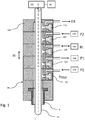
- FIG. 1 shows a schematic representation of a valve arrangement 16, hereinafter also referred to as a valve block.
- This valve block is arranged around a stretching rod 14.
- This stretching rod or this rod body is converted into a (in Fig. 1 not shown) introduced plastic preform in order to stretch it in its longitudinal direction during its expansion.
- a drive 122 (only shown schematically) is provided for this purpose, as is a control device 18 for controlling this drive.
- the reference character L identifies the longitudinal direction of the rod body and thus also its main direction of extent.
- the reference number 4 denotes an application device and in particular a blow nozzle, which can be placed against the mouth of the plastic preform.
- This loading device can also be placed against the mouth of a plastic preform in order to expand it.
- the entire valve block 16 it is possible here for the entire valve block 16 to be able to be advanced towards the plastic preform (not shown) by a movement in the stroke direction H, in order to expand it with blowing pressure.
- the valve block has a total of 5 valve devices, namely the valves 162, 164, 166, 168 and 170.
- the valve device 162 is configured as a proportional valve and the valve 164 as a recycling valve.
- the individual valves control different pressure levels.
- the reference symbol P1 denotes a pre-blow pressure
- the reference symbol Pi an intermediate blow pressure
- the reference symbol P2 a final blow pressure.
- the pressure Pi is greater than the pressure P1 and the pressure P2 is greater than the pressure Pi.
- the reference symbol EX denotes an outlet, that is to say in this case compressed air that remains after the expansion of the plastic preforms is released from this again.
- the reference numeral 160 identifies the valve housing or the housing of the valve block.
- the reference numeral 166 identifies the intermediate blow valve, the reference numeral 168 the final blow pressure valve and the reference numeral 170 the outlet valve.
- the proportional valve is arranged here directly laterally on the stretching rod or the rod body 14 and here at the height above the application device or blower nozzle 4.
- the reference numerals 144, 146 and 148 denote roughly schematically reservoirs which are used to store the compressed air under different pressures. These reservoirs can be designed, for example, as ring channels, which are preferably also located on the movable carrier on which the forming stations are also arranged.
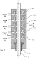
- FIG. 2 shows a further embodiment of a valve block according to the invention.
- the stretch rod drive and the control are no longer shown here.
- the reference numeral 162 here again identifies the proportional valve which is used to control the supply of the pressure stage P1. Furthermore, a valve 163 is provided here, which is used to recycle compressed air. After the blowing process has taken place, the high pressure from the now expanded bottle can be returned by means of this valve to the reservoir which holds the compressed air under pressure P1.
- the individual compressed air reservoirs which are used to hold the pressure level P1, Pi and P2, are in Figure 2 not shown.
- the proportional valve 162 is arranged directly to the side of the rod body 14 and at the height above the blower nozzle and, as noted, has an additional recycling valve 163, which, however, can be designed as a two-way valve here.
- the reference numeral 180 denotes a detection device, shown only roughly schematically, which detects a position of the proportional valve 162. In this way, using such measured values that relate to the proportional valve, the stretching rod movement can also be controlled.
- the proportional valve 162 can also have a drive that controls the proportional valve.
- FIG. 3 shows a further embodiment of a valve arrangement according to the invention or a valve block according to the invention.
- a proportional valve 162a is also provided here, as are the further valves 164a, 166a, 168a and 170a.
- the individual valves are each placed around the stretching rod 14.
- the proportional valve 162a is also arranged here directly around the stretching rod and at the level above the blow nozzle 4.
- the reference numeral 164a here serves as a recycling valve and is here above the proportional valve 162a. This means that there is recycling here can be done via the valve 164a.
- the proportional valve can also be used here, similar to in Figure 2 shown to serve as a recycling valve.
- the recycling valve 164a can be dispensed with.
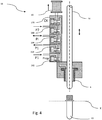
- Figure 4 shows a further embodiment of a valve arrangement according to the invention with a plastic preform 10.
- the reference symbol X denotes the transport path along which the plastic preform is transported during its forming process.
- the representation shown is the entire high-pressure valve unit or the valve block 16 laterally next to the rod body, ie the stretching rod.
- the proportional valve 162 is again arranged immediately above the blower nozzle 4, first.
- the reference numeral 30 relates to a muffler which is arranged on the outlet valve 170 (EX).
- the proportional valve can also be used here, similar to in Figure 2 shown to serve as a recycling valve.
- the recycling valve 164 can be dispensed with.
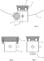
- Figure 5 shows a top view of the in Figure 4 shown arrangement.
- the proportional valve is located next to the stretching rod.
- the entire valve structure is raised or lowered completely and preferably via a linear guide 102, 104.
- Linear motors and / or pneumatic drives can also be provided in this area.
- the reference symbol TK identifies the pitch circle along which the plastic preforms are transported.
- FIG. 11 shows an embodiment to illustrate the mounting of the stretching rod arrangement and / or the valve block 100 on a carrier 108.
- FIG. 7 shows a further illustration in which a roller 106 is additionally provided. This roller 106 runs against a (not shown) guide curve and in this way the movement of the valve arrangement in the lifting direction is controlled.
- FIGS 8a and 8b show two views of a valve block according to the invention in a further embodiment.
- the different valves are distributed at different positions in the circumferential direction around the stretching rod or the rod body. In this way it is possible to shorten the flow paths for several valves.
- the proportional valve is arranged on the back of the valve block.
- Reference numeral 114 denotes a valve block holder.
- Air ducts 112 are shown in the interior of the valve block, which fluidically connect the valves to the loading device.
- FIGS 9a and 9b show a further embodiment of the valve block according to the invention.
- the valves are attached to the valve housing at an angle.
- This oblique arrangement can be seen in the illustration shown. More precisely, the individual valves are arranged in such a way that they have an optimal flow channel inside, which can for example run at an angle of 45 °.
- the directions of movement of this valve device preferably run at an angle with respect to the longitudinal direction of the rod body which is between 30 ° and 60 °, preferably between 40 ° and 50 °.
- FIG. 10 shows a further representation of a valve arrangement according to the invention.
- a silencer 30 is shown, as well as an air duct 112.
- Reference numeral 116 denotes an air duct which supplies the proportional valve 162.
- the reference numeral 163 denotes a valve device which is used for venting, in which case venting can preferably also take place via the proportional valve 162. This vent valve is arranged around the air duct 116 here.
- FIG. 11 Figure 3 shows another embodiment of the present invention.
- a proportional valve 162 and also a vent valve 163 are provided.
- an air duct 117 branches off in the direction of the proportional valve 162 and the vent valve 163.
- the reference numeral 118 denotes a valve housing.
- Fig. 12 shows an embodiment in which the proportional valve 162 and the vent valve 163 are arranged obliquely on the valve arrangement or its housing.
- a proportional valve 162 and a vent valve 163 are also provided in the embodiment shown. These are arranged in the circumferential direction of the rod body 14 at different positions and in particular opposite one another.
- Fig. 14 shows a plan view of a further embodiment of a valve device according to the invention.
- the valve devices 166 and 168 are opposite one another.
- the reference numeral 132 relates to a fastening device in order to connect a pressure supply line 134 to the valve block.
- the proportional valve 162 and the valve device 168 for switching or controlling the pressure P2 are arranged opposite one another.
- Fig. 16 shows a further embodiment in which the proportional valve 162 and the vent valve 163 are arranged laterally next to the rod body 14 and are connected to the loading device 4 via a curved air duct.
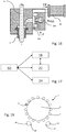
- Fig. 17 shows roughly schematically the control or regulation processes for a device according to the invention.
- a process control device 50 is preferably provided which controls the entire forming station. This in turn communicates with the control device 18, which controls the drive for the stretching rod.
- this process control device 50 can also communicate with the valve control device 22, which in turn controls the individual valves and in particular the proportional valve 162.
- the control device 18 and the valve control device can also communicate with one another.
- the process control device 50 also with the control device 24 for controlling a heating device for heating the plastic preforms.
- Fig. 18 shows a schematic representation of a device for reshaping plastic preforms 10 to form plastic containers and in particular plastic bottles 20.
- the reference numeral 32 refers to a feed device such as a transport star, which feeds plastic preforms 10 to the device.
- the reference numeral 34 relates to a further transport device which removes the manufactured or reshaped containers 20 from the device 1.
- the device 1 also has a rotatable carrier 2 on which a plurality of forming stations 6 are arranged. Each of these reshaping stations 6 has a blow molding device 8 within which the plastic preforms are reshaped.
Landscapes
- Engineering & Computer Science (AREA)
- Manufacturing & Machinery (AREA)
- Mechanical Engineering (AREA)
- Life Sciences & Earth Sciences (AREA)
- Sustainable Development (AREA)
- Blow-Moulding Or Thermoforming Of Plastics Or The Like (AREA)
Applications Claiming Priority (1)
| Application Number | Priority Date | Filing Date | Title |
|---|---|---|---|
| DE102019131188.8A DE102019131188A1 (de) | 2019-11-19 | 2019-11-19 | Vorrichtung zum Umformen von Kunststoffvorformlingen zu Kunststoffbehältnissen mit Proportionalventil |
Publications (2)
| Publication Number | Publication Date |
|---|---|
| EP3825097A1 true EP3825097A1 (fr) | 2021-05-26 |
| EP3825097B1 EP3825097B1 (fr) | 2022-09-28 |
Family
ID=73005490
Family Applications (1)
| Application Number | Title | Priority Date | Filing Date |
|---|---|---|---|
| EP20203186.0A Active EP3825097B1 (fr) | 2019-11-19 | 2020-10-21 | Dispositif de formage des préformes en matière plastique pour obtenir des récipients en matière plastique pourvu de soupape proportionnelle |
Country Status (4)
| Country | Link |
|---|---|
| US (1) | US11865762B2 (fr) |
| EP (1) | EP3825097B1 (fr) |
| CN (1) | CN214983100U (fr) |
| DE (1) | DE102019131188A1 (fr) |
Cited By (3)
| Publication number | Priority date | Publication date | Assignee | Title |
|---|---|---|---|---|
| DE102021128205A1 (de) | 2021-10-28 | 2023-05-04 | Krones Aktiengesellschaft | Vorrichtung und Verfahren zum Umformen von Kunststoffvorformlingen zu Kunststoffbehältnissen mit verstellbarer Drossel |
| EP4406724A3 (fr) * | 2023-01-25 | 2024-10-02 | Krones AG | Machine de moulage par soufflage avec soupapes aseptiques |
| EP4406725A3 (fr) * | 2023-01-25 | 2024-10-02 | Krones AG | Dispositif de transformation d'ébauches en plastique en récipients en plastique dotés d'une soupape aseptique stérilisable |
Families Citing this family (1)
| Publication number | Priority date | Publication date | Assignee | Title |
|---|---|---|---|---|
| DE102021127436A1 (de) * | 2021-10-21 | 2023-04-27 | Krones Aktiengesellschaft | Verfahren und Vorrichtung zum Blasformen von Behältnissen mit beweglichem Bodenteil |
Citations (3)
| Publication number | Priority date | Publication date | Assignee | Title |
|---|---|---|---|---|
| WO2014068080A1 (fr) * | 2012-11-01 | 2014-05-08 | Norgren Gmbh | Système de moulage par soufflage avec étirage comprenant actionnement simultané de valve de présoufflage |
| US20150042021A1 (en) * | 2012-04-26 | 2015-02-12 | Norgren Ag | Stretch blow molding system |
| DE102016013635A1 (de) * | 2016-11-16 | 2018-05-17 | Aventics Gmbh | Vorrichtung und Verfahren zur Steuerung des Blasfluiddurchflusses beim Blasformen von Behältern |
Family Cites Families (4)
| Publication number | Priority date | Publication date | Assignee | Title |
|---|---|---|---|---|
| US5169705A (en) * | 1991-02-14 | 1992-12-08 | Husky Injection Molding Systems Ltd. | Servo electric driven stretch rods for blow molding machine |
| EP2263854B1 (fr) * | 2008-12-19 | 2013-05-01 | Krones AG | Machine de formage par soufflage entraînée de manière électrique et le procédé |
| DE102010000941A1 (de) * | 2010-01-15 | 2011-07-21 | Krones Ag, 93073 | Messvorrichtung |
| DE102014115645A1 (de) * | 2014-10-28 | 2016-04-28 | Krones Ag | Verfahren und Vorrichtung zum Umformen von Kunststoffvorformlingen mit Querschnittsveränderung eines Volumenstroms |
-
2019
- 2019-11-19 DE DE102019131188.8A patent/DE102019131188A1/de active Pending
-
2020
- 2020-10-21 EP EP20203186.0A patent/EP3825097B1/fr active Active
- 2020-11-06 US US17/091,040 patent/US11865762B2/en active Active
- 2020-11-19 CN CN202022685287.XU patent/CN214983100U/zh active Active
Patent Citations (3)
| Publication number | Priority date | Publication date | Assignee | Title |
|---|---|---|---|---|
| US20150042021A1 (en) * | 2012-04-26 | 2015-02-12 | Norgren Ag | Stretch blow molding system |
| WO2014068080A1 (fr) * | 2012-11-01 | 2014-05-08 | Norgren Gmbh | Système de moulage par soufflage avec étirage comprenant actionnement simultané de valve de présoufflage |
| DE102016013635A1 (de) * | 2016-11-16 | 2018-05-17 | Aventics Gmbh | Vorrichtung und Verfahren zur Steuerung des Blasfluiddurchflusses beim Blasformen von Behältern |
Cited By (5)
| Publication number | Priority date | Publication date | Assignee | Title |
|---|---|---|---|---|
| DE102021128205A1 (de) | 2021-10-28 | 2023-05-04 | Krones Aktiengesellschaft | Vorrichtung und Verfahren zum Umformen von Kunststoffvorformlingen zu Kunststoffbehältnissen mit verstellbarer Drossel |
| EP4173797B1 (fr) | 2021-10-28 | 2024-08-21 | Krones AG | Dispositif et procédé de formage d'ébauches en plastique en récipients en plastique dotés d'un étranglement réglable |
| US12403644B2 (en) | 2021-10-28 | 2025-09-02 | Krones Ag | Apparatus and method for forming plastic preforms into plastic containers with adjustable throttle |
| EP4406724A3 (fr) * | 2023-01-25 | 2024-10-02 | Krones AG | Machine de moulage par soufflage avec soupapes aseptiques |
| EP4406725A3 (fr) * | 2023-01-25 | 2024-10-02 | Krones AG | Dispositif de transformation d'ébauches en plastique en récipients en plastique dotés d'une soupape aseptique stérilisable |
Also Published As
| Publication number | Publication date |
|---|---|
| DE102019131188A1 (de) | 2021-05-20 |
| US11865762B2 (en) | 2024-01-09 |
| CN214983100U (zh) | 2021-12-03 |
| US20210146595A1 (en) | 2021-05-20 |
| EP3825097B1 (fr) | 2022-09-28 |
Similar Documents
| Publication | Publication Date | Title |
|---|---|---|
| EP3825097B1 (fr) | Dispositif de formage des préformes en matière plastique pour obtenir des récipients en matière plastique pourvu de soupape proportionnelle | |
| WO2011023155A1 (fr) | Procédé et dispositif de moulage par soufflage de contenants | |
| DE102004045405A1 (de) | Vorrichtung zur Blasformung von Behältern | |
| EP4173797B1 (fr) | Dispositif et procédé de formage d'ébauches en plastique en récipients en plastique dotés d'un étranglement réglable | |
| DE102009020738A1 (de) | Vorrichtung zum Blasformen von Kunststoffvorformlingen mit reduziertem Totvolumen | |
| DE102013103543A1 (de) | Vorrichtung und Verfahren zum Umformen von Kunststoffvorformlingen zu Kunststoffbehältnissen | |
| DE102014115645A1 (de) | Verfahren und Vorrichtung zum Umformen von Kunststoffvorformlingen mit Querschnittsveränderung eines Volumenstroms | |
| EP2653290B1 (fr) | Machine de formage par soufflage avec refroidissement du sol dans une phase de stabilisation | |
| EP4470749A1 (fr) | Procédé et dispositif de formage d'ébauches en plastique en récipients en plastique dotés de quatre niveaux de pression et de refroidissement du fond | |
| DE102013019892B4 (de) | Hohlkörperherstellungsmaschine und Verfahren zum Umformen eines Vorformlings | |
| EP3711925B1 (fr) | Machine de moulage par soufflage pourvu de double clapet anti-retour | |
| EP1531978B1 (fr) | Procede et dispositif de regulation pneumatique | |
| EP4335616B1 (fr) | Procédé et dispositif de formage de préformes en matière plastique en récipients en matière plastique à l'aide d'une commande de pression de soufflage intermédiaire | |
| EP2803469B1 (fr) | Machine de formage par soufflage dotée d'une commande séparée de coussin de pression | |
| EP3558632B1 (fr) | Procédé et dispositif pour le moulage par soufflage de contenants à l'aide d'une partie inférieure mobile | |
| EP3558631B1 (fr) | Procédé et dispositif pour le moulage par soufflage de récipients présentant une partie de fond mobile | |
| EP4134222A1 (fr) | Machine à souffler à commande de pression lors du processus de soufflage | |
| EP4173798A1 (fr) | Procédé et dispositif de déformation d'ébauches en plastique en récipients en plastique dotés d'une évaluation de forme d'écoulement | |
| DE102022109817A1 (de) | Ventilblock | |
| EP3793804B1 (fr) | Dispositif pour mouler des ébauches en matière plastique en récipients en matière plastique et moule de soufflage et procédé pour réaliser des récipients | |
| EP3088160A1 (fr) | Procede et dispositif de transformation d'ebauches plastiques avec refroidissement de recipient | |
| DE102023115065A1 (de) | Vorrichtung und Verfahren zum Umformen von Kunststoffvorformlingen zu Kunststoffbehältnissen mit Proportionalventil | |
| DE102023117156A1 (de) | Verfahren und Vorrichtung zum Umformen von Kunststoffvorformlingen zu Kunststoffbehältnissen mit abgestimmter Reckstangenbewegung | |
| EP4442430B1 (fr) | Dispositif et procédé de fabrication de récipients à partir de préformes | |
| EP4299280B1 (fr) | Dispositif et procédé de déformation d'ébauches en plastique en récipients en plastique |
Legal Events
| Date | Code | Title | Description |
|---|---|---|---|
| PUAI | Public reference made under article 153(3) epc to a published international application that has entered the european phase |
Free format text: ORIGINAL CODE: 0009012 |
|
| STAA | Information on the status of an ep patent application or granted ep patent |
Free format text: STATUS: THE APPLICATION HAS BEEN PUBLISHED |
|
| AK | Designated contracting states |
Kind code of ref document: A1 Designated state(s): AL AT BE BG CH CY CZ DE DK EE ES FI FR GB GR HR HU IE IS IT LI LT LU LV MC MK MT NL NO PL PT RO RS SE SI SK SM TR |
|
| STAA | Information on the status of an ep patent application or granted ep patent |
Free format text: STATUS: REQUEST FOR EXAMINATION WAS MADE |
|
| 17P | Request for examination filed |
Effective date: 20211115 |
|
| RBV | Designated contracting states (corrected) |
Designated state(s): AL AT BE BG CH CY CZ DE DK EE ES FI FR GB GR HR HU IE IS IT LI LT LU LV MC MK MT NL NO PL PT RO RS SE SI SK SM TR |
|
| GRAP | Despatch of communication of intention to grant a patent |
Free format text: ORIGINAL CODE: EPIDOSNIGR1 |
|
| STAA | Information on the status of an ep patent application or granted ep patent |
Free format text: STATUS: GRANT OF PATENT IS INTENDED |
|
| RIC1 | Information provided on ipc code assigned before grant |
Ipc: B29C 49/36 20060101ALN20220428BHEP Ipc: B29C 49/12 20060101ALN20220428BHEP Ipc: B29C 49/06 20060101ALN20220428BHEP Ipc: B29C 49/78 20060101ALI20220428BHEP Ipc: B29C 49/42 20060101AFI20220428BHEP |
|
| RIC1 | Information provided on ipc code assigned before grant |
Ipc: B29C 49/36 20060101ALN20220502BHEP Ipc: B29C 49/12 20060101ALN20220502BHEP Ipc: B29C 49/06 20060101ALN20220502BHEP Ipc: B29C 49/78 20060101ALI20220502BHEP Ipc: B29C 49/42 20060101AFI20220502BHEP |
|
| INTG | Intention to grant announced |
Effective date: 20220516 |
|
| GRAS | Grant fee paid |
Free format text: ORIGINAL CODE: EPIDOSNIGR3 |
|
| GRAA | (expected) grant |
Free format text: ORIGINAL CODE: 0009210 |
|
| STAA | Information on the status of an ep patent application or granted ep patent |
Free format text: STATUS: THE PATENT HAS BEEN GRANTED |
|
| AK | Designated contracting states |
Kind code of ref document: B1 Designated state(s): AL AT BE BG CH CY CZ DE DK EE ES FI FR GB GR HR HU IE IS IT LI LT LU LV MC MK MT NL NO PL PT RO RS SE SI SK SM TR |
|
| REG | Reference to a national code |
Ref country code: GB Ref legal event code: FG4D Free format text: NOT ENGLISH |
|
| REG | Reference to a national code |
Ref country code: CH Ref legal event code: EP |
|
| REG | Reference to a national code |
Ref country code: DE Ref legal event code: R096 Ref document number: 502020001772 Country of ref document: DE |
|
| REG | Reference to a national code |
Ref country code: AT Ref legal event code: REF Ref document number: 1520973 Country of ref document: AT Kind code of ref document: T Effective date: 20221015 |
|
| REG | Reference to a national code |
Ref country code: IE Ref legal event code: FG4D Free format text: LANGUAGE OF EP DOCUMENT: GERMAN |
|
| REG | Reference to a national code |
Ref country code: LT Ref legal event code: MG9D |
|
| PG25 | Lapsed in a contracting state [announced via postgrant information from national office to epo] |
Ref country code: SE Free format text: LAPSE BECAUSE OF FAILURE TO SUBMIT A TRANSLATION OF THE DESCRIPTION OR TO PAY THE FEE WITHIN THE PRESCRIBED TIME-LIMIT Effective date: 20220928 Ref country code: RS Free format text: LAPSE BECAUSE OF FAILURE TO SUBMIT A TRANSLATION OF THE DESCRIPTION OR TO PAY THE FEE WITHIN THE PRESCRIBED TIME-LIMIT Effective date: 20220928 Ref country code: NO Free format text: LAPSE BECAUSE OF FAILURE TO SUBMIT A TRANSLATION OF THE DESCRIPTION OR TO PAY THE FEE WITHIN THE PRESCRIBED TIME-LIMIT Effective date: 20221228 Ref country code: LV Free format text: LAPSE BECAUSE OF FAILURE TO SUBMIT A TRANSLATION OF THE DESCRIPTION OR TO PAY THE FEE WITHIN THE PRESCRIBED TIME-LIMIT Effective date: 20220928 Ref country code: LT Free format text: LAPSE BECAUSE OF FAILURE TO SUBMIT A TRANSLATION OF THE DESCRIPTION OR TO PAY THE FEE WITHIN THE PRESCRIBED TIME-LIMIT Effective date: 20220928 Ref country code: FI Free format text: LAPSE BECAUSE OF FAILURE TO SUBMIT A TRANSLATION OF THE DESCRIPTION OR TO PAY THE FEE WITHIN THE PRESCRIBED TIME-LIMIT Effective date: 20220928 |
|
| REG | Reference to a national code |
Ref country code: NL Ref legal event code: MP Effective date: 20220928 |
|
| PG25 | Lapsed in a contracting state [announced via postgrant information from national office to epo] |
Ref country code: HR Free format text: LAPSE BECAUSE OF FAILURE TO SUBMIT A TRANSLATION OF THE DESCRIPTION OR TO PAY THE FEE WITHIN THE PRESCRIBED TIME-LIMIT Effective date: 20220928 Ref country code: GR Free format text: LAPSE BECAUSE OF FAILURE TO SUBMIT A TRANSLATION OF THE DESCRIPTION OR TO PAY THE FEE WITHIN THE PRESCRIBED TIME-LIMIT Effective date: 20221229 |
|
| PG25 | Lapsed in a contracting state [announced via postgrant information from national office to epo] |
Ref country code: SM Free format text: LAPSE BECAUSE OF FAILURE TO SUBMIT A TRANSLATION OF THE DESCRIPTION OR TO PAY THE FEE WITHIN THE PRESCRIBED TIME-LIMIT Effective date: 20220928 Ref country code: RO Free format text: LAPSE BECAUSE OF FAILURE TO SUBMIT A TRANSLATION OF THE DESCRIPTION OR TO PAY THE FEE WITHIN THE PRESCRIBED TIME-LIMIT Effective date: 20220928 Ref country code: PT Free format text: LAPSE BECAUSE OF FAILURE TO SUBMIT A TRANSLATION OF THE DESCRIPTION OR TO PAY THE FEE WITHIN THE PRESCRIBED TIME-LIMIT Effective date: 20230130 Ref country code: ES Free format text: LAPSE BECAUSE OF FAILURE TO SUBMIT A TRANSLATION OF THE DESCRIPTION OR TO PAY THE FEE WITHIN THE PRESCRIBED TIME-LIMIT Effective date: 20220928 Ref country code: CZ Free format text: LAPSE BECAUSE OF FAILURE TO SUBMIT A TRANSLATION OF THE DESCRIPTION OR TO PAY THE FEE WITHIN THE PRESCRIBED TIME-LIMIT Effective date: 20220928 |
|
| PG25 | Lapsed in a contracting state [announced via postgrant information from national office to epo] |
Ref country code: SK Free format text: LAPSE BECAUSE OF FAILURE TO SUBMIT A TRANSLATION OF THE DESCRIPTION OR TO PAY THE FEE WITHIN THE PRESCRIBED TIME-LIMIT Effective date: 20220928 Ref country code: PL Free format text: LAPSE BECAUSE OF FAILURE TO SUBMIT A TRANSLATION OF THE DESCRIPTION OR TO PAY THE FEE WITHIN THE PRESCRIBED TIME-LIMIT Effective date: 20220928 Ref country code: IS Free format text: LAPSE BECAUSE OF FAILURE TO SUBMIT A TRANSLATION OF THE DESCRIPTION OR TO PAY THE FEE WITHIN THE PRESCRIBED TIME-LIMIT Effective date: 20230128 Ref country code: EE Free format text: LAPSE BECAUSE OF FAILURE TO SUBMIT A TRANSLATION OF THE DESCRIPTION OR TO PAY THE FEE WITHIN THE PRESCRIBED TIME-LIMIT Effective date: 20220928 |
|
| REG | Reference to a national code |
Ref country code: BE Ref legal event code: MM Effective date: 20221031 |
|
| P01 | Opt-out of the competence of the unified patent court (upc) registered |
Effective date: 20230523 |
|
| REG | Reference to a national code |
Ref country code: DE Ref legal event code: R097 Ref document number: 502020001772 Country of ref document: DE |
|
| PG25 | Lapsed in a contracting state [announced via postgrant information from national office to epo] |
Ref country code: NL Free format text: LAPSE BECAUSE OF FAILURE TO SUBMIT A TRANSLATION OF THE DESCRIPTION OR TO PAY THE FEE WITHIN THE PRESCRIBED TIME-LIMIT Effective date: 20220928 Ref country code: MC Free format text: LAPSE BECAUSE OF FAILURE TO SUBMIT A TRANSLATION OF THE DESCRIPTION OR TO PAY THE FEE WITHIN THE PRESCRIBED TIME-LIMIT Effective date: 20220928 Ref country code: LU Free format text: LAPSE BECAUSE OF NON-PAYMENT OF DUE FEES Effective date: 20221021 Ref country code: AL Free format text: LAPSE BECAUSE OF FAILURE TO SUBMIT A TRANSLATION OF THE DESCRIPTION OR TO PAY THE FEE WITHIN THE PRESCRIBED TIME-LIMIT Effective date: 20220928 |
|
| PG25 | Lapsed in a contracting state [announced via postgrant information from national office to epo] |
Ref country code: DK Free format text: LAPSE BECAUSE OF FAILURE TO SUBMIT A TRANSLATION OF THE DESCRIPTION OR TO PAY THE FEE WITHIN THE PRESCRIBED TIME-LIMIT Effective date: 20220928 |
|
| PLBE | No opposition filed within time limit |
Free format text: ORIGINAL CODE: 0009261 |
|
| STAA | Information on the status of an ep patent application or granted ep patent |
Free format text: STATUS: NO OPPOSITION FILED WITHIN TIME LIMIT |
|
| 26N | No opposition filed |
Effective date: 20230629 |
|
| PG25 | Lapsed in a contracting state [announced via postgrant information from national office to epo] |
Ref country code: BE Free format text: LAPSE BECAUSE OF NON-PAYMENT OF DUE FEES Effective date: 20221031 |
|
| PG25 | Lapsed in a contracting state [announced via postgrant information from national office to epo] |
Ref country code: IE Free format text: LAPSE BECAUSE OF NON-PAYMENT OF DUE FEES Effective date: 20221021 |
|
| PG25 | Lapsed in a contracting state [announced via postgrant information from national office to epo] |
Ref country code: SI Free format text: LAPSE BECAUSE OF FAILURE TO SUBMIT A TRANSLATION OF THE DESCRIPTION OR TO PAY THE FEE WITHIN THE PRESCRIBED TIME-LIMIT Effective date: 20220928 |
|
| PG25 | Lapsed in a contracting state [announced via postgrant information from national office to epo] |
Ref country code: CY Free format text: LAPSE BECAUSE OF FAILURE TO SUBMIT A TRANSLATION OF THE DESCRIPTION OR TO PAY THE FEE WITHIN THE PRESCRIBED TIME-LIMIT Effective date: 20220928 |
|
| PG25 | Lapsed in a contracting state [announced via postgrant information from national office to epo] |
Ref country code: MK Free format text: LAPSE BECAUSE OF FAILURE TO SUBMIT A TRANSLATION OF THE DESCRIPTION OR TO PAY THE FEE WITHIN THE PRESCRIBED TIME-LIMIT Effective date: 20220928 |
|
| PG25 | Lapsed in a contracting state [announced via postgrant information from national office to epo] |
Ref country code: HU Free format text: LAPSE BECAUSE OF FAILURE TO SUBMIT A TRANSLATION OF THE DESCRIPTION OR TO PAY THE FEE WITHIN THE PRESCRIBED TIME-LIMIT; INVALID AB INITIO Effective date: 20201021 Ref country code: BG Free format text: LAPSE BECAUSE OF FAILURE TO SUBMIT A TRANSLATION OF THE DESCRIPTION OR TO PAY THE FEE WITHIN THE PRESCRIBED TIME-LIMIT Effective date: 20220928 |
|
| PG25 | Lapsed in a contracting state [announced via postgrant information from national office to epo] |
Ref country code: MT Free format text: LAPSE BECAUSE OF FAILURE TO SUBMIT A TRANSLATION OF THE DESCRIPTION OR TO PAY THE FEE WITHIN THE PRESCRIBED TIME-LIMIT Effective date: 20220928 |
|
| GBPC | Gb: european patent ceased through non-payment of renewal fee |
Effective date: 20241021 |
|
| PG25 | Lapsed in a contracting state [announced via postgrant information from national office to epo] |
Ref country code: GB Free format text: LAPSE BECAUSE OF NON-PAYMENT OF DUE FEES Effective date: 20241021 |
|
| PGFP | Annual fee paid to national office [announced via postgrant information from national office to epo] |
Ref country code: IT Payment date: 20250922 Year of fee payment: 6 |
|
| PGFP | Annual fee paid to national office [announced via postgrant information from national office to epo] |
Ref country code: FR Payment date: 20250908 Year of fee payment: 6 |
|
| REG | Reference to a national code |
Ref country code: CH Ref legal event code: U11 Free format text: ST27 STATUS EVENT CODE: U-0-0-U10-U11 (AS PROVIDED BY THE NATIONAL OFFICE) Effective date: 20251101 |
|
| PG25 | Lapsed in a contracting state [announced via postgrant information from national office to epo] |
Ref country code: TR Free format text: LAPSE BECAUSE OF FAILURE TO SUBMIT A TRANSLATION OF THE DESCRIPTION OR TO PAY THE FEE WITHIN THE PRESCRIBED TIME-LIMIT Effective date: 20220928 |
|
| PGFP | Annual fee paid to national office [announced via postgrant information from national office to epo] |
Ref country code: DE Payment date: 20250902 Year of fee payment: 6 |
|
| PGFP | Annual fee paid to national office [announced via postgrant information from national office to epo] |
Ref country code: AT Payment date: 20260113 Year of fee payment: 5 |
|
| PGFP | Annual fee paid to national office [announced via postgrant information from national office to epo] |
Ref country code: CH Payment date: 20251101 Year of fee payment: 6 |
|
| REG | Reference to a national code |
Ref country code: CH Ref legal event code: R17 Free format text: ST27 STATUS EVENT CODE: U-0-0-R10-R17 (AS PROVIDED BY THE NATIONAL OFFICE) Effective date: 20260410 |