EP3825103B1 - Siegelvorrichtung und verfahren zu einem wechsel einer siegeleinheit der siegelvorrichtung - Google Patents
Siegelvorrichtung und verfahren zu einem wechsel einer siegeleinheit der siegelvorrichtung Download PDFInfo
- Publication number
- EP3825103B1 EP3825103B1 EP20209206.0A EP20209206A EP3825103B1 EP 3825103 B1 EP3825103 B1 EP 3825103B1 EP 20209206 A EP20209206 A EP 20209206A EP 3825103 B1 EP3825103 B1 EP 3825103B1
- Authority
- EP
- European Patent Office
- Prior art keywords
- unit
- sealing
- heating
- elements
- sealing device
- Prior art date
- Legal status (The legal status is an assumption and is not a legal conclusion. Google has not performed a legal analysis and makes no representation as to the accuracy of the status listed.)
- Active
Links
Images


Classifications
-
- B—PERFORMING OPERATIONS; TRANSPORTING
- B29—WORKING OF PLASTICS; WORKING OF SUBSTANCES IN A PLASTIC STATE IN GENERAL
- B29C—SHAPING OR JOINING OF PLASTICS; SHAPING OF MATERIAL IN A PLASTIC STATE, NOT OTHERWISE PROVIDED FOR; AFTER-TREATMENT OF THE SHAPED PRODUCTS, e.g. REPAIRING
- B29C66/00—General aspects of processes or apparatus for joining preformed parts
- B29C66/40—General aspects of joining substantially flat articles, e.g. plates, sheets or web-like materials; Making flat seams in tubular or hollow articles; Joining single elements to substantially flat surfaces
- B29C66/41—Joining substantially flat articles ; Making flat seams in tubular or hollow articles
- B29C66/43—Joining a relatively small portion of the surface of said articles
- B29C66/431—Joining the articles to themselves
- B29C66/4312—Joining the articles to themselves for making flat seams in tubular or hollow articles, e.g. transversal seams
-
- B—PERFORMING OPERATIONS; TRANSPORTING
- B29—WORKING OF PLASTICS; WORKING OF SUBSTANCES IN A PLASTIC STATE IN GENERAL
- B29C—SHAPING OR JOINING OF PLASTICS; SHAPING OF MATERIAL IN A PLASTIC STATE, NOT OTHERWISE PROVIDED FOR; AFTER-TREATMENT OF THE SHAPED PRODUCTS, e.g. REPAIRING
- B29C65/00—Joining or sealing of preformed parts, e.g. welding of plastics materials; Apparatus therefor
- B29C65/02—Joining or sealing of preformed parts, e.g. welding of plastics materials; Apparatus therefor by heating, with or without pressure
- B29C65/18—Joining or sealing of preformed parts, e.g. welding of plastics materials; Apparatus therefor by heating, with or without pressure using heated tools
-
- B—PERFORMING OPERATIONS; TRANSPORTING
- B29—WORKING OF PLASTICS; WORKING OF SUBSTANCES IN A PLASTIC STATE IN GENERAL
- B29C—SHAPING OR JOINING OF PLASTICS; SHAPING OF MATERIAL IN A PLASTIC STATE, NOT OTHERWISE PROVIDED FOR; AFTER-TREATMENT OF THE SHAPED PRODUCTS, e.g. REPAIRING
- B29C65/00—Joining or sealing of preformed parts, e.g. welding of plastics materials; Apparatus therefor
- B29C65/02—Joining or sealing of preformed parts, e.g. welding of plastics materials; Apparatus therefor by heating, with or without pressure
- B29C65/18—Joining or sealing of preformed parts, e.g. welding of plastics materials; Apparatus therefor by heating, with or without pressure using heated tools
- B29C65/24—Joining or sealing of preformed parts, e.g. welding of plastics materials; Apparatus therefor by heating, with or without pressure using heated tools characterised by the means for heating the tool
- B29C65/30—Electrical means
- B29C65/305—Electrical means involving the use of cartridge heaters
-
- B—PERFORMING OPERATIONS; TRANSPORTING
- B29—WORKING OF PLASTICS; WORKING OF SUBSTANCES IN A PLASTIC STATE IN GENERAL
- B29C—SHAPING OR JOINING OF PLASTICS; SHAPING OF MATERIAL IN A PLASTIC STATE, NOT OTHERWISE PROVIDED FOR; AFTER-TREATMENT OF THE SHAPED PRODUCTS, e.g. REPAIRING
- B29C66/00—General aspects of processes or apparatus for joining preformed parts
- B29C66/01—General aspects dealing with the joint area or with the area to be joined
- B29C66/05—Particular design of joint configurations
- B29C66/10—Particular design of joint configurations particular design of the joint cross-sections
- B29C66/11—Joint cross-sections comprising a single joint-segment, i.e. one of the parts to be joined comprising a single joint-segment in the joint cross-section
- B29C66/112—Single lapped joints
- B29C66/1122—Single lap to lap joints, i.e. overlap joints
-
- B—PERFORMING OPERATIONS; TRANSPORTING
- B29—WORKING OF PLASTICS; WORKING OF SUBSTANCES IN A PLASTIC STATE IN GENERAL
- B29C—SHAPING OR JOINING OF PLASTICS; SHAPING OF MATERIAL IN A PLASTIC STATE, NOT OTHERWISE PROVIDED FOR; AFTER-TREATMENT OF THE SHAPED PRODUCTS, e.g. REPAIRING
- B29C66/00—General aspects of processes or apparatus for joining preformed parts
- B29C66/80—General aspects of machine operations or constructions and parts thereof
-
- B—PERFORMING OPERATIONS; TRANSPORTING
- B29—WORKING OF PLASTICS; WORKING OF SUBSTANCES IN A PLASTIC STATE IN GENERAL
- B29C—SHAPING OR JOINING OF PLASTICS; SHAPING OF MATERIAL IN A PLASTIC STATE, NOT OTHERWISE PROVIDED FOR; AFTER-TREATMENT OF THE SHAPED PRODUCTS, e.g. REPAIRING
- B29C66/00—General aspects of processes or apparatus for joining preformed parts
- B29C66/80—General aspects of machine operations or constructions and parts thereof
- B29C66/81—General aspects of the pressing elements, i.e. the elements applying pressure on the parts to be joined in the area to be joined, e.g. the welding jaws or clamps
- B29C66/814—General aspects of the pressing elements, i.e. the elements applying pressure on the parts to be joined in the area to be joined, e.g. the welding jaws or clamps characterised by the design of the pressing elements, e.g. of the welding jaws or clamps
- B29C66/8141—General aspects of the pressing elements, i.e. the elements applying pressure on the parts to be joined in the area to be joined, e.g. the welding jaws or clamps characterised by the design of the pressing elements, e.g. of the welding jaws or clamps characterised by the surface geometry of the part of the pressing elements, e.g. welding jaws or clamps, coming into contact with the parts to be joined
- B29C66/81433—General aspects of the pressing elements, i.e. the elements applying pressure on the parts to be joined in the area to be joined, e.g. the welding jaws or clamps characterised by the design of the pressing elements, e.g. of the welding jaws or clamps characterised by the surface geometry of the part of the pressing elements, e.g. welding jaws or clamps, coming into contact with the parts to be joined being toothed, i.e. comprising several teeth or pins, or being patterned
- B29C66/81435—General aspects of the pressing elements, i.e. the elements applying pressure on the parts to be joined in the area to be joined, e.g. the welding jaws or clamps characterised by the design of the pressing elements, e.g. of the welding jaws or clamps characterised by the surface geometry of the part of the pressing elements, e.g. welding jaws or clamps, coming into contact with the parts to be joined being toothed, i.e. comprising several teeth or pins, or being patterned comprising several parallel ridges, e.g. for crimping
-
- B—PERFORMING OPERATIONS; TRANSPORTING
- B29—WORKING OF PLASTICS; WORKING OF SUBSTANCES IN A PLASTIC STATE IN GENERAL
- B29C—SHAPING OR JOINING OF PLASTICS; SHAPING OF MATERIAL IN A PLASTIC STATE, NOT OTHERWISE PROVIDED FOR; AFTER-TREATMENT OF THE SHAPED PRODUCTS, e.g. REPAIRING
- B29C66/00—General aspects of processes or apparatus for joining preformed parts
- B29C66/80—General aspects of machine operations or constructions and parts thereof
- B29C66/81—General aspects of the pressing elements, i.e. the elements applying pressure on the parts to be joined in the area to be joined, e.g. the welding jaws or clamps
- B29C66/816—General aspects of the pressing elements, i.e. the elements applying pressure on the parts to be joined in the area to be joined, e.g. the welding jaws or clamps characterised by the mounting of the pressing elements, e.g. of the welding jaws or clamps
- B29C66/8167—Quick change joining tools or surfaces
-
- B—PERFORMING OPERATIONS; TRANSPORTING
- B29—WORKING OF PLASTICS; WORKING OF SUBSTANCES IN A PLASTIC STATE IN GENERAL
- B29C—SHAPING OR JOINING OF PLASTICS; SHAPING OF MATERIAL IN A PLASTIC STATE, NOT OTHERWISE PROVIDED FOR; AFTER-TREATMENT OF THE SHAPED PRODUCTS, e.g. REPAIRING
- B29C66/00—General aspects of processes or apparatus for joining preformed parts
- B29C66/80—General aspects of machine operations or constructions and parts thereof
- B29C66/83—General aspects of machine operations or constructions and parts thereof characterised by the movement of the joining or pressing tools
- B29C66/832—Reciprocating joining or pressing tools
- B29C66/8322—Joining or pressing tools reciprocating along one axis
- B29C66/83221—Joining or pressing tools reciprocating along one axis cooperating reciprocating tools, each tool reciprocating along one axis
-
- B—PERFORMING OPERATIONS; TRANSPORTING
- B29—WORKING OF PLASTICS; WORKING OF SUBSTANCES IN A PLASTIC STATE IN GENERAL
- B29C—SHAPING OR JOINING OF PLASTICS; SHAPING OF MATERIAL IN A PLASTIC STATE, NOT OTHERWISE PROVIDED FOR; AFTER-TREATMENT OF THE SHAPED PRODUCTS, e.g. REPAIRING
- B29C66/00—General aspects of processes or apparatus for joining preformed parts
- B29C66/80—General aspects of machine operations or constructions and parts thereof
- B29C66/84—Specific machine types or machines suitable for specific applications
- B29C66/849—Packaging machines
-
- B—PERFORMING OPERATIONS; TRANSPORTING
- B29—WORKING OF PLASTICS; WORKING OF SUBSTANCES IN A PLASTIC STATE IN GENERAL
- B29C—SHAPING OR JOINING OF PLASTICS; SHAPING OF MATERIAL IN A PLASTIC STATE, NOT OTHERWISE PROVIDED FOR; AFTER-TREATMENT OF THE SHAPED PRODUCTS, e.g. REPAIRING
- B29C66/00—General aspects of processes or apparatus for joining preformed parts
- B29C66/80—General aspects of machine operations or constructions and parts thereof
- B29C66/87—Auxiliary operations or devices
- B29C66/876—Maintenance or cleaning
-
- B—PERFORMING OPERATIONS; TRANSPORTING
- B29—WORKING OF PLASTICS; WORKING OF SUBSTANCES IN A PLASTIC STATE IN GENERAL
- B29C—SHAPING OR JOINING OF PLASTICS; SHAPING OF MATERIAL IN A PLASTIC STATE, NOT OTHERWISE PROVIDED FOR; AFTER-TREATMENT OF THE SHAPED PRODUCTS, e.g. REPAIRING
- B29C66/00—General aspects of processes or apparatus for joining preformed parts
- B29C66/90—Measuring or controlling the joining process
- B29C66/91—Measuring or controlling the joining process by measuring or controlling the temperature, the heat or the thermal flux
- B29C66/912—Measuring or controlling the joining process by measuring or controlling the temperature, the heat or the thermal flux by measuring the temperature, the heat or the thermal flux
- B29C66/9121—Measuring or controlling the joining process by measuring or controlling the temperature, the heat or the thermal flux by measuring the temperature, the heat or the thermal flux by measuring the temperature
- B29C66/91211—Measuring or controlling the joining process by measuring or controlling the temperature, the heat or the thermal flux by measuring the temperature, the heat or the thermal flux by measuring the temperature with special temperature measurement means or methods
- B29C66/91212—Measuring or controlling the joining process by measuring or controlling the temperature, the heat or the thermal flux by measuring the temperature, the heat or the thermal flux by measuring the temperature with special temperature measurement means or methods involving measurement means being part of the welding jaws, e.g. integrated in the welding jaws
-
- B—PERFORMING OPERATIONS; TRANSPORTING
- B29—WORKING OF PLASTICS; WORKING OF SUBSTANCES IN A PLASTIC STATE IN GENERAL
- B29C—SHAPING OR JOINING OF PLASTICS; SHAPING OF MATERIAL IN A PLASTIC STATE, NOT OTHERWISE PROVIDED FOR; AFTER-TREATMENT OF THE SHAPED PRODUCTS, e.g. REPAIRING
- B29C66/00—General aspects of processes or apparatus for joining preformed parts
- B29C66/90—Measuring or controlling the joining process
- B29C66/91—Measuring or controlling the joining process by measuring or controlling the temperature, the heat or the thermal flux
- B29C66/912—Measuring or controlling the joining process by measuring or controlling the temperature, the heat or the thermal flux by measuring the temperature, the heat or the thermal flux
- B29C66/9121—Measuring or controlling the joining process by measuring or controlling the temperature, the heat or the thermal flux by measuring the temperature, the heat or the thermal flux by measuring the temperature
- B29C66/91211—Measuring or controlling the joining process by measuring or controlling the temperature, the heat or the thermal flux by measuring the temperature, the heat or the thermal flux by measuring the temperature with special temperature measurement means or methods
- B29C66/91212—Measuring or controlling the joining process by measuring or controlling the temperature, the heat or the thermal flux by measuring the temperature, the heat or the thermal flux by measuring the temperature with special temperature measurement means or methods involving measurement means being part of the welding jaws, e.g. integrated in the welding jaws
- B29C66/91213—Measuring or controlling the joining process by measuring or controlling the temperature, the heat or the thermal flux by measuring the temperature, the heat or the thermal flux by measuring the temperature with special temperature measurement means or methods involving measurement means being part of the welding jaws, e.g. integrated in the welding jaws and measuring the electrical resistance of a resistive element belonging to said welding jaws, said element being, e.g. a thermistor
-
- B—PERFORMING OPERATIONS; TRANSPORTING
- B29—WORKING OF PLASTICS; WORKING OF SUBSTANCES IN A PLASTIC STATE IN GENERAL
- B29C—SHAPING OR JOINING OF PLASTICS; SHAPING OF MATERIAL IN A PLASTIC STATE, NOT OTHERWISE PROVIDED FOR; AFTER-TREATMENT OF THE SHAPED PRODUCTS, e.g. REPAIRING
- B29C66/00—General aspects of processes or apparatus for joining preformed parts
- B29C66/90—Measuring or controlling the joining process
- B29C66/91—Measuring or controlling the joining process by measuring or controlling the temperature, the heat or the thermal flux
- B29C66/912—Measuring or controlling the joining process by measuring or controlling the temperature, the heat or the thermal flux by measuring the temperature, the heat or the thermal flux
- B29C66/9121—Measuring or controlling the joining process by measuring or controlling the temperature, the heat or the thermal flux by measuring the temperature, the heat or the thermal flux by measuring the temperature
- B29C66/91231—Measuring or controlling the joining process by measuring or controlling the temperature, the heat or the thermal flux by measuring the temperature, the heat or the thermal flux by measuring the temperature of the joining tool
-
- B—PERFORMING OPERATIONS; TRANSPORTING
- B29—WORKING OF PLASTICS; WORKING OF SUBSTANCES IN A PLASTIC STATE IN GENERAL
- B29C—SHAPING OR JOINING OF PLASTICS; SHAPING OF MATERIAL IN A PLASTIC STATE, NOT OTHERWISE PROVIDED FOR; AFTER-TREATMENT OF THE SHAPED PRODUCTS, e.g. REPAIRING
- B29C66/00—General aspects of processes or apparatus for joining preformed parts
- B29C66/90—Measuring or controlling the joining process
- B29C66/91—Measuring or controlling the joining process by measuring or controlling the temperature, the heat or the thermal flux
- B29C66/912—Measuring or controlling the joining process by measuring or controlling the temperature, the heat or the thermal flux by measuring the temperature, the heat or the thermal flux
- B29C66/9131—Measuring or controlling the joining process by measuring or controlling the temperature, the heat or the thermal flux by measuring the temperature, the heat or the thermal flux by measuring the heat or the thermal flux, i.e. the heat flux
- B29C66/91311—Measuring or controlling the joining process by measuring or controlling the temperature, the heat or the thermal flux by measuring the temperature, the heat or the thermal flux by measuring the heat or the thermal flux, i.e. the heat flux by measuring the heat generated by Joule heating or induction heating
- B29C66/91317—Measuring or controlling the joining process by measuring or controlling the temperature, the heat or the thermal flux by measuring the temperature, the heat or the thermal flux by measuring the heat or the thermal flux, i.e. the heat flux by measuring the heat generated by Joule heating or induction heating by measuring the electrical resistance
-
- B—PERFORMING OPERATIONS; TRANSPORTING
- B29—WORKING OF PLASTICS; WORKING OF SUBSTANCES IN A PLASTIC STATE IN GENERAL
- B29C—SHAPING OR JOINING OF PLASTICS; SHAPING OF MATERIAL IN A PLASTIC STATE, NOT OTHERWISE PROVIDED FOR; AFTER-TREATMENT OF THE SHAPED PRODUCTS, e.g. REPAIRING
- B29C66/00—General aspects of processes or apparatus for joining preformed parts
- B29C66/90—Measuring or controlling the joining process
- B29C66/91—Measuring or controlling the joining process by measuring or controlling the temperature, the heat or the thermal flux
- B29C66/914—Measuring or controlling the joining process by measuring or controlling the temperature, the heat or the thermal flux by controlling or regulating the temperature, the heat or the thermal flux
- B29C66/9141—Measuring or controlling the joining process by measuring or controlling the temperature, the heat or the thermal flux by controlling or regulating the temperature, the heat or the thermal flux by controlling or regulating the temperature
- B29C66/91421—Measuring or controlling the joining process by measuring or controlling the temperature, the heat or the thermal flux by controlling or regulating the temperature, the heat or the thermal flux by controlling or regulating the temperature of the joining tools
-
- B—PERFORMING OPERATIONS; TRANSPORTING
- B65—CONVEYING; PACKING; STORING; HANDLING THIN OR FILAMENTARY MATERIAL
- B65B—MACHINES, APPARATUS OR DEVICES FOR, OR METHODS OF, PACKAGING ARTICLES OR MATERIALS; UNPACKING
- B65B51/00—Devices for, or methods of, sealing or securing package folds or closures; Devices for gathering or twisting wrappers, or necks of bags
- B65B51/10—Applying or generating heat or pressure or combinations thereof
- B65B51/26—Devices specially adapted for producing transverse or longitudinal seams in webs or tubes
- B65B51/30—Devices, e.g. jaws, for applying pressure and heat, e.g. for subdividing filled tubes
- B65B51/303—Devices, e.g. jaws, for applying pressure and heat, e.g. for subdividing filled tubes reciprocating along only one axis
-
- B—PERFORMING OPERATIONS; TRANSPORTING
- B29—WORKING OF PLASTICS; WORKING OF SUBSTANCES IN A PLASTIC STATE IN GENERAL
- B29C—SHAPING OR JOINING OF PLASTICS; SHAPING OF MATERIAL IN A PLASTIC STATE, NOT OTHERWISE PROVIDED FOR; AFTER-TREATMENT OF THE SHAPED PRODUCTS, e.g. REPAIRING
- B29C66/00—General aspects of processes or apparatus for joining preformed parts
- B29C66/40—General aspects of joining substantially flat articles, e.g. plates, sheets or web-like materials; Making flat seams in tubular or hollow articles; Joining single elements to substantially flat surfaces
- B29C66/41—Joining substantially flat articles ; Making flat seams in tubular or hollow articles
- B29C66/43—Joining a relatively small portion of the surface of said articles
- B29C66/432—Joining a relatively small portion of the surface of said articles for making tubular articles or closed loops, e.g. by joining several sheets ; for making hollow articles or hollow preforms
- B29C66/4322—Joining a relatively small portion of the surface of said articles for making tubular articles or closed loops, e.g. by joining several sheets ; for making hollow articles or hollow preforms by joining a single sheet to itself
-
- B—PERFORMING OPERATIONS; TRANSPORTING
- B29—WORKING OF PLASTICS; WORKING OF SUBSTANCES IN A PLASTIC STATE IN GENERAL
- B29C—SHAPING OR JOINING OF PLASTICS; SHAPING OF MATERIAL IN A PLASTIC STATE, NOT OTHERWISE PROVIDED FOR; AFTER-TREATMENT OF THE SHAPED PRODUCTS, e.g. REPAIRING
- B29C66/00—General aspects of processes or apparatus for joining preformed parts
- B29C66/80—General aspects of machine operations or constructions and parts thereof
- B29C66/83—General aspects of machine operations or constructions and parts thereof characterised by the movement of the joining or pressing tools
- B29C66/834—General aspects of machine operations or constructions and parts thereof characterised by the movement of the joining or pressing tools moving with the parts to be joined
- B29C66/8351—Jaws mounted on rollers, cylinders, drums, bands, belts or chains; Flying jaws
- B29C66/83541—Jaws mounted on rollers, cylinders, drums, bands, belts or chains; Flying jaws flying jaws, e.g. jaws mounted on crank mechanisms or following a hand over hand movement
- B29C66/83543—Jaws mounted on rollers, cylinders, drums, bands, belts or chains; Flying jaws flying jaws, e.g. jaws mounted on crank mechanisms or following a hand over hand movement cooperating flying jaws
-
- B—PERFORMING OPERATIONS; TRANSPORTING
- B29—WORKING OF PLASTICS; WORKING OF SUBSTANCES IN A PLASTIC STATE IN GENERAL
- B29C—SHAPING OR JOINING OF PLASTICS; SHAPING OF MATERIAL IN A PLASTIC STATE, NOT OTHERWISE PROVIDED FOR; AFTER-TREATMENT OF THE SHAPED PRODUCTS, e.g. REPAIRING
- B29C66/00—General aspects of processes or apparatus for joining preformed parts
- B29C66/90—Measuring or controlling the joining process
- B29C66/92—Measuring or controlling the joining process by measuring or controlling the pressure, the force, the mechanical power or the displacement of the joining tools
- B29C66/922—Measuring or controlling the joining process by measuring or controlling the pressure, the force, the mechanical power or the displacement of the joining tools by measuring the pressure, the force, the mechanical power or the displacement of the joining tools
- B29C66/9221—Measuring or controlling the joining process by measuring or controlling the pressure, the force, the mechanical power or the displacement of the joining tools by measuring the pressure, the force, the mechanical power or the displacement of the joining tools by measuring the pressure, the force or the mechanical power
Definitions
- a sealing device in particular a sealing jaw, with at least one, in particular exchangeable, sealing unit for creating a sealing seam, with at least one heating unit for heating the sealing unit, with at least one bearing element which is provided for movably mounting the at least one heating unit, and with at least one decoupling unit which is provided for at least partially decoupling the at least one heating unit from at least one process force and/or connecting force acting on the sealing unit has already been proposed.
- the invention is based on a sealing device, in particular a sealing jaw, with at least one, in particular exchangeable, sealing unit for creating a sealing seam, with at least one heating unit for heating the sealing unit, with at least one bearing element which is provided to movably support the at least one heating unit, and with at least one decoupling unit which is provided to at least partially decouple the at least one heating unit from at least one process force and/or connection force acting on the sealing unit.
- the at least one bearing element is provided to apply a contact force to the at least one heating unit against the sealing unit.
- a packaging machine in particular a tubular bag machine, preferably comprises the sealing device.
- the sealing device is intended to cooperate with another sealing device, in particular designed analogously to the sealing device, to create a sealing seam, in particular of a packaging film.
- the packaging machine can in particular have a plurality of sealing devices.
- the packaging machine has the sealing devices in pairs.
- the sealing device, in particular the sealing unit is preferably intended to create a sealing seam, in particular a longitudinal sealing seam and/or a transverse sealing seam, of a package, in particular to seal a packaging film.
- the sealing device, in particular the sealing unit of the sealing device can serve as a preheater.
- the sealing device in particular the sealing unit, is intended to create a sealing seam by transferring heat to and/or mechanically pressing a packaging film.
- at least two sealing devices are arranged so that they can move relative to one another, in particular can be moved, in such a way that a packaging film can be pressed together between the sealing units of the sealing devices.
- the sealing units of the sealing devices can have corresponding, in particular profiled, sealing surfaces that can be brought into engagement with one another.
- the sealing unit is preferably designed as a sealing profile.
- "Provided" is to be understood in particular as being specially programmed, specially designed and/or specially equipped. The fact that an object is provided for a specific function is to be understood in particular as meaning that the object fulfills and/or carries out this specific function in at least one application and/or operating state.
- the sealing unit is made of a thermally conductive material, in particular of a metal and/or a metal alloy, in particular for realizing a heat transfer to a packaging film.
- the heating unit is provided to heat the sealing unit.
- the heating unit in particular at least one heating element, is in contact with the sealing unit, in particular in a planar manner.
- the heating unit is preferably arranged on a side of the sealing unit facing away from the sealing surface of the sealing unit that is in contact with a packaging film during a sealing process.
- the heating unit preferably has at least one, in particular planar, heating element.
- the heating element can be designed in particular as a heating plate, as a flattened electrical resistor, as a thick-film heating element, as a pixel-by-pixel printed heating element, as a heating wire, in particular laid flat, as a Peltier element or as another heating element that appears useful to a person skilled in the art.
- the heating unit is preferably provided to heat the sealing unit to a required operating temperature depending on a type of sealing seam to be created, a type of packaging film to be sealed, a type of assembled sealing unit and/or depending on other criteria that appear useful to a person skilled in the art.
- the heating unit can comprise at least one sensor element, for example a temperature sensor element, a current sensor element, a voltage sensor element or the like, which is intended to detect an operating temperature of the at least one heating element and/or the sealing unit.
- the at least one heating element itself can serve as a sensor element.
- a control and/or regulating unit of the sealing device and/or the packaging machine is intended to evaluate signals from the at least one sensor element, in particular for monitoring a heating process, and to control and/or regulate the heating unit depending on the evaluation.
- the control and/or regulating unit of the sealing device and/or the packaging machine is intended to evaluate a change in resistance as the temperature of the at least one heating element increases.
- control and/or regulating unit is to be understood in particular as a unit with at least one control electronics unit.
- control electronics unit is to be understood in particular as a unit with a processor unit and with a memory unit as well as with an operating program stored in the memory unit.
- the sealing unit is preferably designed to be exchangeable and can in particular be replaced with another sealing unit that is at least partially different from the sealing unit.
- the sealing unit can be exchanged independently of the heating unit.
- the heating unit can preferably be used with different sealing units.
- the sealing device can be equipped with different sealing units for different applications, in particular for different sealing seams to be created.
- the different sealing units can differ in particular in a geometry, in particular in a design of the sealing surface, in a material composition, in a material density or in other parameters that appear to be useful to a person skilled in the art.
- the sealing device preferably comprises at least one clamping unit for fixing the sealing unit, in particular to a base body of the sealing device.
- the base body preferably forms the clamping unit at least partially.
- the sealing device has at least one screw unit, at least one magnet unit, at least one vacuum unit or the like for fixing the sealing unit, in particular to the base body of the sealing device.
- the at least one bearing element is arranged on the base body and/or on the clamping unit.
- the at least one bearing element is arranged on the sealing unit.
- the sealing device comprises a plurality of bearing elements.
- at least one bearing element is provided for a movable mounting of a heating element of the heating unit.
- the bearing elements are provided for the purpose of movably mounting the heating unit, in particular the heating elements, along a single direction of movement.
- the bearing elements are provided for the purpose of movably mounting the heating unit, in particular the heating elements, along a plurality of directions of movement.
- At least one direction of movement along which the bearing elements are provided for the purpose of movably mounting the heating unit, in particular the heating elements, runs at least substantially perpendicular to the sealing surface of the sealing unit and/or to a main direction of extension of the sealing unit.
- substantially perpendicular is intended in particular to define an orientation of a direction relative to a reference direction, wherein the direction and the reference direction, in particular viewed in a projection plane, enclose an angle of 90° and the angle has a maximum deviation of in particular less than 8°, advantageously less than 5° and particularly advantageously less than 2°.
- a "main extension direction" of an object is to be understood in particular as a direction which runs parallel to a longest edge of a smallest geometric cuboid which just completely encloses the object.
- the bearing elements exert a force directed in the direction of the sealing unit on the heating unit, in particular on the heating elements.
- the bearing elements are provided to mount the heating unit, in particular the heating elements, in an indirectly movable manner, and are in particular arranged free from direct contact with the heating unit, in particular with the heating elements.
- the bearing elements are provided to mount the heating unit, in particular the heating elements, in a directly movable manner, in particular to be in direct contact with the heating unit, in particular with the heating elements.
- the bearing elements can in particular be designed as spring-elastic elements, as magnetic bearing elements, as pneumatic bearing elements, as hydraulic bearing elements, as motors, in particular as linear motors, or as other bearing elements that appear appropriate to a person skilled in the art.
- the bearing elements and/or the clamping unit, in particular the base body of the sealing device preferably form/forms the decoupling unit at least partially.
- the decoupling unit is preferably provided to at least partially, preferably completely, decouple, in particular mechanically decouple, the heating unit, in particular the heating elements, from at least one process force and/or connecting force acting on the sealing unit, in particular on the sealing surface.
- a "process force" is to be understood in particular as a force generated by a sealing process, in particular acting on the sealing unit.
- the process force can be exerted on the sealing unit at least partially by another sealing device that cooperates with the sealing device to create a sealing seam.
- the process force acts at least substantially perpendicular to the sealing surface on the sealing unit.
- a “connecting force” is to be understood in particular as a force generated by fixing the sealing unit, in particular acting on the sealing unit.
- the connecting force can be exerted at least partially by the clamping unit on the sealing unit.
- the connecting force acts on the sealing unit at least substantially parallel and/or transversely to the sealing surface.
- the connecting force is redirected in particular by a geometric contour.
- “Substantially parallel” is to be understood in particular as an alignment of a direction relative to a reference direction, in particular in a plane, wherein the direction has a deviation from the reference direction in particular of less than 8°, advantageously less than 5° and particularly advantageously less than 2°.
- the decoupling unit in particular the base body of the sealing device, has at least one contact surface, preferably at least two contact surfaces and particularly preferably at least three contact surfaces, against which the sealing unit rests in an assembled state, in particular during a sealing process.
- the decoupling unit in particular the base body of the sealing device, in particular via the at least one contact surface, is provided to absorb at least part of the process force and/or connection force acting on the sealing unit and to direct it away from the heating unit, in particular from the heating elements.
- the bearing elements are provided to enable a movement of the heating unit, in particular the heating elements, to decouple from the process force and/or the connection force depending on a process force and/or connection force acting on the sealing unit.
- the inventive design of the sealing device allows a process force and/or connection force acting on a heating unit to be minimized.
- a sealing unit that can be changed independently of the heating unit can advantageously be provided.
- An efficient heat transfer to the sealing unit can advantageously be made possible independently of a sealing unit used and/or independently of a process force and/or connection force acting on the sealing unit.
- a sealing device with an advantageously fast and dynamic heating behavior can be provided.
- a sealing device can be provided which is advantageously easy to operate and low-maintenance.
- the decoupling unit comprises the at least one bearing element, which is provided to at least partially decouple the at least one heating unit from the at least one process force and/or connection force acting on the sealing unit.
- the bearing elements in particular designed as spring-elastic elements, are provided for decoupling the heating unit, in particular the heating elements, from the process force and/or connection force acting on the sealing unit, in order to yield to the process force and/or the connection force, in particular passively, in particular until the process force and/or the connection force is/are absorbed by the base body of the sealing device.
- the sealing unit can have a different position in a first operating state, in particular during a sealing process, than in a second operating state, in particular outside of a sealing process.
- the bearing elements can be provided to enable different positions of the heating unit, in particular the heating elements, depending on different positions of the sealing unit, in particular proportional to a position of the sealing unit.
- a degree of decoupling by the bearing elements, which are in particular designed as spring-elastic elements depends on an elasticity parameter, in particular on a spring constant, and/or on a spring travel of the bearing elements.
- the bearing elements, which are in particular designed as spring-elastic elements can be selected or adjusted depending on a typical process force and/or connection force acting on the sealing unit.
- the sealing device has at least one pressure sensor element, which is arranged in particular on the heating unit, on the sealing unit and/or on at least one bearing element and is intended to detect a force acting on the heating unit, in particular on the heating elements.
- the control and/or regulating unit of the sealing device and/or the packaging machine can be intended to evaluate signals from the at least one pressure sensor element and, depending on the evaluation, to control the bearing elements, which are in particular designed as motors. to control a change in position of the heating unit, in particular the heating elements.
- a force-dependent decoupling of the heating unit from the process force and/or the connection force can advantageously be enabled.
- the changeover time and wear of the heating unit can advantageously be kept to a minimum.
- the bearing elements are provided to apply a constant contact force to the heating unit, in particular the heating elements, against the sealing unit, in particular during and/or outside of a sealing process.
- the bearing elements are provided to establish a surface contact between the heating unit, in particular between the heating elements, and the sealing unit by applying a force to the heating unit, in particular the heating elements.
- the heating unit, in particular the heating elements that are in contact with the sealing unit is/are provided to transfer heat to the sealing unit at a contact surface with the sealing unit.
- a required contact force can be set by positioning the bearing elements relative to the sealing unit and to the heating unit, by selecting an elasticity parameter of the bearing elements, by selecting a number and/or type of bearing elements, by a compression distance of the bearing elements and/or by other parameters that appear to be useful to a person skilled in the art.
- a contact pressure of the bearing elements can be adjusted mechanically, electrically, by motor, magnetically, pneumatically and/or hydraulically, in particular automatically.
- the bearing elements are preferably provided to exert a contact pressure along a force direction that runs at least substantially perpendicular to the sealing surface of the sealing unit on the heating unit, in particular on the heating elements.
- the bearing elements are provided to press the heating unit, in particular the heating elements, against a contact surface of the sealing unit that runs at least substantially parallel to the sealing surface.
- the contact surface faces away from the sealing surface.
- substantially parallel is to be understood in particular as an alignment of a direction relative to a reference direction, in particular in a plane, wherein the direction has a deviation from the reference direction, in particular less than 8°, advantageously less than 5° and particularly advantageously less than 2°.
- a efficient and constant heat transfer to the sealing unit can be enabled.
- dynamic heating behavior of the sealing unit can be enabled.
- the at least one bearing element is designed as a spring-elastic element.
- a "spring-elastic element” is to be understood in particular as an element that can be deformed relative to an initial shape by forces acting on the element, wherein the element returns to the initial shape in a stress-free state, in particular independently.
- the spring-elastic element can be deformed repeatedly without the spring-elastic element being mechanically damaged or destroyed by repeated deformation.
- the bearing elements designed as spring-elastic elements are intended to exert the contact force on the heating unit, in particular on the heating elements, by a, in particular independent, return, in particular expansion, to their initial shape.
- the bearing elements designed as spring-elastic elements can be designed in particular as rubber elements, in particular as O-rings, as rubber bands, as rubber mats, as rubber bolts or the like, as springs, in particular as compression springs, for example as spiral springs, or as other spring-elastic elements that appear to be useful to a person skilled in the art.
- a structurally efficient and low-maintenance movable mounting of the heating unit, in particular of the heating elements can be made possible.
- the sealing device comprises at least one intermediate bearing element, wherein the at least one bearing element is provided for supporting the at least one heating unit movably indirectly via the at least one intermediate bearing element.
- the sealing device comprises a plurality of intermediate bearing elements, in particular a number of intermediate bearing elements corresponding to a number of heating elements of the heating unit.
- one intermediate bearing element is assigned to each heating element.
- one heating element is arranged, in particular fastened, to each intermediate bearing element.
- at least one bearing element is assigned to each intermediate bearing element.
- the intermediate bearing element is arranged, in particular supported, on the bearing element.
- the bearing element is on one side of the Intermediate bearing element is arranged which faces away from another side of the intermediate bearing element on which the heating element is arranged.
- the intermediate bearing elements are preferably provided to mechanically couple the bearing elements, in particular in terms of force transmission, to the heating elements.
- the intermediate bearing elements are preferably rigid. An efficient coupling between the bearing elements and the heating unit, in particular the heating elements, can advantageously be enabled.
- the at least one intermediate bearing element is formed at least to a large extent from a thermally insulating material.
- the intermediate bearing elements are formed at least partially from an insulating material, from a stone, from a ceramic, from a metal with low thermal conductivity, for example from an austenitic steel alloy, from a thermally stable and insulating plastic or from another thermally insulating material that appears to be useful to a person skilled in the art.
- the intermediate bearing elements are provided to limit, in particular to prevent, heat transfer from the heating unit, in particular from the heating elements, to the decoupling unit, in particular to the bearing elements.
- the intermediate bearing elements are provided to promote energy conduction, in particular heat conduction, from the heating unit, in particular from the heating elements, away from the base body, in particular to the sealing surface.
- the intermediate bearing elements have a thermal insulation capacity and/or at least a minimal extension, so that a temperature of the bearing elements is independent of an operating temperature of the heating unit, in particular the heating elements.
- heat-related wear of the heating unit, in particular of the heating elements can be kept to a minimum and a low-wear sealing device can be provided.
- the at least one intermediate bearing element is provided for electrically contacting the at least one heating unit and/or that the at least one intermediate bearing element has at least one guide for receiving at least one electrical contact element which is provided for electrically contacting the at least one heating unit.
- the intermediate storage elements and/or the electrical contact elements are provided to supply the heating unit, in particular the heating elements, with electrical energy and/or power, in particular with electrical current.
- the electrical contact elements can be designed in particular as cables, in particular as ribbon cables, as wires, as ribbons or as other electrical contact elements that appear appropriate to a person skilled in the art.
- the sealing device preferably comprises at least a number of electrical contact elements corresponding to a number of heating elements of the heating unit.
- At least one electrical contact element is assigned to each heating element.
- the at least one electrical contact element is electrically connected to the heating element, in particular soldered, to a plug connector, to a screw connector or the like, and is provided to supply the heating element with electrical energy and/or power.
- the electrical contact elements are preferably electrically connected to at least one energy supply unit of the sealing device, for example a mains connection, an accumulator, a storage capacitor or the like.
- a guide of an intermediate bearing element for receiving at least one electrical contact element can be designed in particular as a channel within the intermediate bearing element, as a groove in an outer surface of the intermediate bearing element, as at least one clamping element arranged on the intermediate bearing element or as another guide that appears to be useful to a person skilled in the art.
- the intermediate bearing elements themselves are designed as electrical contact elements and each have at least one electrical contact point, for example a soldering point, with a heating element in each case.
- the intermediate bearing elements can be contacted by electrical contact elements of the sealing device on a side on which the bearing elements are arranged in order to supply electrical energy.
- the intermediate bearing elements can advantageously fulfill an additional function and enable a space-efficient energy supply to the heating unit, in particular the heating elements.
- the at least one bearing element is designed as an O-ring.
- the The contact pressure exerted by the bearing elements on the heating unit, in particular on the heating elements can be adjusted by selecting a diameter of the O-rings, by selecting a material composition of the O-rings, by selecting a cross-sectional thickness of the O-rings, by selecting a compression of the O-rings and/or by selecting another characteristic of the O-rings that appears to be useful to a person skilled in the art.
- the bearing elements designed as O-rings are preferably arranged in such a way, in particular fastened to the base body of the sealing device, that ring center axes of the bearing elements extend at least substantially perpendicular to the sealing surface of the sealing unit and in particular at least substantially parallel to a direction of force of the contact pressure acting on the heating unit, in particular on the heating elements.
- the bearing elements designed as O-rings preferably have a circular cross-section in an operating state free of a process force and/or connection force acting on the sealing unit.
- the bearing elements designed as O-rings have a compressed shape compared to a circular cross-section in an initial shape, in particular an elliptical cross-section, in an operating state in which a process force and/or a connecting force acts on the sealing unit.
- a cost-effective and durable possibility of movable mounting of the heating unit, in particular the heating elements can be provided.
- the at least one heating unit is at least partially formed by individual heating elements arranged and/or formed in the form of plates.
- the heating elements are preferably designed as heating plates.
- the heating elements are designed as thick-film heating elements, as pixel-by-pixel printed heating elements, as Peltier elements or as other heating elements that appear to be useful to a person skilled in the art.
- the heating unit has at least two rows of heating elements spaced apart from one another at least substantially perpendicular to the main direction of extension of the sealing unit and at least substantially parallel to the sealing surface of the sealing unit, which rows extend in particular at least substantially parallel to the main direction of extension of the sealing unit.
- the heating unit has a single row of heating elements that extend at least substantially parallel to the Main extension direction of the sealing unit.
- the heating elements are arranged equidistant from one another within a row along the main extension direction of the sealing unit.
- uniform heating of the sealing unit can be enabled.
- precise sealing seams can be created.
- the at least one heating unit in particular at least one heating element of the heating unit, has at least one, in particular specific, contour.
- the heating elements can have the contour on a side in contact with the sealing unit, in particular with the contact surface of the sealing unit.
- the contour can be etched, lasered, punched, milled, bent, pressed or introduced into the heating elements, in particular designed as heating plates, in another processing method that appears to be useful to a person skilled in the art.
- the heating elements in particular designed as pixel-by-pixel printed heating elements, can have a contour.
- the contour of the heating elements is designed to correspond to a contour of the contact surface of the sealing unit, in particular intended to interact with the contour of the contact surface of the sealing unit.
- the bearing elements are intended to apply a pressing force to the heating elements against the sealing unit in such a way that the contour of the heating elements engages with the contour of the contact surface of the sealing unit.
- different contact forces can be set depending on the different contours of the heating elements. This can advantageously enable particularly efficient and uniform heat transfer from the heating elements to the sealing unit.
- the sealing device comprises at least one, in particular dovetail-like, clamping unit, in particular the aforementioned clamping unit, which is intended to fix the at least one sealing unit and to at least partially absorb the at least one process force acting on the sealing unit.
- the clamping unit comprises in particular the, in particular fixed, base body of the sealing device and at least one clamping element, in particular movably mounted relative to the base body.
- the clamping unit can comprise a plurality of clamping elements which are arranged at a distance from one another, in particular at least substantially parallel to the main direction of extension of the sealing unit.
- the base body in particular a clamping extension of the base body, and the at least one clamping element form a fastening groove in which the sealing unit can be clamped.
- the at least one clamping element is movably mounted on the base body at least substantially perpendicular to the main direction of extension of the sealing unit and in particular at least substantially parallel to the sealing surface of the sealing unit.
- the clamping unit comprises at least one clamping actuating element operatively connected to the at least one clamping element.
- the at least one clamping element is movable, in particular displaceable, depending on an actuation of the at least one clamping actuating element.
- the at least one clamping actuating element can be designed in particular as a clamping screw, as an eccentric, in particular a conical one, as a linear motor or as another clamping actuating element that appears appropriate to a person skilled in the art.
- the sealing unit can be clamped between the at least one clamping element and the clamping extension of the base body by a movement of the at least one clamping element in the direction of the clamping extension of the base body.
- the sealing unit is fixed in a clamped state, in particular in a dovetail manner, between the at least one clamping element and the clamping extension of the base body.
- the sealing unit at least essentially forms a bung of a dovetail connection with the clamping unit, wherein in particular the at least one clamping element and the clamping extension of the base body rest on inclined surfaces of the sealing unit.
- the sealing unit can be released by a movement of the at least one clamping element away from the clamping extension of the base body, in particular to change the sealing unit.
- the clamping unit in particular the base body, is provided to at least partially absorb the process force and clamping forces acting on the sealing unit at least on the at least one contact surface of the base body.
- the sealing unit can be connected directly to the base body, in particular can be screwed on. This can advantageously enable secure fixing of the sealing unit and user-friendly changing of the sealing unit.
- the invention is based on a packaging machine, in particular a tubular bag machine, with at least one sealing device according to the invention.
- the packaging machine is preferably designed as a vertical tubular bag machine.
- the packaging machine is designed as a horizontal tubular bag machine.
- the sealing device at least partially forms a transverse heating and/or a preheating of a horizontal tubular bag machine.
- the packaging machine comprises at least two sealing devices, in particular at least one pair of sealing devices.
- the packaging machine can have further components known to a person skilled in the art, for example a transport unit for transporting a packaging film to be sealed, a feed unit for feeding products to be packaged, a sorting unit for sorting finished packaging or the like.
- a packaging machine that is advantageously user-friendly and low-maintenance can be provided.
- the invention is based on a method for changing at least one sealing unit of at least one sealing device according to the invention, wherein at least one heating unit of the sealing device remains free from change.
- the at least one clamping element is moved away from the clamping extension of the base body and in particular the sealing unit is removed from the clamping unit.
- another sealing unit can be inserted into the clamping unit and clamped by moving the at least one clamping element in the direction of the clamping extension of the base body.
- the heating unit, in particular the heating elements are automatically brought into contact with the other sealing unit by the bearing elements.
- a method can be provided that enables a time-efficient and user-friendly change of a sealing unit.
- sealing device according to the invention, the packaging machine according to the invention and/or the method according to the invention should not be limited to the application and embodiment described above.
- the sealing device according to the invention, the packaging machine according to the invention and/or the method according to the invention can have a number of individual elements, components and units as well as method steps that differs from the number stated herein in order to fulfill a function described herein.
- values within the stated limits should also be considered disclosed and can be used as desired.
- Figure 1 shows a part of a packaging machine 42a, in particular a tubular bag machine, with at least one sealing device 10a, 10a' in a schematic representation.
- the packaging machine 42a is preferably designed as a vertical tubular bag machine.
- the packaging machine 42a is designed as a horizontal tubular bag machine.
- the at least one sealing device 10a at least partially forms a transverse heating and/or a preheating of a horizontal tubular bag machine.
- the packaging machine 42a comprises at least two sealing devices 10a, 10a', in particular at least one pair of sealing devices 10a, 10a'.
- a sealing device 10a and a further sealing device 10a' are shown, which together form a pair of sealing devices 10a, 10a'.
- the packaging machine 42a can have further components known to a person skilled in the art, for example a transport unit for transporting a packaging film to be sealed, a feed unit for feeding products to be packaged, a sorting unit for sorting finished packages or the like (not shown here).
- the sealing device 10a is intended to cooperate with the further sealing device 10a', which is designed in particular analogously to the sealing device 10a, to create a sealing seam, in particular of a packaging film.
- the packaging machine 42a preferably has the sealing devices 10a, 10a' in pairs.
- the sealing devices 10a, 10a', in particular sealing units 12a of the sealing devices 10a, 10a', are preferably intended to create a sealing seam, in particular a longitudinal sealing seam and/or a transverse sealing seam, of a package, in particular to seal a packaging film.
- the sealing devices 10a, 10a', in particular the sealing units 12a of the sealing devices 10a, 10a' can serve as preheaters.
- the sealing devices 10a, 10a' are provided to form a sealing seam by heat transfer to a and/or a mechanical Pressing a packaging film.
- at least two sealing devices in the present embodiment, for example, the sealing device 10a and the further sealing device 10a', are arranged so as to be movable relative to one another, in particular displaceable, such that a packaging film can be pressed together between the sealing units 12a of the sealing devices 10a, 10a'.
- the sealing units 12a of the sealing devices 10a, 10a' can have mutually corresponding, in particular profiled, sealing surfaces 44a that can be brought into engagement with one another.
- the sealing units 12a are preferably designed as sealing profiles.
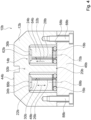
- Figure 2 shows a sectional view along the Figure 1 marked line AA of a part of the sealing device 10a of the packaging machine 42a Figure 1 in a schematic representation.
- the following descriptions and Figures 2 and 3 are limited to the sealing device 10a.
- the descriptions and the Figures 2 and 3 apply analogously to the further sealing device 10a' of the packaging machine 42a, since the further sealing device 10a' is designed analogously to the sealing device 10a.
- the sealing device 10a in particular the sealing jaw, comprises at least one, in particular exchangeable, sealing unit, in particular the aforementioned sealing unit 12a, for creating a sealing seam, at least one heating unit 14a for heating the sealing unit 12a and at least one bearing element 16a, 18a, which is provided for movably mounting the at least one heating unit 14a.
- the sealing device 10a comprises at least one decoupling unit 20a, which is provided for at least partially decoupling the at least one heating unit 14a from at least one process force and/or connection force acting on the sealing unit 12a.
- the sealing unit 12a is made of a thermally conductive material, in particular of a metal and/or a metal alloy, in particular for realizing a heat transfer to a packaging film.
- the heating unit 14a is preferably provided to heat the sealing unit 12a.
- the heating unit 14a in particular at least one heating element 34a, 36a, is in contact, in particular over a surface, with the sealing unit 12a.
- the heating unit 14a is preferably arranged on one of the surfaces used during a sealing process.
- the heating unit 14a is arranged on the side of the sealing unit 12a facing away from the sealing surface 44a of the sealing unit 12a which is in contact with a packaging film.
- the heating unit 14a preferably has at least one, in particular flat, heating element 34a, 36a.
- the heating unit 14a has, for example, a plurality of heating elements 34a, 36a, of which in Figure 2 a heating element 34a and a further heating element 36a are shown.
- the heating elements 34a, 36a can be designed in particular as heating plates, as exemplified in the present embodiment, as flattened electrical resistors, as thick-film heating elements, as pixel-by-pixel printed heating elements, as heating wires, in particular laid flat, as Peltier elements or as other heating elements that appear useful to a person skilled in the art.
- the heating unit 14a is preferably provided to heat the sealing unit 12a to a required operating temperature depending on a type of sealing seam to be created, a type of packaging film to be sealed, a type of mounted sealing unit 12a and/or depending on other criteria that appear useful to a person skilled in the art.
- the heating unit 14a can preferably comprise at least one sensor element, for example a temperature sensor element, a current sensor element, a voltage sensor element or the like, which is intended to detect an operating temperature of the heating elements 34a, 36a and/or the sealing unit 12a (not shown in more detail here).
- the heating elements 34a, 36a themselves can also serve as sensor elements.
- a control and/or regulating unit of the sealing device 10a and/or the packaging machine 42a is provided to evaluate signals from the at least one sensor element, in particular for monitoring a heating process, and to control and/or regulate the heating unit 14a depending on the evaluation (not shown here).
- the control and/or regulating unit of the sealing device 10a and/or the packaging machine 42a is provided to evaluate a change in resistance as the temperature of the heating elements 34a, 36a increases.
- the sealing unit 12a is designed to be exchangeable, in particular it can be exchanged for another sealing unit that is at least partially designed differently from the sealing unit 12a (not shown here).
- the sealing unit 12a is independent of the heating unit 14a can be exchanged.
- the heating unit 14a can preferably be used with different sealing units 12a.
- the sealing device 10a can be equipped with different sealing units 12a for different applications, in particular for different sealing seams to be created.
- the different sealing units 12a can differ in particular in a geometry, in particular in a design of the sealing surface 44a, in a material composition, in a material density or in other parameters that appear to be useful to a person skilled in the art.
- the sealing device 10a preferably comprises at least one clamping unit 40a for fixing the sealing unit 12a, in particular to a base body 46a of the sealing device 10a.
- the base body 46a preferably forms the clamping unit 40a at least partially.
- the sealing device 10a has at least one screw unit, at least one magnet unit, at least one vacuum unit or the like for fixing the sealing unit 12a, in particular to the base body 46a of the sealing device 10a.
- the at least one bearing element 16a, 18a is arranged on the base body 46a and/or on the clamping unit 40a. Alternatively, it is conceivable that the at least one bearing element 16a, 18a is arranged on the sealing unit 12a.
- the sealing device 10a comprises a plurality of bearing elements 16a, 18a.
- Two bearing elements 16a, 18a, in particular one bearing element 16a and another bearing element 18a, are shown by way of example.
- at least one bearing element 16a, 18a is provided for the movable mounting of a heating element 34a, 36a of the heating unit 14a.
- the bearing element 16a is provided for the movable mounting of a heating element 34a of the heating unit 14a and the other bearing element 18a is provided for the movable mounting of a further heating element 36a of the heating unit 14a.
- the bearing elements 16a, 18a are preferably provided for the movable mounting of the heating unit 14a, in particular the heating elements 34a, 36a, along a single direction of movement 48a.
- the bearing elements 16a, 18a are provided to movably support the heating unit 14a, in particular the heating elements 34a, 36a, along a plurality of movement directions 48a.
- At least one movement direction 48a runs along the bearing elements 16a, 18a are provided to movably support the heating unit 14a, in particular the heating elements 34a, 36a, at least substantially perpendicular to the sealing surface 44a of the sealing unit 12a and/or to a main extension direction 50a of the sealing unit 12a.
- the bearing elements 16a, 18a exert a force directed in the direction of the sealing unit 12a on the heating unit 14a, in particular on the heating elements 34a, 36a.
- the bearing elements 16a, 18a are provided to mount the heating unit 14a, in particular the heating elements 34a, 36a, in an indirectly movable manner, and are in particular arranged free from direct contact with the heating unit 14a, in particular with the heating elements 34a, 36a.
- the bearing elements 16a, 18a are provided to mount the heating unit 14a, in particular the heating elements 34a, 36a, in a directly movable manner, in particular to be in direct contact with the heating unit 14a, in particular with the heating elements 34a, 36a.
- the bearing elements 16a, 18a can be designed in particular as spring-elastic elements, as for example in the present embodiment, as magnetic bearing elements, as pneumatic bearing elements, as hydraulic bearing elements, as motors, in particular as linear motors, or as other bearing elements that appear to be useful to a person skilled in the art.
- the decoupling unit 20a is preferably provided to at least partially, preferably completely, decouple, in particular mechanically decouple, the heating unit 14a, in particular the heating elements 34a, 36a, from at least one process force and/or connecting force acting on the sealing unit 12a, in particular on the sealing surface 44a.
- the process force acts on the sealing unit 12a at least substantially perpendicular to the sealing surface 44a.
- the process force, in particular a direction of action of the process force is in Figure 2 in particular by means of first arrows 52a.
- the connecting force can be exerted at least partially by the clamping unit 40a on the sealing unit 12a.
- the connecting force acts at least substantially parallel and/or transversely to the sealing surface 44a onto the sealing unit 12a.
- the connecting force is redirected in particular by a geometric contour.
- the connecting force, in particular the effective directions of the connecting force, is/are in Figure 2 in particular by means of second arrows 54a. Individual components of the connection force are shown in Figure 2 represented by third arrows 56a.
- the decoupling unit 20a in particular the base body 46a of the sealing device 10a, has at least one contact surface 58a, preferably at least two contact surfaces 58a and particularly preferably at least three contact surfaces 58a, as exemplified in the present embodiment, against which the sealing unit 12a rests in an assembled state, in particular during a sealing process.
- the decoupling unit 20a in particular the base body 46a of the sealing device 10a, in particular via the contact surfaces 58a, is provided to absorb at least a portion of the process force and/or connection force acting on the sealing unit 12a and to direct it away from the heating unit 14a, in particular from the heating elements 34a, 36a.
- a force directed against the process force and/or the connection force, in particular on the contact surfaces 58a, of the decoupling unit 20a, in particular of the base body 46a, is in Figure 2 in particular with fourth arrows 60a.
- the bearing elements 16a, 18a are provided to enable a movement of the heating unit 14a, in particular the heating elements 34a, 36a, in order to decouple from the process force and/or the connecting force, depending on a process force and/or connecting force acting on the sealing unit 12a.
- the decoupling unit 20a preferably comprises the at least one bearing element 16a, 18a, in particular the bearing elements 16a, 18a, which is/are provided to at least partially decouple the at least one heating unit 14a from the at least one process force and/or connection force acting on the sealing unit 12a.
- the bearing elements 16a, 18a which are designed in particular as spring-elastic elements, are preferably provided to decouple the heating unit 14a, in particular the heating elements 34a, 36a, from the process force and/or connection force acting on the sealing unit 12a, in order to yield to the process force and/or the connection force, in particular passively, in particular until the process force and/or the connection force of the base body 46a of the sealing device 10a.
- the sealing unit 12a can have a different position in a first operating state, in particular during a sealing process, than in a second operating state, in particular outside of a sealing process.
- the bearing elements 16a, 18a can be provided to enable different positions of the heating unit 14a, in particular of the heating elements 34a, 36a, depending on different positions of the sealing unit 12a, in particular proportional to a position of the sealing unit 12a.
- a degree of decoupling by the bearing elements 16a, 18a which are designed in particular as spring-elastic elements, is dependent on an elasticity parameter, in particular on a spring constant, and/or on a spring travel of the bearing elements 16a, 18a.
- the bearing elements 16a, 18a which are designed in particular as spring-elastic elements, can be selected or adjusted depending on a typical process force and/or connection force acting on the sealing unit 12a.
- the sealing device 10a has at least one pressure sensor element, which is arranged in particular on the heating unit 14a, on the sealing unit 12a and/or on at least one bearing element 16a, 18a and is intended to detect a force acting on the heating unit 14a, in particular on the heating elements 34a, 36a (not shown here).
- control and/or regulating unit of the sealing device 10a and/or the packaging machine 42a can be provided to evaluate signals of the at least one pressure sensor element and, depending on the evaluation, to control the bearing elements 16a, 18a, which in an alternative embodiment are designed in particular as motors, to change the position of the heating unit 14a, in particular the heating elements 34a, 36a.
- the at least one bearing element 16a, 18a in particular the bearing elements 16a, 18a, is/are provided to apply a contact pressure to the at least one heating unit 14a against the sealing unit 12a.
- the bearing elements 16a, 18a are provided to apply a constant contact pressure to the heating unit 14a, in particular the heating elements 34a, 36a, against the sealing unit 12a, in particular during and/or outside of a sealing process.
- the bearing elements 16a, 18a intended to establish a surface contact between the heating unit 14a, in particular between the heating elements 34a, 36a, and the sealing unit 12a by applying force to the heating unit 14a, in particular the heating elements 34a, 36a.
- the heating unit 14a in particular the heating elements 34a, 36a, which are in contact with the sealing unit 12a, is/are intended to transfer heat to the sealing unit 12a at a contact surface 62a with the sealing unit 12a.
- a required contact pressure can be adjusted by positioning the bearing elements 16a, 18a relative to the sealing unit 12a and to the heating unit 14a, by selecting an elasticity parameter of the bearing elements 16a, 18a, by selecting a number and/or type of bearing elements 16a, 18a, by a compression distance of the bearing elements 16a, 18a and/or by other parameters that appear to be useful to a person skilled in the art.
- a contact pressure of the bearing elements 16a, 18a can be adjusted mechanically, electrically, by motor, magnetically, pneumatically and/or hydraulically, in particular automatically.
- the bearing elements 16a, 18a are preferably provided to exert a pressing force along a force action direction 64a, which runs at least substantially perpendicular to the sealing surface 44a of the sealing unit 12a, on the heating unit 14a, in particular on the heating elements 34a, 36a.
- the bearing elements 16a, 18a are provided to press the heating unit 14a, in particular the heating elements 34a, 36a, against a contact surface 62a of the sealing unit 12a, which runs at least substantially parallel to the sealing surface 44a.
- the contact surface 62a is preferably facing away from the sealing surface 44a.
- the at least one bearing element 16a, 18a in particular the bearing elements 16a, 18a, is/are designed as a spring-elastic element/as spring-elastic elements.
- the bearing elements 16a, 18a designed as spring-elastic elements are provided to exert the contact force on the heating unit 14a, in particular on the heating elements 34a, 36a, by a, in particular independent, return, in particular expansion, to their initial shape.
- the bearing elements 16a, 18a designed as spring-elastic elements can in particular be designed as rubber elements, in particular as O-rings, as exemplified in the present embodiment, as rubber bands, as They can be designed as rubber mats, as rubber bolts or the like, as springs, in particular as compression springs, for example as spiral springs, or as other spring-elastic elements that appear appropriate to a person skilled in the art.
- the sealing device 10a preferably comprises at least one intermediate bearing element 22a, 24a, wherein the at least one bearing element 16a, 18a, in particular the bearing elements 16a, 18a, is/are provided to support the at least one heating unit 14a movably indirectly via the at least one intermediate bearing element 22a, 24a.
- the sealing device 10a preferably comprises a plurality of intermediate bearing elements 22a, 24a, in particular a number of intermediate bearing elements 22a, 24a corresponding to a number of heating elements 34a, 36a of the heating unit 14a.
- two intermediate bearing elements 22a, 24a are shown, in particular one intermediate bearing element 22a and a further intermediate bearing element 24a.
- one intermediate bearing element 22a, 24a is assigned to each heating element 34a, 36a.
- the intermediate bearing element 22a is assigned to the heating element 34a, for example, and the further intermediate bearing element 24a is assigned to the further heating element 36a.
- one heating element 34a, 36a is arranged, in particular fastened, to each intermediate bearing element 22a, 24a.
- the heating element 34a is arranged, in particular fastened, to the intermediate bearing element 22a, and the further heating element 36a is arranged, in particular fastened, to the further intermediate bearing element 24a.
- at least one bearing element 16a, 18a is assigned to each intermediate bearing element 22a, 24a.
- the intermediate bearing element 22a is assigned, for example, the bearing element 16a and the further intermediate bearing element 24a is assigned, for example, the further bearing element 18a.
- the intermediate bearing element 22a is arranged, in particular supported, on the bearing element 16a.
- the further intermediate bearing element 24a is arranged, in particular supported, on the further bearing element 18a.
- the bearing element 16a is arranged on a side of the intermediate bearing element 22a that faces away from a further side of the intermediate bearing element 22a on which the heating element 34a is arranged.
- the further bearing element 18a is arranged on a side of the further intermediate bearing element 24a that faces away from a further side of the further intermediate bearing element 24a on which the further heating element 36a is arranged.
- the intermediate bearing elements 22a, 24a are intended to mechanically couple the bearing elements 16a, 18a, in particular in terms of force transmission, to the heating elements 34a, 36a.
- the intermediate bearing elements 22a, 24a are preferably rigid.
- the at least one intermediate bearing element 22a, 24a is/are formed at least for the most part from a thermally insulating material.
- the intermediate bearing elements 22a, 24a are formed at least partially from an insulating material, from a stone, from a ceramic, from a metal with low thermal conductivity, for example from an austenitic steel alloy, from a thermally stable and insulating plastic or from another thermally insulating material that appears to be useful to a person skilled in the art.
- the intermediate bearing elements 22a, 24a are provided to limit, in particular to prevent, heat transfer from the heating unit 14a, in particular from the heating elements 34a, 36a, to the decoupling unit 20a, in particular to the bearing elements 16a, 18a.
- the intermediate bearing elements 22a, 24a are provided to promote energy conduction, in particular heat conduction, from the heating unit 14a, in particular from the heating elements 34a, 36a, away from the base body 46a, in particular to the sealing surface 44a.
- the intermediate bearing elements 22a, 24a have thermal insulation capability and/or at least a minimal extension, so that a temperature of the bearing elements 16a, 18a is independent of an operating temperature of the heating unit 14a, in particular of the heating elements 34a, 36a.
- the at least one intermediate bearing element 22a, 24a in particular the intermediate bearing elements 22a, 24a, is/are provided to electrically contact the at least one heating unit 14a and/or the at least one intermediate bearing element 22a, 24a, in particular the intermediate bearing elements 22a, 24a, has/have at least one guide 26a, 28a for receiving at least one electrical contact element 30a, 32a, which is provided for electrically contacting the at least one heating unit 14a.
- the intermediate bearing elements 22a, 24a and/or the electrical contact elements 30a, 32a are provided to supply the heating unit 14a, in particular the heating elements 34a, 36a, with electrical energy and/or power, in particular with electrical current.
- the electrical contact elements 30a, 32a can be designed in particular as cables, in particular as ribbon cables, as in the present exemplary embodiment, as wires, as ribbons or as other electrical contact elements that appear appropriate to a person skilled in the art.
- the sealing device 10a preferably comprises at least a number of electrical contact elements 30a, 32a corresponding to a number of heating elements 34a, 36a of the heating unit 14a.
- at least one electrical contact element 30a, 32a is assigned to each heating element 34a, 36a.
- an electrical contact element 30a is assigned to the heating element 34a and a further electrical contact element 32a is assigned to the further heating element 36a.
- the electrical contact elements 30a, 32a are electrically connected to the heating elements 34a, 36a, in particular soldered, with a plug connector, with a screw connector or the like, and are intended to supply the heating elements 34a, 36a with electrical energy and/or power.
- the electrical contact elements 30a, 32a are electrically connected to at least one energy supply unit of the sealing device 10a, for example a mains connection, an accumulator, a storage capacitor or the like (not shown further here).
- a guide 26a, 28a of an intermediate bearing element 22a, 24a for receiving at least one electrical contact element 30a, 32a can be designed in particular as a channel within the intermediate bearing element 22a, 24a, as for example in the present embodiment, as a groove in an outer surface of the intermediate bearing element 22a, 24a, as at least one clamping element arranged on the intermediate bearing element 22a, 24a or as another guide that appears to be useful to a person skilled in the art.
- a guide 26a of the intermediate bearing element 22a is provided for receiving the electrical contact element 30a and a guide 28a of the further intermediate bearing element 24a for receiving the further electrical contact element 32a.
- the base body 46a has a guide 66a for receiving both electrical contact elements 30a, 32a.
- the electrical contact elements 30a, 32a are guided in the guide 66a of the base body 46a to the intermediate bearing elements 22a, 24a.
- the intermediate bearing elements 22a, 24a themselves are designed as electrical contact elements and each have at least one electrical contact point, for example a soldering point, with a respective heating element 34a, 36a.
- the intermediate bearing elements 22a, 24a can be contacted by additional electrical contact elements of the sealing device 10a for supplying electrical energy on a side on which the bearing elements 16a, 18a are arranged.
- the at least one bearing element 16a, 18a in particular the bearing elements 16a, 18a, is/are designed as an O-ring/as O-rings.
- the contact pressure exerted by the bearing elements 16a, 18a designed as O-rings on the heating unit 14a, in particular on the heating elements 34a, 36a can be adjusted by selecting a diameter of the O-rings, by selecting a material composition of the O-rings, by selecting a cross-sectional thickness of the O-rings, by selecting a compression of the O-rings and/or by selecting another characteristic of the O-rings that appears to be useful to a person skilled in the art.
- the bearing elements 16a, 18a designed as O-rings are arranged in such a way, in particular fastened to the base body 46a of the sealing device 10a, that ring center axes 68a, 70a of the bearing elements 16a, 18a extend at least substantially perpendicular to the sealing surface 44a of the sealing unit 12a and in particular at least substantially parallel to a direction of force 64a of the contact pressure acting on the heating unit 14a, in particular on the heating elements 34a, 36a.
- the bearing elements 16a, 18a designed as O-rings have a circular cross-section in an operating state free from a process force and/or a connecting force acting on the sealing unit 12a.
- the bearing elements 16a, 18a designed as O-rings have a circular cross-section in an operating state in which a process force and/or a connecting force acts on the sealing unit 12a, as shown by way of example in Figure 2 shown, has a shape that is compressed compared to a circular cross-section in an initial shape, in particular an elliptical cross-section.
- the at least one heating unit 14a is at least partially made up of individual plate-shaped arranged and/or formed heating elements 34a, 36a
- the heating elements 34a, 36a are preferably designed as heating plates.
- the heating elements 34a, 36a are designed as thick-film heating elements, as pixel-by-pixel printed heating elements, as Peltier elements or as other heating elements that appear appropriate to a person skilled in the art.
- the heating unit 14a preferably has at least two rows of heating elements 34a, 36a that are spaced apart from one another at least substantially perpendicular to the main extension direction 50a of the sealing unit 12a and at least substantially parallel to the sealing surface 44a of the sealing unit 12a, which in particular extend at least substantially parallel to the main extension direction 50a of the sealing unit 12a.
- the heating unit 14a has a single row of heating elements 34a, 36a that extends at least substantially parallel to the main extension direction 50a of the sealing unit 12a.
- the heating elements 34a, 36a are arranged equidistant from one another within a row along the main extension direction 50a of the sealing unit 12a.
- the sealing device 10a preferably comprises at least one, in particular dovetail-like, clamping unit, in particular the aforementioned clamping unit 40a, which is intended to fix the at least one sealing unit 12a and to at least partially absorb the at least one process force acting on the sealing unit 12a.
- the clamping unit 40a comprises in particular the, in particular fixed, base body 46a of the sealing device 10a and at least one clamping element 72a, 74a, which is mounted in particular so as to be movable relative to the base body 46a.
- the clamping unit 40a can have a plurality of clamping elements 72a, 74a, which are arranged at a distance from one another, in particular at least substantially parallel to the main extension direction 50a of the sealing unit 12a.
- the clamping unit 40a has, for example, two clamping elements 72a, 74a, in particular one clamping element 72a and another clamping element 74a (cf. Figure 1 ).
- the following description and the Figure 2 are limited to the clamping element 72a.
- the description and the Figure 2 apply analogously to the further clamping element 74a, since the further clamping element 74a is designed analogously to the clamping element 72a.
- the base body 46a, in particular a clamping extension 76a of the base body 46a, and the at least one clamping element 72a form a fastening groove 78a in which the Sealing unit 12a can be clamped.
- the at least one clamping element 72a is movably mounted on the base body 46a at least substantially perpendicular to the main extension direction 50a of the sealing unit 12a and in particular at least substantially parallel to the sealing surface 44a of the sealing unit 12a.
- the clamping unit 40a comprises at least one clamping actuating element 80a operatively connected to the at least one clamping element 72a.
- the clamping unit 40a also comprises, for example, a further clamping actuating element 82a operatively connected to the further clamping element 74a and designed analogously to the clamping actuating element 80a.
- the at least one clamping element 72a is movable, in particular displaceable, depending on an actuation of the at least one clamping actuating element 80a.
- the at least one clamping actuating element 80a can be designed in particular as a clamping screw, as for example in the present embodiment, as an eccentric, in particular a conical one, as a linear motor or as another clamping actuating element that appears to be useful to a person skilled in the art.
- the sealing unit 12a can be clamped between the at least one clamping element 72a and the clamping extension 76a of the base body 46a by a movement of the at least one clamping element 72a in the direction of the clamping extension 76a of the base body 46a.
- the sealing unit 12a is fixed in a clamped state, in particular in a dovetail manner, in a form-fitting manner between the at least one clamping element 72a and the clamping extension 76a of the base body 46a.
- the sealing unit 12a forms at least substantially a bung of a dovetail connection with the clamping unit 40a, wherein in particular the at least one clamping element 72a and the clamping extension 76a of the base body 46a rest against inclined surfaces 84a of the sealing unit 12a.
- the sealing unit 12a can be released by a movement of the at least one clamping element 72a away from the clamping extension 76a of the base body 46a, in particular for changing the sealing unit 12a.
- the clamping unit 40a in particular the base body 46a, is provided to at least partially absorb the process force and clamping forces acting on the sealing unit 12a, at least on the contact surfaces 58a of the base body 46a.
- Figure 3 shows the heating element 34a of the heating unit 14a of the sealing device 10a from Figure 2 in a schematic representation.
- the at least one heating unit 14a in particular at least one heating element 34a, 36a of the heating unit 14a, has at least one, in particular specific, contour 38a.
- the following description and the Figure 3 are essentially limited to the Figure 3 shown heating element 34a.
- the description and the Figure 3 apply analogously to the further heating element 36a, since the further heating element 36a is designed analogously to the heating element 34a.
- the heating elements 34a, 36a can have the contour 38a on a side 86a in contact with the sealing unit 12a, in particular with the contact surface 62a of the sealing unit 12a.
- the contour 38a can be etched, lasered, punched, milled, bent, pressed or introduced into the heating elements 34a, 36a, which are designed in particular as heating plates, or in any other way that appears appropriate to a person skilled in the art.
- the heating elements 34a, 36a which are designed in particular in an alternative embodiment as pixel-by-pixel printed heating elements, can be printed with a contour 38a.
- the contour 38a of the heating elements 34a, 36a is designed to correspond to a contour of the contact surface 62a of the sealing unit 12a, in particular intended to interact with the contour of the contact surface 62a of the sealing unit 12a.
- the bearing elements 16a, 18a are intended to apply a contact force to the heating elements 34a, 36a against the sealing unit 12a in such a way that the contour 38a of the heating elements 34a, 36a engages with the contour of the contact surface 62a of the sealing unit 12a.
- different contact forces can be set depending on different contours 38a of the heating elements 34a, 36a.
- a method for changing at least one sealing unit, in particular the aforementioned sealing unit 12a, at least one sealing device, in particular the aforementioned sealing device 10a, wherein at least one heating unit, in particular the aforementioned heating unit 14a, of the sealing device 10a remains change-free is described, in particular with reference to the Figures 1 to 3 .
- the clamping elements 72a, 74a are moved away from the clamping extension 76a of the base body 46a and in particular the sealing unit 12a is removed from the clamping unit 40a.
- Another sealing unit can then be inserted into the clamping unit 40a and clamped by moving the clamping elements 72a, 74a in the direction of the clamping extension 76a of the base body 46a.
- the heating unit 14a in particular the heating elements 34a, 36a, is/are automatically brought into contact with the other sealing unit by the bearing elements 16a, 18a.
- FIG 4 shows a sectional view of part of an alternative sealing device 10b, in particular an alternative sealing jaw, in a schematic representation.
- the sealing device 10b preferably comprises a sealing unit 12b for creating a sealing seam, at least one heating unit 14b for heating the sealing unit 12b and bearing elements 16b, 18b, which are provided for movably supporting the heating unit 14b, in particular heating elements 34b, 36b of the heating unit 14b.
- the sealing device 10b preferably comprises at least one decoupling unit 20b, which is provided for isolating the at least one heating unit 14b from at least one process force acting on the sealing unit 12b. and/or connection force.
- the sealing device 10b is designed, for example, free of a clamping unit.
- the sealing unit 12b is connected directly to a base body 46b of the sealing device, in particular in a force-fitting and/or form-fitting manner.
- the sealing device 10b has fixing elements 88b, in particular screws, which are provided for connecting the sealing unit 12b to the base body 46b.
- the sealing unit 12b is screwed to the base body 46b, in particular by means of the fixing elements 88b.
- the fixing elements 88b extend at least substantially parallel to a direction of movement 48b, along which the bearing elements 16b, 18b movably support the heating unit 14b, in particular the heating elements 34b, 36b, at least in sections through the base body 46b and through the sealing unit 12b.
- the sealing unit 12b at least partially encloses the bearing elements 16b, 18b, the heating elements 34b, 36b and intermediate bearing elements 22b, 24b of the sealing device 10b.
Landscapes
- Engineering & Computer Science (AREA)
- Mechanical Engineering (AREA)
- Physics & Mathematics (AREA)
- Thermal Sciences (AREA)
- Package Closures (AREA)
Description
- In
GB 632 204 A - Des Weiteren sind aus
US 4 736 568 A undDE 12 52 885 B bereits Siegelvorrichtungen mit zumindest einer Siegeleinheit zu einer Erstellung einer Siegelnaht und mit zumindest einer Heizeinheit zu einer Erhitzung der Siegeleinheit bekannt. - Die Erfindung geht aus von einer Siegelvorrichtung, insbesondere von einer Siegelbacke, mit zumindest einer, insbesondere wechselbaren, Siegeleinheit zu einer Erstellung einer Siegelnaht, mit zumindest einer Heizeinheit zu einer Erhitzung der Siegeleinheit, mit zumindest einem Lagerelement, das dazu vorgesehen ist, die zumindest eine Heizeinheit beweglich zu lagern, und mit zumindest einer Entkopplungseinheit, die dazu vorgesehen ist, die zumindest eine Heizeinheit von zumindest einer auf die Siegeleinheit wirkenden Prozesskraft und/oder Verbindungskraft zumindest teilweise zu entkoppeln.
- Es wird vorgeschlagen, dass das zumindest eine Lagerelement dazu vorgesehen ist, die zumindest eine Heizeinheit mit einer Anpresskraft gegen die Siegeleinheit zu beaufschlagen.
- Vorzugsweise umfasst eine Verpackungsmaschine, insbesondere eine Schlauchbeutelmaschine, die Siegelvorrichtung. Insbesondere ist die Siegelvorrichtung dazu vorgesehen, zu einer Erstellung einer Siegelnaht, insbesondere einer Verpackungsfolie, mit einer weiteren, insbesondere analog zu der Siegelvorrichtung ausgebildeten, Siegelvorrichtung zusammenzuwirken. Die Verpackungsmaschine kann insbesondere eine Mehrzahl von Siegelvorrichtungen aufweisen. Vorzugsweise weist die Verpackungsmaschine die Siegelvorrichtungen paarweise auf. Die Siegelvorrichtung, insbesondere die Siegeleinheit, ist vorzugsweise dazu vorgesehen, eine Siegelnaht, insbesondere eine Längssiegelnaht und/oder eine Quersiegelnaht, einer Verpackung zu erstellen, insbesondere eine Verpackungsfolie zu versiegeln. Alternativ oder zusätzlich kann die Siegelvorrichtung, insbesondere die Siegeleinheit der Siegelvorrichtung, als Vorheizung dienen. Insbesondere ist die Siegelvorrichtung, insbesondere die Siegeleinheit, dazu vorgesehen, eine Siegelnaht durch einen Wärmeübertrag auf eine und/oder eine mechanische Pressung einer Verpackungsfolie zu erstellen. Insbesondere sind jeweils zumindest zwei Siegelvorrichtungen derart relativ zueinander beweglich, insbesondere verfahrbar, angeordnet, dass eine Verpackungsfolie zwischen den Siegeleinheiten der Siegelvorrichtungen zusammenpressbar ist. Insbesondere können die Siegeleinheiten der Siegelvorrichtungen miteinander korrespondierende, insbesondere profilierte, Siegelflächen aufweisen, die miteinander in Eingriff bringbar sind. Vorzugsweise ist die Siegeleinheit als ein Siegelprofil ausgebildet. Unter "vorgesehen" soll insbesondere speziell programmiert, speziell ausgelegt und/oder speziell ausgestattet verstanden werden. Darunter, dass ein Objekt zu einer bestimmten Funktion vorgesehen ist, soll insbesondere verstanden werden, dass das Objekt diese bestimmte Funktion in zumindest einem Anwendungs-und/oder Betriebszustand erfüllt und/oder ausführt.
- Die Siegeleinheit ist, insbesondere zu einer Realisierung eines Wärmeübertrags auf eine Verpackungsfolie, aus einem wärmeleitfähigen Material, insbesondere aus einem Metall und/oder einer Metalllegierung, ausgebildet. Vorzugsweise ist die Heizeinheit dazu vorgesehen, die Siegeleinheit aufzuheizen. Insbesondere steht die Heizeinheit, insbesondere zumindest ein Heizelement, in, insbesondere flächigem, Kontakt mit der Siegeleinheit. Vorzugsweise ist die Heizeinheit auf einer der während eines Siegelvorgangs mit einer Verpackungsfolie in Kontakt stehenden Siegelfläche der Siegeleinheit abgewandten Seite der Siegeleinheit angeordnet. Vorzugsweise weist die Heizeinheit zumindest ein, insbesondere flächiges, Heizelement auf. Das Heizelement kann insbesondere als eine Heizplatte, als ein flachgedrückter elektrischer Widerstand, als ein Dickschichtheizelement, als ein pixelweise gedrucktes Heizelement, als ein, insbesondere flächig gelegter, Heizdraht, als ein Peltier-Element oder als ein anderes, einem Fachmann als sinnvoll erscheinendes Heizelement ausgebildet sein. Vorzugsweise ist die Heizeinheit dazu vorgesehen, die Siegeleinheit in Abhängigkeit von einer Art einer zu erstellenden Siegelnaht, einer Art einer zu siegelenden Verpackungsfolie, einer Art einer montierten Siegeleinheit und/oder in Abhängigkeit von weiteren, einem Fachmann als sinnvoll erscheinenden Kriterien auf eine benötigte Betriebstemperatur zu erhitzen. Vorzugsweise kann die Heizeinheit zumindest ein Sensorelement, beispielsweise ein Temperatursensorelement, ein Stromsensorelement, ein Spannungssensorelement o. dgl., umfassen, das dazu vorgesehen ist, eine Betriebstemperatur des zumindest einen Heizelements und/oder der Siegeleinheit zu erfassen. Insbesondere kann das zumindest eine Heizelement selbst als ein Sensorelement dienen. Vorzugsweise ist eine Steuer- und/oder Regeleinheit der Siegelvorrichtung und/oder der Verpackungsmaschine dazu vorgesehen, Signale des zumindest einen Sensorelements, insbesondere zu einer Überwachung eines Heizvorgangs, auszuwerten und in Abhängigkeit von der Auswertung die Heizeinheit zu steuern und/oder zu regeln. Bevorzugt ist die Steuer- und/oder Regeleinheit der Siegelvorrichtung und/oder der Verpackungsmaschine dazu vorgesehen, eine Widerstandsänderung bei steigender Temperatur des zumindest einen Heizelements auszuwerten. Unter einer "Steuer- und/oder Regeleinheit" soll insbesondere eine Einheit mit zumindest einer Steuerelektronik verstanden werden. Unter einer "Steuerelektronik" soll insbesondere eine Einheit mit einer Prozessoreinheit und mit einer Speichereinheit sowie mit einem in der Speichereinheit gespeicherten Betriebsprogramm verstanden werden.
- Vorzugsweise ist die Siegeleinheit wechselbar ausgebildet, kann insbesondere gegen eine weitere, zumindest teilweise von der Siegeleinheit verschieden ausgebildete Siegeleinheit ausgetauscht werden. Insbesondere ist die Siegeleinheit unabhängig von der Heizeinheit wechselbar. Vorzugsweise ist die Heizeinheit mit unterschiedlichen Siegeleinheiten nutzbar. Insbesondere ist die Siegelvorrichtung für unterschiedliche Anwendungen, insbesondere für unterschiedliche zu erstellende Siegelnähte, mit unterschiedlichen Siegeleinheiten ausrüstbar. Die unterschiedlichen Siegeleinheiten können sich insbesondere in einer Geometrie, insbesondere in einer Ausgestaltung der Siegelfläche, in einer Materialzusammensetzung, in einer Materialdichte oder in weiteren, einem Fachmann als sinnvoll erscheinenden Parametern unterscheiden. Vorzugsweise umfasst die Siegelvorrichtung zumindest eine Spanneinheit zu einer Fixierung der Siegeleinheit, insbesondere an einem Grundkörper der Siegelvorrichtung. Vorzugsweise bildet der Grundkörper die Spanneinheit zumindest teilweise aus. Alternativ oder zusätzlich ist vorstellbar, dass die Siegelvorrichtung zumindest eine Schraubeinheit, zumindest eine Magneteinheit, zumindest eine Vakuumeinheit o. dgl. zu einer Fixierung der Siegeleinheit, insbesondere an dem Grundkörper der Siegelvorrichtung, aufweist.
- Vorzugsweise ist das zumindest eine Lagerelement an dem Grundkörper und/oder an der Spanneinheit angeordnet. Alternativ ist vorstellbar, dass das zumindest eine Lagerelement an der Siegeleinheit angeordnet ist. Bevorzugt umfasst die Siegelvorrichtung eine Mehrzahl von Lagerelementen. Insbesondere ist jeweils zumindest ein Lagerelement zu einer beweglichen Lagerung jeweils eines Heizelements der Heizeinheit vorgesehen. Vorzugsweise sind die Lagerelemente dazu vorgesehen, die Heizeinheit, insbesondere die Heizelemente, entlang einer einzelnen Bewegungsrichtung beweglich zu lagern. Alternativ ist denkbar, dass die Lagerelemente dazu vorgesehen sind, die Heizeinheit, insbesondere die Heizelemente, entlang von einer Mehrzahl von Bewegungsrichtungen beweglich zu lagern. Vorzugsweise verläuft zumindest eine Bewegungsrichtung, entlang von der die Lagerelemente dazu vorgesehen sind, die Heizeinheit, insbesondere die Heizelemente, beweglich zu lagern, zumindest im Wesentlichen senkrecht zu der Siegelfläche der Siegeleinheit und/oder zu einer Haupterstreckungsrichtung der Siegeleinheit. Der Ausdruck "im Wesentlichen senkrecht" soll insbesondere eine Ausrichtung einer Richtung relativ zu einer Bezugsrichtung definieren, wobei die Richtung und die Bezugsrichtung, insbesondere in einer Projektionsebene betrachtet, einen Winkel von 90° einschließen und der Winkel eine maximale Abweichung von insbesondere kleiner als 8°, vorteilhaft kleiner als 5° und besonders vorteilhaft kleiner als 2° aufweist. Unter einer "Haupterstreckungsrichtung" eines Objekts soll insbesondere eine Richtung verstanden werden, welche parallel zu einer längsten Kante eines kleinsten geometrischen Quaders verläuft, welcher das Objekt gerade noch vollständig umschließt.
- Vorzugsweise üben die Lagerelemente in zumindest einem Betriebszustand eine in Richtung der Siegeleinheit gerichtete Kraft auf die Heizeinheit, insbesondere auf die Heizelemente, aus. Vorzugsweise sind die Lagerelemente dazu vorgesehen, die Heizeinheit, insbesondere die Heizelemente, mittelbar beweglich zu lagern, sind insbesondere frei von einem direkten Kontakt mit der Heizeinheit, insbesondere mit den Heizelementen, angeordnet. Alternativ ist denkbar, dass die Lagerelemente dazu vorgesehen sind, die Heizeinheit, insbesondere die Heizelemente, unmittelbar beweglich zu lagern, insbesondere dazu, in einem direkten Kontakt mit der Heizeinheit, insbesondere mit den Heizelementen, zu stehen. Die Lagerelemente können insbesondere als federelastische Elemente, als Magnetlagerelemente, als pneumatische Lagerelemente, als hydraulische Lagerelemente, als Motoren, insbesondere als Linearmotoren, oder als andere, einem Fachmann als sinnvoll erscheinende Lagerelemente ausgebildet sein.
- Die Lagerelemente und/oder die Spanneinheit, insbesondere der Grundkörper der Siegelvorrichtung, bilden/bildet vorzugsweise die Entkopplungseinheit zumindest teilweise aus. Die Entkopplungseinheit ist vorzugsweise dazu vorgesehen, die Heizeinheit, insbesondere die Heizelemente, von zumindest einer auf die Siegeleinheit, insbesondere auf die Siegelfläche, wirkenden Prozesskraft und/oder Verbindungskraft zumindest teilweise, bevorzugt vollständig, zu entkoppeln, insbesondere mechanisch zu entkoppeln. Unter einer "Prozesskraft" soll insbesondere eine durch einen Siegelprozess erzeugte, insbesondere auf die Siegeleinheit wirkende, Kraft verstanden werden. Insbesondere kann die Prozesskraft zumindest teilweise von einer weiteren, zu einer Erstellung einer Siegelnaht mit der Siegelvorrichtung zusammenwirkenden, Siegelvorrichtung auf die Siegeleinheit ausgeübt werden. Vorzugsweise wirkt die Prozesskraft zumindest im Wesentlichen senkrecht zu der Siegelfläche auf die Siegeleinheit. Unter einer "Verbindungskraft" soll insbesondere eine durch eine Fixierung der Siegeleinheit erzeugte, insbesondere auf die Siegeleinheit wirkende, Kraft verstanden werden. Vorzugsweise kann die Verbindungskraft zumindest teilweise von der Spanneinheit auf die Siegeleinheit ausgeübt werden. Vorzugsweise wirkt die Verbindungskraft zumindest im Wesentlichen parallel und/oder quer zu der Siegelfläche auf die Siegeleinheit. Die Verbindungskraft wird insbesondere durch eine geometrische Kontur umgeleitet. Unter "im Wesentlichen parallel" soll insbesondere eine Ausrichtung einer Richtung relativ zu einer Bezugsrichtung, insbesondere in einer Ebene, verstanden werden, wobei die Richtung gegenüber der Bezugsrichtung eine Abweichung insbesondere kleiner als 8°, vorteilhaft kleiner als 5° und besonders vorteilhaft kleiner als 2° aufweist.
- Insbesondere weist die Entkopplungseinheit, insbesondere der Grundkörper der Siegelvorrichtung, zumindest eine Anlagefläche, bevorzugt zumindest zwei Anlageflächen und besonders bevorzugt zumindest drei Anlageflächen auf, an der/denen die Siegeleinheit in einem montierten Zustand, insbesondere während eines Siegelprozesses, anliegt. Vorzugsweise ist die Entkopplungseinheit, insbesondere der Grundkörper der Siegelvorrichtung, insbesondere über die zumindest eine Anlagefläche, dazu vorgesehen, zumindest einen Teil der auf die Siegeleinheit wirkenden Prozesskraft und/oder Verbindungskraft aufzunehmen und von der Heizeinheit, insbesondere von den Heizelementen, wegzuleiten. Vorzugsweise sind die Lagerelemente dazu vorgesehen, in Abhängigkeit von einer auf die Siegeleinheit wirkenden Prozesskraft und/oder Verbindungskraft eine Bewegung der Heizeinheit, insbesondere der Heizelemente, zu einer Entkopplung von der Prozesskraft und/oder der Verbindungskraft zu ermöglichen.
- Durch die erfindungsgemäße Ausgestaltung der Siegelvorrichtung kann eine auf eine Heizeinheit wirkende Prozesskraft und/oder Verbindungskraft minimiert werden. Vorteilhaft kann eine unabhängig von der Heizeinheit wechselbare Siegeleinheit bereitgestellt werden. Vorteilhaft kann unabhängig von einer verwendeten Siegeleinheit und/oder unabhängig von einer auf die Siegeleinheit wirkenden Prozesskraft und/oder Verbindungskraft eine effiziente Wärmeübertragung auf die Siegeleinheit ermöglicht werden. Es kann eine Siegelvorrichtung mit einem vorteilhaft schnellen und dynamischen Heizverhalten bereitgestellt werden.
- Es kann eine vorteilhaft nutzerkomfortabel bedienbare und wartungsarme Siegelvorrichtung bereitgestellt werden.
- Des Weiteren wird vorgeschlagen, dass die Entkopplungseinheit das zumindest eine Lagerelement umfasst, das dazu vorgesehen ist, die zumindest eine Heizeinheit von der zumindest einen auf die Siegeleinheit wirkenden Prozesskraft und/oder Verbindungskraft zumindest teilweise zu entkoppeln. Vorzugsweise sind die, insbesondere als federelastische Elemente ausgebildeten, Lagerelemente zu einer Entkopplung der Heizeinheit, insbesondere der Heizelemente, von der auf die Siegeleinheit wirkenden Prozesskraft und/oder Verbindungskraft dazu vorgesehen, der Prozesskraft und/oder der Verbindungskraft, insbesondere passiv, nachzugeben, insbesondere bis die Prozesskraft und/oder die Verbindungskraft von dem Grundkörper der Siegelvorrichtung aufgenommen werden/wird. Insbesondere kann die Siegeleinheit in einem ersten Betriebszustand, insbesondere während eines Siegelprozesses, eine andere Position aufweisen als in einem zweiten Betriebszustand, insbesondere außerhalb eines Siegelprozesses. Insbesondere können die Lagerelemente dazu vorgesehen sein, abhängig von unterschiedlichen Positionen der Siegeleinheit unterschiedliche Positionen der Heizeinheit, insbesondere der Heizelemente, insbesondere proportional zu einer Position der Siegeleinheit, zu ermöglichen. Insbesondere ist ein Entkopplungsgrad durch die, insbesondere als federelastische Elemente ausgebildeten, Lagerelemente abhängig von einer Elastizitätskenngröße, insbesondere von einer Federkonstante, und/oder von einem Federweg der Lagerelemente. Insbesondere können die, insbesondere als federelastische Elemente ausgebildeten, Lagerelemente in Abhängigkeit von einer typischen auf die Siegeleinheit wirkenden Prozesskraft und/oder Verbindungskraft ausgewählt oder eingestellt werden. Alternativ oder zusätzlich ist denkbar, dass die Siegelvorrichtung zumindest ein, insbesondere an der Heizeinheit, an der Siegeleinheit und/oder an zumindest einem Lagerelement angeordnetes, Drucksensorelement aufweist, das dazu vorgesehen ist, eine auf die Heizeinheit, insbesondere auf die Heizelemente, wirkende Kraft zu erfassen. Insbesondere kann die Steuer- und/oder Regeleinheit der Siegelvorrichtung und/oder der Verpackungsmaschine dazu vorgesehen sein, Signale des zumindest einen Drucksensorelements auszuwerten und in Abhängigkeit von der Auswertung die, insbesondere als Motoren ausgebildeten, Lagerelemente zu einer Positionsänderung der Heizeinheit, insbesondere der Heizelemente, anzusteuern. Vorteilhaft kann eine kraftabhängige Entkopplung der Heizeinheit von der Prozesskraft und/oder der Verbindungskraft ermöglicht werden. Vorteilhaft können/kann eine Wechselzeit und ein Verschleiß der Heizeinheit gering gehalten werden.
- Insbesondere sind die Lagerelemente dazu vorgesehen, die Heizeinheit, insbesondere die Heizelemente, mit einer konstanten Anpresskraft gegen die Siegeleinheit zu beaufschlagen, insbesondere während und/oder außerhalb eines Siegelprozesses. Vorzugsweise sind die Lagerelemente dazu vorgesehen, mittels einer Kraftbeaufschlagung der Heizeinheit, insbesondere der Heizelemente, einen flächigen Kontakt zwischen der Heizeinheit, insbesondere zwischen den Heizelementen, und der Siegeleinheit herzustellen. Insbesondere ist/sind die Heizeinheit, insbesondere die Heizelemente, die mit der Siegeleinheit in Kontakt steht/stehen, dazu vorgesehen, an einer Kontaktfläche mit der Siegeleinheit Wärme auf die Siegeleinheit zu übertragen. Vorzugsweise ist eine benötigte Anpresskraft durch eine Positionierung der Lagerelemente relativ zu der Siegeleinheit und zu der Heizeinheit, durch eine Wahl einer Elastizitätskenngröße der Lagerelemente, durch Wahl einer Anzahl und/oder Art von Lagerelementen, durch eine Kompressionsstrecke der Lagerelemente und/oder durch weitere, einem Fachmann als sinnvoll erscheinende Parameter einstellbar. Alternativ oder zusätzlich ist vorstellbar, dass eine Anpresskraft der Lagerelemente mechanisch, elektrisch, motorisch, magnetisch, pneumatisch und/oder hydraulisch, insbesondere automatisch, einstellbar ist. Bevorzugt sind die Lagerelemente dazu vorgesehen, eine Anpresskraft entlang einer Kraftwirkrichtung, die zumindest im Wesentlichen senkrecht zu der Siegelfläche der Siegeleinheit verläuft, auf die Heizeinheit, insbesondere auf die Heizelemente, auszuüben. Insbesondere sind die Lagerelemente dazu vorgesehen, die Heizeinheit, insbesondere die Heizelemente, gegen eine zumindest im Wesentlichen parallel zu der Siegelfläche verlaufende Kontaktfläche der Siegeleinheit zu pressen. Vorzugsweise ist die Kontaktfläche der Siegelfläche abgewandt. Unter "im Wesentlichen parallel" soll insbesondere eine Ausrichtung einer Richtung relativ zu einer Bezugsrichtung, insbesondere in einer Ebene, verstanden werden, wobei die Richtung gegenüber der Bezugsrichtung eine Abweichung insbesondere kleiner als 8°, vorteilhaft kleiner als 5° und besonders vorteilhaft kleiner als 2° aufweist. Vorteilhaft kann eine effiziente und konstante Wärmeübertragung auf die Siegeleinheit ermöglicht werden. Vorteilhaft kann ein dynamisches Heizverhalten der Siegeleinheit ermöglicht werden.
- Weiterhin wird vorgeschlagen, dass das zumindest eine Lagerelement als ein federelastisches Element ausgebildet ist. Unter einem "federelastischen Element" soll insbesondere ein Element verstanden werden, dass durch auf das Element wirkende Kräfte relativ zu einer Ausgangsform verformbar ist, wobei das Element in einem belastungsfreien Zustand, insbesondere eigenständig, in die Ausgangsform zurückkehrt. Insbesondere ist das federelastische Element wiederholt verformbar, ohne dass durch eine mehrfache Verformung das federelastische Element mechanisch beschädigt oder zerstört wird. Vorzugsweise sind die als federelastische Elemente ausgebildeten Lagerelemente dazu vorgesehen, die Anpresskraft auf die Heizeinheit, insbesondere auf die Heizelemente, durch eine, insbesondere eigenständige, Rückkehr, insbesondere Ausdehnung, in ihre Ausgangsform auszuüben. Die als federelastische Elemente ausgebildeten Lagerelemente können insbesondere als Gummielemente, insbesondere als O-Ringe, als Gummibänder, als Gummimatten, als Gummibolzen o. dgl., als Federn, insbesondere als Druckfedern, beispielsweise als Spiralfedern, oder als andere, einem Fachmann als sinnvoll erscheinende federelastische Elemente ausgebildet sein. Vorteilhaft kann eine konstruktiv effiziente und wartungsarme bewegliche Lagerung der Heizeinheit, insbesondere der Heizelemente, ermöglicht werden.
- Zudem wird vorgeschlagen, dass die Siegelvorrichtung zumindest ein Zwischenlagerelement umfasst, wobei das zumindest eine Lagerelement dazu vorgesehen ist, die zumindest eine Heizeinheit mittelbar über das zumindest eine Zwischenlagerelement beweglich zu lagern. Vorzugsweise umfasst die Siegelvorrichtung eine Mehrzahl von Zwischenlagerelementen, insbesondere eine Anzahl von Zwischenlagerelementen entsprechend einer Anzahl von Heizelementen der Heizeinheit. Bevorzugt ist jeweils einem Heizelement jeweils ein Zwischenlagerelement zugeordnet. Insbesondere ist jeweils ein Heizelement an jeweils einem Zwischenlagerelement angeordnet, insbesondere befestigt. Insbesondere ist jeweils einem Zwischenlagerelement jeweils zumindest ein Lagerelement zugeordnet. Insbesondere ist das Zwischenlagerelement an dem Lagerelement angeordnet, insbesondere gelagert. Insbesondere ist das Lagerelement an einer Seite des Zwischenlagerelements angeordnet, die einer weiteren Seite des Zwischenlagerelements, an der das Heizelement angeordnet ist, abgewandt ist. Vorzugsweise sind die Zwischenlagerelemente dazu vorgesehen, die Lagerelemente mechanisch, insbesondere kraftübertragungstechnisch, mit den Heizelementen zu koppeln. Vorzugsweise sind die Zwischenlagerelemente starr ausgebildet. Vorteilhaft kann eine effiziente Kopplung zwischen den Lagerelementen und der Heizeinheit, insbesondere den Heizelementen, ermöglicht werden.
- Des Weiteren wird vorgeschlagen, dass das zumindest eine Zwischenlagerelement wenigstens zu einem Großteil aus einem thermisch isolierenden Material ausgebildet ist. Vorzugsweise sind die Zwischenlagerelemente zumindest teilweise aus einem Dämmmaterial, aus einem Stein, aus einer Keramik, aus einem wärmeleitschwachen Metall, beispielsweise aus einer austenitischen Stahllegierung, aus einem thermisch stabilen und isolierenden Kunststoff oder aus einem anderen, einem Fachmann als sinnvoll erscheinenden thermisch isolierenden Material ausgebildet. Vorzugsweise sind die Zwischenlagerelemente dazu vorgesehen, eine Wärmeübertragung von der Heizeinheit, insbesondere von den Heizelementen, auf die Entkopplungseinheit, insbesondere auf die Lagerelemente, zu begrenzen, insbesondere zu verhindern. Insbesondere sind die Zwischenlagerelemente dazu vorgesehen, eine Energieleitung, insbesondere eine Wärmeleitung, von der Heizeinheit, insbesondere von den Heizelementen, weg von dem Grundkörper, insbesondere zu der Siegelfläche, zu begünstigen. Vorzugsweise weisen die Zwischenlagerelemente eine thermische Isolationsfähigkeit und/oder zumindest eine minimale Erstreckung auf, so dass eine Temperatur der Lagerelemente unabhängig ist von einer Betriebstemperatur der Heizeinheit, insbesondere der Heizelemente. Vorteilhaft kann ein wärmebedingter Verschleiß der Heizeinheit, insbesondere der Heizelemente, gering gehalten werden und eine verschleißarme Siegelvorrichtung bereitgestellt werden.
- Ferner wird vorgeschlagen, dass das zumindest eine Zwischenlagerelement dazu vorgesehen ist, die zumindest eine Heizeinheit elektrisch zu kontaktieren und/oder dass das zumindest eine Zwischenlagerelement zumindest eine Führung zur Aufnahme von zumindest einem elektrischen Kontaktelement aufweist, das zu einer elektrischen Kontaktierung der zumindest einen Heizeinheit vorgesehen ist. Insbesondere sind die Zwischenlagerelemente und/oder die elektrischen Kontaktelemente dazu vorgesehen, die Heizeinheit, insbesondere die Heizelemente, mit elektrischer Energie und/oder Leistung, insbesondere mit elektrischem Strom, zu versorgen. Die elektrischen Kontaktelemente können insbesondere als Kabel, insbesondere als Flachbandkabel, als Drähte, als Flachbänder oder als andere, einem Fachmann als sinnvoll erscheinende elektrische Kontaktelemente ausgebildet sein. Vorzugsweise umfasst die Siegelvorrichtung zumindest eine Anzahl von elektrischen Kontaktelementen entsprechend einer Anzahl von Heizelementen der Heizeinheit. Insbesondere ist jeweils einem Heizelement jeweils zumindest ein elektrisches Kontaktelement zugeordnet. Insbesondere ist das zumindest eine elektrische Kontaktelement elektrisch mit dem Heizelement verbunden, insbesondere verlötet, mit einem Steckverbinder, mit einem Schraubverbinder o. dgl., und dazu vorgesehen, das Heizelement mit elektrischer Energie und/oder Leistung zu versorgen. Vorzugsweise sind die elektrischen Kontaktelemente elektrisch mit zumindest einer Energieversorgungseinheit der Siegelvorrichtung, beispielsweise einem Netzanschluss, einem Akkumulator, einem Speicherkondensator o. dgl., verbunden. Eine Führung eines Zwischenlagerelements zur Aufnahme von zumindest einem elektrischen Kontaktelement kann insbesondere als ein Kanal innerhalb von dem Zwischenlagerelement, als eine Nut in einer Außenfläche des Zwischenlagerelements, als zumindest ein an dem Zwischenlagerelement angeordnetes Klemmelement oder als eine andere, einem Fachmann als sinnvoll erscheinende Führung ausgebildet sein. Alternativ oder zusätzlich ist denkbar, dass die Zwischenlagerelemente selbst als elektrische Kontaktelemente ausgebildet sind und jeweils zumindest einen elektrischen Kontaktpunkt, beispielsweise eine Lötstelle, mit jeweils einem Heizelement aufweisen. Insbesondere können die Zwischenlagerelemente zu einer Versorgung mit elektrischer Energie auf einer Seite, an der die Lagerelemente angeordnet sind, von elektrischen Kontaktelementen der Siegelvorrichtung kontaktiert sein. Vorteilhaft können die Zwischenlagerelemente eine Zusatzfunktion erfüllen und eine bauraumeffiziente Energieversorgung der Heizeinheit, insbesondere der Heizelemente, ermöglicht werden.
- Weiterhin wird vorgeschlagen, dass das zumindest eine Lagerelement als ein O-Ring ausgebildet ist. Vorzugsweise ist die von den als O-Ringen ausgebildeten Lagerelementen auf die Heizeinheit, insbesondere auf die Heizelemente, ausgeübte Anpresskraft durch eine Wahl eines Durchmesser der O-Ringe, durch eine Wahl einer Materialzusammensetzung der O-Ringe, durch eine Wahl einer Querschnittsstärke der O-Ringe, durch eine Wahl einer Kompression der O-Ringe und/oder durch eine Wahl einer weiteren, einem Fachmann als sinnvoll erscheinenden Kenngröße der O-Ringe einstellbar. Vorzugsweise sind die als O-Ringe ausgebildeten Lagerelemente derart angeordnet, insbesondere an dem Grundkörper der Siegelvorrichtung befestigt, dass Ringmittelachsen der Lagerelemente sich zumindest im Wesentlichen senkrecht zu der Siegelfläche der Siegeleinheit und insbesondere zumindest im Wesentlichen parallel zu einer Kraftwirkrichtung der auf die Heizeinheit, insbesondere auf die Heizelemente, wirkenden Anpresskraft erstrecken. Vorzugsweise weisen die als O-Ringe ausgebildeten Lagerelemente in einem Betriebszustand frei von einer auf die Siegeleinheit wirkenden Prozesskraft und/oder Verbindungskraft einen kreisförmigen Querschnitt auf. Vorzugsweise weisen die als O-Ringe ausgebildeten Lagerelemente in einem Betriebszustand, in dem eine Prozesskraft und/oder eine Verbindungskraft auf die Siegeleinheit wirkt, eine gegenüber einem kreisförmigen Querschnitt in einer Ausgangsform gestauchte Form, insbesondere einen ellipsenförmigen Querschnitt, auf. Vorteilhaft kann eine kostengünstige und langlebige Möglichkeit der beweglichen Lagerung der Heizeinheit, insbesondere der Heizelemente, bereitgestellt werden.
- Zudem wird vorgeschlagen, dass die zumindest eine Heizeinheit zumindest teilweise von einzelnen plattenförmig angeordneten und/oder ausgebildeten Heizelementen ausgebildet ist. Vorzugsweise sind die Heizelemente als Heizplatten ausgebildet. Alternativ ist vorstellbar, dass die Heizelemente als Dickschichtheizelemente, als pixelweise gedruckte Heizelemente, als Peltier-Elemente oder als andere, einem Fachmann als sinnvoll erscheinende Heizelemente ausgebildet sind. Vorzugsweise weist die Heizeinheit zumindest zwei zumindest im Wesentlichen senkrecht zu der Haupterstreckungsrichtung der Siegeleinheit und zumindest im Wesentlichen parallel zu der Siegelfläche der Siegeleinheit voneinander beabstandete Reihen von Heizelementen auf, die sich insbesondere zumindest im Wesentlichen parallel zu der Haupterstreckungsrichtung der Siegeleinheit erstrecken. Alternativ ist vorstellbar, dass die Heizeinheit eine einzelne Reihe von Heizelementen aufweist, die sich zumindest im Wesentlichen parallel zu der Haupterstreckungsrichtung der Siegeleinheit erstreckt. Vorzugsweise sind die Heizelemente innerhalb einer Reihe entlang der Haupterstreckungsrichtung der Siegeleinheit betrachtet äquidistant zueinander angeordnet. Vorteilhaft kann eine gleichmäßige Erhitzung der Siegeleinheit ermöglicht werden. Vorteilhaft können präzise Siegelnähte erstellt werden.
- Des Weiteren wird vorgeschlagen, dass die zumindest eine Heizeinheit, insbesondere zumindest ein Heizelement der Heizeinheit, zumindest eine, insbesondere spezifische, Kontur aufweist. Insbesondere können die Heizelemente auf einer mit der Siegeleinheit, insbesondere mit der Kontaktfläche der Siegeleinheit, in Kontakt stehenden Seite die Kontur aufweisen. Vorzugsweise kann die Kontur in die, insbesondere als Heizplatten ausgebildeten, Heizelemente geätzt, gelasert, gestanzt, gefräst, gebogen, gepresst oder auf eine andere, einem Fachmann als sinnvoll erscheinende Bearbeitungsart eingebracht sein. Vorzugsweise können die, insbesondere als pixelweise gedruckte Heizelemente ausgebildeten, Heizelemente eine Kontur aufweisen. Vorzugsweise ist die Kontur der Heizelemente korrespondierend zu einer Kontur der Kontaktfläche der Siegeleinheit ausgebildet, insbesondere dazu vorgesehen, mit der Kontur der Kontaktfläche der Siegeleinheit zusammenzuwirken. Vorzugsweise sind die Lagerelemente dazu vorgesehen, die Heizelemente derart mit einer Anpresskraft gegen die Siegeleinheit zu beaufschlagen, dass die Kontur der Heizelemente mit der Kontur der Kontaktfläche der Siegeleinheit in Eingriff steht. Insbesondere ist denkbar, dass abhängig von unterschiedlichen Konturen der Heizelemente unterschiedliche Anpresskräfte einstellbar sind. Vorteilhaft kann eine besonders effiziente und gleichmäßige Wärmeübertragung von den Heizelementen auf die Siegeleinheit ermöglicht werden.
- Ferner wird vorgeschlagen, dass die Siegelvorrichtung zumindest eine, insbesondere schwalbenschwanzartige, Spanneinheit, insbesondere die vorgenannte Spanneinheit, umfasst, die dazu vorgesehen ist, die zumindest eine Siegeleinheit zu fixieren und die zumindest eine auf die Siegeleinheit wirkende Prozesskraft zumindest teilweise aufzunehmen. Die Spanneinheit umfasst insbesondere den, insbesondere feststehenden, Grundkörper der Siegelvorrichtung und zumindest ein, insbesondere relativ zu dem Grundkörper beweglich gelagertes, Spannelement. Insbesondere kann die Spanneinheit eine Mehrzahl von Spannelementen aufweisen, die insbesondere zumindest im Wesentlichen parallel zu der Haupterstreckungsrichtung der Siegeleinheit betrachtet beabstandet zueinander angeordnet sind. Vorzugsweise bilden der Grundkörper, insbesondere ein Spannfortsatz des Grundkörpers, und das zumindest eine Spannelement eine Befestigungsnut, in der die Siegeleinheit festspannbar ist. Vorzugsweise ist das zumindest eine Spannelement zumindest im Wesentlichen senkrecht zu der Haupterstreckungsrichtung der Siegeleinheit und insbesondere zumindest im Wesentlichen parallel zu der Siegelfläche der Siegeleinheit beweglich an dem Grundkörper gelagert. Vorzugsweise umfasst die Spanneinheit zumindest ein mit dem zumindest einen Spannelement wirkverbundenes Spannbetätigungselement. Insbesondere ist das zumindest eine Spannelement in Abhängigkeit von einer Betätigung des zumindest einen Spannbetätigungselements bewegbar, insbesondere verschiebbar. Das zumindest eine Spannbetätigungselement kann insbesondere als eine Spannschraube, als ein, insbesondere kegeliger, Exzenter, als ein Linearmotor oder als ein anderes, einem Fachmann als sinnvoll erscheinendes Spannbetätigungselement ausgebildet sein.
- Insbesondere ist die Siegeleinheit durch eine Bewegung des zumindest einen Spannelements in Richtung des Spannfortsatzes des Grundkörpers zwischen dem zumindest einen Spannelement und dem Spannfortsatz des Grundkörpers festspannbar. Insbesondere ist die Siegeleinheit in einem festgespannten Zustand, insbesondere schwalbenschwanzartik, formschlüssig zwischen dem zumindest einen Spannelement und dem Spannfortsatz des Grundkörpers fixiert. Insbesondere bildet die Siegeleinheit zumindest im Wesentlichen einen Spund einer Schwalbenschwanzverbindung mit der Spanneinheit aus, wobei insbesondere das zumindest eine Spannelement und der Spannfortsatz des Grundkörpers an Schrägflächen der Siegeleinheit anliegen. Vorzugsweise ist die Siegeleinheit durch eine Bewegung des zumindest einen Spannelements von dem Spannfortsatz des Grundkörpers weg freigebbar, insbesondere zu einem Wechsel der Siegeleinheit. Vorzugsweise ist die Spanneinheit, insbesondere der Grundkörper, dazu vorgesehen, zumindest an der zumindest einen Anlagefläche des Grundkörpers die auf die Siegeleinheit wirkende Prozesskraft und Spannkräfte zumindest teilweise aufzunehmen. Alternativ zu einer Ausbildung mit der Spanneinheit ist vorstellbar, dass die Siegeleinheit direkt mit dem Grundkörper verbindbar, insbesondere verschraubbar, ist. Vorteilhaft kann eine sichere Fixierung der Siegeleinheit und ein nutzerkomfortabler Wechsel der Siegeleinheit ermöglicht werden.
- Weiterhin geht die Erfindung aus von einer Verpackungsmaschine, insbesondere von einer Schlauchbeutelmaschine, mit zumindest einer erfindungsgemäßen Siegelvorrichtung. Bevorzugt ist die Verpackungsmaschine als eine vertikale Schlauchbeutelmaschine ausgebildet. Alternativ ist denkbar, dass die Verpackungsmaschine als eine horizontale Schlauchbeutelmaschine ausgebildet ist. Insbesondere ist vorstellbar, dass die Siegelvorrichtung zumindest teilweise eine Querheizung und/oder eine Vorheizung einer horizontalen Schlauchbeutelmaschine ausbildet. Insbesondere umfasst die Verpackungsmaschine zumindest zwei Siegelvorrichtungen, insbesondere zumindest ein Paar von Siegelvorrichtungen. Vorzugsweise kann die Verpackungsmaschine zusätzlich zu der zumindest einen Siegelvorrichtung, insbesondere zumindest zusätzlich zu der Mehrzahl von Siegelvorrichtungen, weitere, einem Fachmann bekannte Komponenten, beispielsweise eine Transporteinheit zu einem Transport einer zu siegelnden Verpackungsfolie, eine Zuführeinheit zu einer Zuführung von zu verpackenden Produkten, eine Sortiereinheit zu einem Sortieren von fertigen Verpackungen o. dgl., aufweisen. Es kann eine vorteilhaft nutzerkomfortabel bedienbare und wartungsarme Verpackungsmaschine bereitgestellt werden.
- Zudem geht die Erfindung aus von einem Verfahren zu einem Wechsel von zumindest einer Siegeleinheit zumindest einer erfindungsgemäßen Siegelvorrichtung, wobei zumindest eine Heizeinheit der Siegelvorrichtung wechselfrei verbleibt. Vorzugsweise wird zu einem Wechsel der Siegeleinheit das zumindest eine Spannelement von dem Spannfortsatz des Grundkörpers wegbewegt und insbesondere die Siegeleinheit aus der Spanneinheit entnommen. Anschließend kann eine andere Siegeleinheit in die Spanneinheit eingesetzt werden und durch eine Bewegung des zumindest einen Spannelements in Richtung des Spannfortsatzes des Grundkörpers festgespannt werden. Vorzugsweise wird/werden die Heizeinheit, insbesondere die Heizelemente, durch die Lagerelemente automatisch in Kontakt mit der anderen Siegeleinheit gebracht. Vorteilhaft kann ein Verfahren bereitgestellt werden, das einen zeiteffizienten und nutzerkomfortablen Wechsel einer Siegeleinheit ermöglicht.
- Die erfindungsgemäße Siegelvorrichtung, die erfindungsgemäße Verpackungsmaschine und/oder das erfindungsgemäße Verfahren sollen/soll hierbei nicht auf die oben beschriebene Anwendung und Ausführungsform beschränkt sein. Insbesondere können/kann die erfindungsgemäße Siegelvorrichtung, die erfindungsgemäße Verpackungsmaschine und/oder das erfindungsgemäße Verfahren zu einer Erfüllung einer hierin beschriebenen Funktionsweise eine von einer hierin genannten Anzahl von einzelnen Elementen, Bauteilen und Einheiten sowie Verfahrensschritten abweichende Anzahl aufweisen. Zudem sollen bei den in dieser Offenbarung angegebenen Wertebereichen auch innerhalb der genannten Grenzen liegende Werte als offenbart und als beliebig einsetzbar gelten.
- Weitere Vorteile ergeben sich aus der folgenden Zeichnungsbeschreibung. In den Zeichnungen sind zwei Ausführungsbeispiele der Erfindung dargestellt. Die Zeichnungen, die Beschreibung und die Ansprüche enthalten zahlreiche Merkmale in Kombination. Der Fachmann wird die Merkmale zweckmäßigerweise auch einzeln betrachten und zu sinnvollen weiteren Kombinationen zusammenfassen.
- Es zeigen:
- Fig. 1
- einen Teil einer erfindungsgemäßen Verpackungsmaschine in einer schematischen perspektivischen Darstellung,
- Fig. 2
- eine Schnittansicht eines Teils einer erfindungsgemäßen Siegelvorrichtung der erfindungsgemäßen Verpackungsmaschine aus
Fig. 1 in einer schematischen Darstellung, - Fig. 3
- ein Heizelement einer Heizeinheit der erfindungsgemäßen Siegelvorrichtung aus
Fig. 2 in einer schematischen Darstellung und - Fig. 4
- eine Schnittansicht eines Teils einer alternativen erfindungsgemäßen Siegelvorrichtung in einer schematischen Darstellung.
-
Figur 1 zeigt einen Teil einer Verpackungsmaschine 42a, insbesondere einer Schlauchbeutelmaschine, mit zumindest einer Siegelvorrichtung 10a, 10a' in einer schematischen Darstellung. Bevorzugt ist die Verpackungsmaschine 42a als eine vertikale Schlauchbeutelmaschine ausgebildet. Alternativ ist denkbar, dass die Verpackungsmaschine 42a als eine horizontale Schlauchbeutelmaschine ausgebildet ist. Insbesondere ist vorstellbar, dass die zumindest eine Siegelvorrichtung 10a zumindest teilweise eine Querheizung und/oder eine Vorheizung einer horizontalen Schlauchbeutelmaschine ausbildet. Insbesondere umfasst die Verpackungsmaschine 42a zumindest zwei Siegelvorrichtungen 10a, 10a', insbesondere zumindest ein Paar von Siegelvorrichtungen 10a, 10a'. InFigur 1 ist beispielhaft eine Siegelvorrichtung 10a und eine weitere Siegelvorrichtung 10a' dargestellt, die zusammen ein Paar von Siegelvorrichtungen 10a, 10a' bilden. Vorzugsweise kann die Verpackungsmaschine 42a zusätzlich zu den Siegelvorrichtungen 10a, 10a' weitere, einem Fachmann bekannte Komponenten, beispielsweise eine Transporteinheit zu einem Transport einer zu siegelnden Verpackungsfolie, eine Zuführeinheit zu einer Zuführung von zu verpackenden Produkten, eine Sortiereinheit zu einem Sortieren von fertigen Verpackungen o. dgl., aufweisen (hier nicht dargestellt). - Insbesondere ist die Siegelvorrichtung 10a dazu vorgesehen, zu einer Erstellung einer Siegelnaht, insbesondere einer Verpackungsfolie, mit der weiteren, insbesondere analog zu der Siegelvorrichtung 10a ausgebildeten, Siegelvorrichtung 10a' zusammenzuwirken. Vorzugsweise weist die Verpackungsmaschine 42a die Siegelvorrichtungen 10a, 10a' paarweise auf. Die Siegelvorrichtungen 10a, 10a', insbesondere Siegeleinheiten 12a der Siegelvorrichtungen 10a, 10a', sind vorzugsweise dazu vorgesehen, eine Siegelnaht, insbesondere eine Längssiegelnaht und/oder eine Quersiegelnaht, einer Verpackung zu erstellen, insbesondere eine Verpackungsfolie zu versiegeln. Alternativ oder zusätzlich können die Siegelvorrichtungen 10a, 10a', insbesondere die Siegeleinheiten 12a der Siegelvorrichtungen 10a, 10a', als Vorheizungen dienen. Insbesondere sind die Siegelvorrichtungen 10a, 10a', insbesondere die Siegeleinheiten 12a, dazu vorgesehen, eine Siegelnaht durch einen Wärmeübertrag auf eine und/oder eine mechanische Pressung einer Verpackungsfolie zu erstellen. Insbesondere sind jeweils zumindest zwei Siegelvorrichtungen, im vorliegenden Ausführungsbeispiel beispielhaft die Siegelvorrichtung 10a und die weitere Siegelvorrichtung 10a', derart relativ zueinander beweglich, insbesondere verfahrbar, angeordnet, dass eine Verpackungsfolie zwischen den Siegeleinheiten 12a der Siegelvorrichtungen 10a, 10a' zusammenpressbar ist. Insbesondere können die Siegeleinheiten 12a der Siegelvorrichtungen 10a, 10a' miteinander korrespondierende, insbesondere profilierte, Siegelflächen 44a aufweisen, die miteinander in Eingriff bringbar sind. Vorzugsweise sind die Siegeleinheiten 12a als Siegelprofile ausgebildet.
-
Figur 2 zeigt eine Schnittansicht entlang der inFigur 1 gekennzeichneten Linie A-A eines Teils der Siegelvorrichtung 10a der Verpackungsmaschine 42a ausFigur 1 in einer schematischen Darstellung. Die folgenden Beschreibungen und die Figuren 2 und 3 beschränken sich auf die Siegelvorrichtung 10a. Die Beschreibungen und dieFiguren 2 und3 gelten analog aber auch für die weitere Siegelvorrichtung 10a' der Verpackungsmaschine 42a, da die weitere Siegelvorrichtung 10a' analog zu der Siegelvorrichtung 10a ausgebildet ist. Vorzugsweise umfasst die Siegelvorrichtung 10a, insbesondere die Siegelbacke, zumindest eine, insbesondere wechselbare, Siegeleinheit, insbesondere die vorgenannte Siegeleinheit 12a, zu einer Erstellung einer Siegelnaht, zumindest eine Heizeinheit 14a zu einer Erhitzung der Siegeleinheit 12a und zumindest ein Lagerelement 16a, 18a, das dazu vorgesehen ist, die zumindest eine Heizeinheit 14a beweglich zu lagern. Bevorzugt umfasst die Siegelvorrichtung 10a zumindest eine Entkopplungseinheit 20a, die dazu vorgesehen ist, die zumindest eine Heizeinheit 14a von zumindest einer auf die Siegeleinheit 12a wirkenden Prozesskraft und/oder Verbindungskraft zumindest teilweise zu entkoppeln. - Die Siegeleinheit 12a ist, insbesondere zu einer Realisierung eines Wärmeübertrags auf eine Verpackungsfolie, aus einem wärmeleitfähigen Material, insbesondere aus einem Metall und/oder einer Metalllegierung, ausgebildet. Vorzugsweise ist die Heizeinheit 14a dazu vorgesehen, die Siegeleinheit 12a aufzuheizen. Insbesondere steht die Heizeinheit 14a, insbesondere zumindest ein Heizelement 34a, 36a, in, insbesondere flächigem, Kontakt mit der Siegeleinheit 12a. Vorzugsweise ist die Heizeinheit 14a auf einer der während eines Siegelvorgangs mit einer Verpackungsfolie in Kontakt stehenden Siegelfläche 44a der Siegeleinheit 12a abgewandten Seite der Siegeleinheit 12a angeordnet. Vorzugsweise weist die Heizeinheit 14a zumindest ein, insbesondere flächiges, Heizelement 34a, 36a auf. Im vorliegenden Ausführungsbeispiel weist die Heizeinheit 14a beispielhaft eine Mehrzahl von Heizelementen 34a, 36a auf, von denen in
Figur 2 ein Heizelement 34a und ein weiteres Heizelement 36a dargestellt sind. Die Heizelemente 34a, 36a können insbesondere als Heizplatten, wie beispielhaft im vorliegenden Ausführungsbeispiel, als flachgedrückte elektrische Widerstände, als Dickschichtheizelemente, als pixelweise gedruckte Heizelemente, als, insbesondere flächig gelegte, Heizdrähte, als Peltier-Elemente oder als andere, einem Fachmann als sinnvoll erscheinende Heizelemente ausgebildet sein. Vorzugsweise ist die Heizeinheit 14a dazu vorgesehen, die Siegeleinheit 12a in Abhängigkeit von einer Art einer zu erstellenden Siegelnaht, einer Art einer zu siegelenden Verpackungsfolie, einer Art einer montierten Siegeleinheit 12a und/oder in Abhängigkeit von weiteren, einem Fachmann als sinnvoll erscheinenden Kriterien auf eine benötigte Betriebstemperatur zu erhitzen. Vorzugsweise kann die Heizeinheit 14a zumindest ein Sensorelement, beispielsweise ein Temperatursensorelement, ein Stromsensorelement, ein Spannungssensorelement o. dgl., umfassen, das dazu vorgesehen ist, eine Betriebstemperatur der Heizelemente 34a, 36a und/oder der Siegeleinheit 12a zu erfassen (hier nicht weiter dargestellt). Insbesondere können auch die Heizelemente 34a, 36a selbst als Sensorelemente dienen. Vorzugsweise ist eine Steuer- und/oder Regeleinheit der Siegelvorrichtung 10a und/oder der Verpackungsmaschine 42a dazu vorgesehen, Signale des zumindest einen Sensorelements, insbesondere zu einer Überwachung eines Heizvorgangs, auszuwerten und in Abhängigkeit von der Auswertung die Heizeinheit 14a zu steuern und/oder zu regeln (hier nicht dargestellt). Bevorzugt ist die Steuer- und/oder Regeleinheit der Siegelvorrichtung 10a und/oder der Verpackungsmaschine 42a dazu vorgesehen, eine Widerstandsänderung bei steigender Temperatur der Heizelemente 34a, 36a auszuwerten. - Vorzugsweise ist die Siegeleinheit 12a wechselbar ausgebildet, kann insbesondere gegen eine weitere, zumindest teilweise von der Siegeleinheit 12a verschieden ausgebildete Siegeleinheit ausgetauscht werden (hier nicht weiter dargestellt). Insbesondere ist die Siegeleinheit 12a unabhängig von der Heizeinheit 14a wechselbar. Vorzugsweise ist die Heizeinheit 14a mit unterschiedlichen Siegeleinheiten 12a nutzbar. Insbesondere ist die Siegelvorrichtung 10a für unterschiedliche Anwendungen, insbesondere für unterschiedliche zu erstellende Siegelnähte, mit unterschiedlichen Siegeleinheiten 12a ausrüstbar. Die unterschiedlichen Siegeleinheiten 12a können sich insbesondere in einer Geometrie, insbesondere in einer Ausgestaltung der Siegelfläche 44a, in einer Materialzusammensetzung, in einer Materialdichte oder in weiteren, einem Fachmann als sinnvoll erscheinenden Parametern unterscheiden. Vorzugsweise umfasst die Siegelvorrichtung 10a zumindest eine Spanneinheit 40a zu einer Fixierung der Siegeleinheit 12a, insbesondere an einem Grundkörper 46a der Siegelvorrichtung 10a. Vorzugsweise bildet der Grundkörper 46a die Spanneinheit 40a zumindest teilweise aus. Alternativ oder zusätzlich ist vorstellbar, dass die Siegelvorrichtung 10a zumindest eine Schraubeinheit, zumindest eine Magneteinheit, zumindest eine Vakuumeinheit o. dgl. zu einer Fixierung der Siegeleinheit 12a, insbesondere an dem Grundkörper 46a der Siegelvorrichtung 10a, aufweist.
- Vorzugsweise ist das zumindest eine Lagerelement 16a, 18a an dem Grundkörper 46a und/oder an der Spanneinheit 40a angeordnet. Alternativ ist vorstellbar, dass das zumindest eine Lagerelement 16a, 18a an der Siegeleinheit 12a angeordnet ist. Bevorzugt umfasst die Siegelvorrichtung 10a eine Mehrzahl von Lagerelementen 16a, 18a. In
Figur 2 sind beispielhaft zwei Lagerelemente 16a, 18a, insbesondere ein Lagerelement 16a und ein weiteres Lagerelement 18a, dargestellt. Insbesondere ist jeweils zumindest ein Lagerelement 16a, 18a zu einer beweglichen Lagerung jeweils eines Heizelements 34a, 36a der Heizeinheit 14a vorgesehen. Im vorliegenden Ausführungsbeispiel ist beispielsweise das Lagerelement 16a zu einer beweglichen Lagerung eines Heizelements 34a der Heizeinheit 14a und das weitere Lagerelement 18a zu einer beweglichen Lagerung eines weiteren Heizelements 36a der Heizeinheit 14a vorgesehen. Vorzugsweise sind die Lagerelemente 16a, 18a dazu vorgesehen, die Heizeinheit 14a, insbesondere die Heizelemente 34a, 36a, entlang einer einzelnen Bewegungsrichtung 48a beweglich zu lagern. Alternativ ist denkbar, dass die Lagerelemente 16a, 18a dazu vorgesehen sind, die Heizeinheit 14a, insbesondere die Heizelemente 34a, 36a, entlang von einer Mehrzahl von Bewegungsrichtungen 48a beweglich zu lagern. Vorzugsweise verläuft zumindest eine Bewegungsrichtung 48a, entlang von der die Lagerelemente 16a, 18a dazu vorgesehen sind, die Heizeinheit 14a, insbesondere die Heizelemente 34a, 36a, beweglich zu lagern, zumindest im Wesentlichen senkrecht zu der Siegelfläche 44a der Siegeleinheit 12a und/oder zu einer Haupterstreckungsrichtung 50a der Siegeleinheit 12a. - Vorzugsweise üben die Lagerelemente 16a, 18a in zumindest einem Betriebszustand eine in Richtung der Siegeleinheit 12a gerichtete Kraft auf die Heizeinheit 14a, insbesondere auf die Heizelemente 34a, 36a, aus. Vorzugsweise sind die Lagerelemente 16a, 18a dazu vorgesehen, die Heizeinheit 14a, insbesondere die Heizelemente 34a, 36a, mittelbar beweglich zu lagern, sind insbesondere frei von einem direkten Kontakt mit der Heizeinheit 14a, insbesondere mit den Heizelementen 34a, 36a, angeordnet. Alternativ ist denkbar, dass die Lagerelemente 16a, 18a dazu vorgesehen sind, die Heizeinheit 14a, insbesondere die Heizelemente 34a, 36a, unmittelbar beweglich zu lagern, insbesondere dazu, in einem direkten Kontakt mit der Heizeinheit 14a, insbesondere mit den Heizelementen 34a, 36a, zu stehen. Die Lagerelemente 16a, 18a können insbesondere als federelastische Elemente, wie beispielhaft im vorliegenden Ausführungsbeispiel, als Magnetlagerelemente, als pneumatische Lagerelemente, als hydraulische Lagerelemente, als Motoren, insbesondere als Linearmotoren, oder als andere, einem Fachmann als sinnvoll erscheinende Lagerelemente ausgebildet sein.
- Die Lagerelemente 16a, 18a und/oder die Spanneinheit 40a, insbesondere der Grundkörper 46a der Siegelvorrichtung 10a, bilden/bildet vorzugsweise die Entkopplungseinheit 20a zumindest teilweise aus. Die Entkopplungseinheit 20a ist vorzugsweise dazu vorgesehen, die Heizeinheit 14a, insbesondere die Heizelemente 34a, 36a, von zumindest einer auf die Siegeleinheit 12a, insbesondere auf die Siegelfläche 44a, wirkenden Prozesskraft und/oder Verbindungskraft zumindest teilweise, bevorzugt vollständig, zu entkoppeln, insbesondere mechanisch zu entkoppeln. Vorzugsweise wirkt die Prozesskraft zumindest im Wesentlichen senkrecht zu der Siegelfläche 44a auf die Siegeleinheit 12a. Die Prozesskraft, insbesondere eine Wirkrichtung der Prozesskraft, ist in
Figur 2 insbesondere mittels ersten Pfeilen 52a dargestellt. Vorzugsweise kann die Verbindungskraft zumindest teilweise von der Spanneinheit 40a auf die Siegeleinheit 12a ausgeübt werden. Vorzugsweise wirkt die Verbindungskraft zumindest im Wesentlichen parallel und/oder quer zu der Siegelfläche 44a auf die Siegeleinheit 12a. Die Verbindungskraft wird insbesondere durch eine geometrische Kontur umgeleitet. Die Verbindungskraft, insbesondere Wirkrichtungen der Verbindungskraft, ist/sind inFigur 2 insbesondere mittels zweiten Pfeilen 54a dargestellt. Einzelne Komponenten der Verbindungskraft sind inFigur 2 mittels dritten Pfeilen 56a dargestellt. - Insbesondere weist die Entkopplungseinheit 20a, insbesondere der Grundkörper 46a der Siegelvorrichtung 10a, zumindest eine Anlagefläche 58a, bevorzugt zumindest zwei Anlageflächen 58a und besonders bevorzugt zumindest drei Anlageflächen 58a, wie beispielhaft im vorliegenden Ausführungsbeispiel, auf, an der/denen die Siegeleinheit 12a in einem montierten Zustand, insbesondere während eines Siegelprozesses, anliegt. Vorzugsweise ist die Entkopplungseinheit 20a, insbesondere der Grundkörper 46a der Siegelvorrichtung 10a, insbesondere über die Anlageflächen 58a, dazu vorgesehen, zumindest einen Teil der auf die Siegeleinheit 12a wirkenden Prozesskraft und/oder Verbindungskraft aufzunehmen und von der Heizeinheit 14a, insbesondere von den Heizelementen 34a, 36a, wegzuleiten. Eine, insbesondere an den Anlageflächen 58a, von der Entkopplungseinheit 20a, insbesondere von dem Grundkörper 46a, der Prozesskraft und/oder der Verbindungskraft entgegengerichtete Kraft ist in
Figur 2 insbesondere mit vierten Pfeilen 60a dargestellt. Vorzugsweise sind die Lagerelemente 16a, 18a dazu vorgesehen, in Abhängigkeit von einer auf die Siegeleinheit 12a wirkenden Prozesskraft und/oder Verbindungskraft eine Bewegung der Heizeinheit 14a, insbesondere der Heizelemente 34a, 36a, zu einer Entkopplung von der Prozesskraft und/oder der Verbindungskraft zu ermöglichen. - Bevorzugt umfasst die Entkopplungseinheit 20a das zumindest eine Lagerelement 16a, 18a, insbesondere die Lagerelemente 16a, 18a, das/die dazu vorgesehen ist/sind, die zumindest eine Heizeinheit 14a von der zumindest einen auf die Siegeleinheit 12a wirkenden Prozesskraft und/oder Verbindungskraft zumindest teilweise zu entkoppeln. Vorzugsweise sind die, insbesondere als federelastische Elemente ausgebildeten, Lagerelemente 16a, 18a zu einer Entkopplung der Heizeinheit 14a, insbesondere der Heizelemente 34a, 36a, von der auf die Siegeleinheit 12a wirkenden Prozesskraft und/oder Verbindungskraft dazu vorgesehen, der Prozesskraft und/oder der Verbindungskraft, insbesondere passiv, nachzugeben, insbesondere bis die Prozesskraft und/oder die Verbindungskraft von dem Grundkörper 46a der Siegelvorrichtung 10a aufgenommen werden/wird. Insbesondere kann die Siegeleinheit 12a in einem ersten Betriebszustand, insbesondere während eines Siegelprozesses, eine andere Position aufweisen als in einem zweiten Betriebszustand, insbesondere außerhalb eines Siegelprozesses. Insbesondere können die Lagerelemente 16a, 18a dazu vorgesehen sein, abhängig von unterschiedlichen Positionen der Siegeleinheit 12a unterschiedliche Positionen der Heizeinheit 14a, insbesondere der Heizelemente 34a, 36a, insbesondere proportional zu einer Position der Siegeleinheit 12a, zu ermöglichen. Insbesondere ist ein Entkopplungsgrad durch die, insbesondere als federelastische Elemente ausgebildeten, Lagerelemente 16a, 18a abhängig von einer Elastizitätskenngröße, insbesondere von einer Federkonstante, und/oder von einem Federweg der Lagerelemente 16a, 18a. Insbesondere können die, insbesondere als federelastische Elemente ausgebildeten, Lagerelemente 16a, 18a in Abhängigkeit von einer typischen auf die Siegeleinheit 12a wirkenden Prozesskraft und/oder Verbindungskraft ausgewählt oder eingestellt werden. Alternativ oder zusätzlich ist denkbar, dass die Siegelvorrichtung 10a zumindest ein, insbesondere an der Heizeinheit 14a, an der Siegeleinheit 12a und/oder an zumindest einem Lagerelement 16a, 18a angeordnetes, Drucksensorelement aufweist, das dazu vorgesehen ist, eine auf die Heizeinheit 14a, insbesondere auf die Heizelemente 34a, 36a, wirkende Kraft zu erfassen (hier nicht dargestellt). Insbesondere kann die Steuer- und/oder Regeleinheit der Siegelvorrichtung 10a und/oder der Verpackungsmaschine 42a dazu vorgesehen sein, Signale des zumindest einen Drucksensorelements auszuwerten und in Abhängigkeit von der Auswertung die, in einem alternativen Ausführungsbeispiel insbesondere als Motoren ausgebildeten, Lagerelemente 16a, 18a zu einer Positionsänderung der Heizeinheit 14a, insbesondere der Heizelemente 34a, 36a, anzusteuern.
- Bevorzugt ist/sind das zumindest eine Lagerelement 16a, 18a, insbesondere die Lagerelemente 16a, 18a, dazu vorgesehen, die zumindest eine Heizeinheit 14a mit einer Anpresskraft gegen die Siegeleinheit 12a zu beaufschlagen. Insbesondere sind die Lagerelemente 16a, 18a dazu vorgesehen, die Heizeinheit 14a, insbesondere die Heizelemente 34a, 36a, mit einer konstanten Anpresskraft gegen die Siegeleinheit 12a zu beaufschlagen, insbesondere während und/oder außerhalb eines Siegelprozesses. Vorzugsweise sind die Lagerelemente 16a, 18a dazu vorgesehen, mittels einer Kraftbeaufschlagung der Heizeinheit 14a, insbesondere der Heizelemente 34a, 36a, einen flächigen Kontakt zwischen der Heizeinheit 14a, insbesondere zwischen den Heizelementen 34a, 36a, und der Siegeleinheit 12a herzustellen. Insbesondere ist/sind die Heizeinheit 14a, insbesondere die Heizelemente 34a, 36a, die mit der Siegeleinheit 12a in Kontakt steht/stehen, dazu vorgesehen, an einer Kontaktfläche 62a mit der Siegeleinheit 12a Wärme auf die Siegeleinheit 12a zu übertragen. Vorzugsweise ist eine benötigte Anpresskraft durch eine Positionierung der Lagerelemente 16a, 18a relativ zu der Siegeleinheit 12a und zu der Heizeinheit 14a, durch eine Wahl einer Elastizitätskenngröße der Lagerelemente 16a, 18a, durch Wahl einer Anzahl und/oder Art von Lagerelementen 16a, 18a, durch eine Kompressionsstrecke der Lagerelemente 16a, 18a und/oder durch weitere, einem Fachmann als sinnvoll erscheinende Parameter einstellbar. Alternativ oder zusätzlich ist vorstellbar, dass eine Anpresskraft der Lagerelemente 16a, 18a mechanisch, elektrisch, motorisch, magnetisch, pneumatisch und/oder hydraulisch, insbesondere automatisch, einstellbar ist. Bevorzugt sind die Lagerelemente 16a, 18a dazu vorgesehen, eine Anpresskraft entlang einer Kraftwirkrichtung 64a, die zumindest im Wesentlichen senkrecht zu der Siegelfläche 44a der Siegeleinheit 12a verläuft, auf die Heizeinheit 14a, insbesondere auf die Heizelemente 34a, 36a, auszuüben. Insbesondere sind die Lagerelemente 16a, 18a dazu vorgesehen, die Heizeinheit 14a, insbesondere die Heizelemente 34a, 36a, gegen eine zumindest im Wesentlichen parallel zu der Siegelfläche 44a verlaufende Kontaktfläche 62a der Siegeleinheit 12a zu pressen. Vorzugsweise ist die Kontaktfläche 62a der Siegelfläche 44a abgewandt.
- Bevorzugt ist/sind das zumindest eine Lagerelement 16a, 18a, insbesondere die Lagerelemente 16a, 18a, als ein federelastisches Element/als federelastische Elemente ausgebildet. Vorzugsweise sind die als federelastische Elemente ausgebildeten Lagerelemente 16a, 18a dazu vorgesehen, die Anpresskraft auf die Heizeinheit 14a, insbesondere auf die Heizelemente 34a, 36a, durch eine, insbesondere eigenständige, Rückkehr, insbesondere Ausdehnung, in ihre Ausgangsform auszuüben. Die als federelastische Elemente ausgebildeten Lagerelemente 16a, 18a können insbesondere als Gummielemente, insbesondere als O-Ringe, wie beispielhaft im vorliegenden Ausführungsbeispiel, als Gummibänder, als Gummimatten, als Gummibolzen o. dgl., als Federn, insbesondere als Druckfedern, beispielsweise als Spiralfedern, oder als andere, einem Fachmann als sinnvoll erscheinende federelastische Elemente ausgebildet sein.
- Bevorzugt umfasst die Siegelvorrichtung 10a zumindest ein Zwischenlagerelement 22a, 24a, wobei das zumindest eine Lagerelement 16a, 18a, insbesondere die Lagerelemente 16a, 18a, dazu vorgesehen ist/sind, die zumindest eine Heizeinheit 14a mittelbar über das zumindest eine Zwischenlagerelement 22a, 24a beweglich zu lagern. Vorzugsweise umfasst die Siegelvorrichtung 10a eine Mehrzahl von Zwischenlagerelementen 22a, 24a, insbesondere eine Anzahl von Zwischenlagerelementen 22a, 24a entsprechend einer Anzahl von Heizelementen 34a, 36a der Heizeinheit 14a. In
Figur 2 sind beispielhaft zwei Zwischenlagerelemente 22a, 24a, insbesondere ein Zwischenlagerelement 22a und ein weiteres Zwischenlagerelement 24a, dargestellt. Bevorzugt ist jeweils einem Heizelement 34a, 36a jeweils ein Zwischenlagerelement 22a, 24a zugeordnet. Im vorliegenden Ausführungsbeispiel ist beispielhaft dem Heizelement 34a das Zwischenlagerelement 22a und dem weiteren Heizelement 36a das weitere Zwischenlagerelement 24a zugeordnet. Insbesondere ist jeweils ein Heizelement 34a, 36a an jeweils einem Zwischenlagerelement 22a, 24a angeordnet, insbesondere befestigt. Im vorliegenden Ausführungsbeispiel ist beispielhaft das Heizelement 34a an dem Zwischenlagerelement 22a und das weitere Heizelement 36a an dem weiteren Zwischenlagerelement 24a angeordnet, insbesondere befestigt. Insbesondere ist jeweils einem Zwischenlagerelement 22a, 24a jeweils zumindest ein Lagerelement 16a, 18a zugeordnet. Im vorliegenden Ausführungsbeispiel ist dem Zwischenlagerelement 22a beispielhaft das Lagerelement 16a und dem weiteren Zwischenlagerelement 24a das weitere Lagerelement 18a zugeordnet. Insbesondere ist das Zwischenlagerelement 22a an dem Lagerelement 16a angeordnet, insbesondere gelagert. Insbesondere ist das weitere Zwischenlagerelement 24a an dem weiteren Lagerelement 18a angeordnet, insbesondere gelagert. Insbesondere ist das Lagerelement 16a an einer Seite des Zwischenlagerelements 22a angeordnet, die einer weiteren Seite des Zwischenlagerelements 22a, an der das Heizelement 34a angeordnet ist, abgewandt ist. Insbesondere ist das weitere Lagerelement 18a an einer Seite des weiteren Zwischenlagerelements 24a angeordnet, die einer weiteren Seite des weiteren Zwischenlagerelements 24a, an der das weitere Heizelement 36a angeordnet ist, abgewandt ist. Vorzugsweise sind die Zwischenlagerelemente 22a, 24a dazu vorgesehen, die Lagerelemente 16a, 18a mechanisch, insbesondere kraftübertragungstechnisch, mit den Heizelementen 34a, 36a zu koppeln. Vorzugsweise sind die Zwischenlagerelemente 22a, 24a starr ausgebildet. - Bevorzugt ist/sind das zumindest eine Zwischenlagerelement 22a, 24a, insbesondere die Zwischenlagerelemente 22a, 24a, wenigstens zu einem Großteil aus einem thermisch isolierenden Material ausgebildet. Vorzugsweise sind die Zwischenlagerelemente 22a, 24a zumindest teilweise aus einem Dämmmaterial, aus einem Stein, aus einer Keramik, aus einem wärmeleitschwachen Metall, beispielsweise aus einer austenitischen Stahllegierung, aus einem thermisch stabilen und isolierenden Kunststoff oder aus einem anderen, einem Fachmann als sinnvoll erscheinenden thermisch isolierenden Material ausgebildet. Vorzugsweise sind die Zwischenlagerelemente 22a, 24a dazu vorgesehen, eine Wärmeübertragung von der Heizeinheit 14a, insbesondere von den Heizelementen 34a, 36a, auf die Entkopplungseinheit 20a, insbesondere auf die Lagerelemente 16a, 18a, zu begrenzen, insbesondere zu verhindern. Insbesondere sind die Zwischenlagerelemente 22a, 24a dazu vorgesehen, eine Energieleitung, insbesondere eine Wärmeleitung, von der Heizeinheit 14a, insbesondere von den Heizelementen 34a, 36a, weg von dem Grundkörper 46a, insbesondere zu der Siegelfläche 44a, zu begünstigen. Vorzugsweise weisen die Zwischenlagerelemente 22a, 24a eine thermische Isolationsfähigkeit und/oder zumindest eine minimale Erstreckung auf, so dass eine Temperatur der Lagerelemente 16a, 18a unabhängig ist von einer Betriebstemperatur der Heizeinheit 14a, insbesondere der Heizelemente 34a, 36a.
- Bevorzugt ist/sind das zumindest eine Zwischenlagerelement 22a, 24a, insbesondere die Zwischenlagerelemente 22a, 24a, dazu vorgesehen, die zumindest eine Heizeinheit 14a elektrisch zu kontaktieren und/oder weist/weisen das zumindest eine Zwischenlagerelement 22a, 24a, insbesondere die Zwischenlagerelemente 22a, 24a, zumindest eine Führung 26a, 28a zur Aufnahme von zumindest einem elektrischen Kontaktelement 30a, 32a auf, das zu einer elektrischen Kontaktierung der zumindest einen Heizeinheit 14a vorgesehen ist. Insbesondere sind die Zwischenlagerelemente 22a, 24a und/oder die elektrischen Kontaktelemente 30a, 32a dazu vorgesehen, die Heizeinheit 14a, insbesondere die Heizelemente 34a, 36a, mit elektrischer Energie und/oder Leistung, insbesondere mit elektrischem Strom, zu versorgen. Die elektrischen Kontaktelemente 30a, 32a können insbesondere als Kabel, insbesondere als Flachbandkabel, wie beispielhaft im vorliegenden Ausführungsbeispiel, als Drähte, als Flachbänder oder als andere, einem Fachmann als sinnvoll erscheinende elektrische Kontaktelemente ausgebildet sein. Vorzugsweise umfasst die Siegelvorrichtung 10a zumindest eine Anzahl von elektrischen Kontaktelementen 30a, 32a entsprechend einer Anzahl von Heizelementen 34a, 36a der Heizeinheit 14a. Insbesondere ist jeweils einem Heizelement 34a, 36a jeweils zumindest ein elektrisches Kontaktelement 30a, 32a zugeordnet. Im vorliegenden Ausführungsbeispiel ist beispielhaft dem Heizelement 34a ein elektrisches Kontaktelement 30a und dem weiteren Heizelement 36a ein weiteres elektrisches Kontaktelement 32a zugeordnet. Insbesondere sind die elektrischen Kontaktelemente 30a, 32a elektrisch mit den Heizelementen 34a, 36a verbunden, insbesondere verlötet, mit einem Steckverbinder, mit einem Schraubverbinder o. dgl., und dazu vorgesehen, die Heizelemente 34a, 36a mit elektrischer Energie und/oder Leistung zu versorgen. Vorzugsweise sind die elektrischen Kontaktelemente 30a, 32a elektrisch mit zumindest einer Energieversorgungseinheit der Siegelvorrichtung 10a, beispielsweise einem Netzanschluss, einem Akkumulator, einem Speicherkondensator o. dgl., verbunden (hier nicht weiter dargestellt). Eine Führung 26a, 28a eines Zwischenlagerelements 22a, 24a zur Aufnahme von zumindest einem elektrischen Kontaktelement 30a, 32a kann insbesondere als ein Kanal innerhalb von dem Zwischenlagerelement 22a, 24a, wie beispielhaft im vorliegenden Ausführungsbeispiel, als eine Nut in einer Außenfläche des Zwischenlagerelements 22a, 24a, als zumindest ein an dem Zwischenlagerelement 22a, 24a angeordnetes Klemmelement oder als eine andere, einem Fachmann als sinnvoll erscheinende Führung ausgebildet sein. Im vorliegenden Ausführungsbeispiel ist beispielhaft eine Führung 26a des Zwischenlagerelements 22a zur Aufnahme des elektrischen Kontaktelements 30a und eine Führung 28a des weiteren Zwischenlagerelements 24a zur Aufnahme des weiteren elektrischen Kontaktelements 32a vorgesehen. Insbesondere weist der Grundkörper 46a eine Führung 66a zu einer Aufnahme beider elektrischer Kontaktelemente 30a, 32a auf. Insbesondere sind die elektrischen Kontaktelemente 30a, 32a in der Führung 66a des Grundkörpers 46a den Zwischenlagerelementen 22a, 24a zugeführt. Alternativ oder zusätzlich ist denkbar, dass die Zwischenlagerelemente 22a, 24a selbst als elektrische Kontaktelemente ausgebildet sind und jeweils zumindest einen elektrischen Kontaktpunkt, beispielsweise eine Lötstelle, mit jeweils einem Heizelement 34a, 36a aufweisen. Insbesondere können die Zwischenlagerelemente 22a, 24a in einer alternativen Ausgestaltungsform zu einer Versorgung mit elektrischer Energie auf einer Seite, an der die Lagerelemente 16a, 18a angeordnet sind, von zusätzlichen elektrischen Kontaktelementen der Siegelvorrichtung 10a kontaktiert sein.
- Bevorzugt ist/sind das zumindest eine Lagerelement 16a, 18a, insbesondere die Lagerelemente 16a, 18a, als ein O-Ring/als O-Ringe ausgebildet. Vorzugsweise ist die von den als O-Ringen ausgebildeten Lagerelementen 16a, 18a auf die Heizeinheit 14a, insbesondere auf die Heizelemente 34a, 36a, ausgeübte Anpresskraft durch eine Wahl eines Durchmesser der O-Ringe, durch eine Wahl einer Materialzusammensetzung der O-Ringe, durch eine Wahl einer Querschnittsstärke der O-Ringe, durch eine Wahl einer Kompression der O-Ringe und/oder durch eine Wahl einer weiteren, einem Fachmann als sinnvoll erscheinenden Kenngröße der O-Ringe einstellbar. Vorzugsweise sind die als O-Ringe ausgebildeten Lagerelemente 16a, 18a derart angeordnet, insbesondere an dem Grundkörper 46a der Siegelvorrichtung 10a befestigt, dass Ringmittelachsen 68a, 70a der Lagerelemente 16a, 18a sich zumindest im Wesentlichen senkrecht zu der Siegelfläche 44a der Siegeleinheit 12a und insbesondere zumindest im Wesentlichen parallel zu einer Kraftwirkrichtung 64a der auf die Heizeinheit 14a, insbesondere auf die Heizelemente 34a, 36a, wirkenden Anpresskraft erstrecken. Vorzugsweise weisen die als O-Ringe ausgebildeten Lagerelemente 16a, 18a in einem Betriebszustand frei von einer auf die Siegeleinheit 12a wirkenden Prozesskraft und/oder Verbindungskraft einen kreisförmigen Querschnitt auf. Vorzugsweise weisen die als O-Ringe ausgebildeten Lagerelemente 16a, 18a in einem Betriebszustand, in dem eine Prozesskraft und/oder eine Verbindungskraft auf die Siegeleinheit 12a wirkt, wie beispielhaft in
Figur 2 dargestellt, eine gegenüber einem kreisförmigen Querschnitt in einer Ausgangsform gestauchte Form, insbesondere einen ellipsenförmigen Querschnitt, auf. - Bevorzugt ist die zumindest eine Heizeinheit 14a zumindest teilweise von einzelnen plattenförmig angeordneten und/oder ausgebildeten Heizelementen 34a, 36a ausgebildet. Vorzugsweise sind die Heizelemente 34a, 36a als Heizplatten ausgebildet. Alternativ ist vorstellbar, dass die Heizelemente 34a, 36a als Dickschichtheizelemente, als pixelweise gedruckte Heizelemente, als Peltier-Elemente oder als andere, einem Fachmann als sinnvoll erscheinende Heizelemente ausgebildet sind. Vorzugsweise weist die Heizeinheit 14a zumindest zwei zumindest im Wesentlichen senkrecht zu der Haupterstreckungsrichtung 50a der Siegeleinheit 12a und zumindest im Wesentlichen parallel zu der Siegelfläche 44a der Siegeleinheit 12a voneinander beabstandete Reihen von Heizelementen 34a, 36a auf, die sich insbesondere zumindest im Wesentlichen parallel zu der Haupterstreckungsrichtung 50a der Siegeleinheit 12a erstrecken. Alternativ ist vorstellbar, dass die Heizeinheit 14a eine einzelne Reihe von Heizelementen 34a, 36a aufweist, die sich zumindest im Wesentlichen parallel zu der Haupterstreckungsrichtung 50a der Siegeleinheit 12a erstreckt. Vorzugsweise sind die Heizelemente 34a, 36a innerhalb einer Reihe entlang der Haupterstreckungsrichtung 50a der Siegeleinheit 12a betrachtet äquidistant zueinander angeordnet.
- Bevorzugt umfasst die Siegelvorrichtung 10a zumindest eine, insbesondere schwalbenschwanzartige, Spanneinheit, insbesondere die vorgenannte Spanneinheit 40a, die dazu vorgesehen ist, die zumindest eine Siegeleinheit 12a zu fixieren und die zumindest eine auf die Siegeleinheit 12a wirkende Prozesskraft zumindest teilweise aufzunehmen. Die Spanneinheit 40a umfasst insbesondere den, insbesondere feststehenden, Grundkörper 46a der Siegelvorrichtung 10a und zumindest ein, insbesondere relativ zu dem Grundkörper 46a beweglich gelagertes, Spannelement 72a, 74a. Insbesondere kann die Spanneinheit 40a eine Mehrzahl von Spannelementen 72a, 74a aufweisen, die insbesondere zumindest im Wesentlichen parallel zu der Haupterstreckungsrichtung 50a der Siegeleinheit 12a betrachtet beabstandet zueinander angeordnet sind. Im vorliegenden Ausführungsbeispiel weist die Spanneinheit 40a beispielhaft zwei Spannelemente 72a, 74a, insbesondere ein Spannelement 72a und ein weiteres Spannelement 74a, auf (vgl.
Figur 1 ). Die folgende Beschreibung und dieFigur 2 beschränken sich auf das Spannelement 72a. Die Beschreibung und dieFigur 2 gelten analog aber auch für das weitere Spannelement 74a, da das weitere Spannelement 74a analog zu dem Spannelement 72a ausgebildet ist. Vorzugsweise bilden der Grundkörper 46a, insbesondere ein Spannfortsatz 76a des Grundkörpers 46a, und das zumindest eine Spannelement 72a eine Befestigungsnut 78a, in der die Siegeleinheit 12a festspannbar ist. Vorzugsweise ist das zumindest eine Spannelement 72a zumindest im Wesentlichen senkrecht zu der Haupterstreckungsrichtung 50a der Siegeleinheit 12a und insbesondere zumindest im Wesentlichen parallel zu der Siegelfläche 44a der Siegeleinheit 12a beweglich an dem Grundkörper 46a gelagert. Vorzugsweise umfasst die Spanneinheit 40a zumindest ein mit dem zumindest einen Spannelement 72a wirkverbundenes Spannbetätigungselement 80a. Im vorliegenden Ausführungsbeispiel umfasst die Spanneinheit 40a beispielhaft auch ein weiteres, mit dem weiteren Spannelement 74a wirkverbundenes und analog zu dem Spannbetätigungselement 80a ausgebildetes Spannbetätigungselement 82a. Insbesondere ist das zumindest eine Spannelement 72a in Abhängigkeit von einer Betätigung des zumindest einen Spannbetätigungselements 80a bewegbar, insbesondere verschiebbar. Das zumindest eine Spannbetätigungselement 80a kann insbesondere als eine Spannschraube, wie beispielhaft im vorliegenden Ausführungsbeispiel, als ein, insbesondere kegeliger, Exzenter, als ein Linearmotor oder als ein anderes, einem Fachmann als sinnvoll erscheinendes Spannbetätigungselement ausgebildet sein. - Insbesondere ist die Siegeleinheit 12a durch eine Bewegung des zumindest einen Spannelements 72a in Richtung des Spannfortsatzes 76a des Grundkörpers 46a zwischen dem zumindest einen Spannelement 72a und dem Spannfortsatz 76a des Grundkörpers 46a festspannbar. Insbesondere ist die Siegeleinheit 12a in einem festgespannten Zustand, insbesondere schwalbenschwanzartik, formschlüssig zwischen dem zumindest einen Spannelement 72a und dem Spannfortsatz 76a des Grundkörpers 46a fixiert. Insbesondere bildet die Siegeleinheit 12a zumindest im Wesentlichen einen Spund einer Schwalbenschwanzverbindung mit der Spanneinheit 40a aus, wobei insbesondere das zumindest eine Spannelement 72a und der Spannfortsatz 76a des Grundkörpers 46a an Schrägflächen 84a der Siegeleinheit 12a anliegen. Vorzugsweise ist die Siegeleinheit 12a durch eine Bewegung des zumindest einen Spannelements 72a von dem Spannfortsatz 76a des Grundkörpers 46a weg freigebbar, insbesondere zu einem Wechsel der Siegeleinheit 12a. Vorzugsweise ist die Spanneinheit 40a, insbesondere der Grundkörper 46a, dazu vorgesehen, zumindest an den Anlageflächen 58a des Grundkörpers 46a die auf die Siegeleinheit 12a wirkende Prozesskraft und Spannkräfte zumindest teilweise aufzunehmen.
-
Figur 3 zeigt das Heizelement 34a der Heizeinheit 14a der Siegelvorrichtung 10a ausFigur 2 in einer schematischen Darstellung. Bevorzugt weist die zumindest eine Heizeinheit 14a, insbesondere zumindest ein Heizelement 34a, 36a der Heizeinheit 14a, zumindest eine, insbesondere spezifische, Kontur 38a auf. Die folgende Beschreibung und dieFigur 3 beschränken sich im Wesentlichen auf das inFigur 3 gezeigte Heizelement 34a. Die Beschreibung und dieFigur 3 gelten analog aber auch für das weitere Heizelement 36a, da das weitere Heizelement 36a analog zu dem Heizelement 34a ausgebildet ist. Insbesondere können die Heizelemente 34a, 36a auf einer mit der Siegeleinheit 12a, insbesondere mit der Kontaktfläche 62a der Siegeleinheit 12a, in Kontakt stehenden Seite 86a die Kontur 38a aufweisen. Vorzugsweise kann die Kontur 38a in die, insbesondere als Heizplatten ausgebildeten, Heizelemente 34a, 36a geätzt, gelasert, gestanzt, gefräst, gebogen, gepresst oder auf eine andere, einem Fachmann als sinnvoll erscheinende Bearbeitungsart eingebracht sein. Vorzugsweise können die, insbesondere in einer alternativen Ausgestaltungsform als pixelweise gedruckte Heizelemente ausgebildeten, Heizelemente 34a, 36a mit einer Kontur 38a gedruckt sein. Vorzugsweise ist die Kontur 38a der Heizelemente 34a, 36a korrespondierend zu einer Kontur der Kontaktfläche 62a der Siegeleinheit 12a ausgebildet, insbesondere dazu vorgesehen, mit der Kontur der Kontaktfläche 62a der Siegeleinheit 12a zusammenzuwirken. Vorzugsweise sind die Lagerelemente 16a, 18a dazu vorgesehen, die Heizelemente 34a, 36a derart mit einer Anpresskraft gegen die Siegeleinheit 12a zu beaufschlagen, dass die Kontur 38a der Heizelemente 34a, 36a mit der Kontur der Kontaktfläche 62a der Siegeleinheit 12a in Eingriff steht. Insbesondere ist denkbar, dass abhängig von unterschiedlichen Konturen 38a der Heizelemente 34a, 36a unterschiedliche Anpresskräfte einstellbar sind. - Im Folgenden wird ein Verfahren zu einem Wechsel von zumindest einer Siegeleinheit, insbesondere der vorgenannten Siegeleinheit 12a, zumindest einer Siegelvorrichtung, insbesondere der vorgenannten Siegelvorrichtung 10a, wobei zumindest eine Heizeinheit, insbesondere die vorgenannte Heizeinheit 14a, der Siegelvorrichtung 10a wechselfrei verbleibt, beschrieben, insbesondere anhand der
Figuren 1 bis 3 . Vorzugsweise werden zu einem Wechsel der Siegeleinheit 12a die Spannelemente 72a, 74a von dem Spannfortsatz 76a des Grundkörpers 46a wegbewegt und insbesondere die Siegeleinheit 12a aus der Spanneinheit 40a entnommen. Anschließend kann eine andere Siegeleinheit in die Spanneinheit 40a eingesetzt werden und durch eine Bewegung der Spannelemente 72a, 74a in Richtung des Spannfortsatzes 76a des Grundkörpers 46a festgespannt werden. Vorzugsweise wird/werden die Heizeinheit 14a, insbesondere die Heizelemente 34a, 36a, durch die Lagerelemente 16a, 18a automatisch in Kontakt mit der anderen Siegeleinheit gebracht. - Hinsichtlich weiterer Verfahrensschritte des Verfahrens zu einem Wechsel der Siegeleinheit 12a darf auf die vorhergehende Beschreibung der Siegelvorrichtung 10a verwiesen werden, da diese Beschreibung analog auch auf das Verfahren zu lesen ist und somit alle Merkmale hinsichtlich der Siegelvorrichtung 10a auch in Bezug auf das Verfahren zu einem Wechsel der Siegeleinheit 12a als offenbart gelten.
- In der
Figur 4 ist ein weiteres Ausführungsbeispiel der Erfindung gezeigt. Die nachfolgende Beschreibung und die Zeichnung beschränken sich im Wesentlichen auf die Unterschiede zwischen den Ausführungsbeispielen, wobei bezüglich gleich bezeichneter Bauteile, insbesondere in Bezug auf Bauteile mit gleichen Bezugszeichen, grundsätzlich auch auf die Zeichnungen und/oder die Beschreibung des anderen Ausführungsbeispiels, insbesondere derFiguren 1 bis 3 , verwiesen werden kann. Zur Unterscheidung der Ausführungsbeispiele ist der Buchstabe a den Bezugszeichen des Ausführungsbeispiels in denFiguren 1 bis 3 nachgestellt. In dem Ausführungsbeispiel derFigur 4 ist der Buchstabe a durch den Buchstaben b ersetzt. -
Figur 4 zeigt eine Schnittansicht eines Teils einer alternativen Siegelvorrichtung 10b, insbesondere einer alternativen Siegelbacke, in einer schematischen Darstellung. Die Siegelvorrichtung 10b umfasst vorzugsweise eine Siegeleinheit 12b zu einer Erstellung einer Siegelnaht, zumindest eine Heizeinheit 14b zu einer Erhitzung der Siegeleinheit 12b und Lagerelemente 16b, 18b, die dazu vorgesehen sind, die Heizeinheit 14b, insbesondere Heizelemente 34b, 36b der Heizeinheit 14b, beweglich zu lagern. Bevorzugt umfasst die Siegelvorrichtung 10b zumindest eine Entkopplungseinheit 20b, die dazu vorgesehen ist, die zumindest eine Heizeinheit 14b von zumindest einer auf die Siegeleinheit 12b wirkenden Prozesskraft und/oder Verbindungskraft zumindest teilweise zu entkoppeln. Im vorliegenden Ausführungsbeispiel ist die Siegelvorrichtung 10b beispielhaft frei von einer Spanneinheit ausgebildet. Insbesondere ist die Siegeleinheit 12b direkt mit einem Grundkörper 46b der Siegelvorrichtung, insbesondere kraft- und/oder formschlüssig, verbunden. Insbesondere weist die Siegelvorrichtung 10b Fixierelemente 88b, insbesondere Schrauben, auf, die dazu vorgesehen sind, die Siegeleinheit 12b mit dem Grundkörper 46b zu verbinden. Vorzugsweise ist die Siegeleinheit 12b, insbesondere mittels der Fixierelemente 88b, mit dem Grundkörper 46b verschraubt. Vorzugsweise erstrecken sich die Fixierelemente 88b zumindest im Wesentlichen parallel zu einer Bewegungsrichtung 48b, entlang von der die Lagerelemente 16b, 18b die Heizeinheit 14b, insbesondere die Heizelemente 34b, 36b, beweglich lagern, zumindest abschnittsweise durch den Grundkörper 46b und durch die Siegeleinheit 12b. Vorzugsweise umschließt die Siegeleinheit 12b die Lagerelemente 16b, 18b, die Heizelemente 34b, 36b und Zwischenlagerelemente 22b, 24b der Siegelvorrichtung 10b zumindest teilweise.
Claims (12)
- Siegelvorrichtung, insbesondere Siegelbacke, mit zumindest einer, insbesondere wechselbaren, Siegeleinheit (12a; 12b) zu einer Erstellung einer Siegelnaht, mit zumindest einer Heizeinheit (14a; 14b) zu einer Erhitzung der Siegeleinheit (12a; 12b), mit zumindest einem Lagerelement (16a; 16b, 18a; 18b), das dazu vorgesehen ist, die zumindest eine Heizeinheit (14a; 14b) beweglich zu lagern, und mit zumindest einer Entkopplungseinheit (20a; 20b), die dazu vorgesehen ist, die zumindest eine Heizeinheit (14a; 14b) von zumindest einer auf die Siegeleinheit (12a; 12b) wirkenden Prozesskraft und/oder Verbindungskraft zumindest teilweise zu entkoppeln, dadurch gekennzeichnet, dass das zumindest eine Lagerelement (16a; 16b, 18a; 18b) dazu vorgesehen ist, die zumindest eine Heizeinheit (14a; 14b) mit einer Anpresskraft gegen die Siegeleinheit (12a; 12b) zu beaufschlagen.
- Siegelvorrichtung nach Anspruch 1, dadurch gekennzeichnet, dass die Entkopplungseinheit (20a; 20b) das zumindest eine Lagerelement (16a; 16b, 18a; 18b) umfasst, das dazu vorgesehen ist, die zumindest eine Heizeinheit (14a; 14b) von der zumindest einen auf die Siegeleinheit (12a; 12b) wirkenden Prozesskraft und/oder Verbindungskraft zumindest teilweise zu entkoppeln.
- Siegelvorrichtung nach einem der vorhergehenden Ansprüche, dadurch gekennzeichnet, dass das zumindest eine Lagerelement (16a; 16b, 18a; 18b) als ein federelastisches Element ausgebildet ist.
- Siegelvorrichtung nach einem der vorhergehenden Ansprüche, gekennzeichnet durch zumindest ein Zwischenlagerelement (22a; 22b, 24a; 24b), wobei das zumindest eine Lagerelement (16a; 16b, 18a; 18b) dazu vorgesehen ist, die zumindest eine Heizeinheit (14a; 14b) mittelbar über das zumindest eine Zwischenlagerelement (22a; 22b, 24a; 24b) beweglich zu lagern.
- Siegelvorrichtung nach Anspruch 4, dadurch gekennzeichnet, dass das zumindest eine Zwischenlagerelement (22a; 22b, 24a; 24b) wenigstens zu einem Großteil aus einem thermisch isolierenden Material ausgebildet ist.
- Siegelvorrichtung nach Anspruch 4 oder 5, dadurch gekennzeichnet, dass das zumindest eine Zwischenlagerelement (22a; 22b, 24a; 24b) dazu vorgesehen ist, die zumindest eine Heizeinheit (14a; 14b) elektrisch zu kontaktieren und/oder dass das zumindest eine Zwischenlagerelement (22a; 22b, 24a; 24b) zumindest eine Führung (26a; 26b, 28a; 28b) zur Aufnahme von zumindest einem elektrischen Kontaktelement (30a; 30b, 32a; 32b) aufweist, das zu einer elektrischen Kontaktierung der zumindest einen Heizeinheit (14a; 14b) vorgesehen ist.
- Siegelvorrichtung nach einem der vorhergehenden Ansprüche, dadurch gekennzeichnet, dass das zumindest eine Lagerelement (16a; 16b, 18a; 18b) als ein O-Ring ausgebildet ist.
- Siegelvorrichtung nach einem der vorhergehenden Ansprüche, dadurch gekennzeichnet, dass die zumindest eine Heizeinheit (14a; 14b) zumindest teilweise von einzelnen plattenförmig angeordneten und/oder ausgebildeten Heizelementen (34a; 34b, 36a; 36b) ausgebildet ist.
- Siegelvorrichtung nach einem der vorhergehenden Ansprüche, dadurch gekennzeichnet, dass die zumindest eine Heizeinheit (14a; 14b), insbesondere zumindest ein Heizelement (34a; 34b, 36a; 36b) der Heizeinheit (14a; 14b), zumindest eine Kontur (38a) aufweist.
- Siegelvorrichtung nach einem der vorhergehenden Ansprüche, gekennzeichnet durch zumindest eine, insbesondere schwalbenschwanzartige, Spanneinheit (40a), die dazu vorgesehen ist, die zumindest eine Siegeleinheit (12a) zu fixieren und die zumindest eine auf die Siegeleinheit (12a) wirkende Prozesskraft zumindest teilweise aufzunehmen.
- Verpackungsmaschine, insbesondere Schlauchbeutelmaschine, mit zumindest einer Siegelvorrichtung nach einem der vorhergehenden Ansprüche.
- Verfahren zu einem Wechsel von zumindest einer Siegeleinheit (12a) zumindest einer Siegelvorrichtung nach einem der Ansprüche 1 bis 10, wobei zumindest eine Heizeinheit (14a) der Siegelvorrichtung wechselfrei verbleibt.
Applications Claiming Priority (1)
| Application Number | Priority Date | Filing Date | Title |
|---|---|---|---|
| DE102019131843.2A DE102019131843A1 (de) | 2019-11-25 | 2019-11-25 | Siegelvorrichtung |
Publications (2)
| Publication Number | Publication Date |
|---|---|
| EP3825103A1 EP3825103A1 (de) | 2021-05-26 |
| EP3825103B1 true EP3825103B1 (de) | 2024-10-30 |
Family
ID=73544042
Family Applications (1)
| Application Number | Title | Priority Date | Filing Date |
|---|---|---|---|
| EP20209206.0A Active EP3825103B1 (de) | 2019-11-25 | 2020-11-23 | Siegelvorrichtung und verfahren zu einem wechsel einer siegeleinheit der siegelvorrichtung |
Country Status (2)
| Country | Link |
|---|---|
| EP (1) | EP3825103B1 (de) |
| DE (1) | DE102019131843A1 (de) |
Families Citing this family (1)
| Publication number | Priority date | Publication date | Assignee | Title |
|---|---|---|---|---|
| IT202300022413A1 (it) * | 2023-10-26 | 2025-04-26 | Valmet Tissue Converting S P A | Organo di sigillatura per macchine di sigillatura di confezioni di prodotti avvolti in film |
Family Cites Families (3)
| Publication number | Priority date | Publication date | Assignee | Title |
|---|---|---|---|---|
| GB632204A (en) * | 1947-02-18 | 1949-11-17 | Robinson E S & A Ltd | Improvements in press jaws |
| NL294332A (de) * | 1962-08-21 | 1900-01-01 | ||
| US4736568A (en) * | 1986-09-29 | 1988-04-12 | Rutherford Research, Inc. | Machine for sealing cups |
-
2019
- 2019-11-25 DE DE102019131843.2A patent/DE102019131843A1/de active Pending
-
2020
- 2020-11-23 EP EP20209206.0A patent/EP3825103B1/de active Active
Also Published As
| Publication number | Publication date |
|---|---|
| EP3825103A1 (de) | 2021-05-26 |
| DE102019131843A1 (de) | 2021-05-27 |
Similar Documents
| Publication | Publication Date | Title |
|---|---|---|
| DE102008045751B4 (de) | Vorrichtung und Verfahren zum Kompaktierschweißen | |
| EP1330330B1 (de) | Vorrichtung zum punktuellen verschweissen von wenigstens zwei bauteilen | |
| DE102008003961A1 (de) | Vorrichtung und Verfahren zum Crimpen eines Anschlussstücks | |
| DE102012108747A1 (de) | Punktschweißvorrichtung | |
| DE102016224991A1 (de) | Crimp-Anschlusselement | |
| EP0857544B1 (de) | Haltevorrichtung für Werkstücke | |
| DE102011053672B4 (de) | Verfahren und Anordnung zum Erwärmen einer Metallplatine | |
| EP3825103A1 (de) | Siegelvorrichtung | |
| DE69401787T2 (de) | Presse mit Werkzeugpaket zum Zusammenpressen von Pulver | |
| DE102016114344B3 (de) | Schneidklemmwerkzeug und Schneidklemme | |
| DE102007054989B4 (de) | Verfahren und Vorrichtung zum Löten von Sägezähnen | |
| DE1298955B (de) | Arbeitskopf fuer ein Presswerkzeug | |
| DE102015221798A1 (de) | Halteeinrichtung | |
| DE4240498C2 (de) | Crimpwerkzeug zum Verbinden eines Drahtes mit einem Kontaktelement od.dgl. | |
| DE19981030B4 (de) | Vorschubeinheit zum Bewegen von Bauteilen | |
| DE102004026762A1 (de) | Umform- und/oder Trennwerkzeug | |
| EP1915230B1 (de) | Thermodenvorrichtung für eine vielzahl von halbleiterbauelementen | |
| DE102006022264B4 (de) | Siegelwerkzeug zum Siegeln von Folien in einer Siegelstation | |
| DE69203175T2 (de) | Verfahren für die Herstellung von Leitungslitzen für die elektromechanische Gerätetechnik und Vorrichtung für die Ausführung des Verfahrens. | |
| DE102015100801B4 (de) | Stauchvorrichtung und Verfahren jeweils zum Elektrostauchen von Werkstücken | |
| DE2602589C2 (de) | Vorrichtung zum Einspannen eines Scheibenthyristors zwischen zwei Kühlkörpern | |
| EP3818600B1 (de) | Herstellen von press- und crimpverbindungen im spannstock | |
| HU182142B (en) | Forging device for stamping machines | |
| EP0197410B1 (de) | Anordnung zum induktiven Erwärmen von metallischem Stranggut | |
| EP0791235B1 (de) | Verfahren zum verbinden von seil- oder kabelartigen strängen mit aufpresselementen sowie pressgerät zur durchführung dieses verfahrens |
Legal Events
| Date | Code | Title | Description |
|---|---|---|---|
| PUAI | Public reference made under article 153(3) epc to a published international application that has entered the european phase |
Free format text: ORIGINAL CODE: 0009012 |
|
| STAA | Information on the status of an ep patent application or granted ep patent |
Free format text: STATUS: THE APPLICATION HAS BEEN PUBLISHED |
|
| AK | Designated contracting states |
Kind code of ref document: A1 Designated state(s): AL AT BE BG CH CY CZ DE DK EE ES FI FR GB GR HR HU IE IS IT LI LT LU LV MC MK MT NL NO PL PT RO RS SE SI SK SM TR |
|
| STAA | Information on the status of an ep patent application or granted ep patent |
Free format text: STATUS: REQUEST FOR EXAMINATION WAS MADE |
|
| 17P | Request for examination filed |
Effective date: 20210622 |
|
| RBV | Designated contracting states (corrected) |
Designated state(s): AL AT BE BG CH CY CZ DE DK EE ES FI FR GB GR HR HU IE IS IT LI LT LU LV MC MK MT NL NO PL PT RO RS SE SI SK SM TR |
|
| STAA | Information on the status of an ep patent application or granted ep patent |
Free format text: STATUS: EXAMINATION IS IN PROGRESS |
|
| 17Q | First examination report despatched |
Effective date: 20231212 |
|
| RIC1 | Information provided on ipc code assigned before grant |
Ipc: B65B 51/30 20060101ALI20240612BHEP Ipc: B29C 65/30 20060101ALI20240612BHEP Ipc: B29C 65/18 20060101AFI20240612BHEP |
|
| GRAP | Despatch of communication of intention to grant a patent |
Free format text: ORIGINAL CODE: EPIDOSNIGR1 |
|
| STAA | Information on the status of an ep patent application or granted ep patent |
Free format text: STATUS: GRANT OF PATENT IS INTENDED |
|
| INTG | Intention to grant announced |
Effective date: 20240807 |
|
| GRAS | Grant fee paid |
Free format text: ORIGINAL CODE: EPIDOSNIGR3 |
|
| GRAA | (expected) grant |
Free format text: ORIGINAL CODE: 0009210 |
|
| STAA | Information on the status of an ep patent application or granted ep patent |
Free format text: STATUS: THE PATENT HAS BEEN GRANTED |
|
| AK | Designated contracting states |
Kind code of ref document: B1 Designated state(s): AL AT BE BG CH CY CZ DE DK EE ES FI FR GB GR HR HU IE IS IT LI LT LU LV MC MK MT NL NO PL PT RO RS SE SI SK SM TR |
|
| REG | Reference to a national code |
Ref country code: GB Ref legal event code: FG4D Free format text: NOT ENGLISH |
|
| REG | Reference to a national code |
Ref country code: CH Ref legal event code: EP |
|
| REG | Reference to a national code |
Ref country code: IE Ref legal event code: FG4D Free format text: LANGUAGE OF EP DOCUMENT: GERMAN |
|
| REG | Reference to a national code |
Ref country code: DE Ref legal event code: R096 Ref document number: 502020009609 Country of ref document: DE |
|
| REG | Reference to a national code |
Ref country code: LT Ref legal event code: MG9D |
|
| REG | Reference to a national code |
Ref country code: NL Ref legal event code: MP Effective date: 20241030 |
|
| PG25 | Lapsed in a contracting state [announced via postgrant information from national office to epo] |
Ref country code: IS Free format text: LAPSE BECAUSE OF FAILURE TO SUBMIT A TRANSLATION OF THE DESCRIPTION OR TO PAY THE FEE WITHIN THE PRESCRIBED TIME-LIMIT Effective date: 20250228 Ref country code: HR Free format text: LAPSE BECAUSE OF FAILURE TO SUBMIT A TRANSLATION OF THE DESCRIPTION OR TO PAY THE FEE WITHIN THE PRESCRIBED TIME-LIMIT Effective date: 20241030 Ref country code: PT Free format text: LAPSE BECAUSE OF FAILURE TO SUBMIT A TRANSLATION OF THE DESCRIPTION OR TO PAY THE FEE WITHIN THE PRESCRIBED TIME-LIMIT Effective date: 20250228 |
|
| PG25 | Lapsed in a contracting state [announced via postgrant information from national office to epo] |
Ref country code: FI Free format text: LAPSE BECAUSE OF FAILURE TO SUBMIT A TRANSLATION OF THE DESCRIPTION OR TO PAY THE FEE WITHIN THE PRESCRIBED TIME-LIMIT Effective date: 20241030 Ref country code: NL Free format text: LAPSE BECAUSE OF FAILURE TO SUBMIT A TRANSLATION OF THE DESCRIPTION OR TO PAY THE FEE WITHIN THE PRESCRIBED TIME-LIMIT Effective date: 20241030 |
|
| PG25 | Lapsed in a contracting state [announced via postgrant information from national office to epo] |
Ref country code: BG Free format text: LAPSE BECAUSE OF FAILURE TO SUBMIT A TRANSLATION OF THE DESCRIPTION OR TO PAY THE FEE WITHIN THE PRESCRIBED TIME-LIMIT Effective date: 20241030 |
|
| PG25 | Lapsed in a contracting state [announced via postgrant information from national office to epo] |
Ref country code: ES Free format text: LAPSE BECAUSE OF FAILURE TO SUBMIT A TRANSLATION OF THE DESCRIPTION OR TO PAY THE FEE WITHIN THE PRESCRIBED TIME-LIMIT Effective date: 20241030 |
|
| PG25 | Lapsed in a contracting state [announced via postgrant information from national office to epo] |
Ref country code: NO Free format text: LAPSE BECAUSE OF FAILURE TO SUBMIT A TRANSLATION OF THE DESCRIPTION OR TO PAY THE FEE WITHIN THE PRESCRIBED TIME-LIMIT Effective date: 20250130 |
|
| PG25 | Lapsed in a contracting state [announced via postgrant information from national office to epo] |
Ref country code: LV Free format text: LAPSE BECAUSE OF FAILURE TO SUBMIT A TRANSLATION OF THE DESCRIPTION OR TO PAY THE FEE WITHIN THE PRESCRIBED TIME-LIMIT Effective date: 20241030 Ref country code: GR Free format text: LAPSE BECAUSE OF FAILURE TO SUBMIT A TRANSLATION OF THE DESCRIPTION OR TO PAY THE FEE WITHIN THE PRESCRIBED TIME-LIMIT Effective date: 20250131 |
|
| PG25 | Lapsed in a contracting state [announced via postgrant information from national office to epo] |
Ref country code: PL Free format text: LAPSE BECAUSE OF FAILURE TO SUBMIT A TRANSLATION OF THE DESCRIPTION OR TO PAY THE FEE WITHIN THE PRESCRIBED TIME-LIMIT Effective date: 20241030 |
|
| PG25 | Lapsed in a contracting state [announced via postgrant information from national office to epo] |
Ref country code: RS Free format text: LAPSE BECAUSE OF FAILURE TO SUBMIT A TRANSLATION OF THE DESCRIPTION OR TO PAY THE FEE WITHIN THE PRESCRIBED TIME-LIMIT Effective date: 20250130 |
|
| PG25 | Lapsed in a contracting state [announced via postgrant information from national office to epo] |
Ref country code: SM Free format text: LAPSE BECAUSE OF FAILURE TO SUBMIT A TRANSLATION OF THE DESCRIPTION OR TO PAY THE FEE WITHIN THE PRESCRIBED TIME-LIMIT Effective date: 20241030 |
|
| PG25 | Lapsed in a contracting state [announced via postgrant information from national office to epo] |
Ref country code: MC Free format text: LAPSE BECAUSE OF FAILURE TO SUBMIT A TRANSLATION OF THE DESCRIPTION OR TO PAY THE FEE WITHIN THE PRESCRIBED TIME-LIMIT Effective date: 20241030 |
|
| PG25 | Lapsed in a contracting state [announced via postgrant information from national office to epo] |
Ref country code: DK Free format text: LAPSE BECAUSE OF FAILURE TO SUBMIT A TRANSLATION OF THE DESCRIPTION OR TO PAY THE FEE WITHIN THE PRESCRIBED TIME-LIMIT Effective date: 20241030 |
|
| PG25 | Lapsed in a contracting state [announced via postgrant information from national office to epo] |
Ref country code: LU Free format text: LAPSE BECAUSE OF NON-PAYMENT OF DUE FEES Effective date: 20241123 |
|
| PG25 | Lapsed in a contracting state [announced via postgrant information from national office to epo] |
Ref country code: EE Free format text: LAPSE BECAUSE OF FAILURE TO SUBMIT A TRANSLATION OF THE DESCRIPTION OR TO PAY THE FEE WITHIN THE PRESCRIBED TIME-LIMIT Effective date: 20241030 |
|
| PG25 | Lapsed in a contracting state [announced via postgrant information from national office to epo] |
Ref country code: RO Free format text: LAPSE BECAUSE OF FAILURE TO SUBMIT A TRANSLATION OF THE DESCRIPTION OR TO PAY THE FEE WITHIN THE PRESCRIBED TIME-LIMIT Effective date: 20241030 |
|
| PG25 | Lapsed in a contracting state [announced via postgrant information from national office to epo] |
Ref country code: SK Free format text: LAPSE BECAUSE OF FAILURE TO SUBMIT A TRANSLATION OF THE DESCRIPTION OR TO PAY THE FEE WITHIN THE PRESCRIBED TIME-LIMIT Effective date: 20241030 |
|
| PG25 | Lapsed in a contracting state [announced via postgrant information from national office to epo] |
Ref country code: CZ Free format text: LAPSE BECAUSE OF FAILURE TO SUBMIT A TRANSLATION OF THE DESCRIPTION OR TO PAY THE FEE WITHIN THE PRESCRIBED TIME-LIMIT Effective date: 20241030 |
|
| REG | Reference to a national code |
Ref country code: DE Ref legal event code: R097 Ref document number: 502020009609 Country of ref document: DE |
|
| REG | Reference to a national code |
Ref country code: BE Ref legal event code: MM Effective date: 20241130 |
|
| PLBE | No opposition filed within time limit |
Free format text: ORIGINAL CODE: 0009261 |
|
| STAA | Information on the status of an ep patent application or granted ep patent |
Free format text: STATUS: NO OPPOSITION FILED WITHIN TIME LIMIT |
|
| PG25 | Lapsed in a contracting state [announced via postgrant information from national office to epo] |
Ref country code: SE Free format text: LAPSE BECAUSE OF FAILURE TO SUBMIT A TRANSLATION OF THE DESCRIPTION OR TO PAY THE FEE WITHIN THE PRESCRIBED TIME-LIMIT Effective date: 20241030 |
|
| GBPC | Gb: european patent ceased through non-payment of renewal fee |
Effective date: 20250130 |
|
| 26N | No opposition filed |
Effective date: 20250731 |
|
| PG25 | Lapsed in a contracting state [announced via postgrant information from national office to epo] |
Ref country code: GB Free format text: LAPSE BECAUSE OF NON-PAYMENT OF DUE FEES Effective date: 20250130 Ref country code: BE Free format text: LAPSE BECAUSE OF NON-PAYMENT OF DUE FEES Effective date: 20241130 |
|
| PG25 | Lapsed in a contracting state [announced via postgrant information from national office to epo] |
Ref country code: FR Free format text: LAPSE BECAUSE OF NON-PAYMENT OF DUE FEES Effective date: 20241230 |
|
| PG25 | Lapsed in a contracting state [announced via postgrant information from national office to epo] |
Ref country code: IE Free format text: LAPSE BECAUSE OF NON-PAYMENT OF DUE FEES Effective date: 20241123 |
|
| REG | Reference to a national code |
Ref country code: CH Ref legal event code: U11 Free format text: ST27 STATUS EVENT CODE: U-0-0-U10-U11 (AS PROVIDED BY THE NATIONAL OFFICE) Effective date: 20251201 |
|
| PGFP | Annual fee paid to national office [announced via postgrant information from national office to epo] |
Ref country code: DE Payment date: 20251118 Year of fee payment: 6 |
|
| PGFP | Annual fee paid to national office [announced via postgrant information from national office to epo] |
Ref country code: AT Payment date: 20260113 Year of fee payment: 5 |
|
| PGFP | Annual fee paid to national office [announced via postgrant information from national office to epo] |
Ref country code: IT Payment date: 20251128 Year of fee payment: 6 |
|
| PGFP | Annual fee paid to national office [announced via postgrant information from national office to epo] |
Ref country code: CH Payment date: 20251201 Year of fee payment: 6 |
|
| PG25 | Lapsed in a contracting state [announced via postgrant information from national office to epo] |
Ref country code: TR Free format text: LAPSE BECAUSE OF FAILURE TO SUBMIT A TRANSLATION OF THE DESCRIPTION OR TO PAY THE FEE WITHIN THE PRESCRIBED TIME-LIMIT Effective date: 20241030 |
|
| PG25 | Lapsed in a contracting state [announced via postgrant information from national office to epo] |
Ref country code: SI Free format text: LAPSE BECAUSE OF FAILURE TO SUBMIT A TRANSLATION OF THE DESCRIPTION OR TO PAY THE FEE WITHIN THE PRESCRIBED TIME-LIMIT Effective date: 20241030 |
|
| PG25 | Lapsed in a contracting state [announced via postgrant information from national office to epo] |
Ref country code: LT Free format text: LAPSE BECAUSE OF FAILURE TO SUBMIT A TRANSLATION OF THE DESCRIPTION OR TO PAY THE FEE WITHIN THE PRESCRIBED TIME-LIMIT Effective date: 20241030 |