EP3825141A2 - Element luminescent avec zone de motif luminescente - Google Patents
Element luminescent avec zone de motif luminescente Download PDFInfo
- Publication number
- EP3825141A2 EP3825141A2 EP20020514.4A EP20020514A EP3825141A2 EP 3825141 A2 EP3825141 A2 EP 3825141A2 EP 20020514 A EP20020514 A EP 20020514A EP 3825141 A2 EP3825141 A2 EP 3825141A2
- Authority
- EP
- European Patent Office
- Prior art keywords
- color
- area
- luminescent
- luminescence
- motif
- Prior art date
- Legal status (The legal status is an assumption and is not a legal conclusion. Google has not performed a legal analysis and makes no representation as to the accuracy of the status listed.)
- Granted
Links
Images
Classifications
-
- B—PERFORMING OPERATIONS; TRANSPORTING
- B42—BOOKBINDING; ALBUMS; FILES; SPECIAL PRINTED MATTER
- B42D—BOOKS; BOOK COVERS; LOOSE LEAVES; PRINTED MATTER CHARACTERISED BY IDENTIFICATION OR SECURITY FEATURES; PRINTED MATTER OF SPECIAL FORMAT OR STYLE NOT OTHERWISE PROVIDED FOR; DEVICES FOR USE THEREWITH AND NOT OTHERWISE PROVIDED FOR; MOVABLE-STRIP WRITING OR READING APPARATUS
- B42D25/00—Information-bearing cards or sheet-like structures characterised by identification or security features; Manufacture thereof
- B42D25/30—Identification or security features, e.g. for preventing forgery
- B42D25/36—Identification or security features, e.g. for preventing forgery comprising special materials
- B42D25/378—Special inks
- B42D25/382—Special inks absorbing or reflecting infrared light
-
- B—PERFORMING OPERATIONS; TRANSPORTING
- B42—BOOKBINDING; ALBUMS; FILES; SPECIAL PRINTED MATTER
- B42D—BOOKS; BOOK COVERS; LOOSE LEAVES; PRINTED MATTER CHARACTERISED BY IDENTIFICATION OR SECURITY FEATURES; PRINTED MATTER OF SPECIAL FORMAT OR STYLE NOT OTHERWISE PROVIDED FOR; DEVICES FOR USE THEREWITH AND NOT OTHERWISE PROVIDED FOR; MOVABLE-STRIP WRITING OR READING APPARATUS
- B42D25/00—Information-bearing cards or sheet-like structures characterised by identification or security features; Manufacture thereof
- B42D25/30—Identification or security features, e.g. for preventing forgery
- B42D25/351—Translucent or partly translucent parts, e.g. windows
-
- B—PERFORMING OPERATIONS; TRANSPORTING
- B42—BOOKBINDING; ALBUMS; FILES; SPECIAL PRINTED MATTER
- B42D—BOOKS; BOOK COVERS; LOOSE LEAVES; PRINTED MATTER CHARACTERISED BY IDENTIFICATION OR SECURITY FEATURES; PRINTED MATTER OF SPECIAL FORMAT OR STYLE NOT OTHERWISE PROVIDED FOR; DEVICES FOR USE THEREWITH AND NOT OTHERWISE PROVIDED FOR; MOVABLE-STRIP WRITING OR READING APPARATUS
- B42D25/00—Information-bearing cards or sheet-like structures characterised by identification or security features; Manufacture thereof
- B42D25/30—Identification or security features, e.g. for preventing forgery
- B42D25/36—Identification or security features, e.g. for preventing forgery comprising special materials
- B42D25/378—Special inks
- B42D25/387—Special inks absorbing or reflecting ultraviolet light
Definitions
- the invention relates to a luminescent element with a luminescent motif area. It relates in particular to a luminescent element with a normal motif area, the colored normal motif of which can be recognized in the visible spectral range without aids, and with a luminescent motif area that overlaps the normal motif area, the colored luminescent motif of which is only recognizable after excitation with UV or IR radiation.
- the invention also relates to a method of manufacturing such an element.
- Data carriers such as value or identity documents, but also other objects of value such as branded items, are often provided with features for protection that allow the authenticity of the data carrier to be checked and at the same time serve as protection against unauthorized reproduction.
- the invention is based on the object of specifying a forgery-proof luminescent element of the type mentioned at the beginning with an attractive appearance and high protection against forgery, which can nevertheless be easily checked by the user.
- the luminescent element comprises a normal motif area, the colored normal motif of which can be recognized in the visible spectral range without aids, and a luminescent motif area which overlaps the normal motif area and whose colored luminescent motif is only recognizable after excitation with UV or IR radiation.
- the luminescent motif area contains at least one color area which, after being excited by UV or IR radiation or UV and IR radiation, luminesces in a uniform hue.
- said color area contains a first color sub-area which lies outside the overlap area with the normal motif area and contains a second color sub-area which lies within the overlap area with the normal motif area.
- the first color sub-area contains one or more luminescent colors which, with a number of spectral components, produce the aforementioned uniform color tone in the case of UV, IR excitation or UV and IR excitation.
- the visually visible color overlapping in the second color sub-area has a different remission for the multiple spectral components of the first color sub-area.
- the second color sub-area contains one or more luminescence colors, the luminescence of which, in particular with regard to the luminescence intensities of their spectral components and / or their spectral components, are matched to the overlapping visually visible color of the normal motif area, so that they, together with the visually visible color in UV and / or IR excitation produce the named uniform hue.
- the color subareas can be arranged at a distance, but it is particularly advantageous that the first and second color subareas are arranged adjacent to one another, so that they appear as a coherent luminescent surface area with their uniform hue.
- the luminescence motif area contains several color areas with different but each uniform color tones in the form of a motif, in particular in the form of a portrait, an architectural, technical or natural motif, or an alphanumeric character string. If there are several color areas are advantageous At least in the case of some of the color areas, the associated first and second color sub-areas are arranged adjacent to one another.
- Such complex motifs represent an effective and easily verifiable authenticity safeguard, since the human eye reacts very sensitively to color differences in sub-areas of a motif that should actually appear with the same hue. A correct reproduction of such complex motifs despite the fact that the luminescence is influenced differently in areas by the presence of the visually visible color represents a major technological hurdle that is difficult to overcome for potential counterfeiters.
- the luminescence motif area advantageously contains at least one color area which, when excited by UV and / or IR, produces a white or gray hue in luminescence.
- the normal motif has two or more different color tones in the overlap area, which further complicates the coordination of the luminescence intensity in the first or the second partial color areas for a potential forger.
- the uniform hue of a color area does not represent the complementary color of the overlapping, visually visible color of the second color subarea.
- the normal motif area is formed at least partially by a carrier of the luminescent element and / or at least partially by colored layers of the luminescent element.
- the colored layers of the normal motif area can at least partially be provided with a scattering additive, in particular titanium dioxide, in order to achieve a to achieve higher reflectivity and brightness in the second color sub-area. This is particularly advantageous when the luminescent colors are applied above the normal motif area.
- the luminescent colors of the second color sub-area can be arranged above or below the color layers of the normal motif area.
- the luminescence in the second color sub-area advantageously has different luminescence intensities for the same spectral components as in the first color sub-area or different spectral components than in the first color sub-area.
- At least one of the one or more luminescence colors in the first color sub-area can differ from the one or more luminescence colors in the second color sub-area.
- the color subregions can therefore include different luminescent colors. It is particularly preferred that the multiple luminescent colors in the color subregions are the same and only the proportion of the luminescent colors is different. In particular, the luminescence in both color subregions can thus have the same spectral components with different intensities.
- the spectral components of the uniform hue are generated by luminescent basic dyes, which preferably contain at least two, in particular three luminescent basic dyes.
- the luminescent basic dyes can for example be selected from the group consisting of luminescent green, luminescent red and luminescent blue.
- a luminescent color layer is provided in the second partial color area, which is a mixture of at least two, in particular three, luminescent basic dyes.
- the luminescence intensity of the second color sub-area is matched by setting a mixing ratio of the luminescence basic dyes in the luminescent color layer.
- a layer sequence of at least two, in particular three, luminescent colored layers is provided in the second partial color area, each of which is formed by a luminescent basic dye.
- the luminescence intensity of the second color subarea is coordinated by setting the relative area coverage of the luminescent color layers of the layer sequence.
- the luminescent colors or the luminescent basic dyes are preferably visually transparent (that is to say transparent in the visible spectral range).
- the luminescent colored layers for setting a surface coverage are preferably at least partially rasterized, the rasters representing in particular point rasters, chain rasters, frequency-modulated rasters or rasters made up of letters, numbers or geometric figures.
- the grids are advantageously formed from grid elements (points, chains, letters, numbers, geometric shapes and the like), the size of which is below the resolution of the human eye, in particular below 150 ⁇ m or even below 100 ⁇ m.
- the layer thickness and / or the layer thickness and the surface coverage are rendered luminescent by rasterization
- a layer sequence of two luminescent colored layers can be provided in the second color subarea, a first colored layer being formed by a luminescent basic dye, for example luminescent red, and the second colored layer being a mixture of two other luminescent basic dyes, for example luminescent green and luminescent blue.
- a suitable coordination for example a layer thickness ratio of the first to the second luminescent colored layer of 1: 2, a white luminescence can be generated with the two colored layers.
- Many mixed colors can also be produced, of course with the restriction that the relative ratio of the luminescent basic dyes used in the second color layer is fixed.
- the normal motif area and the luminescence motif area are present on a translucent or transparent carrier substrate which is opaque in the visible spectral range.
- the carrier substrate is also particularly preferably designed to be absorbent in the UV spectral range from 200 to 400 nm, so that the luminescence motif is only recognizable when the substrate side on which the luminescence motif region is arranged is UV excitation.
- the luminescence range mentioned is advantageously designed in all configurations for excitation by UV light.
- the invention also contains a data carrier, such as security paper, value document or identity document, as a luminescent element of the type described.
- a data carrier such as security paper, value document or identity document
- the normal motif area and the luminescent motif area are in particular printed directly on the data carrier, such as the banknote substrate of a banknote or the identity document.
- the luminescence motif area and / or the normal motif area can be transferred from a temporary carrier to the data carrier, which optionally already comprises the normal motif area or the luminescence motif area.
- the luminescent element can also be present as a security element, such as a patch, strip or thread.
- the security element for a data carrier (of the types mentioned) can then be applied to or incorporated into a data carrier, or it can form an integral part of a data carrier itself.
- the luminescent element or the security element has its own carrier, which can in particular be designed as a film layer.
- the data carrier can in particular be a bank note, a paper or card-based identity or identification document, a credit card, a product or brand protection application, a tax stamp, a ticket, a TÜV label, a security label or a vehicle registration number act.
- the invention further includes a method for producing a luminescent element of the type described, in which the luminescent motif area is generated with at least one color area which, after being excited by UV, IR radiation or UV and IR radiation with a uniform shade with luminescent.
- the color area is generated with a first color sub-area that lies outside the overlap area with the normal motif area and with a second color sub-area that lies within the overlap area with the normal motif area.
- the first color sub-area is generated with one or more luminescent colors which, with a plurality of spectral components, generate the aforementioned uniform hue in the event of UV and / or IR excitation.
- the visually visible color overlapping in the second color sub-area has a different remission for the multiple spectral components of the first color sub-area.
- the second color sub-area is generated with one or more luminescent colors, the luminescence of which, in particular in the luminescence intensity (s) and / or spectral component (s), has been matched to the overlapping, visually visible color of the normal motif area, so that it is in the UV and / or IR excitation with its spectral components - together with the visually visible color - produce the named uniform hue.
- the hues of the first and second color subranges are preferably matched to one another by a colorimetric method in order to produce the named uniform hue.
- Different remission can arise, in particular, as a result of different wavelength-dependent transmission and / or absorption.
- the normal motif area and the luminescence motif area can in particular be formed by imprints, it being possible to use classic printing methods such as offset printing, letterpress, indirect letterpress, flexographic printing, gravure or screen printing to form the imprints.
- Digital printing processes such as ink-jet printing, laser printing, dye sublimation printing, Thermal transfer printing, indirect ink-jet printing such as nanoprinting and / or film transfer processes can be used.
- Metals, plastics, plastic-film composites, paper-based substrates and / or hybrid substrates consisting of a combination of the substrates mentioned come into consideration as the substrate of the luminescent element.
- the luminescent element according to the invention also provides increased protection against forgery because many adjustments are made using conventional offset printing machines and / or inkjet office printers, and the registration of printing areas in both offset printing machines and inkjet printers different printing inks poses a problem if the printing takes place in two or more process steps or a substrate is transported from one printing unit to the next printing unit. In the case of an offset printing machine, this is the case when the printing is not carried out by means of a common impression cylinder.
- adjustments are usually generated with a first printer, which is only filled with visually invisible fluorescent inks in the cartridges, and with a second printer, which is only filled with visually visible inks.
- the substrate is printed in two process steps, so that the above-mentioned register inaccuracies occur.
- fluctuations in the register may not necessarily be noticed by the observer, in the case of the significantly more complex designs of the luminescent elements according to the invention, these are easily noticeable as color deviations in actually uniform color areas and therefore pose considerable problems for potential forgers in achieving the required or necessary registration.
- the luminescent element according to the invention therefore has a very high level of protection against counterfeiting combined with the possibility of attractive designs and simple verification even by laypeople.
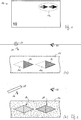
- FIG. 1 shows schematically a bank note 10 with a feature area 12.
- the bank note 10 is the luminescent element.
- the luminescent element it is also possible for the luminescent element to be formed by a separate element which comprises the feature area 12 and which is applied to or introduced onto the bank note 10 or another data carrier.
- the feature area 12 has luminescent properties and, when viewed under a UV lamp, shows a true-colored appearance that differs significantly from its appearance in daylight.
- the changed visual impression allows a simple authenticity check of the banknote 10, but the authenticity feature can only be reproduced with difficulty due to the special combination of a normal motif with a luminescence motif described below and therefore offers a high level of security against forgery.
- FIG. 2 The different visual impression of the feature area 12 in daylight and UV light is shown in FIG Fig. 2 illustrated, whereby Fig. 2 (a) the appearance shows that a viewer 20 is presented in normal artificial or daylight 22, and Fig. 2 (b) shows the appearance that is presented to the viewer 20 after the feature area 12 has been stimulated with UV radiation 26.
- the appearance of the feature area 12 changes significantly: As in FIG Fig. 2 (b) shown, the viewer 20 then sees instead of the two red triangles 14 at the same location, on the one hand, a uniformly white luminescent diamond 16 and, on the other hand, a uniformly orange-green (or red) luminescent diamond 18 in front of the non-luminescent background of banknote paper. As a special feature, the luminescent color of the diamonds 16, 18 extends uniformly both over the area 14 which appears red in daylight and over an area 14i that does not differ from the background in daylight.
- the luminescent hues are not simple spectral colors, but represent complex hues formed from several spectral components, for example white and orange-green (or red) in the exemplary embodiment.
- Orange-green is the name of an orange-tinged green, which is not a mixture from orange and green miss is to be understood.
- the creation of uniform complex color tones in areas with and without a visible color background in particular poses considerable technological problems for potential counterfeiters.
- the human eye is very sensitive to color differences, so that even slight deviations in the luminescent color tones in the areas 14 and 14i can easily be perceived and recognized as an indication of a counterfeit product.
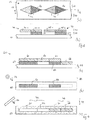
- FIG Fig. 3 explained in more detail, which in (a) a more precise plan view of the feature area 12 of the bank note 10 and in (b) a cross section of the bank note in the feature area 12 along the line BB of FIG Fig. 3 (a) shows.
- the feature area 12 contains on the one hand a normal motif area 30 which is formed by two red imprints 32, 34 in the form of triangles pointing to the right. This normal motif area 30 can be seen in daylight illumination 22 without aids and generates that in FIG Fig. 2 (a) The shown appearance of the feature area 12.
- the feature area 12 also contains a luminescence motif area 40 overlapping the normal motif area 30, which in the exemplary embodiment consists of a left and a right diamond-shaped color area 42 and 46, respectively.
- the color areas 42, 46 are applied with luminescent colors to the bank note paper or to the imprints 32, 34, which are transparent and not visually visible in the visible spectral range and therefore do not appear without UV excitation.
- the left diamond-shaped color area 42 contains a first color subarea 44-1, which adjoins the imprint 32 of the normal motif area 30, but does not overlap with it, and a second color subarea 44-2, which lies above the red imprint 32 of the normal motif area 30.
- the luminescence basic colors luminescence red, luminescence green and luminescence blue are printed in a mixing ratio that generates a white luminescence upon UV excitation.
- the luminescence intensity of the mixed white luminescence color can be lowered or adapted to the luminescence intensity in the area 44-2.
- the three luminescence basic colors mentioned are also used in the second color sub-area 44-2, but the proportion of luminescence red is reduced compared to the first color sub-area 44-1 (and possibly the proportions of luminescence green and luminescence blue are increased) in order to influence the luminescence emission to take into account the red background print 32 and to arrive at the same white luminescence overall as in the first color sub-area 44-1.
- a white fluorescence based on a fluorescent substance e.g. Honeywell CD350
- a uniform white luminescence hue can be obtained for the diamond-shaped color area 42 due to the different mixing ratio of the luminescence basic colors, which each generate a spectral component of the desired luminescence.
- the right diamond-shaped color area 46 contains a first color sub-area 48-1, which adjoins the imprint 34 of the normal motif area 30, but does not overlap with it, and a second color sub-area 48-2, which lies above the red imprint 34 of the normal motif area 30.
- the luminescence basic colors luminescence red, luminescence green and luminescence blue are printed in a mixing ratio that generates an orange-green (or red) luminescence upon UV excitation.
- the three mentioned luminescence basic colors are also used, but in a different mixing ratio than in the color sub-area 48-1, in order to take into account the influence of the luminescence emission by the red imprint 34 and result in the same orange-green ( or red) luminescence as in the first color sub-area 48-1.
- the composition of the luminescent base colors used is modified in the desired direction and test prints with the modified composition are produced.
- the test prints are checked again with the aid of the image acquisition system and, if necessary, a further modification is made.
- This process is repeated until the color tones of the color sub-areas involved have a sufficiently uniform color tone.
- a predetermined threshold value for example 2, 3, 5 or 10.
- the required modification of the composition can be determined, for example, with a computer program which contains, as basic data, the concentration data of the luminescent basic colors involved and the luminescent basic colors with the admixture of the visually visible color.
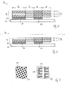
- Figure 4 schematically illustrates a luminescent element 50 according to a further exemplary embodiment of the invention, wherein Fig. 4 (a) the luminescent element 50 in cross section, Fig. 4 (b) the appearance of the luminescent element 50 in plan view in daylight illumination 22 and Fig. 4 (c) the appearance of the luminescent element 50 in a plan view when exposed to UV 26.
- the luminescent element 50 of Fig. 4 contains on a carrier 52 two background prints 54, 56 with a non-fluorescent, visually visible red color, one print 60 with a visually invisible fluorescent color that, together with the red color of the background print 54, produces a white fluorescence, one print 62 with a visually invisible one , white fluorescent fluorescent ink, an imprint 64 of a visually invisible fluorescent ink which, together with the red color of the background imprint 54, generates an orange fluorescence, and an imprint 66 of a visually invisible, orange fluorescent fluorescent ink.
- the imprints 62 and 64 can be applied with the same fluorescent color.
- the red background prints 54, 56 form a normal motif area 30, which can be seen when viewed in daylight 22, as in FIG Fig. 4 (b) shown.
- the imprints 62, 66 provided at the points without a background imprint cannot be visually recognized in daylight; their position is shown in FIG Fig. 4 (b) indicated only by dashed lines.
- the imprints 60-66 form a luminescence motif area 40 which overlaps the normal motif area 30. Specifically, the imprints 60, 64 lie above the background imprints 54, 56 of the normal motif area, while the imprints 62, 66 lie outside the normal motif area.
- a left color area 42 of the luminescence motif area 40 is formed by the imprints 60 and 62.
- the luminescence basic colors are luminescence red, luminescence green and luminescence blue printed in a mixing ratio that produces a white luminescence when excited by UV.
- the luminescence basic colors mentioned are also used in the area of the imprint 60, but the proportion of luminescence red is reduced compared to the imprint 62 in order to take into account the influence of the luminescence by the red background imprint 54 and to achieve the same white color tone of the luminescence as in the area of the Imprint 62 to arrive.
- a right color area 46 of the luminescence motif area 40 is formed by the imprints 64 and 66.
- the luminescence basic colors luminescence red, luminescence green, and luminescence blue are printed in a mixing ratio that generates an orange luminescence upon UV excitation.
- the luminescence basic colors mentioned are also used in the area of the imprint 64, but in a mixing ratio that is modified compared to the imprint 66 in order to take into account the influence of the luminescence by the red background imprint 56 and to the same orange hue of the luminescence as in the area of the imprint 66 to get.
- the appearance of the luminescent element 50 changes significantly, while two spaced red rectangles 54, 56 are visible in daylight illumination, as in FIG Fig. 4 (b) shown, when UV exposure occurs, two larger luminescence areas 42, 46 each with a uniform white or orange-colored luminescence occur at the same location.
- the relative weight of the spectral luminescence components can not only be determined by the mixing ratio of the luminescence basic colors in a homogeneously applied color layer be set, but with particular advantage through the relative area coverage of several full-area or rasterized luminescence basic color layers.
- Figure 5 shows schematically a luminescent element 70 according to the invention in cross section, which when viewed in daylight and when exposed to UV excitation in each case shows the same appearance as the luminescent element 50 of FIG Fig. 4 .
- the luminescent element 70 contains a carrier 52 on which, as in the case of the luminescent element 50, two background prints 54, 56 of a non-fluorescent, visually visible red color are applied, which form the normal motif area 30 of the luminescent element.
- the luminescence motif region 40 is in the exemplary embodiment Fig. 5 formed by a three-layer sequence 72 which comprises a visually invisible, green luminescent color layer 74-G, a visually invisible, red luminescent color layer 74-R, and a visually invisible, blue luminescent color layer 74-B. If all three luminescent color layers are printed over the entire surface, a white luminescent color tone results from additive color mixing after UV excitation.
- one or more of the luminescent color layers 74-G, 74-R, 74-B are printed in areas as a grid and thereby the optically effective area coverage in the different ranges set between 0% and 100% as required.
- the green luminescent color layer 74-G and the blue luminescent color layer 74-B with a high area coverage and the red luminescent color layer 74-R with a low area coverage are applied in area 80, so that in area 80 with UV excitation with the absorption by the background print 54 results in a white luminescent color tone overall.
- the green luminescent color layer 74-G, the blue luminescent color layer 74-B and the red luminescent color layer 74-R are applied with the same, average area coverage, so that a white luminescent color tone results in the area 82 with UV excitation.
- the area coverage of all luminescent color layers is reduced in order to adapt not only the color tone but also the luminescence brightness of the area 82 to the luminescence brightness of the area 80, which cannot assume the maximum possible value due to the absorbent background 54.
- the green luminescent color layer 74-G, the blue luminescent color layer 74-B and the red luminescent color layer 74-R are applied with the same, high surface coverage, so that there is a total of 56 in UV excitation due to the absorption by the background print gives an orange luminescent shade.
- the red luminescent color layer 74-R with high area coverage and the green luminescent color layer 74-G and the blue luminescent color layer 74-B with medium area coverage are applied, so that there is a luminescence with a to area when UV excitation occurs 84 uniform orange hue results in the area coverage there too of the luminescent color layers in order to adapt not only the hue but also the luminescence brightness of the area 86 to the luminescence brightness of the area 84.
- the exact surface coverages of the luminescent color layers are advantageously determined analogously to the procedure described above by a series of test prints, the detection of the luminescent color tones achieved and a modification of the surface coverages.
- the sequence of the luminescent basic color layers can of course also be chosen differently than in the exemplary embodiment. It should be noted, however, that a change in the layer sequence due to a different color acceptance of the colors, absorption effects and scattering usually requires a change in the area coverages in order to obtain the same visual appearance.
- Figure 6 shows a modification of the design of the Fig. 5 , in which only two basic color layers are used in the luminescent element 90 for the layer sequence 92 of the luminescent motif area 40, namely on the one hand a red luminescent color layer 94-R with the luminescent basic color luminescent red, and on the other hand a cyan luminescent color layer 94-C, which is a mixture of the Contains luminescent basic dyes luminescent green and luminescent blue. Due to the additive color mixing, white luminescence can also be achieved by coordinating the area coverages of the red luminescent color layer 94-R and the cyan luminescent color layer 94-C.
- grids of the luminescent color layers all known grid patterns such as point grids, chain grids, frequency-modulated grids or grids of letters, numbers or geometric figures are also possible.
- the grid types can also be combined with one another in partial areas.
- FIG. 7 (a) a simple point grid 100 for one of the luminescent color layers, in which the grid elements of the grid are uniformly formed by small grid points.
- Figure 7 (b) shows a complex motif grid 102 of a luminescent color layer, in which the grid elements 104 are formed by small faces that form a superstructure in the form of the letter "E".
- the raster appears to the naked eye Fig. 6 (b) as uniform area coverage, the letters "E” can be resolved with a magnifying glass and finally the faces of the grid elements 104 can be resolved with a microscope.
- These complex grids can serve as an additional guarantee of authenticity and a hurdle for potential counterfeiters.
Landscapes
- Printing Methods (AREA)
- Credit Cards Or The Like (AREA)
- Luminescent Compositions (AREA)
Applications Claiming Priority (1)
| Application Number | Priority Date | Filing Date | Title |
|---|---|---|---|
| DE102019008116.1A DE102019008116A1 (de) | 2019-11-21 | 2019-11-21 | Lumineszenzelement mit Lumineszenzmotivbereich |
Publications (3)
| Publication Number | Publication Date |
|---|---|
| EP3825141A2 true EP3825141A2 (fr) | 2021-05-26 |
| EP3825141A3 EP3825141A3 (fr) | 2021-06-09 |
| EP3825141B1 EP3825141B1 (fr) | 2022-10-12 |
Family
ID=73288343
Family Applications (1)
| Application Number | Title | Priority Date | Filing Date |
|---|---|---|---|
| EP20020514.4A Active EP3825141B1 (fr) | 2019-11-21 | 2020-11-09 | Element luminescent avec zone de motif luminescente |
Country Status (2)
| Country | Link |
|---|---|
| EP (1) | EP3825141B1 (fr) |
| DE (1) | DE102019008116A1 (fr) |
Cited By (2)
| Publication number | Priority date | Publication date | Assignee | Title |
|---|---|---|---|---|
| WO2022248080A1 (fr) * | 2021-05-27 | 2022-12-01 | Giesecke+Devrient Currency Technology Gmbh | Procédé pour réaliser un marquage de sécurité luminescent et marquage de sécurité luminescent |
| WO2023174469A1 (fr) * | 2022-03-17 | 2023-09-21 | Giesecke+Devrient Currency Technology Gmbh | Procédé de fabrication de documents de valeur et système capteur servant au contrôle de la qualité lors de la fabrication de documents de valeur |
Families Citing this family (3)
| Publication number | Priority date | Publication date | Assignee | Title |
|---|---|---|---|---|
| DE102021002764A1 (de) | 2021-05-27 | 2022-12-01 | Giesecke+Devrient Currency Technology Gmbh | Verfahren zur Herstellung einer lumineszenten Druckfarbe |
| DE102023118604A1 (de) * | 2023-07-13 | 2025-01-16 | Giesecke+Devrient Currency Technology Gmbh | Wertdokument und Verfahren zur Prüfung eines Wertdokuments |
| DE102024103599A1 (de) | 2024-02-08 | 2025-08-14 | Giesecke+Devrient Currency Technology Gmbh | Sicherheitselement und Verfahren zur Herstellung eines Sicherheitselements |
Citations (1)
| Publication number | Priority date | Publication date | Assignee | Title |
|---|---|---|---|---|
| EP3513984A1 (fr) | 2018-01-17 | 2019-07-24 | Giesecke+Devrient Currency Technology GmbH | Élément de sécurité pourvu de zone luminescente à motif |
Family Cites Families (5)
| Publication number | Priority date | Publication date | Assignee | Title |
|---|---|---|---|---|
| US7422158B2 (en) * | 2003-10-24 | 2008-09-09 | Pitney Bowes Inc. | Fluorescent hidden indicium |
| US7926730B2 (en) * | 2005-11-30 | 2011-04-19 | Pitney Bowes Inc. | Combined multi-spectral document markings |
| JP5622087B2 (ja) * | 2010-08-09 | 2014-11-12 | 大日本印刷株式会社 | 発光媒体 |
| DE102017004037B4 (de) * | 2017-04-26 | 2019-06-27 | Mühlbauer Gmbh & Co. Kg | Sicherheitseinlage mit einer Vertiefung für ein Ausweisdokument und Verfahren zur Herstellung einer Sicherheitseinlage mit einer Vertiefung für ein Ausweisdokument |
| DE102017127923A1 (de) * | 2017-11-27 | 2019-06-13 | Bundesdruckerei Gmbh | Codierungssystem zum Ausbilden eines Sicherheitsmerkmals in oder an einem Sicherheits- oder Wertdokument oder einer Mehrzahl von Sicherheits- oder Wertdokumenten |
-
2019
- 2019-11-21 DE DE102019008116.1A patent/DE102019008116A1/de not_active Withdrawn
-
2020
- 2020-11-09 EP EP20020514.4A patent/EP3825141B1/fr active Active
Patent Citations (1)
| Publication number | Priority date | Publication date | Assignee | Title |
|---|---|---|---|---|
| EP3513984A1 (fr) | 2018-01-17 | 2019-07-24 | Giesecke+Devrient Currency Technology GmbH | Élément de sécurité pourvu de zone luminescente à motif |
Cited By (3)
| Publication number | Priority date | Publication date | Assignee | Title |
|---|---|---|---|---|
| WO2022248080A1 (fr) * | 2021-05-27 | 2022-12-01 | Giesecke+Devrient Currency Technology Gmbh | Procédé pour réaliser un marquage de sécurité luminescent et marquage de sécurité luminescent |
| US12151501B2 (en) | 2021-05-27 | 2024-11-26 | Giesecke+Devrient Currency Technology Gmbh | Method for producing a luminescent security marking and luminescent security marking |
| WO2023174469A1 (fr) * | 2022-03-17 | 2023-09-21 | Giesecke+Devrient Currency Technology Gmbh | Procédé de fabrication de documents de valeur et système capteur servant au contrôle de la qualité lors de la fabrication de documents de valeur |
Also Published As
| Publication number | Publication date |
|---|---|
| EP3825141B1 (fr) | 2022-10-12 |
| DE102019008116A1 (de) | 2021-05-27 |
| EP3825141A3 (fr) | 2021-06-09 |
Similar Documents
| Publication | Publication Date | Title |
|---|---|---|
| EP3825141B1 (fr) | Element luminescent avec zone de motif luminescente | |
| EP2323852B1 (fr) | Élément de sécurité comportant des informations en lumière réfléchie et en lumière transmise | |
| EP2121348B1 (fr) | Élément de sécurité pour document de valeur | |
| EP2643161B1 (fr) | Document de valeur et/ou de sécurité présentant une caractéristique de sécurité colorée transparente, ainsi que son procédé de fabrication | |
| EP2920004B1 (fr) | Élément de sécurité pour un document de valeur et/ou de sécurité | |
| EP2643162B1 (fr) | Document de valeur et/ou de sécurité, ainsi que son procédé de fabrication | |
| EP3513984B2 (fr) | Élément de sécurité pourvu de zone luminescente à motif | |
| EP3452299B1 (fr) | Élément de sécurité doté d'une impression luminescente | |
| EP3225417B1 (fr) | Support de données doté d'une impression | |
| EP3168052A1 (fr) | Élément de sécurité | |
| DE102019006315A1 (de) | Optisch variables Sicherheitselement | |
| DE102007045137B3 (de) | Sicherheitsdokument mit einem Gültigkeitsmerkmal sowie Verfahren zu dessen Herstellung und Vorrichtung zur Überprüfung | |
| EP2678170A2 (fr) | Impression simultanée individualisée | |
| EP3339049A1 (fr) | Support de données avec des zones luminescentes | |
| EP4049852B1 (fr) | Élément de sécurité, support de données et procédé de fabrication | |
| DE102014004753A1 (de) | Sicherheitselement mit lumineszierendem Sicherheitsmerkmal | |
| EP3693181B1 (fr) | Document d'identification et procédé de fabrication d'un document d'identification | |
| DE102021002759A1 (de) | Verfahren zur Erzeugung einer lumineszenten Sicherheitsmarkierung und lumineszente Sicherheitsmarkierung | |
| EP2356615A1 (fr) | Élément de sécurité avec codage lisible par machine | |
| EP4183592B1 (fr) | Élément de sécurité transparent et procédé de fabrication | |
| DE102023126444A1 (de) | Sicherheitselement mit lumineszierendem Sicherheitsmerkmal | |
| EP4520544A1 (fr) | Document de valeur et procédé de fabrication d'un document de valeur | |
| EP4254369A1 (fr) | Document de valeur, son procédé de fabrication et procédé de vérification | |
| AT403451B (de) | Einrichtung zur erzeugung und sichtbarmachung von lichteffekten |
Legal Events
| Date | Code | Title | Description |
|---|---|---|---|
| PUAI | Public reference made under article 153(3) epc to a published international application that has entered the european phase |
Free format text: ORIGINAL CODE: 0009012 |
|
| STAA | Information on the status of an ep patent application or granted ep patent |
Free format text: STATUS: THE APPLICATION HAS BEEN PUBLISHED |
|
| PUAL | Search report despatched |
Free format text: ORIGINAL CODE: 0009013 |
|
| AK | Designated contracting states |
Kind code of ref document: A2 Designated state(s): AL AT BE BG CH CY CZ DE DK EE ES FI FR GB GR HR HU IE IS IT LI LT LU LV MC MK MT NL NO PL PT RO RS SE SI SK SM TR |
|
| AK | Designated contracting states |
Kind code of ref document: A3 Designated state(s): AL AT BE BG CH CY CZ DE DK EE ES FI FR GB GR HR HU IE IS IT LI LT LU LV MC MK MT NL NO PL PT RO RS SE SI SK SM TR |
|
| RIC1 | Information provided on ipc code assigned before grant |
Ipc: B42D 25/382 20140101AFI20210503BHEP Ipc: B42D 25/387 20140101ALI20210503BHEP Ipc: B42D 25/351 20140101ALI20210503BHEP |
|
| STAA | Information on the status of an ep patent application or granted ep patent |
Free format text: STATUS: REQUEST FOR EXAMINATION WAS MADE |
|
| 17P | Request for examination filed |
Effective date: 20211209 |
|
| RBV | Designated contracting states (corrected) |
Designated state(s): AL AT BE BG CH CY CZ DE DK EE ES FI FR GB GR HR HU IE IS IT LI LT LU LV MC MK MT NL NO PL PT RO RS SE SI SK SM TR |
|
| GRAP | Despatch of communication of intention to grant a patent |
Free format text: ORIGINAL CODE: EPIDOSNIGR1 |
|
| STAA | Information on the status of an ep patent application or granted ep patent |
Free format text: STATUS: GRANT OF PATENT IS INTENDED |
|
| INTG | Intention to grant announced |
Effective date: 20220512 |
|
| GRAS | Grant fee paid |
Free format text: ORIGINAL CODE: EPIDOSNIGR3 |
|
| GRAA | (expected) grant |
Free format text: ORIGINAL CODE: 0009210 |
|
| STAA | Information on the status of an ep patent application or granted ep patent |
Free format text: STATUS: THE PATENT HAS BEEN GRANTED |
|
| AK | Designated contracting states |
Kind code of ref document: B1 Designated state(s): AL AT BE BG CH CY CZ DE DK EE ES FI FR GB GR HR HU IE IS IT LI LT LU LV MC MK MT NL NO PL PT RO RS SE SI SK SM TR |
|
| REG | Reference to a national code |
Ref country code: GB Ref legal event code: FG4D Free format text: NOT ENGLISH |
|
| REG | Reference to a national code |
Ref country code: CH Ref legal event code: EP |
|
| REG | Reference to a national code |
Ref country code: DE Ref legal event code: R096 Ref document number: 502020001813 Country of ref document: DE |
|
| REG | Reference to a national code |
Ref country code: IE Ref legal event code: FG4D Free format text: LANGUAGE OF EP DOCUMENT: GERMAN |
|
| REG | Reference to a national code |
Ref country code: AT Ref legal event code: REF Ref document number: 1523932 Country of ref document: AT Kind code of ref document: T Effective date: 20221115 |
|
| REG | Reference to a national code |
Ref country code: LT Ref legal event code: MG9D |
|
| REG | Reference to a national code |
Ref country code: NL Ref legal event code: MP Effective date: 20221012 |
|
| RAP4 | Party data changed (patent owner data changed or rights of a patent transferred) |
Owner name: GIESECKE+DEVRIENT CURRENCY TECHNOLOGY GMBH |
|
| PG25 | Lapsed in a contracting state [announced via postgrant information from national office to epo] |
Ref country code: NL Free format text: LAPSE BECAUSE OF FAILURE TO SUBMIT A TRANSLATION OF THE DESCRIPTION OR TO PAY THE FEE WITHIN THE PRESCRIBED TIME-LIMIT Effective date: 20221012 |
|
| PG25 | Lapsed in a contracting state [announced via postgrant information from national office to epo] |
Ref country code: SE Free format text: LAPSE BECAUSE OF FAILURE TO SUBMIT A TRANSLATION OF THE DESCRIPTION OR TO PAY THE FEE WITHIN THE PRESCRIBED TIME-LIMIT Effective date: 20221012 Ref country code: PT Free format text: LAPSE BECAUSE OF FAILURE TO SUBMIT A TRANSLATION OF THE DESCRIPTION OR TO PAY THE FEE WITHIN THE PRESCRIBED TIME-LIMIT Effective date: 20230213 Ref country code: NO Free format text: LAPSE BECAUSE OF FAILURE TO SUBMIT A TRANSLATION OF THE DESCRIPTION OR TO PAY THE FEE WITHIN THE PRESCRIBED TIME-LIMIT Effective date: 20230112 Ref country code: LT Free format text: LAPSE BECAUSE OF FAILURE TO SUBMIT A TRANSLATION OF THE DESCRIPTION OR TO PAY THE FEE WITHIN THE PRESCRIBED TIME-LIMIT Effective date: 20221012 Ref country code: FI Free format text: LAPSE BECAUSE OF FAILURE TO SUBMIT A TRANSLATION OF THE DESCRIPTION OR TO PAY THE FEE WITHIN THE PRESCRIBED TIME-LIMIT Effective date: 20221012 Ref country code: ES Free format text: LAPSE BECAUSE OF FAILURE TO SUBMIT A TRANSLATION OF THE DESCRIPTION OR TO PAY THE FEE WITHIN THE PRESCRIBED TIME-LIMIT Effective date: 20221012 |
|
| PG25 | Lapsed in a contracting state [announced via postgrant information from national office to epo] |
Ref country code: RS Free format text: LAPSE BECAUSE OF FAILURE TO SUBMIT A TRANSLATION OF THE DESCRIPTION OR TO PAY THE FEE WITHIN THE PRESCRIBED TIME-LIMIT Effective date: 20221012 Ref country code: PL Free format text: LAPSE BECAUSE OF FAILURE TO SUBMIT A TRANSLATION OF THE DESCRIPTION OR TO PAY THE FEE WITHIN THE PRESCRIBED TIME-LIMIT Effective date: 20221012 Ref country code: LV Free format text: LAPSE BECAUSE OF FAILURE TO SUBMIT A TRANSLATION OF THE DESCRIPTION OR TO PAY THE FEE WITHIN THE PRESCRIBED TIME-LIMIT Effective date: 20221012 Ref country code: IS Free format text: LAPSE BECAUSE OF FAILURE TO SUBMIT A TRANSLATION OF THE DESCRIPTION OR TO PAY THE FEE WITHIN THE PRESCRIBED TIME-LIMIT Effective date: 20230212 Ref country code: HR Free format text: LAPSE BECAUSE OF FAILURE TO SUBMIT A TRANSLATION OF THE DESCRIPTION OR TO PAY THE FEE WITHIN THE PRESCRIBED TIME-LIMIT Effective date: 20221012 Ref country code: GR Free format text: LAPSE BECAUSE OF FAILURE TO SUBMIT A TRANSLATION OF THE DESCRIPTION OR TO PAY THE FEE WITHIN THE PRESCRIBED TIME-LIMIT Effective date: 20230113 |
|
| REG | Reference to a national code |
Ref country code: DE Ref legal event code: R119 Ref document number: 502020001813 Country of ref document: DE |
|
| P01 | Opt-out of the competence of the unified patent court (upc) registered |
Effective date: 20230520 |
|
| REG | Reference to a national code |
Ref country code: BE Ref legal event code: MM Effective date: 20221130 |
|
| PG25 | Lapsed in a contracting state [announced via postgrant information from national office to epo] |
Ref country code: SM Free format text: LAPSE BECAUSE OF FAILURE TO SUBMIT A TRANSLATION OF THE DESCRIPTION OR TO PAY THE FEE WITHIN THE PRESCRIBED TIME-LIMIT Effective date: 20221012 Ref country code: RO Free format text: LAPSE BECAUSE OF FAILURE TO SUBMIT A TRANSLATION OF THE DESCRIPTION OR TO PAY THE FEE WITHIN THE PRESCRIBED TIME-LIMIT Effective date: 20221012 Ref country code: MC Free format text: LAPSE BECAUSE OF FAILURE TO SUBMIT A TRANSLATION OF THE DESCRIPTION OR TO PAY THE FEE WITHIN THE PRESCRIBED TIME-LIMIT Effective date: 20221012 Ref country code: EE Free format text: LAPSE BECAUSE OF FAILURE TO SUBMIT A TRANSLATION OF THE DESCRIPTION OR TO PAY THE FEE WITHIN THE PRESCRIBED TIME-LIMIT Effective date: 20221012 Ref country code: DK Free format text: LAPSE BECAUSE OF FAILURE TO SUBMIT A TRANSLATION OF THE DESCRIPTION OR TO PAY THE FEE WITHIN THE PRESCRIBED TIME-LIMIT Effective date: 20221012 Ref country code: CZ Free format text: LAPSE BECAUSE OF FAILURE TO SUBMIT A TRANSLATION OF THE DESCRIPTION OR TO PAY THE FEE WITHIN THE PRESCRIBED TIME-LIMIT Effective date: 20221012 |
|
| PLBE | No opposition filed within time limit |
Free format text: ORIGINAL CODE: 0009261 |
|
| STAA | Information on the status of an ep patent application or granted ep patent |
Free format text: STATUS: NO OPPOSITION FILED WITHIN TIME LIMIT |
|
| PG25 | Lapsed in a contracting state [announced via postgrant information from national office to epo] |
Ref country code: SK Free format text: LAPSE BECAUSE OF FAILURE TO SUBMIT A TRANSLATION OF THE DESCRIPTION OR TO PAY THE FEE WITHIN THE PRESCRIBED TIME-LIMIT Effective date: 20221012 Ref country code: LU Free format text: LAPSE BECAUSE OF NON-PAYMENT OF DUE FEES Effective date: 20221109 Ref country code: AL Free format text: LAPSE BECAUSE OF FAILURE TO SUBMIT A TRANSLATION OF THE DESCRIPTION OR TO PAY THE FEE WITHIN THE PRESCRIBED TIME-LIMIT Effective date: 20221012 |
|
| 26N | No opposition filed |
Effective date: 20230713 |
|
| PG25 | Lapsed in a contracting state [announced via postgrant information from national office to epo] |
Ref country code: IE Free format text: LAPSE BECAUSE OF NON-PAYMENT OF DUE FEES Effective date: 20221109 Ref country code: DE Free format text: LAPSE BECAUSE OF NON-PAYMENT OF DUE FEES Effective date: 20230601 |
|
| PG25 | Lapsed in a contracting state [announced via postgrant information from national office to epo] |
Ref country code: SI Free format text: LAPSE BECAUSE OF FAILURE TO SUBMIT A TRANSLATION OF THE DESCRIPTION OR TO PAY THE FEE WITHIN THE PRESCRIBED TIME-LIMIT Effective date: 20221012 Ref country code: BE Free format text: LAPSE BECAUSE OF NON-PAYMENT OF DUE FEES Effective date: 20221130 |
|
| PG25 | Lapsed in a contracting state [announced via postgrant information from national office to epo] |
Ref country code: CY Free format text: LAPSE BECAUSE OF FAILURE TO SUBMIT A TRANSLATION OF THE DESCRIPTION OR TO PAY THE FEE WITHIN THE PRESCRIBED TIME-LIMIT Effective date: 20221012 |
|
| PG25 | Lapsed in a contracting state [announced via postgrant information from national office to epo] |
Ref country code: MK Free format text: LAPSE BECAUSE OF FAILURE TO SUBMIT A TRANSLATION OF THE DESCRIPTION OR TO PAY THE FEE WITHIN THE PRESCRIBED TIME-LIMIT Effective date: 20221012 Ref country code: IT Free format text: LAPSE BECAUSE OF FAILURE TO SUBMIT A TRANSLATION OF THE DESCRIPTION OR TO PAY THE FEE WITHIN THE PRESCRIBED TIME-LIMIT Effective date: 20221012 |
|
| PG25 | Lapsed in a contracting state [announced via postgrant information from national office to epo] |
Ref country code: TR Free format text: LAPSE BECAUSE OF FAILURE TO SUBMIT A TRANSLATION OF THE DESCRIPTION OR TO PAY THE FEE WITHIN THE PRESCRIBED TIME-LIMIT Effective date: 20221012 |
|
| REG | Reference to a national code |
Ref country code: CH Ref legal event code: PL |
|
| PG25 | Lapsed in a contracting state [announced via postgrant information from national office to epo] |
Ref country code: CH Free format text: LAPSE BECAUSE OF NON-PAYMENT OF DUE FEES Effective date: 20231130 |
|
| PG25 | Lapsed in a contracting state [announced via postgrant information from national office to epo] |
Ref country code: HU Free format text: LAPSE BECAUSE OF FAILURE TO SUBMIT A TRANSLATION OF THE DESCRIPTION OR TO PAY THE FEE WITHIN THE PRESCRIBED TIME-LIMIT; INVALID AB INITIO Effective date: 20201109 Ref country code: CH Free format text: LAPSE BECAUSE OF NON-PAYMENT OF DUE FEES Effective date: 20231130 Ref country code: BG Free format text: LAPSE BECAUSE OF FAILURE TO SUBMIT A TRANSLATION OF THE DESCRIPTION OR TO PAY THE FEE WITHIN THE PRESCRIBED TIME-LIMIT Effective date: 20221012 |
|
| PGFP | Annual fee paid to national office [announced via postgrant information from national office to epo] |
Ref country code: GB Payment date: 20251120 Year of fee payment: 6 |
|
| PGFP | Annual fee paid to national office [announced via postgrant information from national office to epo] |
Ref country code: AT Payment date: 20260113 Year of fee payment: 5 |
|
| PGFP | Annual fee paid to national office [announced via postgrant information from national office to epo] |
Ref country code: FR Payment date: 20251120 Year of fee payment: 6 |
|
| PGFP | Annual fee paid to national office [announced via postgrant information from national office to epo] |
Ref country code: MT Payment date: 20251124 Year of fee payment: 6 |