EP3825478B1 - Abflusssieb für eine ablaufleitung - Google Patents
Abflusssieb für eine ablaufleitung Download PDFInfo
- Publication number
- EP3825478B1 EP3825478B1 EP19383032.0A EP19383032A EP3825478B1 EP 3825478 B1 EP3825478 B1 EP 3825478B1 EP 19383032 A EP19383032 A EP 19383032A EP 3825478 B1 EP3825478 B1 EP 3825478B1
- Authority
- EP
- European Patent Office
- Prior art keywords
- accumulating container
- waste
- waste accumulating
- holes
- drainpipe
- Prior art date
- Legal status (The legal status is an assumption and is not a legal conclusion. Google has not performed a legal analysis and makes no representation as to the accuracy of the status listed.)
- Active
Links
Images

Classifications
-
- E—FIXED CONSTRUCTIONS
- E03—WATER SUPPLY; SEWERAGE
- E03C—DOMESTIC PLUMBING INSTALLATIONS FOR FRESH WATER OR WASTE WATER; SINKS
- E03C1/00—Domestic plumbing installations for fresh water or waste water; Sinks
- E03C1/12—Plumbing installations for waste water; Basins or fountains connected thereto; Sinks
- E03C1/28—Odour seals
- E03C1/282—Odour seals combined with additional object-catching devices
-
- E—FIXED CONSTRUCTIONS
- E03—WATER SUPPLY; SEWERAGE
- E03C—DOMESTIC PLUMBING INSTALLATIONS FOR FRESH WATER OR WASTE WATER; SINKS
- E03C1/00—Domestic plumbing installations for fresh water or waste water; Sinks
- E03C1/12—Plumbing installations for waste water; Basins or fountains connected thereto; Sinks
- E03C1/26—Object-catching inserts or similar devices for waste pipes or outlets
- E03C1/264—Separate sieves or similar object-catching inserts
-
- E—FIXED CONSTRUCTIONS
- E03—WATER SUPPLY; SEWERAGE
- E03C—DOMESTIC PLUMBING INSTALLATIONS FOR FRESH WATER OR WASTE WATER; SINKS
- E03C1/00—Domestic plumbing installations for fresh water or waste water; Sinks
- E03C1/12—Plumbing installations for waste water; Basins or fountains connected thereto; Sinks
- E03C1/28—Odour seals
- E03C1/29—Odour seals having housing containing dividing wall, e.g. tubular
Definitions
- the present invention relates to the field of surface drains useful for floor drains, kitchen and bathroom sinks, bathtubs, and showers.
- the invention relates to a device for straining and accumulate material sloughed into wastewater such as hair while bathing.
- US7150576 escribes a drain strainer comprising a drain plate, a sleeve and a basket, coaxially mountable in a generally cylindrical drain pipe; the basket has a plurality of holes disposed circumferentially and the sleeve having an open bottom in such a way the drain water flow openings in the basket before traversing the flow openings and entering the drainpipe. Because of the relative disposition between the sleeve and the basket the drain also has the function of a syphon. This proposal doesn't allow the debris to be retained away from the accumulated water, due to the bottom of the sleeve is submerged in the water retained by the basket and the basket could contain water inside. This proposal is not easily removable and in other hand the disclosed embodiment does not include any element which gives a perfume during use.
- Document KR20050095067A relates to a sewage pipe deodorizer and waste trap device comprising a coupling hole into which a sewer pipe is inserted and fixed, a locking protrusion formed on the coupling hole, and an accommodating space for accommodating water formed on the outer periphery of the locking protrusion.
- the device is fixed to the frame and inserted into the sewer pipe and has an open upper part, a fixing jaw formed on the upper rim to be fixed to the stopping jaw, and a sealing membrane formed on the lower side of the stopping jaw to be sealed with the stopping jaw.
- the siphon comprises a siphon body in which is mounted a removable perforated basket for collecting debris, said basket, preferably in the form of a cylindrical container, is supported by its bottom or by its edge in an intermediate tubular part resting by a collar on the bottom of the sink and which screws into the body of the siphon, which is thus blocked against the bottom of the sink.
- the siphon body comprises a lateral water discharge orifice situated at a sufficient height above the bottom of the siphon body to provide the desirable water seal.
- a drain strainer for a drain pipe of a bathtub or of a shower that comprises a first waste accumulating container which has a tubular shape, this first waste accumulating container is open by the two ends (top and bottom parts) and comprises inside it in a transversal wall a first plane of holes, that is designed to filter or to strain and also to retain particles of collected waste material mainly hair debris.
- This first plane of holes in the transversal wall has a plurality of small holes.
- this first plane of holes consists of a sieve or a strainer very porous.
- the drain strainer of the invention also comprises a second waste accumulating container that consist of a waste with tubular shape that has one and open and the other end closed, wherein this closed end defines a bottom, in such a way that the flow water could be retained in the bottom of the second waste accumulating container.
- the second waste accumulating container also comprises a plurality of holes through a side wall of the second waste accumulating container, the holes being defined at a distance of said bottom.
- the low raw of the plurality of holes defines a maximum level of accumulating water inside said second waste accumulating container. That means that after a flow of water enters the drain strainer the water will be retained in the second waste accumulating container that is limited in height by the low raw of the plurality of holes of the second waste accumulating container.
- the first waste accumulating container is nested and held by the second waste accumulating container and preferably includes a tab for hand removal.
- One of the characteristics of the drain strainer in one preferred embodiment is the fact of being easily removable and able to be disposable in particular by the materials used in its manufacture.
- the first waste accumulating container is nested and held by the second waste accumulating container and according to the invention are coaxially located between them and within the drainpipe.
- the first waste accumulating container and the second waste accumulating container, according to the invention are held by a first annular sealing element and the second waste accumulating container are also held with the drain pipe by a second annular sealing element, and these first and second annular sealing element are deodorant impregnated.
- This first and second annular sealing element are in a first portion of the drain strainer above and distanced of the planes of holes of the first waste accumulating container.
- the lower end of the first waste accumulating container define a lower tubular portion that is located below the maximum level of accumulating water and this arrangement define a syphon.
- references to geometric position such as parallel, perpendicular, tangent, etc. allow deviations up to ⁇ 5° from the theoretical position defined by this nomenclature.
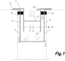
- FIG. 1 shows a cross-section of the drain strainer for a drainpipe 6 that comprises a first waste accumulating container 1 nested a second waste accumulating container 2 and both nested and coaxially mounted in a drainpipe 6.
- the first and second waste accumulating container 1,2 and the drainpipe 6 are also in contact through a first and a second annular sealing elements 5,8 respectively.
- the first waste accumulating container 1 has a first plane of holes 3 in a transverse wall that defines a bottom inside the first waste accumulating container 1 (in a middle region thereof) and a tab 10 for hand removal located in the upper part of the first waste accumulating container 1 foldable to the inside and the lowest part of the first waste accumulating container 1 defines a lower tubular portion 9.
- the second waste accumulating container 2 has a second plurality of holes 4 through a side wall 7 that define a ring coaxial with the first and the second waste accumulating container 1,2.
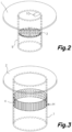
- Fig. 2 shows a perspective view of the first waste accumulating container 1 of Fig. 1 having a cylinder shaped that comprises one tab 10 (for example pliable to the inside and deployable) for hand removal located in the top of the first waste accumulating container 1. Also show in the interior of the first waste accumulating container 1 is a first plane of holes 3 and below the first plane of holes 3 shows a tubular portion 9 that is open.
- Fig. 3 shows a perspective view of the second waste accumulating container 2 having a tubular shape with an end closed, that comprises a second plurality of holes 4 through a side wall 7 coaxial with the first and the second waste accumulating container 1,2.
- the low part of the second plurality of holes 4 defines a maximum level of accumulating water (H) inside said second waste accumulating container 2.
- Fig. 4 is a top view of the drain strainer including the referred first and second waste accumulating containers 1,2 of a tubular shape and having a coaxial arrangement. The top view also shows the first plane of holes 3 at the bottom of the first waste accumulating container 1, and a tab 10 for hand removal.
- Fig. 5 is is a perspective view of the first and second annular sealing elements 1,2 having a ring form and coaxially mounted between first and second waste accumulating containers 1, 2.
Landscapes
- Engineering & Computer Science (AREA)
- Environmental & Geological Engineering (AREA)
- Health & Medical Sciences (AREA)
- Life Sciences & Earth Sciences (AREA)
- Hydrology & Water Resources (AREA)
- Public Health (AREA)
- Water Supply & Treatment (AREA)
- Sink And Installation For Waste Water (AREA)
Claims (3)
- Abflusssieb für eine Ablaufleitung (6), das einen ersten Abfallsammelbehälter (1) mit einer Röhrenform aufweist, der einen Boden mit einer ersten Vielzahl von Löchern aufweist, die eine erste Ebene von Löchern (3) bilden, wobei der erste Abfallsammelbehälter (1) in einen zweiten Abfallsammelbehälter (2) eingesetzt ist und von diesem gehalten wird, der eine zweite Vielzahl von Löchern (4) durch eine Seitenwand (7) des zweiten Abfallsammelbehälters (2) aufweist, die den ersten Abfallsammelbehälter (1) umgibt, wobei ein unteres Ende der zweiten Vielzahl von Löchern (4) einen maximalen Pegel an sich ansammelndem Speicherwasser (H) innerhalb des zweiten Abfallsammelbehälters (2) definiert, wobei der erste und der zweite Abfallsammelbehälter (1, 2) koaxial sind, wobeider erste Abfallsammelbehälter (1) einen unteren rohrförmigen Abschnitt (9) aufweist, der sich unter dem Boden befindet;eine Öffnung des rohrförmigen Abschnitts (9) und eine Seitenwand des rohrförmigen Abschnitts (9) eine Siphonanordnung in Bezug auf die Seitenwand (7) definieren, die die zweite Vielzahl von Löchern (4) aufweist; die erste Ebene von Löchern (3) über dem maximalen Pegel des sich ansammelnden Wassers (H) angeordnet ist, so dass jeglicher Schmutz auf dem Boden weg von dem sich ansammelnden Wasser zurückgehalten wird; ein erstes ringförmiges Dichtungselement (5) koaxial zwischen dem ersten und dem zweiten Abfallsammelbehälter (1, 2) angeordnet ist und ein zweites ringförmiges Dichtungselement (8) koaxial zwischen dem zweiten Abfallsammelbehälter (2) und dem Abflussrohr (6) anordenbar ist;sowohl das erste als auch das zweite ringförmige Dichtungselement (5, 8) in einem ersten Abschnitt des Abflusssiebs über der ersten Ebene der Löcher (3) angeordnet sind; unddas erste und zweite ringförmige Dichtungselement (5, 8) mit Deodorant imprägniert sind.
- Abflusssieb für eine Ablaufleitung (6) nach Anspruch 1, das eine Lasche (10) zum Entfernen beinhaltet, die an dem ersten Abfallsammelbehälter (1) befestigt ist.
- Abflusssieb für eine Ablaufleitung (6) nach Anspruch 1, wobei der zweite Abfallsammelbehälter (2) koaxial innerhalb des Abflussrohrs (6) montierbar ist und wobei das Abflussrohr (6) im Allgemeinen zylindrisch ist.
Priority Applications (2)
| Application Number | Priority Date | Filing Date | Title |
|---|---|---|---|
| ES19383032T ES3004340T3 (en) | 2019-11-22 | 2019-11-22 | Drain strainer for a drainpipe |
| EP19383032.0A EP3825478B1 (de) | 2019-11-22 | 2019-11-22 | Abflusssieb für eine ablaufleitung |
Applications Claiming Priority (1)
| Application Number | Priority Date | Filing Date | Title |
|---|---|---|---|
| EP19383032.0A EP3825478B1 (de) | 2019-11-22 | 2019-11-22 | Abflusssieb für eine ablaufleitung |
Publications (3)
| Publication Number | Publication Date |
|---|---|
| EP3825478A1 EP3825478A1 (de) | 2021-05-26 |
| EP3825478C0 EP3825478C0 (de) | 2024-11-13 |
| EP3825478B1 true EP3825478B1 (de) | 2024-11-13 |
Family
ID=68808235
Family Applications (1)
| Application Number | Title | Priority Date | Filing Date |
|---|---|---|---|
| EP19383032.0A Active EP3825478B1 (de) | 2019-11-22 | 2019-11-22 | Abflusssieb für eine ablaufleitung |
Country Status (2)
| Country | Link |
|---|---|
| EP (1) | EP3825478B1 (de) |
| ES (1) | ES3004340T3 (de) |
Families Citing this family (1)
| Publication number | Priority date | Publication date | Assignee | Title |
|---|---|---|---|---|
| CN114135251B (zh) * | 2021-12-01 | 2024-09-20 | 赵世斌 | 一种岩土工程抗浮疏排水装置 |
Family Cites Families (7)
| Publication number | Priority date | Publication date | Assignee | Title |
|---|---|---|---|---|
| US2285833A (en) | 1938-01-27 | 1942-06-09 | Isabelle R Platt | Disposable drain strainer |
| FR1190383A (fr) * | 1958-01-23 | 1959-10-12 | Siphon pour éviers, timbres d'offices et usages analogues | |
| US3516541A (en) * | 1968-11-07 | 1970-06-23 | David D Coles | Drain safety device |
| WO1999027199A1 (en) * | 1997-11-19 | 1999-06-03 | Ian Alexander Mackay | Drain assembly |
| KR20050095067A (ko) * | 2004-03-24 | 2005-09-29 | 조웅규 | 하수관 냄새제거 및 오물 걸림장치 |
| US7150576B1 (en) | 2005-03-15 | 2006-12-19 | Kambeyanda Dona M | Clog resistant drain |
| CA2675165A1 (en) * | 2007-01-11 | 2008-07-17 | Trilaur Pty Ltd | A drain fitting |
-
2019
- 2019-11-22 ES ES19383032T patent/ES3004340T3/es active Active
- 2019-11-22 EP EP19383032.0A patent/EP3825478B1/de active Active
Also Published As
| Publication number | Publication date |
|---|---|
| EP3825478C0 (de) | 2024-11-13 |
| EP3825478A1 (de) | 2021-05-26 |
| ES3004340T3 (en) | 2025-03-12 |
Similar Documents
| Publication | Publication Date | Title |
|---|---|---|
| US20080169228A1 (en) | Filter assembly | |
| US20120012510A1 (en) | Filter and filter assembly | |
| AU3177299A (en) | Waste outlet | |
| KR101699850B1 (ko) | 욕조용 배수트랩 | |
| KR200457073Y1 (ko) | 배수트랩 | |
| EP3825478A1 (de) | Abflusssieb für eine ablaufleitung | |
| KR200368837Y1 (ko) | 착탈식 걸름망이 구비된 세면기용 배수전 | |
| KR102191917B1 (ko) | 층상배관용 배수트랩 | |
| KR20200103449A (ko) | 막힘 방지 기능이 부여된 배수구용 거름망 구조 | |
| KR101690457B1 (ko) | 배수 트랩 | |
| KR100654576B1 (ko) | 배수구용 이물질 걸름장치 | |
| JP6194507B2 (ja) | 封水式排水トラップ | |
| KR200352206Y1 (ko) | 배수트랩 | |
| JP5106897B2 (ja) | 排水トラップにおける目皿 | |
| KR200484438Y1 (ko) | 필터부를 구비한 벨모양 배수트랩 | |
| KR200230642Y1 (ko) | 하수구 덮개 | |
| AU2007100030A4 (en) | Filter assembly | |
| KR20210082780A (ko) | 배수 트랩 | |
| GB2254013A (en) | Waste outlet filter | |
| KR102688665B1 (ko) | 거름장치가 구비된 세면대 | |
| JP5956129B2 (ja) | インナーおよびインナーを備えた排水トラップ | |
| KR200314070Y1 (ko) | 배수트랩 | |
| KR20160057135A (ko) | 배수트랩용 이물질 걸름부재 | |
| KR200169068Y1 (ko) | 욕실용 배수장치 | |
| KR20190142944A (ko) | 배수구의 이물질 제거용 연결 장치 |
Legal Events
| Date | Code | Title | Description |
|---|---|---|---|
| PUAI | Public reference made under article 153(3) epc to a published international application that has entered the european phase |
Free format text: ORIGINAL CODE: 0009012 |
|
| STAA | Information on the status of an ep patent application or granted ep patent |
Free format text: STATUS: THE APPLICATION HAS BEEN PUBLISHED |
|
| AK | Designated contracting states |
Kind code of ref document: A1 Designated state(s): AL AT BE BG CH CY CZ DE DK EE ES FI FR GB GR HR HU IE IS IT LI LT LU LV MC MK MT NL NO PL PT RO RS SE SI SK SM TR |
|
| STAA | Information on the status of an ep patent application or granted ep patent |
Free format text: STATUS: REQUEST FOR EXAMINATION WAS MADE |
|
| RBV | Designated contracting states (corrected) |
Designated state(s): AL AT BE BG CH CY CZ DE DK EE ES FI FR GB GR HR HU IE IS IT LI LT LU LV MC MK MT NL NO PL PT RO RS SE SI SK SM TR |
|
| 17P | Request for examination filed |
Effective date: 20211116 |
|
| STAA | Information on the status of an ep patent application or granted ep patent |
Free format text: STATUS: EXAMINATION IS IN PROGRESS |
|
| 17Q | First examination report despatched |
Effective date: 20230712 |
|
| GRAP | Despatch of communication of intention to grant a patent |
Free format text: ORIGINAL CODE: EPIDOSNIGR1 |
|
| STAA | Information on the status of an ep patent application or granted ep patent |
Free format text: STATUS: GRANT OF PATENT IS INTENDED |
|
| INTG | Intention to grant announced |
Effective date: 20240726 |
|
| GRAS | Grant fee paid |
Free format text: ORIGINAL CODE: EPIDOSNIGR3 |
|
| GRAA | (expected) grant |
Free format text: ORIGINAL CODE: 0009210 |
|
| STAA | Information on the status of an ep patent application or granted ep patent |
Free format text: STATUS: THE PATENT HAS BEEN GRANTED |
|
| AK | Designated contracting states |
Kind code of ref document: B1 Designated state(s): AL AT BE BG CH CY CZ DE DK EE ES FI FR GB GR HR HU IE IS IT LI LT LU LV MC MK MT NL NO PL PT RO RS SE SI SK SM TR |
|
| REG | Reference to a national code |
Ref country code: GB Ref legal event code: FG4D |
|
| REG | Reference to a national code |
Ref country code: CH Ref legal event code: EP |
|
| REG | Reference to a national code |
Ref country code: IE Ref legal event code: FG4D |
|
| REG | Reference to a national code |
Ref country code: DE Ref legal event code: R096 Ref document number: 602019061861 Country of ref document: DE |
|
| U01 | Request for unitary effect filed |
Effective date: 20241120 |
|
| U07 | Unitary effect registered |
Designated state(s): AT BE BG DE DK EE FI FR IT LT LU LV MT NL PT RO SE SI Effective date: 20241127 |
|
| U20 | Renewal fee for the european patent with unitary effect paid |
Year of fee payment: 6 Effective date: 20241204 |
|
| REG | Reference to a national code |
Ref country code: ES Ref legal event code: FG2A Ref document number: 3004340 Country of ref document: ES Kind code of ref document: T3 Effective date: 20250312 |
|
| PG25 | Lapsed in a contracting state [announced via postgrant information from national office to epo] |
Ref country code: IS Free format text: LAPSE BECAUSE OF FAILURE TO SUBMIT A TRANSLATION OF THE DESCRIPTION OR TO PAY THE FEE WITHIN THE PRESCRIBED TIME-LIMIT Effective date: 20250313 Ref country code: HR Free format text: LAPSE BECAUSE OF FAILURE TO SUBMIT A TRANSLATION OF THE DESCRIPTION OR TO PAY THE FEE WITHIN THE PRESCRIBED TIME-LIMIT Effective date: 20241113 |
|
| PG25 | Lapsed in a contracting state [announced via postgrant information from national office to epo] |
Ref country code: NO Free format text: LAPSE BECAUSE OF FAILURE TO SUBMIT A TRANSLATION OF THE DESCRIPTION OR TO PAY THE FEE WITHIN THE PRESCRIBED TIME-LIMIT Effective date: 20250213 |
|
| PG25 | Lapsed in a contracting state [announced via postgrant information from national office to epo] |
Ref country code: GR Free format text: LAPSE BECAUSE OF FAILURE TO SUBMIT A TRANSLATION OF THE DESCRIPTION OR TO PAY THE FEE WITHIN THE PRESCRIBED TIME-LIMIT Effective date: 20250214 |
|
| PG25 | Lapsed in a contracting state [announced via postgrant information from national office to epo] |
Ref country code: PL Free format text: LAPSE BECAUSE OF FAILURE TO SUBMIT A TRANSLATION OF THE DESCRIPTION OR TO PAY THE FEE WITHIN THE PRESCRIBED TIME-LIMIT Effective date: 20241113 |
|
| PG25 | Lapsed in a contracting state [announced via postgrant information from national office to epo] |
Ref country code: RS Free format text: LAPSE BECAUSE OF FAILURE TO SUBMIT A TRANSLATION OF THE DESCRIPTION OR TO PAY THE FEE WITHIN THE PRESCRIBED TIME-LIMIT Effective date: 20250213 |
|
| REG | Reference to a national code |
Ref country code: CH Ref legal event code: PL |
|
| PG25 | Lapsed in a contracting state [announced via postgrant information from national office to epo] |
Ref country code: SM Free format text: LAPSE BECAUSE OF FAILURE TO SUBMIT A TRANSLATION OF THE DESCRIPTION OR TO PAY THE FEE WITHIN THE PRESCRIBED TIME-LIMIT Effective date: 20241113 |
|
| REG | Reference to a national code |
Ref country code: CH Ref legal event code: PL |
|
| U1N | Appointed representative for the unitary patent procedure changed after the registration of the unitary effect |
Representative=s name: ARAUJO, DANIEL; ES |
|
| PG25 | Lapsed in a contracting state [announced via postgrant information from national office to epo] |
Ref country code: CH Free format text: LAPSE BECAUSE OF NON-PAYMENT OF DUE FEES Effective date: 20241130 |
|
| PG25 | Lapsed in a contracting state [announced via postgrant information from national office to epo] |
Ref country code: SK Free format text: LAPSE BECAUSE OF FAILURE TO SUBMIT A TRANSLATION OF THE DESCRIPTION OR TO PAY THE FEE WITHIN THE PRESCRIBED TIME-LIMIT Effective date: 20241113 |
|
| PG25 | Lapsed in a contracting state [announced via postgrant information from national office to epo] |
Ref country code: CZ Free format text: LAPSE BECAUSE OF FAILURE TO SUBMIT A TRANSLATION OF THE DESCRIPTION OR TO PAY THE FEE WITHIN THE PRESCRIBED TIME-LIMIT Effective date: 20241113 |
|
| PG25 | Lapsed in a contracting state [announced via postgrant information from national office to epo] |
Ref country code: MC Free format text: LAPSE BECAUSE OF FAILURE TO SUBMIT A TRANSLATION OF THE DESCRIPTION OR TO PAY THE FEE WITHIN THE PRESCRIBED TIME-LIMIT Effective date: 20241113 |
|
| PLBE | No opposition filed within time limit |
Free format text: ORIGINAL CODE: 0009261 |
|
| STAA | Information on the status of an ep patent application or granted ep patent |
Free format text: STATUS: NO OPPOSITION FILED WITHIN TIME LIMIT |
|
| 26N | No opposition filed |
Effective date: 20250814 |
|
| PG25 | Lapsed in a contracting state [announced via postgrant information from national office to epo] |
Ref country code: IE Free format text: LAPSE BECAUSE OF NON-PAYMENT OF DUE FEES Effective date: 20241122 |
|
| U20 | Renewal fee for the european patent with unitary effect paid |
Year of fee payment: 7 Effective date: 20251126 |
|
| PGFP | Annual fee paid to national office [announced via postgrant information from national office to epo] |
Ref country code: GB Payment date: 20251127 Year of fee payment: 7 |
|
| PGFP | Annual fee paid to national office [announced via postgrant information from national office to epo] |
Ref country code: ES Payment date: 20251218 Year of fee payment: 7 |
|
| PG25 | Lapsed in a contracting state [announced via postgrant information from national office to epo] |
Ref country code: HU Free format text: LAPSE BECAUSE OF FAILURE TO SUBMIT A TRANSLATION OF THE DESCRIPTION OR TO PAY THE FEE WITHIN THE PRESCRIBED TIME-LIMIT; INVALID AB INITIO Effective date: 20191122 |
|
| PG25 | Lapsed in a contracting state [announced via postgrant information from national office to epo] |
Ref country code: CY Free format text: LAPSE BECAUSE OF FAILURE TO SUBMIT A TRANSLATION OF THE DESCRIPTION OR TO PAY THE FEE WITHIN THE PRESCRIBED TIME-LIMIT; INVALID AB INITIO Effective date: 20191122 |