EP3825505A1 - Coffre de volet roulant pourvu d'une joue - Google Patents
Coffre de volet roulant pourvu d'une joue Download PDFInfo
- Publication number
- EP3825505A1 EP3825505A1 EP19210017.0A EP19210017A EP3825505A1 EP 3825505 A1 EP3825505 A1 EP 3825505A1 EP 19210017 A EP19210017 A EP 19210017A EP 3825505 A1 EP3825505 A1 EP 3825505A1
- Authority
- EP
- European Patent Office
- Prior art keywords
- roller shutter
- front hood
- shutter box
- tubular device
- grooves
- Prior art date
- Legal status (The legal status is an assumption and is not a legal conclusion. Google has not performed a legal analysis and makes no representation as to the accuracy of the status listed.)
- Withdrawn
Links
- 210000002105 tongue Anatomy 0.000 claims abstract description 11
- 239000013518 molded foam Substances 0.000 claims description 2
- 238000005096 rolling process Methods 0.000 description 6
- 230000005489 elastic deformation Effects 0.000 description 2
- 238000001125 extrusion Methods 0.000 description 2
- 230000006978 adaptation Effects 0.000 description 1
- 230000001419 dependent effect Effects 0.000 description 1
- 238000006073 displacement reaction Methods 0.000 description 1
- 210000003746 feather Anatomy 0.000 description 1
- 239000006260 foam Substances 0.000 description 1
- 210000001061 forehead Anatomy 0.000 description 1
- 210000003128 head Anatomy 0.000 description 1
- 125000006850 spacer group Chemical group 0.000 description 1
- 238000004804 winding Methods 0.000 description 1
Images




Classifications
-
- E—FIXED CONSTRUCTIONS
- E06—DOORS, WINDOWS, SHUTTERS, OR ROLLER BLINDS IN GENERAL; LADDERS
- E06B—FIXED OR MOVABLE CLOSURES FOR OPENINGS IN BUILDINGS, VEHICLES, FENCES OR LIKE ENCLOSURES IN GENERAL, e.g. DOORS, WINDOWS, BLINDS, GATES
- E06B9/00—Screening or protective devices for wall or similar openings, with or without operating or securing mechanisms; Closures of similar construction
- E06B9/02—Shutters, movable grilles, or other safety closing devices, e.g. against burglary
- E06B9/08—Roll-type closures
- E06B9/11—Roller shutters
- E06B9/17—Parts or details of roller shutters, e.g. suspension devices, shutter boxes, wicket doors, ventilation openings
- E06B9/17007—Shutter boxes; Details or component parts thereof
- E06B9/17023—Shutter boxes; Details or component parts thereof made of more than two pieces
Definitions
- the invention relates to a variably adjustable roller shutter box with a front hood.
- Roller shutter boxes made from plastic profiles, in particular from flat extruded hollow plastic profiles, are generally known.
- Plastic roller shutter boxes usually have a rolling space with injection-molded head pieces - generally also called front hoods - for receiving the winding shaft for the roller shutter curtain and a belt pulley.
- roller shutter boxes In order to ensure that the roller shutter curtain runs smoothly into the roller shutter rails, roller shutter boxes each have an inlet funnel on each side.
- the rolling space In addition to the two end faces, the rolling space has two side profiles, a ceiling profile and a floor profile.
- each a roller shutter box is known in which the side profiles, the ceiling profile and the bottom profile are locked together and then the front hoods are screwed to the aforementioned profiles directly or using aids.
- roller shutter boxes are connected to running rails in which a roller shutter curtain runs.
- DE 29806186 U1 shows plug-in guides by means of which the roller shutter boxes are connected to the running rails.
- the width of the roller shutter curtain is adapted to a window to be shaded, which results in a defined distance for the running rails.
- the roller space In order to be able to roll up the roller shutter curtain in a defined manner in the roller shutter box, the roller space must be adapted to the width of the roller shutter curtain. This is off DE 102010001674 A1 It is known that a roll space cover connected to the front hood can be spaced apart from the latter in several defined stages by means of spacers. This has the disadvantage that the roller shutter box is significantly wider than the roller shutter curtain.
- the object of the present invention is to create a roller shutter box which allows individual adaptation to the width of the roller shutter curtain, enables a compact design and avoids misalignments due to assembly errors.
- the roller shutter box consists of several profile parts, which are connected to form a tubular device and at least one front hood, which laterally closes off the tubular device. Furthermore, the front hood has a base and a jacket surface.
- the frontal hood is essentially prismatic.
- a prism is understood to be a geometric body that is created by parallel displacement of a flat polygon along a straight line in space that does not lie in this plane.
- An essentially prism-shaped body is understood to mean a body whose base area corresponds in the broadest sense to that of a polygon with rounded corners. The connections between the corners can be straight or rounded. The area can also have local changes.
- a surface area is arranged at an angle to this base area - mostly at right angles.
- the outer surface of the front hood has essentially the same contour as the interior of the tubular device. This means that the front hood can be inserted into the tubular device with a suitable fit.
- the tubular device has on its inside at least two grooves and / or tongues running in the extension line, while the front hood has grooves and / or tongues corresponding therewith on the lateral surface. The two elements engage with one another via these grooves and tongues and are connected via these.
- each of the profile parts has at least one tongue or groove, these are firmly connected via the front hood.
- the front hood can optionally only have tongues and the tubular device only have grooves.
- the grooves can preferably be clip grooves and the springs can be clip springs. This facilitates the connection and release of the front hood with the profile parts.
- a completely or partially circumferential seal can be arranged on the jacket surface of the front hood in order to seal the interior of the roller shutter box from the environment and to avoid rattling noises when exposed to loads such as wind.
- the seal can be an injection-molded foam seal.
- An inlet funnel can be connected to the front hood or the tubular device. This is used to guide a roller shutter curtain.
- the inlet funnel is pluggable, it can easily be exchanged in order to meet the wear and tear or the size of the roller shutter slats.
- the front hood can be connected to means for mounting a shaft, the connection preferably being releasable.
- Spreading devices can be provided on the outer surface of the front hood and / or on the interior of the tubular device, which can be expanded preferably by screws or wedges, whereby the front hood is clamped to the tubular device.
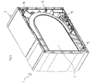
- a roller shutter box 1 has several profile parts 2, 3, 4, 5, which in the exemplary embodiment are an outer panel 2, a connecting panel 3, an inner panel 4 and a floor profile 5. These profile parts 2, 3, 4, 5 are PVC extruded profiles with hollow profiles that extend in the extrusion direction.
- the outer panel 2 is located after assembly on a window on the outside of a building, while the inner panel 4 is arranged inside the building.
- the connecting panel 3 closes the roller shutter box 1 at the top and the floor profile 5 at the bottom.
- the outer panel 2, the connecting panel 3, the inner panel 4 and the floor profile 5 together form a tubular device 6, which can be closed off at the side by a front hood 7 and a base 8 placed on it, thus forming a rolling space 17 inside.
- the roller shutter box 1 is usually closed on both sides by a front hood 7.
- the roller shutter box 1 is designed for connection to a window, which consists of a frame 20 and a sash frame 21, and a roller shutter curtain 18 which is guided in two roller shutter rails 19.
- the front hood 7 is essentially prism-shaped.
- the front hood 7 of the exemplary embodiment is cuboid in the broadest sense and has a base 8 and a lateral surface 9.
- the base 8 here has rounded corners and a rounded bulge on the top.
- the outer surface 9 of the front hood 7 extends at right angles to the base 8 and has essentially the same contour as the interior of the tube-like device 6.
- the front hoods 7 on both sides together with the tube-like device 6 form a closed roller shutter box 1 with internal rolling space 17 .
- the tube-like device 6 has on its inside on each profile part 2, 3, 4, 5 in each case at least one groove 10, which all extend in the extrusion direction of the profile parts 2, 3, 4, 5.
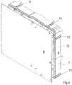
- the jacket surface 9 of the front hood 7 has several tongues 11 which correspond to the grooves 10 and engage in them.
- the grooves 10 and springs 11 are clip grooves 10 and clip springs 11.
- the clip grooves 10 are essentially grooves with an elliptical cross section and an extension of slightly over 180 °, so that the clip springs 11 with something Force and the resulting elastic deformation can be introduced and then go back elastically to their original shape, whereby the clip springs 11 remain in the clip grooves 10 and can only be pulled out by applying force and the resulting elastic deformation.
- a circumferential, molded-on foam seal 12 is arranged on the jacket surface 9 of the front hood 7. As a result, the roller shutter box 1 is sealed to the outside and does not rattle when exposed to dynamic loads, such as, for example, wind.
- Spreading devices 15 are provided on the jacket surface 9 of the front hood 7 (see FIG Figure 4 ). Screws can be inserted into these so that the spreading devices 15 are expanded. As a result, the front hood 7 is clamped to the tubular device 6 and the roller shutter box can be transported with vertical front hoods 7, for example, without the front hood 7 being displaced.
- FIG. 5 shows that the front hood 7 is connected with detachable means for mounting a shaft in the form of a slide 14 with stud bolts 16.
- the rotatable mounting of a roller shutter curtain is connected to the stud bolt 16.
- a plug-in inlet funnel 13 is connected to the front hood 7 for guiding a roller shutter curtain.
- an outer panel 2, a connecting panel 3, an inner panel 4 and a floor profile 5 are first cut to the desired length.
- the connecting panel 3 with its two clip grooves 10 is connected at both ends to the two corresponding clip springs 11 each with a front hood 7, the two front hoods 7 being arranged in such a way that the opening for the slide 14 points inward.
- the inner panel 4 is then articulated to the connecting panel 3 and placed on the front hoods 7 by means of a rotary movement, the clip groove 10 of the connecting panel 3 ultimately locking with the clip springs 11 of the two front hoods 7.
- the floor profile 5 is then articulated to the inner panel 4 and placed on the front hoods 7 by means of a rotary movement, the clip groove 10 of the floor profile 5 ultimately locking with the clip springs 11 of the two front hoods 7.
- Two slides 14 are positioned in such a way that the stud bolts 16 are each directed inward.
- a roller shutter curtain 18 is placed on the stud bolts 16 with a roller.
- a corresponding, plug-in inlet funnel 13 is connected to the front hoods 7. This connection is then pushed via the slide 14 into the receptacles provided for this purpose in the front hoods 7 in the rolling space 17.
- the roller shutter box 1 is then closed by locking the outer panel 2 with the connecting panel 3 and placing it on the front hoods 7 via a rotary movement and connecting it to the corresponding clip springs 11 of the two front hoods 7 via the clip groove 10 of the outer panel 2.
- screws are screwed into the spreading devices 15 of the front hood 7, whereby the front hoods 7 are immovably connected to the profile parts 2, 3, 4, 5.
- the roller shutter box 1 can now be installed.
- the invention is not limited to the exemplary embodiment.
Landscapes
- Engineering & Computer Science (AREA)
- Structural Engineering (AREA)
- Architecture (AREA)
- Civil Engineering (AREA)
- Operating, Guiding And Securing Of Roll- Type Closing Members (AREA)
Priority Applications (3)
| Application Number | Priority Date | Filing Date | Title |
|---|---|---|---|
| EP19210017.0A EP3825505A1 (fr) | 2019-11-19 | 2019-11-19 | Coffre de volet roulant pourvu d'une joue |
| ES20207158T ES2964708T3 (es) | 2019-11-19 | 2020-11-12 | Caja de persiana enrollable con cubierta frontal |
| EP20207158.5A EP3825506B1 (fr) | 2019-11-19 | 2020-11-12 | Coffre de volet roulant pourvu d'une joue |
Applications Claiming Priority (1)
| Application Number | Priority Date | Filing Date | Title |
|---|---|---|---|
| EP19210017.0A EP3825505A1 (fr) | 2019-11-19 | 2019-11-19 | Coffre de volet roulant pourvu d'une joue |
Publications (1)
| Publication Number | Publication Date |
|---|---|
| EP3825505A1 true EP3825505A1 (fr) | 2021-05-26 |
Family
ID=68731658
Family Applications (2)
| Application Number | Title | Priority Date | Filing Date |
|---|---|---|---|
| EP19210017.0A Withdrawn EP3825505A1 (fr) | 2019-11-19 | 2019-11-19 | Coffre de volet roulant pourvu d'une joue |
| EP20207158.5A Active EP3825506B1 (fr) | 2019-11-19 | 2020-11-12 | Coffre de volet roulant pourvu d'une joue |
Family Applications After (1)
| Application Number | Title | Priority Date | Filing Date |
|---|---|---|---|
| EP20207158.5A Active EP3825506B1 (fr) | 2019-11-19 | 2020-11-12 | Coffre de volet roulant pourvu d'une joue |
Country Status (2)
| Country | Link |
|---|---|
| EP (2) | EP3825505A1 (fr) |
| ES (1) | ES2964708T3 (fr) |
Families Citing this family (1)
| Publication number | Priority date | Publication date | Assignee | Title |
|---|---|---|---|---|
| FR3165462A1 (fr) * | 2024-08-07 | 2026-02-13 | Futurol | Dispositif de verrouillage pour un coffre de volet roulant |
Citations (7)
| Publication number | Priority date | Publication date | Assignee | Title |
|---|---|---|---|---|
| DE4405191A1 (de) * | 1994-02-18 | 1995-08-24 | Armin Besler | Rolladenkasten |
| DE29806186U1 (de) | 1997-04-03 | 1998-10-08 | Zurfluh Feller, Roide | Vorrichtung zur Montage eines Rolladenmechanismus |
| DE102005029578A1 (de) * | 2005-06-25 | 2007-01-11 | Thyssen Polymer Gmbh | Rollladenkasten |
| DE102009000643A1 (de) | 2008-02-05 | 2009-08-06 | Profine Gmbh | Profilsystem für einen Kunststoff-Rollladenkasten |
| DE102010001674A1 (de) | 2009-02-08 | 2010-08-19 | Profine Gmbh | Bauteilgruppe für einen Kunststoff-Rolladenkasten |
| EP2910725A1 (fr) * | 2014-02-19 | 2015-08-26 | Deprat Jean SA | Caisson pour un moyen roulant d'occultation |
| DE102010000153B4 (de) | 2010-01-21 | 2019-02-14 | Exte-Extrudertechnik Gmbh | Rollladenkasten |
-
2019
- 2019-11-19 EP EP19210017.0A patent/EP3825505A1/fr not_active Withdrawn
-
2020
- 2020-11-12 ES ES20207158T patent/ES2964708T3/es active Active
- 2020-11-12 EP EP20207158.5A patent/EP3825506B1/fr active Active
Patent Citations (7)
| Publication number | Priority date | Publication date | Assignee | Title |
|---|---|---|---|---|
| DE4405191A1 (de) * | 1994-02-18 | 1995-08-24 | Armin Besler | Rolladenkasten |
| DE29806186U1 (de) | 1997-04-03 | 1998-10-08 | Zurfluh Feller, Roide | Vorrichtung zur Montage eines Rolladenmechanismus |
| DE102005029578A1 (de) * | 2005-06-25 | 2007-01-11 | Thyssen Polymer Gmbh | Rollladenkasten |
| DE102009000643A1 (de) | 2008-02-05 | 2009-08-06 | Profine Gmbh | Profilsystem für einen Kunststoff-Rollladenkasten |
| DE102010001674A1 (de) | 2009-02-08 | 2010-08-19 | Profine Gmbh | Bauteilgruppe für einen Kunststoff-Rolladenkasten |
| DE102010000153B4 (de) | 2010-01-21 | 2019-02-14 | Exte-Extrudertechnik Gmbh | Rollladenkasten |
| EP2910725A1 (fr) * | 2014-02-19 | 2015-08-26 | Deprat Jean SA | Caisson pour un moyen roulant d'occultation |
Also Published As
| Publication number | Publication date |
|---|---|
| EP3825506C0 (fr) | 2023-09-06 |
| EP3825506B1 (fr) | 2023-09-06 |
| EP3825506A1 (fr) | 2021-05-26 |
| ES2964708T3 (es) | 2024-04-09 |
Similar Documents
| Publication | Publication Date | Title |
|---|---|---|
| DE102013224658B4 (de) | Spannrahmen für ein Insektenschutzgitter oder dergleichen netzartiges Gewebe | |
| EP3622149B1 (fr) | Rail de guidage d'un chariot d'une porte de meuble | |
| EP3001931B1 (fr) | Dispositif de recouvrement d'obturateur | |
| WO2011128167A1 (fr) | Partie boîtier pour une armoire de commande | |
| EP3825506B1 (fr) | Coffre de volet roulant pourvu d'une joue | |
| EP3071896A1 (fr) | Dispositif de retenue pour boîtier et procédé de montage du boîtier à l'aide du dispositif de retenue | |
| DE202016106504U1 (de) | Montagewerkzeug für die Montage einer Schaltschranktür an einem Schaltschrankgehäuse und eine entsprechende Schaltschrankanordnung | |
| EP3786405A1 (fr) | Entraînement de meuble permettant de déplacer un élément de meuble monté mobile | |
| DE102016005650A1 (de) | Schutzschrank | |
| EP3095365A1 (fr) | Separation de douche dotee d'une porte coulissante et element de guidage | |
| DE10116322C2 (de) | Verbindungselement für Profilleisten sowie daraus hergestellte Rahmenanordnung für den Trockenbau | |
| DE102016218262B4 (de) | Dachfenster | |
| DE202014103071U1 (de) | Rollladenkasten | |
| DE202013103663U1 (de) | Einbaurahmen für Schiebetüren | |
| DE102012100153A1 (de) | Seitenführung für Rollläden und Jalousien | |
| EP3530861A1 (fr) | Élément horizontal de cadre pour un cadre de porte coulissante et / ou de fenêtre coulissante, cadre de porte coulissante et / ou de fenêtre coulissante ainsi que système de porte coulissante et / ou de fenêtre coulissante | |
| EP2784262B1 (fr) | Armoire avec volet roulant | |
| EP4007097B1 (fr) | Composant d'installation souterraine | |
| DE102008025281B4 (de) | Führungsschiene eines Seilzug-Fensterhebers mit zugehöriger Schlauchfassung | |
| WO2003087508A1 (fr) | Dispositif d'accouplement | |
| DE4212227A1 (de) | Als Übergangsschutz zwischen zwei gelenkig miteinander gekuppelten Fahrzeugen einbaubarer Faltenbalg | |
| DE202008010542U1 (de) | Profilleistenvorrichtung | |
| DE2433720A1 (de) | Eingangs- oder durchgangstuer, insbesondere fuer duschenabtrennungen | |
| DE7817731U1 (de) | Torantrieb, insbesondere fuer garagentore, mit einem elektrischen antriebsmotor | |
| DE102015116641A1 (de) | Gebäudeabschlussantriebsvorrichtung |
Legal Events
| Date | Code | Title | Description |
|---|---|---|---|
| PUAI | Public reference made under article 153(3) epc to a published international application that has entered the european phase |
Free format text: ORIGINAL CODE: 0009012 |
|
| STAA | Information on the status of an ep patent application or granted ep patent |
Free format text: STATUS: THE APPLICATION HAS BEEN PUBLISHED |
|
| AK | Designated contracting states |
Kind code of ref document: A1 Designated state(s): AL AT BE BG CH CY CZ DE DK EE ES FI FR GB GR HR HU IE IS IT LI LT LU LV MC MK MT NL NO PL PT RO RS SE SI SK SM TR |
|
| RAP3 | Party data changed (applicant data changed or rights of an application transferred) |
Owner name: PROFINE GMBH |
|
| STAA | Information on the status of an ep patent application or granted ep patent |
Free format text: STATUS: THE APPLICATION IS DEEMED TO BE WITHDRAWN |
|
| 18D | Application deemed to be withdrawn |
Effective date: 20211127 |