EP3825532A1 - Getriebearchitektur für einen gasturbinenmotor - Google Patents
Getriebearchitektur für einen gasturbinenmotor Download PDFInfo
- Publication number
- EP3825532A1 EP3825532A1 EP20209057.7A EP20209057A EP3825532A1 EP 3825532 A1 EP3825532 A1 EP 3825532A1 EP 20209057 A EP20209057 A EP 20209057A EP 3825532 A1 EP3825532 A1 EP 3825532A1
- Authority
- EP
- European Patent Office
- Prior art keywords
- carrier
- ring gear
- bearing flange
- bearing
- sun gear
- Prior art date
- Legal status (The legal status is an assumption and is not a legal conclusion. Google has not performed a legal analysis and makes no representation as to the accuracy of the status listed.)
- Granted
Links
Images


Classifications
-
- F—MECHANICAL ENGINEERING; LIGHTING; HEATING; WEAPONS; BLASTING
- F16—ENGINEERING ELEMENTS AND UNITS; GENERAL MEASURES FOR PRODUCING AND MAINTAINING EFFECTIVE FUNCTIONING OF MACHINES OR INSTALLATIONS; THERMAL INSULATION IN GENERAL
- F16H—GEARING
- F16H57/00—General details of gearing
- F16H57/08—General details of gearing of gearings with members having orbital motion
- F16H57/082—Planet carriers
-
- F—MECHANICAL ENGINEERING; LIGHTING; HEATING; WEAPONS; BLASTING
- F02—COMBUSTION ENGINES; HOT-GAS OR COMBUSTION-PRODUCT ENGINE PLANTS
- F02C—GAS-TURBINE PLANTS; AIR INTAKES FOR JET-PROPULSION PLANTS; CONTROLLING FUEL SUPPLY IN AIR-BREATHING JET-PROPULSION PLANTS
- F02C7/00—Features, components parts, details or accessories, not provided for in, or of interest apart form groups F02C1/00 - F02C6/00; Air intakes for jet-propulsion plants
- F02C7/06—Arrangements of bearings; Lubricating
-
- F—MECHANICAL ENGINEERING; LIGHTING; HEATING; WEAPONS; BLASTING
- F02—COMBUSTION ENGINES; HOT-GAS OR COMBUSTION-PRODUCT ENGINE PLANTS
- F02C—GAS-TURBINE PLANTS; AIR INTAKES FOR JET-PROPULSION PLANTS; CONTROLLING FUEL SUPPLY IN AIR-BREATHING JET-PROPULSION PLANTS
- F02C7/00—Features, components parts, details or accessories, not provided for in, or of interest apart form groups F02C1/00 - F02C6/00; Air intakes for jet-propulsion plants
- F02C7/36—Power transmission arrangements between the different shafts of the gas turbine plant, or between the gas-turbine plant and the power user
-
- F—MECHANICAL ENGINEERING; LIGHTING; HEATING; WEAPONS; BLASTING
- F02—COMBUSTION ENGINES; HOT-GAS OR COMBUSTION-PRODUCT ENGINE PLANTS
- F02K—JET-PROPULSION PLANTS
- F02K3/00—Plants including a gas turbine driving a compressor or a ducted fan
- F02K3/02—Plants including a gas turbine driving a compressor or a ducted fan in which part of the working fluid by-passes the turbine and combustion chamber
- F02K3/04—Plants including a gas turbine driving a compressor or a ducted fan in which part of the working fluid by-passes the turbine and combustion chamber the plant including ducted fans, i.e. fans with high volume, low pressure outputs, for augmenting the jet thrust, e.g. of double-flow type
- F02K3/06—Plants including a gas turbine driving a compressor or a ducted fan in which part of the working fluid by-passes the turbine and combustion chamber the plant including ducted fans, i.e. fans with high volume, low pressure outputs, for augmenting the jet thrust, e.g. of double-flow type with front fan
-
- F—MECHANICAL ENGINEERING; LIGHTING; HEATING; WEAPONS; BLASTING
- F16—ENGINEERING ELEMENTS AND UNITS; GENERAL MEASURES FOR PRODUCING AND MAINTAINING EFFECTIVE FUNCTIONING OF MACHINES OR INSTALLATIONS; THERMAL INSULATION IN GENERAL
- F16C—SHAFTS; FLEXIBLE SHAFTS; ELEMENTS OR CRANKSHAFT MECHANISMS; ROTARY BODIES OTHER THAN GEARING ELEMENTS; BEARINGS
- F16C33/00—Parts of bearings; Special methods for making bearings or parts thereof
- F16C33/30—Parts of ball or roller bearings
- F16C33/58—Raceways; Race rings
- F16C33/60—Raceways; Race rings divided or split, e.g. comprising two juxtaposed rings
- F16C33/605—Raceways; Race rings divided or split, e.g. comprising two juxtaposed rings with a separate retaining member, e.g. flange, shoulder, guide ring, secured to a race ring, adjacent to the race surface, so as to abut the end of the rolling elements, e.g. rollers, or the cage
-
- F—MECHANICAL ENGINEERING; LIGHTING; HEATING; WEAPONS; BLASTING
- F05—INDEXING SCHEMES RELATING TO ENGINES OR PUMPS IN VARIOUS SUBCLASSES OF CLASSES F01-F04
- F05D—INDEXING SCHEME FOR ASPECTS RELATING TO NON-POSITIVE-DISPLACEMENT MACHINES OR ENGINES, GAS-TURBINES OR JET-PROPULSION PLANTS
- F05D2260/00—Function
- F05D2260/40—Transmission of power
- F05D2260/403—Transmission of power through the shape of the drive components
- F05D2260/4031—Transmission of power through the shape of the drive components as in toothed gearing
- F05D2260/40311—Transmission of power through the shape of the drive components as in toothed gearing of the epicyclical, planetary or differential type
-
- F—MECHANICAL ENGINEERING; LIGHTING; HEATING; WEAPONS; BLASTING
- F16—ENGINEERING ELEMENTS AND UNITS; GENERAL MEASURES FOR PRODUCING AND MAINTAINING EFFECTIVE FUNCTIONING OF MACHINES OR INSTALLATIONS; THERMAL INSULATION IN GENERAL
- F16H—GEARING
- F16H57/00—General details of gearing
- F16H57/08—General details of gearing of gearings with members having orbital motion
- F16H2057/085—Bearings for orbital gears
Definitions
- a gas turbine engine typically includes a fan section, a compressor section, a combustor section, and a turbine section. Air entering the compressor section is compressed and delivered into the combustion section where it is mixed with fuel and ignited to generate a high-speed exhaust gas flow. The high-speed exhaust gas flow expands through the turbine section to drive the compressor and the fan section.
- a fan drive turbine has driven the fan directly on a common spool and at a single speed. More recently, a gear reduction has been placed between the fan and the fan drive turbine. This allows the fan to rotate at slower speeds than the fan drive turbine.
- a turbofan engine in one aspect, includes a fan section.
- a turbine section is in driving engagement with the fan section through a star gear system.
- the star gear system includes a plurality of star gears surrounding a sun gear.
- a carrier supports the plurality of star gears and includes a first carrier bearing flange.
- a ring gear surrounds the plurality of star gears and includes a ring gear bearing flange. At least one ring gear carrier bearing engages the carrier bearing flange and the ring gear bearing flange.
- the carrier is fixed from rotation relative to an engine static structure by a rigid support.
- a flexible output shaft is in driving engagement with the output shaft (or a fan drive shaft).
- a flexible input shaft is in driving engagement with the sun gear.
- the at least one ring gear carrier bearing includes at least one inner race that engages a radially outer side of the ring gear bearing flange and an outer race that engages a radially inner side of the carrier bearing flange.
- the ring gear includes an axially forward extending portion extending forward of a forward plate of the carrier and a radially inward extending portion having the ring gear bearing flange.
- the ring gear bearing flange extends axially downstream from the radially inward extending portion of the ring gear.
- the carrier includes a second carrier bearing flange on an aft plate of the carrier and at least one carrier sun gear bearing (or sun gear carrier bearing) engages the second carrier bearing flange and an axially aft bearing flange on the sun gear.
- the sun gear includes an axially forward bearing flange and at least one ring gear carrier bearing engaging the ring gear bearing flange and the axially forward bearing flange on the sun gear.
- the ring gear includes an axially aft extending bearing flange and the at least one ring gear bearing includes a second ring gear bearing engaging the axially aft extending bearing flange and the aft plate of the carrier.
- the carrier includes a second carrier bearing flange on an aft plate of the carrier and at least one carrier sun gear bearing (or sun gear carrier bearing) engages the second carrier bearing flange and an axially aft bearing flange on the sun gear.
- a speed change mechanism for a gas turbine engine that includes a plurality of star gears surrounding a sun gear.
- a carrier supports the plurality of star gears and including a first carrier bearing flange.
- a ring gear surrounds the plurality of star gears and including a ring gear bearing flange. At least one ring gear carrier bearing engages the carrier bearing flange and the ring gear bearing flange.
- the at least one ring gear carrier bearing includes at least one inner race that engages a radially outer side of the ring gear bearing flange and an outer race that engages a radially inner side of the carrier bearing flange.
- the ring gear includes an axially forward extending portion extending forward of a forward plate of the carrier and a radially inward extending portion having the ring gear bearing flange.
- the ring gear bearing flange extends axially downstream from the radially inward extending portion of the ring gear.
- the carrier includes a second carrier bearing flange on an aft plate of the carrier and at least one sun gear carrier bearing engages the second carrier bearing flange and an axially aft bearing flange on the sun gear.
- the sun gear includes an axially forward bearing flange and at least one sun gear carrier bearing engaging the ring gear bearing flange and the axially forward bearing flange on the sun gear.
- the axially forward bearing flange on the sun gear is at least partially axially aligned with the first carrier bearing flange.
- the ring gear includes an axially aft extending bearing flange and the at least one ring gear bearing includes a second ring gear bearing engaging the axially aft extending bearing flange and the aft plate of the carrier.
- the carrier includes a second carrier bearing flange on an aft plate of the carrier and at least one sun gear carrier bearing engages the second carrier bearing flange and an axially aft bearing flange on the sun gear.
- FIG. 1 schematically illustrates a gas turbine engine 20.
- the gas turbine engine 20 is disclosed herein as a two-spool turbofan that generally incorporates a fan section 22, a compressor section 24, a combustor section 26 and a turbine section 28.
- the fan section 22 drives air along a bypass flow path B in a bypass duct defined within a housing 15, such as a fan case or nacelle, and also drives air along a core flow path C for compression and communication into the combustor section 26 then expansion through the turbine section 28.
- the exemplary engine 20 generally includes a low speed spool 30 and a high speed spool 32 mounted for rotation about an engine central longitudinal axis A relative to an engine static structure 36 via several bearing systems 38. It should be understood that various bearing systems 38 at various locations may alternatively or additionally be provided, and the location of bearing systems 38 may be varied as appropriate to the application.
- the low speed spool 30 generally includes an inner shaft 40 that interconnects, a first (or low) pressure compressor 44 and a first (or low) pressure turbine 46.
- the inner shaft 40 is connected to the fan 42 through a speed change mechanism, which in exemplary gas turbine engine 20 is illustrated as a geared architecture 48 to drive a fan 42 at a lower speed than the low speed spool 30.
- the high speed spool 32 includes an outer shaft 50 that interconnects a second (or high) pressure compressor 52 and a second (or high) pressure turbine 54.
- a combustor 56 is arranged in exemplary gas turbine 20 between the high pressure compressor 52 and the high pressure turbine 54.
- a mid-turbine frame 57 of the engine static structure 36 may be arranged generally between the high pressure turbine 54 and the low pressure turbine 46.
- the mid-turbine frame 57 further supports bearing systems 38 in the turbine section 28.
- the inner shaft 40 and the outer shaft 50 are concentric and rotate via bearing systems 38 about the engine central longitudinal axis A which is colline
- the core airflow is compressed by the low pressure compressor 44 then the high pressure compressor 52, mixed and burned with fuel in the combustor 56, then expanded over the high pressure turbine 54 and low pressure turbine 46.
- the mid-turbine frame 57 includes airfoils 59 which are in the core airflow path C.
- the turbines 46, 54 rotationally drive the respective low speed spool 30 and high speed spool 32 in response to the expansion.
- gear system 48 may be located aft of the low pressure compressor, or aft of the combustor section 26 or even aft of turbine section 28, and fan 42 may be positioned forward or aft of the location of gear system 48.
- the engine 20 in one example is a high-bypass geared aircraft engine.
- the engine 20 bypass ratio is greater than about six, with an example embodiment being greater than about ten
- the geared architecture 48 is an epicyclic gear train, such as a planetary gear system or other gear system, with a gear reduction ratio of greater than about 2.3 and the low pressure turbine 46 has a pressure ratio that is greater than about five.
- the engine 20 bypass ratio is greater than about ten
- the fan diameter is significantly larger than that of the low pressure compressor 44
- the low pressure turbine 46 has a pressure ratio that is greater than about five.
- Low pressure turbine 46 pressure ratio is pressure measured prior to inlet of low pressure turbine 46 as related to the pressure at the outlet of the low pressure turbine 46 prior to an exhaust nozzle.
- the geared architecture 48 may be an epicycle gear train, such as a planetary gear system or other gear system, with a gear reduction ratio of greater than about 2.3:1 and less than about 5:1. It should be understood, however, that the above parameters are only exemplary of one embodiment of a geared architecture engine and that the present invention is applicable to other gas turbine engines including direct drive turbofans.
- the fan section 22 of the engine 20 is designed for a particular flight condition -- typically cruise at about 0.8 Mach and about 35,000 feet (10,668 meters).
- the flight condition of 0.8 Mach and 35,000 ft (10,668 meters), with the engine at its best fuel consumption - also known as "bucket cruise Thrust Specific Fuel Consumption ('TSFC')" - is the industry standard parameter of lbm of fuel being burned divided by lbf of thrust the engine produces at that minimum point.
- "Low fan pressure ratio” is the pressure ratio across the fan blade alone, without a Fan Exit Guide Vane (“FEGV”) system.
- the low fan pressure ratio as disclosed herein according to one non-limiting embodiment is less than about 1.45.
- the "Low corrected fan tip speed” as disclosed herein according to one non-limiting embodiment is less than about 1150 ft / second (350.5 meters/second).
- Figure 2 illustrates an enlarged view of the geared architecture 48.
- the inner shaft 40 drives a flexible input shaft 70 having a plurality of undulations 72, which contribute to the flexibility of the input shaft 70.
- the inner shaft 40 also drives the low pressure compressor 44 at the same rotational speed as the flexible input shaft 70 such that the low pressure compressor 44 rotates at a higher rotational speed than the fan 42.
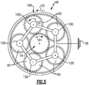
- Figure 5 shows a cross-sectional view of Figure 2 through geared architecture 48.
- the geared architecture 48 can include a sun gear 74, a carrier 90 supporting star gears 82, and a ring gear 108.
- the sun gear 74 is driven by the flexible input shaft 70.
- the sun gear 74 includes a first set of sun gear teeth 76 located axially forward of a second set of sun gear teeth 78 that are separated by a sun gear trough 80.
- multiple star gears 82 are circumferentially spaced around the sun gear 74 and include a first set of star gear teeth 84 located axially forward of a second set of star gear teeth 86 that are separated by a star gear trough 88.
- the first and second set of sun gear teeth 76, 78 engage a corresponding one of the first and second set of star gear teeth 84, 86, respectively.
- axial or axially and radial or radially is in relation to the engine axis A unless stated otherwise. Additionally, upstream and downstream and forward and aft are in relation to a direction of airflow through the engine 20.
- the carrier 90 includes a forward plate 92 fixed relative to an aft plate 94. Both the forward and aft plates 92, 94 are fixed from rotating relative to the engine static structure 36 by a carrier support 96 engaging the aft carrier plate 94 and a portion of the engine static structure 36.
- the carrier support 96 is flexible and includes at least one undulation that contributes to the flexibility of the carrier support 96.
- the forward and aft plates 92, 94 support star gear shafts 98 that are fixed relative to the forward and aft plates 92, 94.
- Star gear bearings 100 include an inner race 102 that is fixed relative to the star gear shafts 98 and an outer race 104 that is fixed relative to the star gears 82 and rotates with the star gears 82.
- the star gear bearings 100 are shown as ball bearings, other types of bearings such as roller bearings or journal bearings could be used to support the star gears 82.
- the ring gear 108 is located radially outward from the star gears 82 and includes a forward set of ring gear teeth 110 located axially forward of an aft set of ring gear teeth 112 that are separated by a ring gear trough 114.
- the forward and aft sets of ring gear teeth 110, 112 engage the forward and aft set of star gear teeth 84, 86, respectively.
- the ring gear 108 also includes a forward extending projection 116 that extends axially forward until it reaches a radially extending projection 118 that extends radially inward toward a flexible output shaft 120.
- the flexible output shaft 120 includes multiple undulations 122 that contribute to the flexibility of the flexible output shaft 120 while still allowing the flexible output shaft 120 to transmit torque and rotational forces.
- the fan 42 is supported for rotation about the engine axis A by a fan drive shaft 121 with fan shaft bearings 123 engaging the fan drive shaft 121 on a radially inner side and the engine static structure 36 on a radially outer side.
- the flexible output shaft 120 is located radially inward from the fan drive shaft 121 and engages the fan drive shaft 121 axially forward of the fan shaft bearings 123.
- One feature of this configuration is an increased axial length of the flexible output shaft 120 to allow for greater flexibility and a more axially compact design of the gas turbine engine 20 because the fan drive shaft 121 and the flexible output shaft 120 overlap axially.
- a ring gear aft extending bearing flange 124 extends axially downstream or aft from the radially extending projection 118.
- the bearing flange 124 includes a radially outer surface 126 having a generally constant radial dimension.
- the bearing flange 124 is at least partially axially aligned with a forward extending bearing flange 128 extending axially forward from the forward plate 92 of the carrier 90.
- a pair of ring gear carrier bearings 130 each include an inner race 132 that rotates with the ring gear 108 and the flexible output shaft 120 and an outer race 134 that is fixed relative to the forward plate 92 of the carrier 90.
- ring gear carrier bearings 130 each engaging one of the bearing flange 124 and the bearing flange 128 and the bearings 130 are ball bearings.
- other types of bearings such as roller bearings, could be used and more than two ring gear carrier bearings 130 could be used or only one ring gear carrier bearing 130 could be used in the illustrated location.
- the aft carrier plate 94 includes an aft extending bearing flange 136
- the sun gear includes an aft bearing flange 137
- a pair of sun gear carrier bearings 138 engaging both the bearing flanges 136, 137.
- Each of the sun gear carrier bearings 138 include an inner race 140 fixed to rotate with the sun gear 74 and an outer race 142 fixed relative to the bearing flange 136.
- the sun gear carrier bearings 138 are ball bearings. However, other types of bearings, such as roller bearings, could be used and more than two sun gear carrier bearings 138 could be used or only one sun gear carrier bearing 138 could be used in the illustrated location.
- One feature associated with utilizing at least one of the ring gear carrier bearings 130 and at least one of the sun gear carrier bearings 138 is the ability to maintain the sun gear 74, the star gears 82, and the ring gear 108 aligned and concentric. This reduces stress in the components that can result from misalignment.
- This arrangement further accomplishes the above feature by maintaining the sun gear 74, the star gears 82, and the ring gear 108 in a rigid arrangement through the use of the ring gear carrier bearings 130 and sun gear carrier bearings 138.
- the static nature of the geared architecture 48 is further accomplished with the carrier 92 attached to the engine static structure 36 though the rigid carrier support 96 as opposed to a flexible support that would allow for greater movement of the geared architecture 48. Additionally, the flexible input shaft 70 and the flexible output shaft 120 allow forces from the fan 42 and inner shaft 40 to have little if any influence on alignment of the sun gear 74, star gears 82, and ring gear 108.
- Figure 3 illustrates another example geared architecture 148 similar to the geared architecture 48 except where described below or shown in the Figures. Like numbers will be used between similar or identical components between the geared architecture 48 and the geared architecture 148.
- the geared architecture 148 includes the sun gear carrier bearings 138 located on an axially forward or upstream side of the geared architecture 148 as opposed to being located on an axially aft or downstream side as shown with the geared architecture 48.
- the inner race 140 rotates with the sun gear 74 and engages a sun gear forward bearing flange 173.
- the forward bearing flange 173 extends from an axially forward side of the sun gear 74 and includes a bearing contact surface 175 on a radially outer side.
- the outer race 142 on the sun gear carrier bearings 138 engages a radially inner side of the bearing flange 124 such that the outer race 142 rotates with the output shaft.
- Figure 4 illustrates another example geared architecture 248 similar to the geared architectures 48, 148 except where described below or shown in the Figures. Like numbers will be used between similar or identical components between the geared architectures 48, 148 and the geared architecture 248.
- the geared architecture 248 incudes one of the sun gear carrier bearings 138 located on a forward side similar to the geared architecture 48 and one of the sun gear carrier bearings 138 located on an aft side similar to the geared architecture 48. Additionally, one of the ring gear carrier bearings 130 is also located on the aft side of the geared architecture 248 as well as on a forward side of the geared architecture 248. When at least one of the ring gear carrier bearings 130 is located on a forward side of the geared architecture 248, it is positioned similar to the ring gear carrier bearing 130 shown in the geared architectures 48, 148.
- the at least one of the ring gear carrier bearings 130 is located between an aft ring gear projection 109 and the aft plate 94 of the carrier 90.
- the aft ring gear projection 109 extends axially aft from a downstream side of the ring gear 108 and is located radially outward from the first and second sets of ring gear teeth 110, 112.
- the ring gear carrier bearing 130 engages a radially outer edge of the aft carrier plate 94.
- the ring gear carrier bearing 130 could engage another portion of the aft plate 94 on the carrier 90.
- the carrier support 96 engages the aft plate 94 of the carrier 90 radially inward of the ring gear carrier bearing 130 in the illustrated example.
Landscapes
- Engineering & Computer Science (AREA)
- General Engineering & Computer Science (AREA)
- Chemical & Material Sciences (AREA)
- Combustion & Propulsion (AREA)
- Mechanical Engineering (AREA)
- Retarders (AREA)
Applications Claiming Priority (1)
| Application Number | Priority Date | Filing Date | Title |
|---|---|---|---|
| US16/689,695 US11162575B2 (en) | 2019-11-20 | 2019-11-20 | Geared architecture for gas turbine engine |
Publications (2)
| Publication Number | Publication Date |
|---|---|
| EP3825532A1 true EP3825532A1 (de) | 2021-05-26 |
| EP3825532B1 EP3825532B1 (de) | 2025-06-04 |
Family
ID=73543202
Family Applications (1)
| Application Number | Title | Priority Date | Filing Date |
|---|---|---|---|
| EP20209057.7A Active EP3825532B1 (de) | 2019-11-20 | 2020-11-20 | Getriebearchitektur für einen gasturbinenmotor |
Country Status (2)
| Country | Link |
|---|---|
| US (1) | US11162575B2 (de) |
| EP (1) | EP3825532B1 (de) |
Cited By (1)
| Publication number | Priority date | Publication date | Assignee | Title |
|---|---|---|---|---|
| US12055059B2 (en) | 2021-12-10 | 2024-08-06 | General Electric Company | Windage cover that covers fasteners coupling a ring gear assembly to an output shaft |
Families Citing this family (3)
| Publication number | Priority date | Publication date | Assignee | Title |
|---|---|---|---|---|
| US11215122B2 (en) * | 2019-11-20 | 2022-01-04 | Raytheon Technologies Corporation | Geared architecture for gas turbine engine |
| FR3134867B1 (fr) * | 2022-04-22 | 2024-05-17 | Safran Trans Systems | Reducteur mecanique de turbomachine d’aeronef |
| US12331683B2 (en) * | 2023-09-29 | 2025-06-17 | Rtx Corporation | Bearing arrangement for turbine engine geartrain |
Citations (4)
| Publication number | Priority date | Publication date | Assignee | Title |
|---|---|---|---|---|
| US20060059887A1 (en) * | 2004-09-03 | 2006-03-23 | Hermann Klingels | Aircraft engine with separate auxiliary rotor and fan rotor |
| WO2014047040A1 (en) * | 2012-09-20 | 2014-03-27 | United Technologies Corporation | Flexible support structure for a geared architecture gas turbine engine |
| EP3144486A1 (de) * | 2015-09-18 | 2017-03-22 | Rolls-Royce plc | Wellenanordnung für einen gasturbinenmotor |
| US20180010551A1 (en) * | 2016-07-11 | 2018-01-11 | United Technologies Corporation | Geared gas turbine engine |
Family Cites Families (22)
| Publication number | Priority date | Publication date | Assignee | Title |
|---|---|---|---|---|
| KR100851578B1 (ko) * | 2000-08-29 | 2008-08-12 | 가부시키카이샤 나브코 | 주행유닛 |
| US8585538B2 (en) | 2006-07-05 | 2013-11-19 | United Technologies Corporation | Coupling system for a star gear train in a gas turbine engine |
| US7704178B2 (en) | 2006-07-05 | 2010-04-27 | United Technologies Corporation | Oil baffle for gas turbine fan drive gear system |
| US7694505B2 (en) * | 2006-07-31 | 2010-04-13 | General Electric Company | Gas turbine engine assembly and method of assembling same |
| US8020665B2 (en) | 2006-11-22 | 2011-09-20 | United Technologies Corporation | Lubrication system with extended emergency operability |
| WO2011077869A1 (ja) * | 2009-12-21 | 2011-06-30 | 本田技研工業株式会社 | プラネタリギヤのピニオンシャフト支持構造 |
| US8572943B1 (en) | 2012-05-31 | 2013-11-05 | United Technologies Corporation | Fundamental gear system architecture |
| DE102012018714A1 (de) * | 2012-09-21 | 2014-03-27 | Robert Bosch Gmbh | Planetengetriebe |
| US9926850B2 (en) | 2013-02-11 | 2018-03-27 | United Technologies Corporation | Compound star gear system with rolling element bearings |
| US9863326B2 (en) | 2013-03-12 | 2018-01-09 | United Technologies Corporation | Flexible coupling for geared turbine engine |
| WO2014151176A1 (en) * | 2013-03-15 | 2014-09-25 | United Technologies Corporation | Turbofan engine main bearing arrangement |
| EP3004595B1 (de) * | 2013-06-03 | 2020-09-02 | United Technologies Corporation | Anordnung aus einem turbofan-triebwerklager und einem getriebe |
| US10280843B2 (en) * | 2014-03-07 | 2019-05-07 | United Technologies Corporation | Geared turbofan with integral front support and carrier |
| GB201417505D0 (en) | 2014-10-03 | 2014-11-19 | Rolls Royce Deutschland | A gas turbine architecture |
| GB201417504D0 (en) | 2014-10-03 | 2014-11-19 | Rolls Royce Deutschland | A gas turbine architecture |
| US11067005B2 (en) | 2015-02-03 | 2021-07-20 | Raytheon Technologies Corporation | Fan drive gear system |
| US10371244B2 (en) | 2015-04-09 | 2019-08-06 | United Technologies Corporation | Additive manufactured gear for a geared architecture gas turbine engine |
| GB201516571D0 (en) | 2015-09-18 | 2015-11-04 | Rolls Royce Plc | A Coupling for a Geared Turbo Fan |
| US10167929B2 (en) * | 2016-06-22 | 2019-01-01 | Nidec-Shimpo (Zhe Jiang) Corporation | Speed reducer and actuator |
| GB201613029D0 (en) | 2016-07-28 | 2016-09-14 | Rolls Royce Plc | A sun gear drive arrangement |
| US10669948B2 (en) | 2017-01-03 | 2020-06-02 | Raytheon Technologies Corporation | Geared turbofan with non-epicyclic gear reduction system |
| US11015533B2 (en) * | 2018-12-17 | 2021-05-25 | Raytheon Technologies Corporation | Fan and low pressure compressor geared to low speed spool of gas turbine engine |
-
2019
- 2019-11-20 US US16/689,695 patent/US11162575B2/en active Active
-
2020
- 2020-11-20 EP EP20209057.7A patent/EP3825532B1/de active Active
Patent Citations (4)
| Publication number | Priority date | Publication date | Assignee | Title |
|---|---|---|---|---|
| US20060059887A1 (en) * | 2004-09-03 | 2006-03-23 | Hermann Klingels | Aircraft engine with separate auxiliary rotor and fan rotor |
| WO2014047040A1 (en) * | 2012-09-20 | 2014-03-27 | United Technologies Corporation | Flexible support structure for a geared architecture gas turbine engine |
| EP3144486A1 (de) * | 2015-09-18 | 2017-03-22 | Rolls-Royce plc | Wellenanordnung für einen gasturbinenmotor |
| US20180010551A1 (en) * | 2016-07-11 | 2018-01-11 | United Technologies Corporation | Geared gas turbine engine |
Cited By (2)
| Publication number | Priority date | Publication date | Assignee | Title |
|---|---|---|---|---|
| US12055059B2 (en) | 2021-12-10 | 2024-08-06 | General Electric Company | Windage cover that covers fasteners coupling a ring gear assembly to an output shaft |
| US12378898B2 (en) | 2021-12-10 | 2025-08-05 | General Electric Company | Windage cover that covers fasteners coupling a ring gear assembly to an output shaft |
Also Published As
| Publication number | Publication date |
|---|---|
| US11162575B2 (en) | 2021-11-02 |
| EP3825532B1 (de) | 2025-06-04 |
| US20210148454A1 (en) | 2021-05-20 |
Similar Documents
| Publication | Publication Date | Title |
|---|---|---|
| US11566586B2 (en) | Gas turbine engine shaft bearing configuration | |
| US11927138B2 (en) | Fan drive gear system | |
| US11162430B2 (en) | Geared gas turbine engine | |
| EP3808964B1 (de) | Getriebefan mit einem nicht epizyklischen untersetzungssystem | |
| US11994074B2 (en) | Fan drive gear system | |
| EP3825532B1 (de) | Getriebearchitektur für einen gasturbinenmotor | |
| EP3097275B1 (de) | Flexible trägerstruktur für einen gasturbinenmotor mit getriebearchitektur | |
| US20160084104A1 (en) | Fan drive gear system | |
| US11415064B2 (en) | Geared architecture for gas turbine engine | |
| WO2015094539A1 (en) | Transfer bearing for geared turbofan | |
| EP3825575B1 (de) | Getriebearchitektur für einen gasturbinenmotor | |
| US11492932B2 (en) | Deflection limiter for a gas turbine engine | |
| US11035252B2 (en) | Unified curved beam bearing damper | |
| EP2899389A1 (de) | Flexible Trägerstruktur für Getriebearchitektur-Gasturbinenmotor | |
| EP3000989B1 (de) | Turbofan-getriebesystem | |
| EP4170143A1 (de) | Im grätschsitz montierter niederdruckverdichter | |
| EP3626935B1 (de) | Ein drehzahländerungsmechanismus für ein gasturbinentriebwerk |
Legal Events
| Date | Code | Title | Description |
|---|---|---|---|
| PUAI | Public reference made under article 153(3) epc to a published international application that has entered the european phase |
Free format text: ORIGINAL CODE: 0009012 |
|
| STAA | Information on the status of an ep patent application or granted ep patent |
Free format text: STATUS: THE APPLICATION HAS BEEN PUBLISHED |
|
| AK | Designated contracting states |
Kind code of ref document: A1 Designated state(s): AL AT BE BG CH CY CZ DE DK EE ES FI FR GB GR HR HU IE IS IT LI LT LU LV MC MK MT NL NO PL PT RO RS SE SI SK SM TR |
|
| STAA | Information on the status of an ep patent application or granted ep patent |
Free format text: STATUS: REQUEST FOR EXAMINATION WAS MADE |
|
| 17P | Request for examination filed |
Effective date: 20211125 |
|
| RBV | Designated contracting states (corrected) |
Designated state(s): AL AT BE BG CH CY CZ DE DK EE ES FI FR GB GR HR HU IE IS IT LI LT LU LV MC MK MT NL NO PL PT RO RS SE SI SK SM TR |
|
| STAA | Information on the status of an ep patent application or granted ep patent |
Free format text: STATUS: EXAMINATION IS IN PROGRESS |
|
| 17Q | First examination report despatched |
Effective date: 20230329 |
|
| RAP3 | Party data changed (applicant data changed or rights of an application transferred) |
Owner name: RTX CORPORATION |
|
| GRAP | Despatch of communication of intention to grant a patent |
Free format text: ORIGINAL CODE: EPIDOSNIGR1 |
|
| STAA | Information on the status of an ep patent application or granted ep patent |
Free format text: STATUS: GRANT OF PATENT IS INTENDED |
|
| INTG | Intention to grant announced |
Effective date: 20250130 |
|
| GRAS | Grant fee paid |
Free format text: ORIGINAL CODE: EPIDOSNIGR3 |
|
| GRAA | (expected) grant |
Free format text: ORIGINAL CODE: 0009210 |
|
| STAA | Information on the status of an ep patent application or granted ep patent |
Free format text: STATUS: THE PATENT HAS BEEN GRANTED |
|
| AK | Designated contracting states |
Kind code of ref document: B1 Designated state(s): AL AT BE BG CH CY CZ DE DK EE ES FI FR GB GR HR HU IE IS IT LI LT LU LV MC MK MT NL NO PL PT RO RS SE SI SK SM TR |
|
| REG | Reference to a national code |
Ref country code: GB Ref legal event code: FG4D |
|
| REG | Reference to a national code |
Ref country code: CH Ref legal event code: EP |
|
| REG | Reference to a national code |
Ref country code: DE Ref legal event code: R096 Ref document number: 602020052224 Country of ref document: DE |
|
| REG | Reference to a national code |
Ref country code: IE Ref legal event code: FG4D |
|
| REG | Reference to a national code |
Ref country code: NL Ref legal event code: MP Effective date: 20250604 |
|
| PG25 | Lapsed in a contracting state [announced via postgrant information from national office to epo] |
Ref country code: FI Free format text: LAPSE BECAUSE OF FAILURE TO SUBMIT A TRANSLATION OF THE DESCRIPTION OR TO PAY THE FEE WITHIN THE PRESCRIBED TIME-LIMIT Effective date: 20250604 Ref country code: ES Free format text: LAPSE BECAUSE OF FAILURE TO SUBMIT A TRANSLATION OF THE DESCRIPTION OR TO PAY THE FEE WITHIN THE PRESCRIBED TIME-LIMIT Effective date: 20250604 |
|
| REG | Reference to a national code |
Ref country code: LT Ref legal event code: MG9D |
|
| PG25 | Lapsed in a contracting state [announced via postgrant information from national office to epo] |
Ref country code: NO Free format text: LAPSE BECAUSE OF FAILURE TO SUBMIT A TRANSLATION OF THE DESCRIPTION OR TO PAY THE FEE WITHIN THE PRESCRIBED TIME-LIMIT Effective date: 20250904 Ref country code: GR Free format text: LAPSE BECAUSE OF FAILURE TO SUBMIT A TRANSLATION OF THE DESCRIPTION OR TO PAY THE FEE WITHIN THE PRESCRIBED TIME-LIMIT Effective date: 20250905 |
|
| PG25 | Lapsed in a contracting state [announced via postgrant information from national office to epo] |
Ref country code: PL Free format text: LAPSE BECAUSE OF FAILURE TO SUBMIT A TRANSLATION OF THE DESCRIPTION OR TO PAY THE FEE WITHIN THE PRESCRIBED TIME-LIMIT Effective date: 20250604 |
|
| PG25 | Lapsed in a contracting state [announced via postgrant information from national office to epo] |
Ref country code: BG Free format text: LAPSE BECAUSE OF FAILURE TO SUBMIT A TRANSLATION OF THE DESCRIPTION OR TO PAY THE FEE WITHIN THE PRESCRIBED TIME-LIMIT Effective date: 20250604 |
|
| PG25 | Lapsed in a contracting state [announced via postgrant information from national office to epo] |
Ref country code: HR Free format text: LAPSE BECAUSE OF FAILURE TO SUBMIT A TRANSLATION OF THE DESCRIPTION OR TO PAY THE FEE WITHIN THE PRESCRIBED TIME-LIMIT Effective date: 20250604 |
|
| PG25 | Lapsed in a contracting state [announced via postgrant information from national office to epo] |
Ref country code: RS Free format text: LAPSE BECAUSE OF FAILURE TO SUBMIT A TRANSLATION OF THE DESCRIPTION OR TO PAY THE FEE WITHIN THE PRESCRIBED TIME-LIMIT Effective date: 20250904 |
|
| PG25 | Lapsed in a contracting state [announced via postgrant information from national office to epo] |
Ref country code: LV Free format text: LAPSE BECAUSE OF FAILURE TO SUBMIT A TRANSLATION OF THE DESCRIPTION OR TO PAY THE FEE WITHIN THE PRESCRIBED TIME-LIMIT Effective date: 20250604 |
|
| PG25 | Lapsed in a contracting state [announced via postgrant information from national office to epo] |
Ref country code: NL Free format text: LAPSE BECAUSE OF FAILURE TO SUBMIT A TRANSLATION OF THE DESCRIPTION OR TO PAY THE FEE WITHIN THE PRESCRIBED TIME-LIMIT Effective date: 20250604 |
|
| PG25 | Lapsed in a contracting state [announced via postgrant information from national office to epo] |
Ref country code: PT Free format text: LAPSE BECAUSE OF FAILURE TO SUBMIT A TRANSLATION OF THE DESCRIPTION OR TO PAY THE FEE WITHIN THE PRESCRIBED TIME-LIMIT Effective date: 20251006 |
|
| REG | Reference to a national code |
Ref country code: AT Ref legal event code: MK05 Ref document number: 1800521 Country of ref document: AT Kind code of ref document: T Effective date: 20250604 |
|
| PG25 | Lapsed in a contracting state [announced via postgrant information from national office to epo] |
Ref country code: IS Free format text: LAPSE BECAUSE OF FAILURE TO SUBMIT A TRANSLATION OF THE DESCRIPTION OR TO PAY THE FEE WITHIN THE PRESCRIBED TIME-LIMIT Effective date: 20251004 |
|
| PGFP | Annual fee paid to national office [announced via postgrant information from national office to epo] |
Ref country code: DE Payment date: 20251022 Year of fee payment: 6 |
|
| PGFP | Annual fee paid to national office [announced via postgrant information from national office to epo] |
Ref country code: GB Payment date: 20251022 Year of fee payment: 6 |
|
| PG25 | Lapsed in a contracting state [announced via postgrant information from national office to epo] |
Ref country code: SM Free format text: LAPSE BECAUSE OF FAILURE TO SUBMIT A TRANSLATION OF THE DESCRIPTION OR TO PAY THE FEE WITHIN THE PRESCRIBED TIME-LIMIT Effective date: 20250604 Ref country code: AT Free format text: LAPSE BECAUSE OF FAILURE TO SUBMIT A TRANSLATION OF THE DESCRIPTION OR TO PAY THE FEE WITHIN THE PRESCRIBED TIME-LIMIT Effective date: 20250604 |
|
| PGFP | Annual fee paid to national office [announced via postgrant information from national office to epo] |
Ref country code: FR Payment date: 20251022 Year of fee payment: 6 |
|
| PG25 | Lapsed in a contracting state [announced via postgrant information from national office to epo] |
Ref country code: CZ Free format text: LAPSE BECAUSE OF FAILURE TO SUBMIT A TRANSLATION OF THE DESCRIPTION OR TO PAY THE FEE WITHIN THE PRESCRIBED TIME-LIMIT Effective date: 20250604 |
|
| PG25 | Lapsed in a contracting state [announced via postgrant information from national office to epo] |
Ref country code: EE Free format text: LAPSE BECAUSE OF FAILURE TO SUBMIT A TRANSLATION OF THE DESCRIPTION OR TO PAY THE FEE WITHIN THE PRESCRIBED TIME-LIMIT Effective date: 20250604 |
|
| PG25 | Lapsed in a contracting state [announced via postgrant information from national office to epo] |
Ref country code: SK Free format text: LAPSE BECAUSE OF FAILURE TO SUBMIT A TRANSLATION OF THE DESCRIPTION OR TO PAY THE FEE WITHIN THE PRESCRIBED TIME-LIMIT Effective date: 20250604 Ref country code: RO Free format text: LAPSE BECAUSE OF FAILURE TO SUBMIT A TRANSLATION OF THE DESCRIPTION OR TO PAY THE FEE WITHIN THE PRESCRIBED TIME-LIMIT Effective date: 20250604 |
|
| PG25 | Lapsed in a contracting state [announced via postgrant information from national office to epo] |
Ref country code: IT Free format text: LAPSE BECAUSE OF FAILURE TO SUBMIT A TRANSLATION OF THE DESCRIPTION OR TO PAY THE FEE WITHIN THE PRESCRIBED TIME-LIMIT Effective date: 20250604 |
|
| REG | Reference to a national code |
Ref country code: DE Ref legal event code: R097 Ref document number: 602020052224 Country of ref document: DE |
|
| PLBE | No opposition filed within time limit |
Free format text: ORIGINAL CODE: 0009261 |
|
| STAA | Information on the status of an ep patent application or granted ep patent |
Free format text: STATUS: NO OPPOSITION FILED WITHIN TIME LIMIT |
|
| PG25 | Lapsed in a contracting state [announced via postgrant information from national office to epo] |
Ref country code: DK Free format text: LAPSE BECAUSE OF FAILURE TO SUBMIT A TRANSLATION OF THE DESCRIPTION OR TO PAY THE FEE WITHIN THE PRESCRIBED TIME-LIMIT Effective date: 20250604 |
|
| REG | Reference to a national code |
Ref country code: CH Ref legal event code: L10 Free format text: ST27 STATUS EVENT CODE: U-0-0-L10-L00 (AS PROVIDED BY THE NATIONAL OFFICE) Effective date: 20260416 |