EP3825538B1 - Variable bläserdüse mit lagerschiene - Google Patents
Variable bläserdüse mit lagerschiene Download PDFInfo
- Publication number
- EP3825538B1 EP3825538B1 EP20215392.0A EP20215392A EP3825538B1 EP 3825538 B1 EP3825538 B1 EP 3825538B1 EP 20215392 A EP20215392 A EP 20215392A EP 3825538 B1 EP3825538 B1 EP 3825538B1
- Authority
- EP
- European Patent Office
- Prior art keywords
- fan
- section
- track
- track slider
- nacelle
- Prior art date
- Legal status (The legal status is an assumption and is not a legal conclusion. Google has not performed a legal analysis and makes no representation as to the accuracy of the status listed.)
- Active
Links
Images




Classifications
-
- F—MECHANICAL ENGINEERING; LIGHTING; HEATING; WEAPONS; BLASTING
- F02—COMBUSTION ENGINES; HOT-GAS OR COMBUSTION-PRODUCT ENGINE PLANTS
- F02K—JET-PROPULSION PLANTS
- F02K1/00—Plants characterised by the form or arrangement of the jet pipe or nozzle; Jet pipes or nozzles peculiar thereto
- F02K1/06—Varying effective area of jet pipe or nozzle
- F02K1/09—Varying effective area of jet pipe or nozzle by axially moving an external member, e.g. a shroud
-
- F—MECHANICAL ENGINEERING; LIGHTING; HEATING; WEAPONS; BLASTING
- F02—COMBUSTION ENGINES; HOT-GAS OR COMBUSTION-PRODUCT ENGINE PLANTS
- F02K—JET-PROPULSION PLANTS
- F02K1/00—Plants characterised by the form or arrangement of the jet pipe or nozzle; Jet pipes or nozzles peculiar thereto
- F02K1/54—Nozzles having means for reversing jet thrust
- F02K1/64—Reversing fan flow
- F02K1/70—Reversing fan flow using thrust reverser flaps or doors mounted on the fan housing
- F02K1/72—Reversing fan flow using thrust reverser flaps or doors mounted on the fan housing the aft end of the fan housing being movable to uncover openings in the fan housing for the reversed flow
-
- F—MECHANICAL ENGINEERING; LIGHTING; HEATING; WEAPONS; BLASTING
- F02—COMBUSTION ENGINES; HOT-GAS OR COMBUSTION-PRODUCT ENGINE PLANTS
- F02K—JET-PROPULSION PLANTS
- F02K1/00—Plants characterised by the form or arrangement of the jet pipe or nozzle; Jet pipes or nozzles peculiar thereto
- F02K1/54—Nozzles having means for reversing jet thrust
- F02K1/76—Control or regulation of thrust reversers
- F02K1/763—Control or regulation of thrust reversers with actuating systems or actuating devices; Arrangement of actuators for thrust reversers
-
- F—MECHANICAL ENGINEERING; LIGHTING; HEATING; WEAPONS; BLASTING
- F05—INDEXING SCHEMES RELATING TO ENGINES OR PUMPS IN VARIOUS SUBCLASSES OF CLASSES F01-F04
- F05D—INDEXING SCHEME FOR ASPECTS RELATING TO NON-POSITIVE-DISPLACEMENT MACHINES OR ENGINES, GAS-TURBINES OR JET-PROPULSION PLANTS
- F05D2240/00—Components
- F05D2240/50—Bearings
Definitions
- the present disclosure relates to a gas turbine engine, and more particularly to a turbofan engine having a variable area fan nozzle (VAFN) with a VAFN bearing track that increases a flutter margin.
- VAFN variable area fan nozzle
- VAFN variable area fan nozzle
- VAFN A design requirement for the VAFN is to maintain structural integrity throughout the flight envelope of the aircraft. Due to flow turbulence and mechanical vibration, the VAFN may be subject to both tonal and broadband aerodynamic loads that cause the nozzle to elastically deflect from a mean position.
- a prior art variable area fan nozzle having the features of the preamble of claim 1 is disclosed in US 5 806 302 A . Further prior art variable area fan nozzles are disclosed in WO 2009/029401 A2 and US 5 778 659 A .
- variable area fan nozzle for a high-bypass gas turbine engine according to an aspect of the present invention is set forth in claim 1.
- a variable area fan nozzle for a high-bypass gas turbine engine according to another aspect of the present invention is set forth in claim 2.
- a nacelle assembly for a high-bypass gas turbine engine according to an aspect of the present invention is set forth in claim 4.
- a high-bypass gas turbine engine according to another aspect of the present invention is set forth in claim 8.
- FIG. 1 illustrates a general partial fragmentary schematic view of a gas turbofan engine 10 suspended from an engine pylon P within an engine nacelle assembly N.
- the turbofan engine 10 includes a core engine within a core nacelle 12 that houses a low spool 14 and high spool 24.
- the low spool 14 includes a low pressure compressor 16 and low pressure turbine 18.
- the low spool 14 also drives a fan section 20 through a gear train 22.
- the high spool 24 includes a high pressure compressor 26 and high pressure turbine 28.
- a combustor 30 is arranged between the high pressure compressor 26 and high pressure turbine 28.
- the low and high spools 14, 24 rotate about an engine axis of rotation A.
- the engine 10 in one non-limiting embodiment is a high-bypass geared architecture aircraft engine with a bypass ratio greater than ten (10:1), a turbofan diameter significantly larger than that of the low pressure compressor 16, and the low pressure turbine 18 with a pressure ratio greater than 5:1.
- the gear train 22 may be an epicycle gear train such as a planetary gear system or other gear system with a gear reduction ratio of greater than 2.5:1. It should be understood, however, that the above parameters are only exemplary of one non-limiting embodiment of a geared architecture engine and that this disclosure is applicable to other gas turbine engines including direct drive turbofans.
- the fan section 20 communicates airflow into the core nacelle 12 to power the low pressure compressor 16 and the high pressure compressor 26.
- Core airflow compressed by the low pressure compressor 16 and the high pressure compressor 26 is mixed with the fuel in the combustor 30 and expanded over the high pressure turbine 28 and low pressure turbine 18.
- the turbines 28, 18 are coupled for rotation with respective spools 24, 14 to rotationally drive the compressors 26, 16 and through the gear train 22, the fan section 20 in response to the expansion.
- a core engine exhaust E exits the core nacelle 12 through a core nozzle 43 defined between the core nacelle 12 and a tail cone 32.
- the core nacelle 12 is supported within the fan nacelle 34 by circumferentially spaced structures 36 often referred to as Fan Exit Guide Vanes (FEGVs).
- a bypass flow path 40 is defined between the core nacelle 12 and the fan nacelle 34.
- the engine 10 generates a high bypass flow arrangement with a bypass ratio in which approximately eighty percent of the airflow which enters the fan nacelle 34 becomes bypass flow B.
- the bypass flow B communicates through the generally annular bypass flow path 40 and is discharged from the engine 10 through a variable area fan nozzle (VAFN) 42 which defines a nozzle exit area 44 between the fan nacelle 34 and the core nacelle 12 at a fan nacelle end segment 34S of the fan nacelle 34 downstream of the fan section 20.
- VAFN variable area fan nozzle
- Thrust is a function of density, velocity, and area. One or more of these parameters can be manipulated to vary the amount and direction of thrust provided by the bypass flow B.
- the VAFN 42 operates to effectively vary the area of the fan nozzle exit area 44 to selectively adjust the mass flow of the bypass flow B in response to a controller C.
- Low pressure ratio turbofans are desirable for their high propulsive efficiency. However, low pressure ratio fans may be inherently susceptible to fan stability/flutter problems at low power and low flight speeds.
- the VAFN 42 allows the engine to change to a more favorable fan operating line at low power, avoiding the instability region and still provide the relatively smaller nozzle area necessary to obtain a high-efficiency fan operating line at cruise speeds.
- the fan section 20 of the engine 10 is designed for a particular flight condition -- typically cruise at 0.8M and 35,000 feet (10,668 m). As the fan blades within the fan section 20 are efficiently designed at a particular fixed stagger angle for an efficient cruise condition, the VAFN 42 is operated to effectively vary the fan nozzle exit area 44 to adjust fan bypass air flow such that the angle of attack or incidence on the fan blades is maintained close to the design incidence for efficient engine operation at other flight conditions, such as landing and takeoff to thus provide optimized engine operation over a range of flight conditions with respect to performance and other operational parameters such as noise levels.
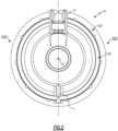
- the VAFN 42 may be separated into at least two sectors 42A-42B ( Figure 2 ) defined between the pylon P and a lower Bi-Fi splitter L which typically interconnects a larger diameter fan duct reverser cowl and a smaller diameter core cowl. It should be understood that although two segments are illustrated, any number of sectors may alternatively or additionally be provided.
- the VAFN 42 selectively defines an auxiliary port system 50 having a first fan nacelle section 52 that include a thrust reverser cowl and a second fan nacelle section 54 that includes a VAFN cowl movably mounted relative the first fan nacelle section 52.
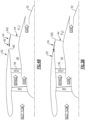
- the second fan nacelle section 54 axially slides along the engine axis A relative the fixed first fan nacelle section 52 to change the effective area of the fan nozzle exit area 44. That is, as the stroke of the second fan nacelle section 54 varies, the leading edge of the second fan nacelle section 54 is either covered by the first fan nacelle section 52 ( Figures 3A and 3B ) or the leading edge is uncovered to define an auxiliary port 60 ( Figures 4A and 4B ).
- the second fan nacelle section 54 slides along a track assembly 56A, 56B within each sectors 42A-42 ( Figures 3A and 4A ) in response to an actuator 58.
- the track assembly 56A, 56B may be located from the first fan nacelle section 52 adjacent the respective pylon P and the lower Bi-Fi splitter L.
- the VAFN 42 changes the physical area and geometry of the bypass flow path 40 during particular flight conditions.
- the bypass flow B is effectively altered by sliding of the second fan nacelle section 54 relative the first fan nacelle section 52 between a closed position ( Figures 3A and 3B ) and an open position ( Figures 4A and 4B ). Movement of the second fan nacelle section 54 forward along the track assembly 56A, 56B toward the first fan nacelle section 52 closes the auxiliary port 60 between the second fan nacelle section 54 and the first fan nacelle section 52 to essentially provide a decrease in the fan nozzle exit area 44 toward exit area F0 ( Figure 4A ).
- the VAFN 42 communicates with the controller C to move the second fan nacelle section 54 relative the first fan nacelle section 52 of the auxiliary port system 50 to effectively vary the area defined by the fan nozzle exit area 44.
- Various control systems including an engine controller or an aircraft flight control system may also be usable with the present invention.
- engine thrust and fuel economy are maximized during each flight regime by varying the fan nozzle exit area.
- engine bypass flow is selectively vectored to provide, for example only, trim balance, thrust controlled maneuvering, enhanced ground operations and short field performance.
- the second fan nacelle section 54 includes a first and second VAFN cowl 70 within each sector 42A-42B.
- Each VAFN cowl 70 is respectively supported by the track assembly 56A, 56B.
- track assembly 56A is essentially identical, only track assembly 56A will be described in detail herein.
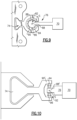
- the track assembly 56A generally includes a hinge beam 72, a first track slider 74, a second track slider 76 and a VAFN cowl mount 78.
- the hinge beam 72 may be fixed to the first fan nacelle section 52, the engine pylon P, lower Bi-Fi splitter L or other fixed structure.
- the first track slider 74 slides relative the hinge beam 72 and the second track slider 76 slides relative the first track slider 74.
- the first track slider 74 generally supports a thrust reverse assembly and the second track slider 76 supports the VAFN cowl 70 such that the thrust reverse assembly and the VAFN cowl 70 may be operated in an independent manner.
- the first track slider 74 defines a first interface 80 with the hinge beam 72 such as a dovetail interface.
- the second track slider 76 defines a second interface 82 with the first track slider 74 such as a semi-cylindrical interface.
- the second interface 82 is more closely controlled than the first interface 80. It should be understood that various interfaces may alternatively be utilized.
- the second track slider 76 supports the VAFN cowl mount 78 which supports the VAFN cowl 70.
- the first track slider 74 generally supports the thrust reverse cowl assembly (TR) and the second track slider 76 supports the VAFN cowl 70 such that the thrust reverse cowl and the VAFN cowl 70 may be operated in an independent manner.
- the first track slider 74 generally supports the thrust reverse cowl assembly (TR) thereby defines the range of movement of the thrust reverse cowl assembly (TR) between the closed position ( Figure 7 ) and an open position ( Figure 8 ) generally along the engine axis A.
- the second track slider 76 thereby defines the range of movement of the VAFN cowl 70 between the closed position ( Figure 7 ) and an open position ( Figure 8 ) relative the thrust reverse cowl assembly (TR) generally along the engine axis A.
- the second interface 82 includes a bearing assembly 84 that includes a multiple of ball bearings 86 between a male section 88 of the second track slider 76 and a female section 90 of the first track slider 74.
- the bearing assembly 84 may be mounted within the female section 90 of the first track slider 74 and support the multiple of ball bearings 86 arranged in rows spaced about the circumference of the male section 88 along axis S.
- the male section 88 of the second track slider 76 interfaces with the female section 90 of the first track slider 74 upon the bearing assembly 84.
- the male section 88 also may rotate in a radial direction about axis S with respect to female section 90 such that under certain flow conditions the phasing between the unsteady aerodynamic loads and the displacement of the resonant modes of the structure are such that the net work of the fluid on the structure over an oscillation period is greater than zero.
- the amplitude of the deflections grows substantially over time resulting in high stress in the structure. This phenomenon is referred to as aeroelastic instability or flutter.
- Applicant has determined that by closely controlling the tolerance between the male section 88 of the second track slider 76 with the female section 90 of the first track slider 74 through the bearing assembly 84, the aeroelastic instability or flutter of the VAFN cowl 70 is altered to thereby effectively increase the flutter margin. That is, the bearing assembly 84 facilitates low resistance movement of the VAFN cowl 70 along the axis S yet closely controls the rotational movement about axis S such that a fixed boundary condition is maintained in the radial direction about axis S to maintain the airfoil stiffness of the VAFN cowl 70 and advantageously effect the natural frequency and mode shape of the vibration thereof.
- the second interface 82 include includes a bearing assembly 92 between a male section 88' of the second track slider 76 and a female section 90' of the first track slider 74.
- the bearing assembly 92 includes a multiple of rollers 94 which roll generally parallel to axis S and are supported within a track 96 formed by the VAFN cowl 70. That is, the bearing assembly 92 facilitates low resistance movement of the VAFN cowl 70 along axis S while closely controlling the VAFN cowl 70 about axis S in a radial direction.
Landscapes
- Engineering & Computer Science (AREA)
- Chemical & Material Sciences (AREA)
- Combustion & Propulsion (AREA)
- Mechanical Engineering (AREA)
- General Engineering & Computer Science (AREA)
- Structures Of Non-Positive Displacement Pumps (AREA)
- Control Of Turbines (AREA)
Claims (8)
- Variable Bläserdüse (42) für ein Gasturbinentriebwerk (10) mit hohem Bypass, umfassend:einen Scharnierbalken (72);einen ersten Schienenschieber (74), der relativ zu dem Scharnierbalken (72) entlang einer ersten Schnittstelle beweglich ist;einen zweiten Schienenschieber (76), der relativ zu dem ersten Schienenschieber (74) entlang einer zweiten Schnittstelle (82) beweglich ist, die eine Lageranordnung (84) beinhaltet; undeine VAFN-Haube (70), die an dem zweiten Schienenschieber (76) montiert ist,wobei die zweite Schnittstelle (82) einen männlichen Abschnitt (88) des zweiten Schienenschiebers (76) und einen weiblichen Abschnitt (90) des ersten Schienenschiebers (74) beinhaltet, und die Lageranordnung (84) zwischen dem männlichen Abschnitt (88) und dem weiblichen Abschnitt (90) montiert ist, wobei der männliche Abschnitt (88) im Querschnitt ein Halbkreis ist, und dadurch gekennzeichnet, dassdie Lageranordnung (84) eine Mehrzahl von Kugellagern (86) beinhaltet, die in Reihen um den Umfang des männlichen Abschnitts (88) beabstandet angeordnet ist.
- Variable Bläserdüse (42) für ein Gasturbinentriebwerk (10) mit hohem Bypass, umfassend:einen Scharnierbalken (72);einen ersten Schienenschieber (74), der relativ zu dem Scharnierbalken (72) entlang einer ersten Schnittstelle beweglich ist;einen zweiten Schienenschieber (76), der relativ zu dem ersten Schienenschieber (74) entlang einer zweiten Schnittstelle (82) beweglich ist, die eine Lageranordnung (92) beinhaltet; undeine VAFN-Haube (70), die an dem zweiten Schienenschieber (76) montiert ist,dadurch gekennzeichnet, dass:
die Lageranordnung (92) eine Mehrzahl von Rollenlagern (94) beinhaltet. - Variable Bläserdüse (42) nach Anspruch 2, wobei die VAFN-Haube (70) eine Schiene trägt, die die Mehrzahl von Rollenlagern (94) aufnimmt.
- Gondelanordnung (N) für ein Gasturbinentriebwerk (10) mit hohem Bypass, umfassend:eine Kerngondel (12), die um eine Triebwerksmittelachse (A) herum definiert ist;eine Bläsergondel (34), die mindestens teilweise um die Kerngondel (12) herum montiert ist, um einen Bläser-Bypass-Strömungspfad (40) zu definieren; unddie variable Bläserdüse (42) nach Anspruch 1, 2 oder 3 in Verbindung mit dem Bläser-Bypass-Strömungspfad (40), wobei die variable Bläserdüse (42) einen ersten Bläsergondelabschnitt (52) und einen zweiten Bläsergondelabschnitt (54) aufweist, wobei der zweite Bläsergondelabschnitt (54) die VAFN-Haube (70) beinhaltet, die relativ zu dem ersten Bläsergondelabschnitt (52) entlang einer Schienenanordnung beweglich ist, um eine Bläserdüsen-Austrittsfläche (44) zu verändern und den Bläser-Bypass-Luftstrom einzustellen, wobei die Schienenanordnung Folgendes umfasst:den Scharnierbalken (72), der an dem ersten Bläsergondelabschnitt (52) befestigt ist;den ersten Schienenschieber (74); undden zweiten Schienenschieber (76), wobei der zweite Schienenschieber (76) an der VAFN-Haube (70) montiert ist.
- Anordnung (N) nach Anspruch 4, wobei der erste Schienenschieber (74) eine Schubumkehranordnung trägt.
- Anordnung (N) nach Anspruch 5, wobei der erste Schienenschieber (74) relativ zu dem zweiten Schienenschieber (76) unabhängig beweglich ist.
- Anordnung (N) nach Anspruch 4, 5 oder 6, wobei der erste Bläsergondelabschnitt (52) fest ist und der zweite Bläsergondelabschnitt (54) entlang der Achse (A) relativ zu dem ersten Bläsergondelabschnitt (52) axial verschiebbar ist, um eine effektive Fläche des Bläserdüsen-Austrittsbereichs (44) so zu ändern, dass, wenn sich ein Hub des zweiten Bläsergondelabschnitts (54) ändert, entweder eine Vorderkante des zweiten Bläsergondelabschnitts (54) durch den ersten Bläsergondelabschnitt (52) abgedeckt wird oder die Vorderkante freigelegt wird, um eine Hilfsöffnung (60) zu definieren.
- Gasturbinentriebwerk (10) mit hohem Bypass, umfassend:ein Kerntriebwerk, das um eine Achse definiert ist;ein Getriebesystem (22), das durch das Kerntriebwerk angetrieben wird;einen Turbobläser (20), der durch das Getriebesystem (22) um die Achse angetrieben wird; unddie Gondelanordnung (N) nach einem der Ansprüche 4 bis 7, wobei die Kerngondel (12) mindestens teilweise um das Kerntriebwerk herum definiert ist.
Applications Claiming Priority (4)
| Application Number | Priority Date | Filing Date | Title |
|---|---|---|---|
| US200962452509P | 2009-11-24 | 2009-11-24 | |
| US12/624,525 US8443586B2 (en) | 2009-11-24 | 2009-11-24 | Variable area fan nozzle bearing track |
| EP10784423.5A EP2504552B8 (de) | 2009-11-24 | 2010-11-24 | Variable lüfterdüse mit lagerschiene |
| PCT/US2010/057974 WO2011066365A2 (en) | 2009-11-24 | 2010-11-24 | Variable area fan nozzle bearing track |
Related Parent Applications (2)
| Application Number | Title | Priority Date | Filing Date |
|---|---|---|---|
| EP10784423.5A Division-Into EP2504552B8 (de) | 2009-11-24 | 2010-11-24 | Variable lüfterdüse mit lagerschiene |
| EP10784423.5A Division EP2504552B8 (de) | 2009-11-24 | 2010-11-24 | Variable lüfterdüse mit lagerschiene |
Publications (2)
| Publication Number | Publication Date |
|---|---|
| EP3825538A1 EP3825538A1 (de) | 2021-05-26 |
| EP3825538B1 true EP3825538B1 (de) | 2023-11-01 |
Family
ID=44061050
Family Applications (2)
| Application Number | Title | Priority Date | Filing Date |
|---|---|---|---|
| EP20215392.0A Active EP3825538B1 (de) | 2009-11-24 | 2010-11-24 | Variable bläserdüse mit lagerschiene |
| EP10784423.5A Active EP2504552B8 (de) | 2009-11-24 | 2010-11-24 | Variable lüfterdüse mit lagerschiene |
Family Applications After (1)
| Application Number | Title | Priority Date | Filing Date |
|---|---|---|---|
| EP10784423.5A Active EP2504552B8 (de) | 2009-11-24 | 2010-11-24 | Variable lüfterdüse mit lagerschiene |
Country Status (3)
| Country | Link |
|---|---|
| US (1) | US8443586B2 (de) |
| EP (2) | EP3825538B1 (de) |
| WO (1) | WO2011066365A2 (de) |
Families Citing this family (24)
| Publication number | Priority date | Publication date | Assignee | Title |
|---|---|---|---|---|
| US20140174056A1 (en) | 2008-06-02 | 2014-06-26 | United Technologies Corporation | Gas turbine engine with low stage count low pressure turbine |
| US20130202402A1 (en) * | 2010-02-15 | 2013-08-08 | Alan Roy Stuart | Articulating slider track |
| US8667802B2 (en) * | 2010-05-06 | 2014-03-11 | Spirit Aerosystems, Inc. | Variable fan duct nozzle translatable core/inner cowl including two overlapping portions made of different materials |
| FR2968635B1 (fr) * | 2010-12-14 | 2012-12-14 | Aircelle Sa | Nacelle pour turboreacteur d’aeronef double flux |
| BR102012028942B1 (pt) * | 2011-12-30 | 2021-06-15 | United Technologies Corporation | Motor de turbina a gás |
| US8869508B2 (en) * | 2012-01-31 | 2014-10-28 | United Technologies Corporation | Gas turbine engine variable area fan nozzle control |
| FR2988978B1 (fr) * | 2012-03-28 | 2014-06-27 | Safran | Support boitier fadec en materiau composite |
| US20140076998A1 (en) * | 2012-09-19 | 2014-03-20 | United Technologies Corporation | System for decoupling drive shaft of variable area fan nozzle |
| FR2997925B1 (fr) * | 2012-11-09 | 2016-03-04 | Aircelle Sa | Ensemble de guidage pour ensemble unitaire mobile de nacelle pour turboreacteur |
| US10240561B2 (en) * | 2013-03-15 | 2019-03-26 | United Technologies Corporation | Aerodynamic track fairing for a gas turbine engine fan nacelle |
| US9581109B1 (en) * | 2013-04-11 | 2017-02-28 | Geoffrey P. Pinto | Axially translating and radially tilting fan nozzle segments with combined actuation and position sensing |
| US10040563B1 (en) * | 2013-04-11 | 2018-08-07 | Geoffrey P. Pinto | Dual panel actuator system for jet engines |
| US9488130B2 (en) | 2013-10-17 | 2016-11-08 | Honeywell International Inc. | Variable area fan nozzle systems with improved drive couplings |
| CN103835836B (zh) * | 2014-03-10 | 2015-09-09 | 金剑 | 一种涵道比可控的燃气轮机 |
| US9869190B2 (en) | 2014-05-30 | 2018-01-16 | General Electric Company | Variable-pitch rotor with remote counterweights |
| US10161356B2 (en) * | 2014-06-02 | 2018-12-25 | Ge Aviation Systems Llc | Integrated thrust reverser actuation system |
| US20170342941A1 (en) * | 2014-07-11 | 2017-11-30 | Mra Systems, Llc | Integrated thrust reverser actuation system |
| US10072510B2 (en) | 2014-11-21 | 2018-09-11 | General Electric Company | Variable pitch fan for gas turbine engine and method of assembling the same |
| US10100653B2 (en) | 2015-10-08 | 2018-10-16 | General Electric Company | Variable pitch fan blade retention system |
| US11674435B2 (en) | 2021-06-29 | 2023-06-13 | General Electric Company | Levered counterweight feathering system |
| US11795964B2 (en) | 2021-07-16 | 2023-10-24 | General Electric Company | Levered counterweight feathering system |
| US11754019B2 (en) | 2021-12-17 | 2023-09-12 | Rohr, Inc. | Articulating slider for nacelle |
| US12601271B2 (en) | 2022-10-21 | 2026-04-14 | General Electric Company | Variable pitch fan of a gas turbine engine |
| CN119146742B (zh) * | 2024-11-20 | 2025-04-25 | 四川鸿浩天富实业有限公司 | 一种具有隔热节能功能的窑炉 |
Family Cites Families (48)
| Publication number | Priority date | Publication date | Assignee | Title |
|---|---|---|---|---|
| FR1271544A (fr) * | 1960-07-11 | 1961-09-15 | Nord Aviation | Combiné turboréacteur-statoréacteur |
| GB1166093A (en) | 1965-12-22 | 1969-10-01 | Chepos Zd Y Chemickeho A Potra | Hydraulic Ingot Stripper |
| US3673802A (en) | 1970-06-18 | 1972-07-04 | Gen Electric | Fan engine with counter rotating geared core booster |
| GB1418905A (en) * | 1972-05-09 | 1975-12-24 | Rolls Royce | Gas turbine engines |
| US3779010A (en) * | 1972-08-17 | 1973-12-18 | Gen Electric | Combined thrust reversing and throat varying mechanism for a gas turbine engine |
| US3879941A (en) * | 1973-05-21 | 1975-04-29 | Gen Electric | Variable cycle gas turbine engine |
| US3931708A (en) * | 1973-10-11 | 1976-01-13 | United Technologies Corporation | Variable flap for a variable pitch ducted fan propulsor |
| US4043121A (en) * | 1975-01-02 | 1977-08-23 | General Electric Company | Two-spool variable cycle engine |
| US4085583A (en) * | 1975-03-31 | 1978-04-25 | The Boeing Company | Method for selectively switching motive fluid supply to an aft turbine of a multicycle engine |
| US4068471A (en) * | 1975-06-16 | 1978-01-17 | General Electric Company | Variable cycle engine with split fan section |
| US4175384A (en) * | 1977-08-02 | 1979-11-27 | General Electric Company | Individual bypass injector valves for a double bypass variable cycle turbofan engine |
| GB2043786B (en) * | 1979-03-10 | 1983-01-12 | Rolls Royce | Gas turbine engine power plant |
| US4409788A (en) * | 1979-04-23 | 1983-10-18 | General Electric Company | Actuation system for use on a gas turbine engine |
| US4564160A (en) * | 1982-09-29 | 1986-01-14 | The Boeing Company | Thrust reverser blocker door assembly |
| GB2189550A (en) | 1986-04-25 | 1987-10-28 | Rolls Royce | A gas turbine engine powerplant with flow control devices |
| US5101533A (en) * | 1989-10-11 | 1992-04-07 | General Electric Company | Vibration damping hinge joints for variable area jet engine exhaust nozzles |
| CA2091473A1 (en) | 1992-04-20 | 1993-10-21 | Mark J. Wagner | Bypass injector valve for variable cycle aircraft engines |
| US5261227A (en) * | 1992-11-24 | 1993-11-16 | General Electric Company | Variable specific thrust turbofan engine |
| US5524847A (en) * | 1993-09-07 | 1996-06-11 | United Technologies Corporation | Nacelle and mounting arrangement for an aircraft engine |
| US5388964A (en) * | 1993-09-14 | 1995-02-14 | General Electric Company | Hybrid rotor blade |
| US5404713A (en) * | 1993-10-04 | 1995-04-11 | General Electric Company | Spillage drag and infrared reducing flade engine |
| US5402638A (en) * | 1993-10-04 | 1995-04-04 | General Electric Company | Spillage drag reducing flade engine |
| JP3421112B2 (ja) * | 1994-02-25 | 2003-06-30 | 富士写真フイルム株式会社 | 画像記録装置 |
| US5778659A (en) * | 1994-10-20 | 1998-07-14 | United Technologies Corporation | Variable area fan exhaust nozzle having mechanically separate sleeve and thrust reverser actuation systems |
| US5577381A (en) * | 1994-12-06 | 1996-11-26 | United Technologies Corporation | Exhaust nozzle cooling scheme for gas turbine engine |
| US5586431A (en) * | 1994-12-06 | 1996-12-24 | United Technologies Corporation | Aircraft nacelle ventilation and engine exhaust nozzle cooling |
| US5593112A (en) * | 1994-12-06 | 1997-01-14 | United Technologies Corporation | Nacelle air pump for vector nozzles for aircraft |
| US5655360A (en) * | 1995-05-31 | 1997-08-12 | General Electric Company | Thrust reverser with variable nozzle |
| DE59601602D1 (de) * | 1995-11-15 | 1999-05-12 | Prospective Concepts Ag | Ballonkorb |
| FR2742482B1 (fr) | 1995-12-19 | 1998-02-06 | Hurel Dubois Avions | Inverseur de poussee a tuyere a section reglable pour moteur d'avion a reaction |
| US5806303A (en) * | 1996-03-29 | 1998-09-15 | General Electric Company | Turbofan engine with a core driven supercharged bypass duct and fixed geometry nozzle |
| US5809772A (en) * | 1996-03-29 | 1998-09-22 | General Electric Company | Turbofan engine with a core driven supercharged bypass duct |
| US5794432A (en) * | 1996-08-27 | 1998-08-18 | Diversitech, Inc. | Variable pressure and variable air flow turbofan engines |
| US5806302A (en) * | 1996-09-24 | 1998-09-15 | Rohr, Inc. | Variable fan exhaust area nozzle for aircraft gas turbine engine with thrust reverser |
| US5867980A (en) * | 1996-12-17 | 1999-02-09 | General Electric Company | Turbofan engine with a low pressure turbine driven supercharger in a bypass duct operated by a fuel rich combustor and an afterburner |
| US5988980A (en) * | 1997-09-08 | 1999-11-23 | General Electric Company | Blade assembly with splitter shroud |
| JP3302919B2 (ja) * | 1997-11-27 | 2002-07-15 | 株式会社リコー | 光記録媒体の初期化方法及び初期化装置 |
| US6318070B1 (en) * | 2000-03-03 | 2001-11-20 | United Technologies Corporation | Variable area nozzle for gas turbine engines driven by shape memory alloy actuators |
| US6546716B2 (en) | 2001-04-26 | 2003-04-15 | Jean-Pierre Lair | Jet engine nozzle with variable thrust vectoring and exhaust area |
| US6584763B2 (en) * | 2001-08-01 | 2003-07-01 | Rohr, Inc. | Lock for the translating sleeve of a turbofan engine thrust reverser |
| US6729575B2 (en) * | 2002-04-01 | 2004-05-04 | Lockheed Martin Corporation | Propulsion system for a vertical and short takeoff and landing aircraft |
| US6901739B2 (en) * | 2003-10-07 | 2005-06-07 | General Electric Company | Gas turbine engine with variable pressure ratio fan system |
| US7174704B2 (en) * | 2004-07-23 | 2007-02-13 | General Electric Company | Split shroud exhaust nozzle |
| US7340883B2 (en) * | 2004-11-12 | 2008-03-11 | The Boeing Company | Morphing structure |
| US7721549B2 (en) * | 2007-02-08 | 2010-05-25 | United Technologies Corporation | Fan variable area nozzle for a gas turbine engine fan nacelle with cam drive ring actuation system |
| US8038388B2 (en) * | 2007-03-05 | 2011-10-18 | United Technologies Corporation | Abradable component for a gas turbine engine |
| US20080273961A1 (en) * | 2007-03-05 | 2008-11-06 | Rosenkrans William E | Flutter sensing and control system for a gas turbine engine |
| EP2479414B1 (de) | 2007-08-08 | 2015-06-10 | Rohr, Inc. | Verstellbare Fandüse mit Bypass-Strom |
-
2009
- 2009-11-24 US US12/624,525 patent/US8443586B2/en active Active
-
2010
- 2010-11-24 WO PCT/US2010/057974 patent/WO2011066365A2/en not_active Ceased
- 2010-11-24 EP EP20215392.0A patent/EP3825538B1/de active Active
- 2010-11-24 EP EP10784423.5A patent/EP2504552B8/de active Active
Also Published As
| Publication number | Publication date |
|---|---|
| US8443586B2 (en) | 2013-05-21 |
| WO2011066365A3 (en) | 2012-01-05 |
| EP2504552A2 (de) | 2012-10-03 |
| EP2504552B1 (de) | 2020-12-30 |
| WO2011066365A2 (en) | 2011-06-03 |
| EP2504552B8 (de) | 2021-03-17 |
| EP3825538A1 (de) | 2021-05-26 |
| US20110120081A1 (en) | 2011-05-26 |
Similar Documents
| Publication | Publication Date | Title |
|---|---|---|
| EP3825538B1 (de) | Variable bläserdüse mit lagerschiene | |
| EP2504553B1 (de) | Gondelanordnung für eine verstellbare lüfterdüse eines gasturbinenmotors | |
| US20110120078A1 (en) | Variable area fan nozzle track | |
| US8459035B2 (en) | Gas turbine engine with low fan pressure ratio | |
| US10041442B2 (en) | Variable area fan nozzle | |
| EP2074312B1 (de) | Düse des bypasskanals mit variablem querschnitt für die gondel eines gasturbinentriebwerks mit schiebebetätigungssystem | |
| EP2333282B1 (de) | Verstellbare Gebläsedüsenversteifungen und Anordnung | |
| EP2074321B1 (de) | Mantelstromdüse mit variablem austrittsquerschnitt mit adaptiver struktur sowie verfahren zur veränderung des austrittquerschnitts der gebläsedüse einer gasturbine | |
| US20120124964A1 (en) | Gas turbine engine with improved fuel efficiency | |
| EP2028359A2 (de) | Gasturbinenmotor mit axialbeweglicher Fandüse mit variablem Querschnitt | |
| US8365515B2 (en) | Gas turbine engine with fan variable area nozzle, nacelle assembly and method of varying area of a fan nozzle | |
| WO2013147951A1 (en) | Gas turbine engine with fan variable area nozzle for low fan pressure ratio | |
| EP2069630B1 (de) | Gondelanordnung und zugehöriges Verfahren | |
| US20150192298A1 (en) | Gas turbine engine with improved fuel efficiency | |
| US20150132106A1 (en) | Gas turbine engine with low fan pressure ratio | |
| WO2013141932A1 (en) | Gas turbine engine with fan variable area nozzle for low fan pressure ratio | |
| WO2013141934A2 (en) | Gas turbine engine with fan variable area nozzle | |
| EP2809936B1 (de) | Gasturbinenmotor mit erhöhter kraftstoffeffizienz | |
| WO2013141933A1 (en) | Gas turbine engine with fan variable area nozzle to reduce fan instability |
Legal Events
| Date | Code | Title | Description |
|---|---|---|---|
| PUAI | Public reference made under article 153(3) epc to a published international application that has entered the european phase |
Free format text: ORIGINAL CODE: 0009012 |
|
| STAA | Information on the status of an ep patent application or granted ep patent |
Free format text: STATUS: THE APPLICATION HAS BEEN PUBLISHED |
|
| AC | Divisional application: reference to earlier application |
Ref document number: 2504552 Country of ref document: EP Kind code of ref document: P |
|
| AK | Designated contracting states |
Kind code of ref document: A1 Designated state(s): AL AT BE BG CH CY CZ DE DK EE ES FI FR GB GR HR HU IE IS IT LI LT LU LV MC MK MT NL NO PL PT RO RS SE SI SK SM TR |
|
| STAA | Information on the status of an ep patent application or granted ep patent |
Free format text: STATUS: REQUEST FOR EXAMINATION WAS MADE |
|
| 17P | Request for examination filed |
Effective date: 20211126 |
|
| RBV | Designated contracting states (corrected) |
Designated state(s): AL AT BE BG CH CY CZ DE DK EE ES FI FR GB GR HR HU IE IS IT LI LT LU LV MC MK MT NL NO PL PT RO RS SE SI SK SM TR |
|
| GRAP | Despatch of communication of intention to grant a patent |
Free format text: ORIGINAL CODE: EPIDOSNIGR1 |
|
| STAA | Information on the status of an ep patent application or granted ep patent |
Free format text: STATUS: GRANT OF PATENT IS INTENDED |
|
| INTG | Intention to grant announced |
Effective date: 20230516 |
|
| GRAS | Grant fee paid |
Free format text: ORIGINAL CODE: EPIDOSNIGR3 |
|
| GRAA | (expected) grant |
Free format text: ORIGINAL CODE: 0009210 |
|
| STAA | Information on the status of an ep patent application or granted ep patent |
Free format text: STATUS: THE PATENT HAS BEEN GRANTED |
|
| AC | Divisional application: reference to earlier application |
Ref document number: 2504552 Country of ref document: EP Kind code of ref document: P |
|
| AK | Designated contracting states |
Kind code of ref document: B1 Designated state(s): AL AT BE BG CH CY CZ DE DK EE ES FI FR GB GR HR HU IE IS IT LI LT LU LV MC MK MT NL NO PL PT RO RS SE SI SK SM TR |
|
| RAP3 | Party data changed (applicant data changed or rights of an application transferred) |
Owner name: RTX CORPORATION |
|
| REG | Reference to a national code |
Ref country code: GB Ref legal event code: FG4D |
|
| REG | Reference to a national code |
Ref country code: CH Ref legal event code: EP |
|
| REG | Reference to a national code |
Ref country code: DE Ref legal event code: R096 Ref document number: 602010069118 Country of ref document: DE |
|
| REG | Reference to a national code |
Ref country code: IE Ref legal event code: FG4D |
|
| REG | Reference to a national code |
Ref country code: LT Ref legal event code: MG9D |
|
| REG | Reference to a national code |
Ref country code: NL Ref legal event code: MP Effective date: 20231101 |
|
| PG25 | Lapsed in a contracting state [announced via postgrant information from national office to epo] |
Ref country code: GR Free format text: LAPSE BECAUSE OF FAILURE TO SUBMIT A TRANSLATION OF THE DESCRIPTION OR TO PAY THE FEE WITHIN THE PRESCRIBED TIME-LIMIT Effective date: 20240202 |
|
| PG25 | Lapsed in a contracting state [announced via postgrant information from national office to epo] |
Ref country code: IS Free format text: LAPSE BECAUSE OF FAILURE TO SUBMIT A TRANSLATION OF THE DESCRIPTION OR TO PAY THE FEE WITHIN THE PRESCRIBED TIME-LIMIT Effective date: 20240301 |
|
| PG25 | Lapsed in a contracting state [announced via postgrant information from national office to epo] |
Ref country code: LT Free format text: LAPSE BECAUSE OF FAILURE TO SUBMIT A TRANSLATION OF THE DESCRIPTION OR TO PAY THE FEE WITHIN THE PRESCRIBED TIME-LIMIT Effective date: 20231101 |
|
| REG | Reference to a national code |
Ref country code: AT Ref legal event code: MK05 Ref document number: 1627462 Country of ref document: AT Kind code of ref document: T Effective date: 20231101 |
|
| PG25 | Lapsed in a contracting state [announced via postgrant information from national office to epo] |
Ref country code: NL Free format text: LAPSE BECAUSE OF FAILURE TO SUBMIT A TRANSLATION OF THE DESCRIPTION OR TO PAY THE FEE WITHIN THE PRESCRIBED TIME-LIMIT Effective date: 20231101 |
|
| PG25 | Lapsed in a contracting state [announced via postgrant information from national office to epo] |
Ref country code: AT Free format text: LAPSE BECAUSE OF FAILURE TO SUBMIT A TRANSLATION OF THE DESCRIPTION OR TO PAY THE FEE WITHIN THE PRESCRIBED TIME-LIMIT Effective date: 20231101 |
|
| PG25 | Lapsed in a contracting state [announced via postgrant information from national office to epo] |
Ref country code: ES Free format text: LAPSE BECAUSE OF FAILURE TO SUBMIT A TRANSLATION OF THE DESCRIPTION OR TO PAY THE FEE WITHIN THE PRESCRIBED TIME-LIMIT Effective date: 20231101 |
|
| PG25 | Lapsed in a contracting state [announced via postgrant information from national office to epo] |
Ref country code: NL Free format text: LAPSE BECAUSE OF FAILURE TO SUBMIT A TRANSLATION OF THE DESCRIPTION OR TO PAY THE FEE WITHIN THE PRESCRIBED TIME-LIMIT Effective date: 20231101 Ref country code: LT Free format text: LAPSE BECAUSE OF FAILURE TO SUBMIT A TRANSLATION OF THE DESCRIPTION OR TO PAY THE FEE WITHIN THE PRESCRIBED TIME-LIMIT Effective date: 20231101 Ref country code: IS Free format text: LAPSE BECAUSE OF FAILURE TO SUBMIT A TRANSLATION OF THE DESCRIPTION OR TO PAY THE FEE WITHIN THE PRESCRIBED TIME-LIMIT Effective date: 20240301 Ref country code: GR Free format text: LAPSE BECAUSE OF FAILURE TO SUBMIT A TRANSLATION OF THE DESCRIPTION OR TO PAY THE FEE WITHIN THE PRESCRIBED TIME-LIMIT Effective date: 20240202 Ref country code: ES Free format text: LAPSE BECAUSE OF FAILURE TO SUBMIT A TRANSLATION OF THE DESCRIPTION OR TO PAY THE FEE WITHIN THE PRESCRIBED TIME-LIMIT Effective date: 20231101 Ref country code: BG Free format text: LAPSE BECAUSE OF FAILURE TO SUBMIT A TRANSLATION OF THE DESCRIPTION OR TO PAY THE FEE WITHIN THE PRESCRIBED TIME-LIMIT Effective date: 20240201 Ref country code: AT Free format text: LAPSE BECAUSE OF FAILURE TO SUBMIT A TRANSLATION OF THE DESCRIPTION OR TO PAY THE FEE WITHIN THE PRESCRIBED TIME-LIMIT Effective date: 20231101 Ref country code: PT Free format text: LAPSE BECAUSE OF FAILURE TO SUBMIT A TRANSLATION OF THE DESCRIPTION OR TO PAY THE FEE WITHIN THE PRESCRIBED TIME-LIMIT Effective date: 20240301 |
|
| PG25 | Lapsed in a contracting state [announced via postgrant information from national office to epo] |
Ref country code: SE Free format text: LAPSE BECAUSE OF FAILURE TO SUBMIT A TRANSLATION OF THE DESCRIPTION OR TO PAY THE FEE WITHIN THE PRESCRIBED TIME-LIMIT Effective date: 20231101 Ref country code: RS Free format text: LAPSE BECAUSE OF FAILURE TO SUBMIT A TRANSLATION OF THE DESCRIPTION OR TO PAY THE FEE WITHIN THE PRESCRIBED TIME-LIMIT Effective date: 20231101 Ref country code: PL Free format text: LAPSE BECAUSE OF FAILURE TO SUBMIT A TRANSLATION OF THE DESCRIPTION OR TO PAY THE FEE WITHIN THE PRESCRIBED TIME-LIMIT Effective date: 20231101 Ref country code: NO Free format text: LAPSE BECAUSE OF FAILURE TO SUBMIT A TRANSLATION OF THE DESCRIPTION OR TO PAY THE FEE WITHIN THE PRESCRIBED TIME-LIMIT Effective date: 20240201 Ref country code: LV Free format text: LAPSE BECAUSE OF FAILURE TO SUBMIT A TRANSLATION OF THE DESCRIPTION OR TO PAY THE FEE WITHIN THE PRESCRIBED TIME-LIMIT Effective date: 20231101 Ref country code: HR Free format text: LAPSE BECAUSE OF FAILURE TO SUBMIT A TRANSLATION OF THE DESCRIPTION OR TO PAY THE FEE WITHIN THE PRESCRIBED TIME-LIMIT Effective date: 20231101 |
|
| REG | Reference to a national code |
Ref country code: CH Ref legal event code: PL |
|
| PG25 | Lapsed in a contracting state [announced via postgrant information from national office to epo] |
Ref country code: DK Free format text: LAPSE BECAUSE OF FAILURE TO SUBMIT A TRANSLATION OF THE DESCRIPTION OR TO PAY THE FEE WITHIN THE PRESCRIBED TIME-LIMIT Effective date: 20231101 |
|
| PG25 | Lapsed in a contracting state [announced via postgrant information from national office to epo] |
Ref country code: LU Free format text: LAPSE BECAUSE OF NON-PAYMENT OF DUE FEES Effective date: 20231124 |
|
| PG25 | Lapsed in a contracting state [announced via postgrant information from national office to epo] |
Ref country code: CH Free format text: LAPSE BECAUSE OF NON-PAYMENT OF DUE FEES Effective date: 20231130 |
|
| PG25 | Lapsed in a contracting state [announced via postgrant information from national office to epo] |
Ref country code: CZ Free format text: LAPSE BECAUSE OF FAILURE TO SUBMIT A TRANSLATION OF THE DESCRIPTION OR TO PAY THE FEE WITHIN THE PRESCRIBED TIME-LIMIT Effective date: 20231101 |
|
| PG25 | Lapsed in a contracting state [announced via postgrant information from national office to epo] |
Ref country code: SK Free format text: LAPSE BECAUSE OF FAILURE TO SUBMIT A TRANSLATION OF THE DESCRIPTION OR TO PAY THE FEE WITHIN THE PRESCRIBED TIME-LIMIT Effective date: 20231101 |
|
| PG25 | Lapsed in a contracting state [announced via postgrant information from national office to epo] |
Ref country code: SM Free format text: LAPSE BECAUSE OF FAILURE TO SUBMIT A TRANSLATION OF THE DESCRIPTION OR TO PAY THE FEE WITHIN THE PRESCRIBED TIME-LIMIT Effective date: 20231101 Ref country code: SK Free format text: LAPSE BECAUSE OF FAILURE TO SUBMIT A TRANSLATION OF THE DESCRIPTION OR TO PAY THE FEE WITHIN THE PRESCRIBED TIME-LIMIT Effective date: 20231101 Ref country code: LU Free format text: LAPSE BECAUSE OF NON-PAYMENT OF DUE FEES Effective date: 20231124 Ref country code: IT Free format text: LAPSE BECAUSE OF FAILURE TO SUBMIT A TRANSLATION OF THE DESCRIPTION OR TO PAY THE FEE WITHIN THE PRESCRIBED TIME-LIMIT Effective date: 20231101 Ref country code: EE Free format text: LAPSE BECAUSE OF FAILURE TO SUBMIT A TRANSLATION OF THE DESCRIPTION OR TO PAY THE FEE WITHIN THE PRESCRIBED TIME-LIMIT Effective date: 20231101 Ref country code: DK Free format text: LAPSE BECAUSE OF FAILURE TO SUBMIT A TRANSLATION OF THE DESCRIPTION OR TO PAY THE FEE WITHIN THE PRESCRIBED TIME-LIMIT Effective date: 20231101 Ref country code: CZ Free format text: LAPSE BECAUSE OF FAILURE TO SUBMIT A TRANSLATION OF THE DESCRIPTION OR TO PAY THE FEE WITHIN THE PRESCRIBED TIME-LIMIT Effective date: 20231101 Ref country code: CH Free format text: LAPSE BECAUSE OF NON-PAYMENT OF DUE FEES Effective date: 20231130 |
|
| REG | Reference to a national code |
Ref country code: BE Ref legal event code: MM Effective date: 20231130 |
|
| REG | Reference to a national code |
Ref country code: DE Ref legal event code: R097 Ref document number: 602010069118 Country of ref document: DE |
|
| PG25 | Lapsed in a contracting state [announced via postgrant information from national office to epo] |
Ref country code: MC Free format text: LAPSE BECAUSE OF FAILURE TO SUBMIT A TRANSLATION OF THE DESCRIPTION OR TO PAY THE FEE WITHIN THE PRESCRIBED TIME-LIMIT Effective date: 20231101 |
|
| PG25 | Lapsed in a contracting state [announced via postgrant information from national office to epo] |
Ref country code: MC Free format text: LAPSE BECAUSE OF FAILURE TO SUBMIT A TRANSLATION OF THE DESCRIPTION OR TO PAY THE FEE WITHIN THE PRESCRIBED TIME-LIMIT Effective date: 20231101 |
|
| PLBE | No opposition filed within time limit |
Free format text: ORIGINAL CODE: 0009261 |
|
| STAA | Information on the status of an ep patent application or granted ep patent |
Free format text: STATUS: NO OPPOSITION FILED WITHIN TIME LIMIT |
|
| REG | Reference to a national code |
Ref country code: IE Ref legal event code: MM4A |
|
| 26N | No opposition filed |
Effective date: 20240802 |
|
| PG25 | Lapsed in a contracting state [announced via postgrant information from national office to epo] |
Ref country code: IE Free format text: LAPSE BECAUSE OF NON-PAYMENT OF DUE FEES Effective date: 20231124 |
|
| PG25 | Lapsed in a contracting state [announced via postgrant information from national office to epo] |
Ref country code: BE Free format text: LAPSE BECAUSE OF NON-PAYMENT OF DUE FEES Effective date: 20231130 |
|
| PG25 | Lapsed in a contracting state [announced via postgrant information from national office to epo] |
Ref country code: SI Free format text: LAPSE BECAUSE OF FAILURE TO SUBMIT A TRANSLATION OF THE DESCRIPTION OR TO PAY THE FEE WITHIN THE PRESCRIBED TIME-LIMIT Effective date: 20231101 |
|
| PG25 | Lapsed in a contracting state [announced via postgrant information from national office to epo] |
Ref country code: SI Free format text: LAPSE BECAUSE OF FAILURE TO SUBMIT A TRANSLATION OF THE DESCRIPTION OR TO PAY THE FEE WITHIN THE PRESCRIBED TIME-LIMIT Effective date: 20231101 Ref country code: IE Free format text: LAPSE BECAUSE OF NON-PAYMENT OF DUE FEES Effective date: 20231124 Ref country code: BE Free format text: LAPSE BECAUSE OF NON-PAYMENT OF DUE FEES Effective date: 20231130 |
|
| PG25 | Lapsed in a contracting state [announced via postgrant information from national office to epo] |
Ref country code: RO Free format text: LAPSE BECAUSE OF FAILURE TO SUBMIT A TRANSLATION OF THE DESCRIPTION OR TO PAY THE FEE WITHIN THE PRESCRIBED TIME-LIMIT Effective date: 20231101 |
|
| PG25 | Lapsed in a contracting state [announced via postgrant information from national office to epo] |
Ref country code: FI Free format text: LAPSE BECAUSE OF FAILURE TO SUBMIT A TRANSLATION OF THE DESCRIPTION OR TO PAY THE FEE WITHIN THE PRESCRIBED TIME-LIMIT Effective date: 20231101 |
|
| PG25 | Lapsed in a contracting state [announced via postgrant information from national office to epo] |
Ref country code: CY Free format text: LAPSE BECAUSE OF FAILURE TO SUBMIT A TRANSLATION OF THE DESCRIPTION OR TO PAY THE FEE WITHIN THE PRESCRIBED TIME-LIMIT; INVALID AB INITIO Effective date: 20101124 |
|
| PG25 | Lapsed in a contracting state [announced via postgrant information from national office to epo] |
Ref country code: HU Free format text: LAPSE BECAUSE OF FAILURE TO SUBMIT A TRANSLATION OF THE DESCRIPTION OR TO PAY THE FEE WITHIN THE PRESCRIBED TIME-LIMIT; INVALID AB INITIO Effective date: 20101124 |
|
| PG25 | Lapsed in a contracting state [announced via postgrant information from national office to epo] |
Ref country code: TR Free format text: LAPSE BECAUSE OF FAILURE TO SUBMIT A TRANSLATION OF THE DESCRIPTION OR TO PAY THE FEE WITHIN THE PRESCRIBED TIME-LIMIT Effective date: 20231101 |
|
| PGFP | Annual fee paid to national office [announced via postgrant information from national office to epo] |
Ref country code: DE Payment date: 20251022 Year of fee payment: 16 |
|
| PGFP | Annual fee paid to national office [announced via postgrant information from national office to epo] |
Ref country code: GB Payment date: 20251022 Year of fee payment: 16 |
|
| PGFP | Annual fee paid to national office [announced via postgrant information from national office to epo] |
Ref country code: FR Payment date: 20251022 Year of fee payment: 16 |
|
| P01 | Opt-out of the competence of the unified patent court (upc) registered |
Free format text: CASE NUMBER: UPC_APP_0018670_3825538/2025 Effective date: 20251221 |