EP3825596A1 - Mamelon de lubrification et accouplement pour en tel mamelon - Google Patents
Mamelon de lubrification et accouplement pour en tel mamelon Download PDFInfo
- Publication number
- EP3825596A1 EP3825596A1 EP20000422.4A EP20000422A EP3825596A1 EP 3825596 A1 EP3825596 A1 EP 3825596A1 EP 20000422 A EP20000422 A EP 20000422A EP 3825596 A1 EP3825596 A1 EP 3825596A1
- Authority
- EP
- European Patent Office
- Prior art keywords
- coupling
- section
- nipple
- longitudinal axis
- connection
- Prior art date
- Legal status (The legal status is an assumption and is not a legal conclusion. Google has not performed a legal analysis and makes no representation as to the accuracy of the status listed.)
- Granted
Links
Images



Classifications
-
- F—MECHANICAL ENGINEERING; LIGHTING; HEATING; WEAPONS; BLASTING
- F16—ENGINEERING ELEMENTS AND UNITS; GENERAL MEASURES FOR PRODUCING AND MAINTAINING EFFECTIVE FUNCTIONING OF MACHINES OR INSTALLATIONS; THERMAL INSULATION IN GENERAL
- F16N—LUBRICATING
- F16N21/00—Conduits; Junctions; Fittings for lubrication apertures
- F16N21/02—Lubricating nipples
-
- F—MECHANICAL ENGINEERING; LIGHTING; HEATING; WEAPONS; BLASTING
- F16—ENGINEERING ELEMENTS AND UNITS; GENERAL MEASURES FOR PRODUCING AND MAINTAINING EFFECTIVE FUNCTIONING OF MACHINES OR INSTALLATIONS; THERMAL INSULATION IN GENERAL
- F16L—PIPES; JOINTS OR FITTINGS FOR PIPES; SUPPORTS FOR PIPES, CABLES OR PROTECTIVE TUBING; MEANS FOR THERMAL INSULATION IN GENERAL
- F16L37/00—Couplings of the quick-acting type
- F16L37/22—Couplings of the quick-acting type in which the connection is maintained by means of balls, rollers or helical springs under radial pressure between the parts
- F16L37/23—Couplings of the quick-acting type in which the connection is maintained by means of balls, rollers or helical springs under radial pressure between the parts by means of balls
-
- F—MECHANICAL ENGINEERING; LIGHTING; HEATING; WEAPONS; BLASTING
- F16—ENGINEERING ELEMENTS AND UNITS; GENERAL MEASURES FOR PRODUCING AND MAINTAINING EFFECTIVE FUNCTIONING OF MACHINES OR INSTALLATIONS; THERMAL INSULATION IN GENERAL
- F16L—PIPES; JOINTS OR FITTINGS FOR PIPES; SUPPORTS FOR PIPES, CABLES OR PROTECTIVE TUBING; MEANS FOR THERMAL INSULATION IN GENERAL
- F16L37/00—Couplings of the quick-acting type
- F16L37/28—Couplings of the quick-acting type with fluid cut-off means
- F16L37/38—Couplings of the quick-acting type with fluid cut-off means with fluid cut-off means in only one of two pipe-end fittings
- F16L37/40—Couplings of the quick-acting type with fluid cut-off means with fluid cut-off means in only one of two pipe-end fittings with a lift valve being opened automatically when the coupling is applied
- F16L37/42—Couplings of the quick-acting type with fluid cut-off means with fluid cut-off means in only one of two pipe-end fittings with a lift valve being opened automatically when the coupling is applied the valve having an axial bore communicating with lateral apertures
-
- F—MECHANICAL ENGINEERING; LIGHTING; HEATING; WEAPONS; BLASTING
- F16—ENGINEERING ELEMENTS AND UNITS; GENERAL MEASURES FOR PRODUCING AND MAINTAINING EFFECTIVE FUNCTIONING OF MACHINES OR INSTALLATIONS; THERMAL INSULATION IN GENERAL
- F16N—LUBRICATING
- F16N21/00—Conduits; Junctions; Fittings for lubrication apertures
- F16N21/04—Nozzles for connection of lubricating equipment to nipples
-
- F—MECHANICAL ENGINEERING; LIGHTING; HEATING; WEAPONS; BLASTING
- F16—ENGINEERING ELEMENTS AND UNITS; GENERAL MEASURES FOR PRODUCING AND MAINTAINING EFFECTIVE FUNCTIONING OF MACHINES OR INSTALLATIONS; THERMAL INSULATION IN GENERAL
- F16N—LUBRICATING
- F16N21/00—Conduits; Junctions; Fittings for lubrication apertures
- F16N2021/005—Modular units
Definitions
- the invention relates to a lubricating nipple, a coupling for a lubricating nipple and a system comprising a lubricating nipple and a coupling.
- Grease nipples have been used in technology for a long time, for example to supply a bearing with a lubricant.
- the grease nipple is a small connector that is connected to a housing of the bearing, for example by means of a thread.
- a grease gun can be attached to the grease nipple with a positive fit using a suitable coupling in order to refill lubricant by means of the grease gun and to lubricate the bearing.
- the lubricating nipple has a valve which is arranged in a longitudinal bore of the lubricating nipple and opens under pressure in order to allow the lubricant to pass through the longitudinal bore. If no coupling or grease gun is connected to the grease nipple, the valve prevents contamination of the grease nipple and the bearing.
- the grease nipples have a spherical section that is intended for connection to a coupling or grease gun. Due to the spherical shape of this section, the lubricating nipple also has an undercut section with which a suitable element of a coupling engages in order to produce the positive connection between the coupling or grease gun and the lubricating nipple.
- a lubricating nipple comprises a connection section for connecting the lubricating nipple to a coupling and a longitudinal axis.
- the connection section has a connection end, an undercut section for engagement of a fastening element of the coupling and a guide section for the fastening element of the coupling, which is arranged between the connection end and the undercut section.
- the connection section between the connection end and the undercut section has a maximum cross section at at least one position along the longitudinal axis in a plane perpendicular to the longitudinal axis.
- the outer contour of the guide section extends in a plane through the longitudinal axis within a straight connection between the outer circumference of the connection end and the maximum cross section.
- cross section refers to the cross-sectional area of the lubricating nipple in a respective plane perpendicular to the longitudinal axis. In the case of a preferably circular cross section, this is by the diameter of the Defined connecting portion, wherein the diameter runs through the longitudinal axis. If the connection section has a maximum cross-section or a maximum cross-sectional area at one position, it of course also has a maximum diameter at this position. The position with the maximum cross section is in particular located at an end of the guide section facing the undercut section.
- the "straight connection" between the outer circumference of the connection end and the maximum cross-section or cross-sectional diameter corresponds, for example, to a circumferential conical surface that results when rotating a distance that connects the outer circumference of the connection end with the outer circumference of the grease nipple at the position along the longitudinal axis at which the connection section has the maximum cross section.
- the lubrication nipple according to the invention is "inwardly" curved or recessed within the guide section, since the guide section is inside and not as in the prior art runs outside the straight connection between the outer circumference of the connection end and the maximum cross section. Since the fastening element of the coupling does not have to be moved over a spherical curvature of the lubricating nipple and instead slides along the inwardly directed guide section when the coupling engages with the lubricating nipple, a connection between the coupling and the lubricating nipple according to the invention can be established more easily.
- the outer contour of the guide section is curved concavely in a plane through the longitudinal axis, wherein the guide section can have an in particular constant radius of curvature.
- concavely curved means that the outer contour of the guide section in a plane in which the longitudinal axis lies, is closer to the longitudinal axis in the radial direction perpendicular to the longitudinal axis than the straight connection between the outer circumference of the connection end and the maximum cross section. Since the fastening element of the coupling in this embodiment runs along a smooth curve without steps or edges due to the concave curvature, the effort required to connect the lubricating nipple to the coupling is particularly low. This also further reduces the wear and tear on the grease nipple. In addition, a guide section with a constant radius of curvature can be produced in a simple manner.
- the outer contour of the guide section can exclusively comprise straight sections.
- Such a guide section can also be produced in a particularly simple manner, but it can have edge-like transitions.
- connection section can furthermore have a section with a constant cross section between the guide section and the connection end, which section is smaller than the cross section within the undercut section.
- this section with a constant cross section and the connection end there can be a further section, the outer contour of which is chamfered inwards in the direction of the longitudinal axis. Since the connection section on the The connecting end thus has a reduced cross-sectional diameter, the coupling in this embodiment can be attached to the lubricating nipple or "threaded" onto it in a particularly simple manner. Furthermore, a section with a constant cross section can again be produced in a simple manner.
- the connection section between the undercut section and the guide section can have a further section with a constant maximum cross section.
- the coupling comprises a coupling body, an inner sleeve connected to the coupling body and a fastening element.
- the inner sleeve has a bore which runs obliquely with respect to the longitudinal axis of the coupling and in which the fastening element is movably arranged.
- the fastening element is designed to fix the lubricating nipple in a predetermined position with respect to the inner sleeve.
- the coupling represents the counterpart to the lubricating nipple according to the invention, the fastening element being able to slide along, for example, the guide section of the lubricating nipple when the coupling is connected to the lubricating nipple. Since the fastening element is movable within the inclined bore of the inner sleeve, the fastening element can be displaced with a small force when the coupling is connected to the grease nipple. The coupling thus allows a simple and quick connection of the coupling to the lubricating nipple due to the inclined bore provided for the movement of the fastening element.
- the fastening element can move away from the longitudinal axis and in the direction of the coupling body, for example, at the same time when the lubricating nipple comes into engagement with the coupling.
- the coupling can additionally have a movable outer sleeve which is prestressed relative to the coupling body by means of an external prestressing element.
- the fastening element of the coupling can furthermore be displaceable into a recessed section of the outer sleeve in order to move the outer sleeve in the direction of the coupling body.
- the fastening element can also move at least partially in the direction of the coupling body during the displacement of the outer sleeve.
- the movable outer sleeve can represent additional guidance and securing of the fastening element.
- the connection between the coupling and the grease nipple can preferably be released by moving the outer sleeve in the opposite direction, i.e. away from the coupling body.
- the outer sleeve can have a projection on an inner surface which forms a bayonet lock with a recess in the coupling body.
- a bayonet lock can lock the outer sleeve on the coupling body. This prevents undesired displacement of the outer sleeve with respect to the coupling body, which could lead to the lubricating nipple becoming detached from the coupling. Preventing such a displacement of the outer sleeve by means of the bayonet lock is particularly advantageous when a lubricant that is to be supplied to an object to be lubricated by means of the lubricating nipple and the coupling is under increased pressure.
- the recess of the coupling body can furthermore comprise several sections which provide a stepped link guide for the projection of the outer sleeve.
- the fastening element comprises a plurality of balls which are arranged in a respective bore of the inner sleeve. There the respective bores of the inner sleeve preferably run at an angle of inclination between 40 ° and 45 ° with respect to the longitudinal axis of the coupling.
- the fastening element can for example comprise four balls.
- the fastening element can be produced in a particularly simple manner, since only balls are required, which are guided in respective inclined bores in the inner sleeve.
- the bores of the inner sleeve preferably run away from the longitudinal axis, and they are aligned in the direction of the coupling body. While the grease nipple comes into engagement with the coupling, the balls in the inclined bores are displaced within the inclined bores, for example due to a guide along the guide section of the grease nipple, that their distance increases with respect to the longitudinal axis.
- the coupling can also have a movable piston.
- the movable piston is arranged within the inner sleeve and has a passage for a lubricant, which is preferably a hydraulic lubricant such as grease or oil.
- the piston is prestressed with respect to the coupling body by means of an inner prestressing element and is then in an initial position when no lubricating nipple is connected to the coupling.
- the piston when the coupling is in communication with a grease nipple, the piston is displaced with respect to the initial position in the direction of the coupling body, and the passage of the piston is in communication with a longitudinal bore of the grease nipple.
- the passage in the movable piston is preferably closed when the piston is in the initial position. This prevents unintentional leakage of the lubricant from the coupling if there is no connection to a grease nipple. Furthermore, the passage of the piston is only opened by the connection with the longitudinal bore of the lubricating nipple when there is actually a connection between the coupling and the lubricating nipple.
- the coupling can additionally comprise a sealing element which is initially arranged between the piston and the inner sleeve when the piston is in the initial position. Due to the movement of the piston when the lubricating nipple engages the coupling, when the coupling is connected to the lubricating nipple, the piston is located between the sealing element and the coupling body.
- the sealing element prevents the lubricant from accidentally escaping from the coupling due to its arrangement between the piston and the inner sleeve.
- the sealing element is located on the other side of the movable piston, which is located between the sealing element and the coupling body, compared to the initial position.
- the piston is sealed against other elements of the coupling, such as against the bore of the inner sleeve and against the outer sleeve, in such a way that the lubricant can only get into the longitudinal bore of the lubricating nipple via the coupling.
- the invention also relates to a system which comprises a lubricating nipple and a coupling as described above.
- the fastener of the coupling then moves when there is lubricant nipple engages the coupling, along the guide portion of the grease nipple and in the bore of the coupling away from the longitudinal axis of the grease nipple to the outside.
- the fastening element is then in engagement with the undercut section of the lubricating nipple.
- the invention also relates to a lubrication system which comprises at least one lubricant channel and at least one lubricating nipple, as described above.
- the lubricant channel can be part of a machine or a technical system in order, for example, to supply a lubricant to a bearing to be lubricated.
- the lubricant that is passed through the lubricant channel is preferably a hydraulic fluid such as oil or grease.
- the invention also relates to the use of a lubricating nipple as described above in a lubricating system.
- FIGS 1A and 1B show a grease nipple 11 according to an embodiment of the invention.
- the lubricating nipple 11 comprises a threaded section 13 and a hexagonal section 14, which are standardized and provided for attaching or screwing the lubricating nipple 11, for example, to a housing of a bearing (not shown).
- the grease nipple 11 has a one-piece nipple body 17, within which a longitudinal bore 19 is located.
- a ball (not shown) can be arranged, which is pretensioned with a spring in order to form a check valve.
- Such a check valve can prevent a lubricant which is supplied to a bearing via the lubricating nipple 11 from accidentally escaping again from the lubricating nipple.
- the grease nipple 11 also has a connection section 15 which is provided for connecting the grease nipple 11 with a coupling 41 according to the invention (cf. FIGS. 2A to 5 ) connect to.
- Fig. 5 shows the connected state of the lubricating nipple 11 and the coupling 41, which thus form a system 100.
- the grease nipple 11 also has a longitudinal axis 20 which runs in the center of the longitudinal bore 19.
- the longitudinal bore 19, the threaded section 13 and the connection section 15 are rotationally symmetrical with respect to the longitudinal axis 20.
- the connection section 15 comprises a connection end 21 at which the longitudinal bore 19 ends, an undercut section 23 and a guide section 25 which is arranged between the connection end 21 and the undercut section 23. Between the connection end 21 and the guide section 25, the connection section 15 further comprises a first straight section 27, while a second straight section 29 is arranged between the guide section 25 and the undercut section 23.
- connection section 15 has a cross-sectional diameter 31 which, in the present example, is 5 mm.
- first straight section 27 has a constant cross-sectional diameter over its entire length along the longitudinal axis 20.
- a chamfered section 28 is arranged between the first straight section 27 and the connection end 21, in which the outer contour of the connection section 15 extends in the direction of the longitudinal axis 20 while reducing the cross-sectional diameter.
- connection section 15 has a cross-sectional diameter 33 which is greater than the cross-sectional diameter 31 at the connection end 21 and, in the present example, is 5.5 mm. Furthermore, the connection section 15 has a straight line within the second Section 29 constantly has its maximum cross-sectional diameter 35, which in the present example is 6.5 mm.
- the cross-sectional diameter of the connection section 15 increases starting from the cross-sectional diameter of the first straight section 27 along the longitudinal axis 20 in the direction of the undercut section 23, so that the guide section 25 has its maximum cross-sectional diameter 35 at its transition to the second straight section 29 .
- the cross-sectional diameter increases within the guide section 25 in such a way that it has a constant radius of curvature R2.
- the grease nipple 11 also has a total length 32 of 15 mm along the longitudinal axis 20, while the threaded section 13 and the connection section 15 have a length 34 and 36 of 5.5 mm and 7 mm, respectively, along the longitudinal axis 20. This results in a length 37 of 2.5 mm for the hexagonal section 14.
- a length 38 including the undercut section 23 up to the connection end 21 is 4.78 mm in the present example, the undercut section 23 having a total length 39 along the longitudinal axis 20 that is 2.04 mm.
- a total length 40 between one end of the undercut section 23 and the connection end 21, i.e. including the guide section 25 and the first straight section 27, but without the undercut section 23, is 2.49 mm.
- FIGs 2A and 2B show the grease nipple 11 of Figures 1A and 1B together with an embodiment of the coupling 41 according to the invention.
- the coupling 41 is provided for connecting the lubricating nipple 11, for example, to a grease gun, not shown.
- the coupling and 41 a coupling end 43 on a coupling body 45, within which there is a longitudinal bore 47 which ends at the coupling end 43.
- the coupling end 43 is provided for connecting the coupling 41 to the grease gun, not shown, so that a hydraulic lubricant reaches the interior of the coupling 41 via the coupling end 43 and into the lubrication nipple 11 or its longitudinal bore 19 via the coupling 41.
- the coupling 41 also has an inner sleeve 49 which surrounds a longitudinal bore 51 and is connected to the coupling body 45 by means of a seal 53.
- the inner sleeve 49 comprises a plurality of bores 55 which run obliquely with respect to a longitudinal axis 20 'of the coupling 41 and in each of which a ball 57 is arranged.
- the inner sleeve 49 has four bores 55 with respective balls 57, three of which in Figure 2B are shown.
- the balls 57 serve as a fastening element for the grease nipple 11, as described below in connection with FIG Figures 3 to 5 is explained in more detail.
- the inclined bores 55 are aligned in the direction of the coupling body 45 or the coupling end 43 of the coupling 41. With respect to the longitudinal axis 20 ', the bores have an angle of inclination 56 (cf. Fig. 5 ), which lies in a range between 40 ° and 45 °. In Fig. 5 Furthermore, respective central axes 58 of two bores 55 are shown purely schematically, which include the angle of inclination 56 with the longitudinal axis 20 ′ of the respective bore 55.
- the coupling 41 further comprises a piston 59 which is arranged inside the inner sleeve 49.
- the piston 59 has a longitudinal bore 61 which begins at an end of the piston 59 facing away from the coupling body 45 and ends inside the piston 59.
- the longitudinal bore 61 of the piston 59 is, however, connected to an inner channel 63 of the piston 59, which is connected to the longitudinal bore 51 of the inner sleeve 49 when the coupling 41 is completely connected to the lubricating nipple 11 (cf. Fig. 5 ).
- the piston 49 is also by means of a inner spring 65 biased with respect to the coupling body 45 on which the inner spring 65 is supported.
- the piston 59 is sealed off from the inner sleeve 49 by means of an O-ring 66 which is located in a recess in the inner sleeve 49.
- the coupling 41 also comprises an outer sleeve 67 which surrounds the inner sleeve 49 and is movable with respect to the coupling body 45.
- the outer sleeve 67 is preloaded with respect to the coupling body 45 by means of an outer spring 69 in the same way as the piston 59, so that the outer spring 69 is also supported on the coupling body 45.
- the outer sleeve 67 is connected to the coupling body 45 at a recessed section 70 of the coupling body 45. The outer sleeve 67 can be displaced with respect to the coupling body 45 along this recessed section 70.
- the outer sleeve 67 has a projection 71 on its inside.
- the outer spring 69 rests on one side of the projection 71, while the projection 71 has an inclined surface 73 on the opposite side, against which the balls 57, which are arranged in the respective bores 55 of the inner sleeve 49, rest.
- the inclined surface 73 also merges into a recessed section 75 of the outer sleeve 67.
- Figure 2B shows a state of the system 100 in which the lubricating nipple 11 and the coupling 41 are aligned along their longitudinal axes 20, 20 ', but are not yet connected to one another.
- the inner spring 65 and the outer spring 69 are relaxed, so that the piston 59 and the outer sleeve 67 are pretensioned with respect to the coupling body 45 and the piston 59 has a maximum distance in relation to the coupling body 45, while a side surface 76 facing the coupling body 45 is the Outer sleeve 67 has a maximum distance 81 in relation to a side surface 77 of the recessed section 70 of the coupling body 45.
- a projection 78 of the piston 59 on a projection 79 of the inner sleeve 49 also lies in the in Figure 2B shown state, a projection 78 of the piston 59 on a projection 79 of the inner sleeve 49.
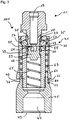
- FIG. 13 shows a state of the system 100 in which the grease nipple 11 is starting to engage with the coupling 41.
- the balls 57 rest on the guide section 25 within the connection section 15 of the lubricating nipple 11, while the connection end 21 rests against the side of the piston 59 of the coupling 41 that faces away from the coupling body 45.
- the outer spring 69 is in the in Fig. 3
- the state shown remains relaxed, so that the maximum distance 81 continues to exist between the side surface 76 of the outer sleeve 67 and the side surface 77 of the recessed section 70 of the coupling body 45.
- the connection end 21 of the grease nipple 11 pushes in the state of Fig. 3 already on the piston 59 in such a way that the projection 78 of the piston 59 no longer rests on the projection 79 of the inner sleeve 49, but is spaced from it.
- the inner spring 65 is also compared to the state of FIG Figure 2B slightly tense.
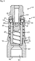
- the balls 57 Since the balls 57 also bear against the inclined surface 73 of the outer sleeve 67, the balls 57 are also displaced along the inclined surface 73 into the recessed portion 75. As a result, the outer sleeve 67 is displaced in the direction of the coupling body 45, so that the side surface 76 of the outer sleeve 67 has a reduced or minimal distance 83 relative to the side surface 77 of the recessed section 70 of the coupling body 45. Due to the displacement of the outer sleeve 67 in the direction of the coupling body 45, the outer spring 69 is also in comparison to the state of Figure 2B and Fig. 3 curious; excited.
- the piston 59 is in the in Fig. 4 shown in comparison to the states of Figure 2B and Fig. 3 further shifted in the direction of the coupling body 45, so that the inner spring 65 compared to the state of Fig. 3 is more excited.
- the O-ring 66 is in the state of Fig. 4 on the side of the piston 59 that faces away from the coupling body 45.
- the piston 59 has in the in Fig. 5
- the state of the system 100 shown in FIG. 1 has a minimum distance relative to the coupling body 45, so that the inner spring 65 in the in FIG Fig. 5 shown compared to the states of FIGS. 2B to 4 is most excited.
- the inner channel 63 of the piston 59 is in the state of Fig. 5 connected to the longitudinal bore 51 of the inner sleeve 49.
- a lubricant that enters the coupling 41 via the coupling end 43 passes via the inner channel 63 and the longitudinal bore 61 of the piston 59 into the longitudinal bore 19 of the lubricating nipple 11.
- the O-ring 66 is located in the in Fig. 5 state shown above the piston 59 and rests on the guide section 25 of the lubricating nipple 11.
- the piston 59 is thus located between the O-ring 66 and the coupling body 45 of the coupling 41.
- the O-ring 66 seals the longitudinal bore 51 of the inner sleeve 49 from the bores 55 of the inner sleeve 49 and thus from the outer sleeve 67.
- the outer sleeve 67 is manually shifted in the direction of the coupling body 45 until the in Fig. 4 state shown is produced.
- the balls 57 come out of engagement of the undercut section 23 of the grease nipple 11, and they move within the respective bore 55 away from the longitudinal axis 20 ', since the piston 59 moves away from the due to the tension of the inner spring 65 Coupling body 45 moved away.
- the lubricating nipple 11 can easily be removed from the coupling 41.
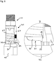
- Fig. 6 shows a sectional view of a variant of the coupling 41, in which an additional securing device in the form of a bayonet lock is provided between the outer sleeve 67 and the coupling body 45.
- the outer sleeve 67 therefore has a projection 89 on its inner surface, while the coupling body 45 has a recess 91 in the recessed section 70.
- the recess 91 of the coupling body 45 comprises a first section 93 and a second section 95.
- the first section 93 has a first depth in relation to an end of the coupling body 45 which faces the outer sleeve 67, while the second section 95 has a corresponding second depth, the first depth being greater than the second Depth is.
- the two sections 93, 95 provide a stepped link guide for the projection 89 of the outer sleeve 67.
- the in Fig. 6 The shown state of the clutch 41 corresponds to the state of Fig. 5 , in which the grease nipple 11 is connected to the coupling 41.
- the projection 89 can be brought into engagement with the recess 91 of the coupling body 45 so that the outer sleeve 67 is locked on the coupling body 67. This prevents an undesired displacement of the outer sleeve 67 relative to the coupling body 45 and thus an undesired loosening of the grease nipple 11 from the coupling 41 of the grease nipple 11 and the coupling 41 is to be supplied to an object to be lubricated.
Landscapes
- Engineering & Computer Science (AREA)
- General Engineering & Computer Science (AREA)
- Mechanical Engineering (AREA)
- Mechanical Operated Clutches (AREA)
- Pivots And Pivotal Connections (AREA)
Applications Claiming Priority (1)
| Application Number | Priority Date | Filing Date | Title |
|---|---|---|---|
| DE102019131619.7A DE102019131619A1 (de) | 2019-11-22 | 2019-11-22 | Schmiernippel und kupplung für einen solchen |
Publications (3)
| Publication Number | Publication Date |
|---|---|
| EP3825596A1 true EP3825596A1 (fr) | 2021-05-26 |
| EP3825596B1 EP3825596B1 (fr) | 2023-06-07 |
| EP3825596C0 EP3825596C0 (fr) | 2023-06-07 |
Family
ID=73597741
Family Applications (1)
| Application Number | Title | Priority Date | Filing Date |
|---|---|---|---|
| EP20000422.4A Active EP3825596B1 (fr) | 2019-11-22 | 2020-11-23 | Mamelon de lubrification et accouplement pour un tel mamelon |
Country Status (2)
| Country | Link |
|---|---|
| EP (1) | EP3825596B1 (fr) |
| DE (1) | DE102019131619A1 (fr) |
Families Citing this family (1)
| Publication number | Priority date | Publication date | Assignee | Title |
|---|---|---|---|---|
| DE102024130256A1 (de) | 2024-10-17 | 2026-04-23 | Rudolf Schlenker | Kupplung zur Ankoppelung an einen Nippel |
Citations (5)
| Publication number | Priority date | Publication date | Assignee | Title |
|---|---|---|---|---|
| US1619455A (en) * | 1922-11-21 | 1927-03-01 | Bassick Mfg Co | Lubricating nipple |
| GB419648A (en) * | 1934-04-14 | 1934-11-15 | Lubrication Corp | Improvements in or relating to lubricating devices |
| FR1122396A (fr) * | 1955-02-23 | 1956-09-05 | Raccord de graissage | |
| US20120061953A1 (en) * | 2010-09-13 | 2012-03-15 | Liu Hsiu-Hsiung | Quick release connector |
| AU2018101263A4 (en) * | 2018-08-01 | 2018-10-04 | Shuoxing Metal Products (Kunshan) CO., LTD. | Quick-Disassembly Nipple Connector Structure |
Family Cites Families (3)
| Publication number | Priority date | Publication date | Assignee | Title |
|---|---|---|---|---|
| DE1777604U (de) * | 1958-07-18 | 1958-11-13 | Tecalemit G M B H Deutsche | Schmiernippel. |
| JP3983728B2 (ja) * | 2003-09-18 | 2007-09-26 | 日東工器株式会社 | 管継手及び管継手のソケット |
| US7673911B2 (en) * | 2008-03-06 | 2010-03-09 | Liu Hsiu-Hsiung | Safety type quick connector |
-
2019
- 2019-11-22 DE DE102019131619.7A patent/DE102019131619A1/de not_active Withdrawn
-
2020
- 2020-11-23 EP EP20000422.4A patent/EP3825596B1/fr active Active
Patent Citations (5)
| Publication number | Priority date | Publication date | Assignee | Title |
|---|---|---|---|---|
| US1619455A (en) * | 1922-11-21 | 1927-03-01 | Bassick Mfg Co | Lubricating nipple |
| GB419648A (en) * | 1934-04-14 | 1934-11-15 | Lubrication Corp | Improvements in or relating to lubricating devices |
| FR1122396A (fr) * | 1955-02-23 | 1956-09-05 | Raccord de graissage | |
| US20120061953A1 (en) * | 2010-09-13 | 2012-03-15 | Liu Hsiu-Hsiung | Quick release connector |
| AU2018101263A4 (en) * | 2018-08-01 | 2018-10-04 | Shuoxing Metal Products (Kunshan) CO., LTD. | Quick-Disassembly Nipple Connector Structure |
Also Published As
| Publication number | Publication date |
|---|---|
| EP3825596B1 (fr) | 2023-06-07 |
| DE102019131619A1 (de) | 2021-05-27 |
| EP3825596C0 (fr) | 2023-06-07 |
Similar Documents
| Publication | Publication Date | Title |
|---|---|---|
| DE69003467T2 (de) | Schnellvervindungs- und Schnellöse-Kupplung. | |
| DE102006023157B3 (de) | Dichtungsanordnung zur Druckentlastung | |
| DE102014010570B4 (de) | Kupplungsteil für eine Kupplung für Druckmittelleitungen | |
| EP2957810B1 (fr) | Pièce de raccord pour un raccord rapide pour des conduites hydrauliques à haute pression | |
| DE3101079C2 (fr) | ||
| DE19614385A1 (de) | Dichtung für einen Ringkolben einer hydraulischen Kupplungs-Ausrückvorrichtung | |
| DE60017999T2 (de) | Verbindungsmittel für Anschliessen eines Rohres an röhrenförmigen Körper | |
| DE3508986A1 (de) | Druckbegrenzungsventil | |
| DE3923579A1 (de) | Anschlussarmatur fuer rohre, insbesondere fuer kunststoffrohre | |
| EP3825596B1 (fr) | Mamelon de lubrification et accouplement pour un tel mamelon | |
| DE20110365U1 (de) | Kupplungsvorrichtung zur Übertragung von Fluiddruck | |
| DE2624013C2 (de) | Rohr- oder Schlauchleitungskupplung | |
| DE4126897A1 (de) | Hydraulisches klemmsystem | |
| DE3877901T2 (de) | Gegen den leitungsdruck verbindbare rohrkupplung. | |
| DE4243844B4 (de) | Anschlußvorrichtung für Rohrleitungen | |
| EP4390207B1 (fr) | Pièce d'accouplement pour un accouplement hydraulique | |
| DE102014009063B4 (de) | Kupplungsteil für eine Schnellkupplung für Hochdruckhydraulikleitungen | |
| DE4139894C2 (de) | Schmiereinrichtung für eine Gleitbahn-Führungseinheit | |
| EP4078002B1 (fr) | Raccord rapide pour raccordement | |
| DE102018100355B4 (de) | Kupplungsvorrichtung zur Verbindung eines Lasthebemittels mit einer Last | |
| DE2724630B2 (de) | Rohrleitungskupplung, insbesondere für Hoch- und Höchstdruckleitungen | |
| DE102017106106A1 (de) | Dichtung für Kolben-Zylinder-Anordnung | |
| EP3992469A1 (fr) | Cylindre de travail amorti en fin de course | |
| DE3632967C2 (fr) | ||
| DE8909376U1 (de) | Steckarmatur zum lösbaren Anschluß von Rohrleitungen |
Legal Events
| Date | Code | Title | Description |
|---|---|---|---|
| PUAI | Public reference made under article 153(3) epc to a published international application that has entered the european phase |
Free format text: ORIGINAL CODE: 0009012 |
|
| STAA | Information on the status of an ep patent application or granted ep patent |
Free format text: STATUS: THE APPLICATION HAS BEEN PUBLISHED |
|
| AK | Designated contracting states |
Kind code of ref document: A1 Designated state(s): AL AT BE BG CH CY CZ DE DK EE ES FI FR GB GR HR HU IE IS IT LI LT LU LV MC MK MT NL NO PL PT RO RS SE SI SK SM TR |
|
| STAA | Information on the status of an ep patent application or granted ep patent |
Free format text: STATUS: REQUEST FOR EXAMINATION WAS MADE |
|
| 17P | Request for examination filed |
Effective date: 20210830 |
|
| RBV | Designated contracting states (corrected) |
Designated state(s): AL AT BE BG CH CY CZ DE DK EE ES FI FR GB GR HR HU IE IS IT LI LT LU LV MC MK MT NL NO PL PT RO RS SE SI SK SM TR |
|
| GRAP | Despatch of communication of intention to grant a patent |
Free format text: ORIGINAL CODE: EPIDOSNIGR1 |
|
| STAA | Information on the status of an ep patent application or granted ep patent |
Free format text: STATUS: GRANT OF PATENT IS INTENDED |
|
| INTG | Intention to grant announced |
Effective date: 20221125 |
|
| GRAS | Grant fee paid |
Free format text: ORIGINAL CODE: EPIDOSNIGR3 |
|
| GRAA | (expected) grant |
Free format text: ORIGINAL CODE: 0009210 |
|
| STAA | Information on the status of an ep patent application or granted ep patent |
Free format text: STATUS: THE PATENT HAS BEEN GRANTED |
|
| AK | Designated contracting states |
Kind code of ref document: B1 Designated state(s): AL AT BE BG CH CY CZ DE DK EE ES FI FR GB GR HR HU IE IS IT LI LT LU LV MC MK MT NL NO PL PT RO RS SE SI SK SM TR |
|
| REG | Reference to a national code |
Ref country code: GB Ref legal event code: FG4D Free format text: NOT ENGLISH |
|
| REG | Reference to a national code |
Ref country code: CH Ref legal event code: EP Ref country code: AT Ref legal event code: REF Ref document number: 1576056 Country of ref document: AT Kind code of ref document: T Effective date: 20230615 Ref country code: DE Ref legal event code: R096 Ref document number: 502020003409 Country of ref document: DE |
|
| U01 | Request for unitary effect filed |
Effective date: 20230626 |
|
| U07 | Unitary effect registered |
Designated state(s): AT BE BG DE DK EE FI FR IT LT LU LV MT NL PT SE SI Effective date: 20230629 |
|
| REG | Reference to a national code |
Ref country code: LT Ref legal event code: MG9D |
|
| PG25 | Lapsed in a contracting state [announced via postgrant information from national office to epo] |
Ref country code: NO Free format text: LAPSE BECAUSE OF FAILURE TO SUBMIT A TRANSLATION OF THE DESCRIPTION OR TO PAY THE FEE WITHIN THE PRESCRIBED TIME-LIMIT Effective date: 20230907 Ref country code: ES Free format text: LAPSE BECAUSE OF FAILURE TO SUBMIT A TRANSLATION OF THE DESCRIPTION OR TO PAY THE FEE WITHIN THE PRESCRIBED TIME-LIMIT Effective date: 20230607 |
|
| PG25 | Lapsed in a contracting state [announced via postgrant information from national office to epo] |
Ref country code: RS Free format text: LAPSE BECAUSE OF FAILURE TO SUBMIT A TRANSLATION OF THE DESCRIPTION OR TO PAY THE FEE WITHIN THE PRESCRIBED TIME-LIMIT Effective date: 20230607 Ref country code: HR Free format text: LAPSE BECAUSE OF FAILURE TO SUBMIT A TRANSLATION OF THE DESCRIPTION OR TO PAY THE FEE WITHIN THE PRESCRIBED TIME-LIMIT Effective date: 20230607 Ref country code: GR Free format text: LAPSE BECAUSE OF FAILURE TO SUBMIT A TRANSLATION OF THE DESCRIPTION OR TO PAY THE FEE WITHIN THE PRESCRIBED TIME-LIMIT Effective date: 20230908 |
|
| U20 | Renewal fee for the european patent with unitary effect paid |
Year of fee payment: 4 Effective date: 20231128 |
|
| PG25 | Lapsed in a contracting state [announced via postgrant information from national office to epo] |
Ref country code: SK Free format text: LAPSE BECAUSE OF FAILURE TO SUBMIT A TRANSLATION OF THE DESCRIPTION OR TO PAY THE FEE WITHIN THE PRESCRIBED TIME-LIMIT Effective date: 20230607 |
|
| PG25 | Lapsed in a contracting state [announced via postgrant information from national office to epo] |
Ref country code: IS Free format text: LAPSE BECAUSE OF FAILURE TO SUBMIT A TRANSLATION OF THE DESCRIPTION OR TO PAY THE FEE WITHIN THE PRESCRIBED TIME-LIMIT Effective date: 20231007 |
|
| PG25 | Lapsed in a contracting state [announced via postgrant information from national office to epo] |
Ref country code: SM Free format text: LAPSE BECAUSE OF FAILURE TO SUBMIT A TRANSLATION OF THE DESCRIPTION OR TO PAY THE FEE WITHIN THE PRESCRIBED TIME-LIMIT Effective date: 20230607 Ref country code: SK Free format text: LAPSE BECAUSE OF FAILURE TO SUBMIT A TRANSLATION OF THE DESCRIPTION OR TO PAY THE FEE WITHIN THE PRESCRIBED TIME-LIMIT Effective date: 20230607 Ref country code: RO Free format text: LAPSE BECAUSE OF FAILURE TO SUBMIT A TRANSLATION OF THE DESCRIPTION OR TO PAY THE FEE WITHIN THE PRESCRIBED TIME-LIMIT Effective date: 20230607 Ref country code: IS Free format text: LAPSE BECAUSE OF FAILURE TO SUBMIT A TRANSLATION OF THE DESCRIPTION OR TO PAY THE FEE WITHIN THE PRESCRIBED TIME-LIMIT Effective date: 20231007 Ref country code: CZ Free format text: LAPSE BECAUSE OF FAILURE TO SUBMIT A TRANSLATION OF THE DESCRIPTION OR TO PAY THE FEE WITHIN THE PRESCRIBED TIME-LIMIT Effective date: 20230607 |
|
| PGFP | Annual fee paid to national office [announced via postgrant information from national office to epo] |
Ref country code: TR Payment date: 20231120 Year of fee payment: 4 |
|
| PG25 | Lapsed in a contracting state [announced via postgrant information from national office to epo] |
Ref country code: PL Free format text: LAPSE BECAUSE OF FAILURE TO SUBMIT A TRANSLATION OF THE DESCRIPTION OR TO PAY THE FEE WITHIN THE PRESCRIBED TIME-LIMIT Effective date: 20230607 |
|
| REG | Reference to a national code |
Ref country code: DE Ref legal event code: R097 Ref document number: 502020003409 Country of ref document: DE |
|
| PLBE | No opposition filed within time limit |
Free format text: ORIGINAL CODE: 0009261 |
|
| STAA | Information on the status of an ep patent application or granted ep patent |
Free format text: STATUS: NO OPPOSITION FILED WITHIN TIME LIMIT |
|
| 26N | No opposition filed |
Effective date: 20240308 |
|
| REG | Reference to a national code |
Ref country code: CH Ref legal event code: PL |
|
| PG25 | Lapsed in a contracting state [announced via postgrant information from national office to epo] |
Ref country code: MC Free format text: LAPSE BECAUSE OF FAILURE TO SUBMIT A TRANSLATION OF THE DESCRIPTION OR TO PAY THE FEE WITHIN THE PRESCRIBED TIME-LIMIT Effective date: 20230607 |
|
| PG25 | Lapsed in a contracting state [announced via postgrant information from national office to epo] |
Ref country code: CH Free format text: LAPSE BECAUSE OF NON-PAYMENT OF DUE FEES Effective date: 20231130 |
|
| PG25 | Lapsed in a contracting state [announced via postgrant information from national office to epo] |
Ref country code: MC Free format text: LAPSE BECAUSE OF FAILURE TO SUBMIT A TRANSLATION OF THE DESCRIPTION OR TO PAY THE FEE WITHIN THE PRESCRIBED TIME-LIMIT Effective date: 20230607 Ref country code: CH Free format text: LAPSE BECAUSE OF NON-PAYMENT OF DUE FEES Effective date: 20231130 |
|
| REG | Reference to a national code |
Ref country code: IE Ref legal event code: MM4A |
|
| PG25 | Lapsed in a contracting state [announced via postgrant information from national office to epo] |
Ref country code: IE Free format text: LAPSE BECAUSE OF NON-PAYMENT OF DUE FEES Effective date: 20231123 |
|
| PG25 | Lapsed in a contracting state [announced via postgrant information from national office to epo] |
Ref country code: IE Free format text: LAPSE BECAUSE OF NON-PAYMENT OF DUE FEES Effective date: 20231123 |
|
| U21 | Renewal fee for the european patent with unitary effect paid with additional fee |
Year of fee payment: 5 Effective date: 20250428 |
|
| GBPC | Gb: european patent ceased through non-payment of renewal fee |
Effective date: 20241123 |
|
| PG25 | Lapsed in a contracting state [announced via postgrant information from national office to epo] |
Ref country code: CY Free format text: LAPSE BECAUSE OF FAILURE TO SUBMIT A TRANSLATION OF THE DESCRIPTION OR TO PAY THE FEE WITHIN THE PRESCRIBED TIME-LIMIT; INVALID AB INITIO Effective date: 20201123 |
|
| PG25 | Lapsed in a contracting state [announced via postgrant information from national office to epo] |
Ref country code: HU Free format text: LAPSE BECAUSE OF FAILURE TO SUBMIT A TRANSLATION OF THE DESCRIPTION OR TO PAY THE FEE WITHIN THE PRESCRIBED TIME-LIMIT; INVALID AB INITIO Effective date: 20201123 |
|
| PG25 | Lapsed in a contracting state [announced via postgrant information from national office to epo] |
Ref country code: GB Free format text: LAPSE BECAUSE OF NON-PAYMENT OF DUE FEES Effective date: 20241123 |