EP3825629B1 - Steuerung von klimaanlagen, aussengeräten, relaiseinheiten, wärmequelleneinheiten und klimaanlagen - Google Patents
Steuerung von klimaanlagen, aussengeräten, relaiseinheiten, wärmequelleneinheiten und klimaanlagen Download PDFInfo
- Publication number
- EP3825629B1 EP3825629B1 EP18927223.0A EP18927223A EP3825629B1 EP 3825629 B1 EP3825629 B1 EP 3825629B1 EP 18927223 A EP18927223 A EP 18927223A EP 3825629 B1 EP3825629 B1 EP 3825629B1
- Authority
- EP
- European Patent Office
- Prior art keywords
- temperature
- controller
- heat
- heat medium
- air conditioning
- Prior art date
- Legal status (The legal status is an assumption and is not a legal conclusion. Google has not performed a legal analysis and makes no representation as to the accuracy of the status listed.)
- Active
Links
Images


Classifications
-
- F—MECHANICAL ENGINEERING; LIGHTING; HEATING; WEAPONS; BLASTING
- F25—REFRIGERATION OR COOLING; COMBINED HEATING AND REFRIGERATION SYSTEMS; HEAT PUMP SYSTEMS; MANUFACTURE OR STORAGE OF ICE; LIQUEFACTION SOLIDIFICATION OF GASES
- F25B—REFRIGERATION MACHINES, PLANTS OR SYSTEMS; COMBINED HEATING AND REFRIGERATION SYSTEMS; HEAT PUMP SYSTEMS
- F25B13/00—Compression machines, plants or systems, with reversible cycle
-
- F—MECHANICAL ENGINEERING; LIGHTING; HEATING; WEAPONS; BLASTING
- F25—REFRIGERATION OR COOLING; COMBINED HEATING AND REFRIGERATION SYSTEMS; HEAT PUMP SYSTEMS; MANUFACTURE OR STORAGE OF ICE; LIQUEFACTION SOLIDIFICATION OF GASES
- F25B—REFRIGERATION MACHINES, PLANTS OR SYSTEMS; COMBINED HEATING AND REFRIGERATION SYSTEMS; HEAT PUMP SYSTEMS
- F25B49/00—Arrangement or mounting of control or safety devices
- F25B49/02—Arrangement or mounting of control or safety devices for compression type machines, plants or systems
-
- F—MECHANICAL ENGINEERING; LIGHTING; HEATING; WEAPONS; BLASTING
- F24—HEATING; RANGES; VENTILATING
- F24F—AIR-CONDITIONING; AIR-HUMIDIFICATION; VENTILATION; USE OF AIR CURRENTS FOR SCREENING
- F24F11/00—Control or safety arrangements
- F24F11/30—Control or safety arrangements for purposes related to the operation of the system, e.g. for safety or monitoring
- F24F11/41—Defrosting; Preventing freezing
- F24F11/42—Defrosting; Preventing freezing of outdoor units
-
- F—MECHANICAL ENGINEERING; LIGHTING; HEATING; WEAPONS; BLASTING
- F24—HEATING; RANGES; VENTILATING
- F24F—AIR-CONDITIONING; AIR-HUMIDIFICATION; VENTILATION; USE OF AIR CURRENTS FOR SCREENING
- F24F3/00—Air-conditioning systems in which conditioned primary air is supplied from one or more central stations to distributing units in the rooms or spaces where it may receive secondary treatment; Apparatus specially designed for such systems
- F24F3/06—Air-conditioning systems in which conditioned primary air is supplied from one or more central stations to distributing units in the rooms or spaces where it may receive secondary treatment; Apparatus specially designed for such systems characterised by the arrangements for the supply of heat-exchange fluid for the subsequent treatment of primary air in the room units
-
- F—MECHANICAL ENGINEERING; LIGHTING; HEATING; WEAPONS; BLASTING
- F25—REFRIGERATION OR COOLING; COMBINED HEATING AND REFRIGERATION SYSTEMS; HEAT PUMP SYSTEMS; MANUFACTURE OR STORAGE OF ICE; LIQUEFACTION SOLIDIFICATION OF GASES
- F25B—REFRIGERATION MACHINES, PLANTS OR SYSTEMS; COMBINED HEATING AND REFRIGERATION SYSTEMS; HEAT PUMP SYSTEMS
- F25B47/00—Arrangements for preventing or removing deposits or corrosion, not provided for in another subclass
- F25B47/02—Defrosting cycles
- F25B47/022—Defrosting cycles hot gas defrosting
- F25B47/025—Defrosting cycles hot gas defrosting by reversing the cycle
-
- F—MECHANICAL ENGINEERING; LIGHTING; HEATING; WEAPONS; BLASTING
- F25—REFRIGERATION OR COOLING; COMBINED HEATING AND REFRIGERATION SYSTEMS; HEAT PUMP SYSTEMS; MANUFACTURE OR STORAGE OF ICE; LIQUEFACTION SOLIDIFICATION OF GASES
- F25B—REFRIGERATION MACHINES, PLANTS OR SYSTEMS; COMBINED HEATING AND REFRIGERATION SYSTEMS; HEAT PUMP SYSTEMS
- F25B2313/00—Compression machines, plants or systems with reversible cycle not otherwise provided for
- F25B2313/003—Indoor unit with water as a heat sink or heat source
-
- F—MECHANICAL ENGINEERING; LIGHTING; HEATING; WEAPONS; BLASTING
- F25—REFRIGERATION OR COOLING; COMBINED HEATING AND REFRIGERATION SYSTEMS; HEAT PUMP SYSTEMS; MANUFACTURE OR STORAGE OF ICE; LIQUEFACTION SOLIDIFICATION OF GASES
- F25B—REFRIGERATION MACHINES, PLANTS OR SYSTEMS; COMBINED HEATING AND REFRIGERATION SYSTEMS; HEAT PUMP SYSTEMS
- F25B2313/00—Compression machines, plants or systems with reversible cycle not otherwise provided for
- F25B2313/023—Compression machines, plants or systems with reversible cycle not otherwise provided for using multiple indoor units
- F25B2313/0233—Compression machines, plants or systems with reversible cycle not otherwise provided for using multiple indoor units in parallel arrangements
-
- F—MECHANICAL ENGINEERING; LIGHTING; HEATING; WEAPONS; BLASTING
- F25—REFRIGERATION OR COOLING; COMBINED HEATING AND REFRIGERATION SYSTEMS; HEAT PUMP SYSTEMS; MANUFACTURE OR STORAGE OF ICE; LIQUEFACTION SOLIDIFICATION OF GASES
- F25B—REFRIGERATION MACHINES, PLANTS OR SYSTEMS; COMBINED HEATING AND REFRIGERATION SYSTEMS; HEAT PUMP SYSTEMS
- F25B2339/00—Details of evaporators; Details of condensers
- F25B2339/04—Details of condensers
- F25B2339/047—Water-cooled condensers
-
- F—MECHANICAL ENGINEERING; LIGHTING; HEATING; WEAPONS; BLASTING
- F25—REFRIGERATION OR COOLING; COMBINED HEATING AND REFRIGERATION SYSTEMS; HEAT PUMP SYSTEMS; MANUFACTURE OR STORAGE OF ICE; LIQUEFACTION SOLIDIFICATION OF GASES
- F25B—REFRIGERATION MACHINES, PLANTS OR SYSTEMS; COMBINED HEATING AND REFRIGERATION SYSTEMS; HEAT PUMP SYSTEMS
- F25B25/00—Machines, plants or systems, using a combination of modes of operation covered by two or more of the groups F25B1/00 - F25B23/00
- F25B25/005—Machines, plants or systems, using a combination of modes of operation covered by two or more of the groups F25B1/00 - F25B23/00 using primary and secondary systems
-
- F—MECHANICAL ENGINEERING; LIGHTING; HEATING; WEAPONS; BLASTING
- F25—REFRIGERATION OR COOLING; COMBINED HEATING AND REFRIGERATION SYSTEMS; HEAT PUMP SYSTEMS; MANUFACTURE OR STORAGE OF ICE; LIQUEFACTION SOLIDIFICATION OF GASES
- F25B—REFRIGERATION MACHINES, PLANTS OR SYSTEMS; COMBINED HEATING AND REFRIGERATION SYSTEMS; HEAT PUMP SYSTEMS
- F25B2600/00—Control issues
- F25B2600/11—Fan speed control
-
- F—MECHANICAL ENGINEERING; LIGHTING; HEATING; WEAPONS; BLASTING
- F25—REFRIGERATION OR COOLING; COMBINED HEATING AND REFRIGERATION SYSTEMS; HEAT PUMP SYSTEMS; MANUFACTURE OR STORAGE OF ICE; LIQUEFACTION SOLIDIFICATION OF GASES
- F25B—REFRIGERATION MACHINES, PLANTS OR SYSTEMS; COMBINED HEATING AND REFRIGERATION SYSTEMS; HEAT PUMP SYSTEMS
- F25B2600/00—Control issues
- F25B2600/13—Pump speed control
-
- F—MECHANICAL ENGINEERING; LIGHTING; HEATING; WEAPONS; BLASTING
- F25—REFRIGERATION OR COOLING; COMBINED HEATING AND REFRIGERATION SYSTEMS; HEAT PUMP SYSTEMS; MANUFACTURE OR STORAGE OF ICE; LIQUEFACTION SOLIDIFICATION OF GASES
- F25B—REFRIGERATION MACHINES, PLANTS OR SYSTEMS; COMBINED HEATING AND REFRIGERATION SYSTEMS; HEAT PUMP SYSTEMS
- F25B2600/00—Control issues
- F25B2600/25—Control of valves
- F25B2600/2515—Flow valves
-
- F—MECHANICAL ENGINEERING; LIGHTING; HEATING; WEAPONS; BLASTING
- F25—REFRIGERATION OR COOLING; COMBINED HEATING AND REFRIGERATION SYSTEMS; HEAT PUMP SYSTEMS; MANUFACTURE OR STORAGE OF ICE; LIQUEFACTION SOLIDIFICATION OF GASES
- F25B—REFRIGERATION MACHINES, PLANTS OR SYSTEMS; COMBINED HEATING AND REFRIGERATION SYSTEMS; HEAT PUMP SYSTEMS
- F25B2700/00—Sensing or detecting of parameters; Sensors therefor
- F25B2700/21—Temperatures
- F25B2700/2103—Temperatures near a heat exchanger
-
- F—MECHANICAL ENGINEERING; LIGHTING; HEATING; WEAPONS; BLASTING
- F25—REFRIGERATION OR COOLING; COMBINED HEATING AND REFRIGERATION SYSTEMS; HEAT PUMP SYSTEMS; MANUFACTURE OR STORAGE OF ICE; LIQUEFACTION SOLIDIFICATION OF GASES
- F25B—REFRIGERATION MACHINES, PLANTS OR SYSTEMS; COMBINED HEATING AND REFRIGERATION SYSTEMS; HEAT PUMP SYSTEMS
- F25B2700/00—Sensing or detecting of parameters; Sensors therefor
- F25B2700/21—Temperatures
- F25B2700/2116—Temperatures of a condenser
- F25B2700/21161—Temperatures of a condenser of the fluid heated by the condenser
-
- F—MECHANICAL ENGINEERING; LIGHTING; HEATING; WEAPONS; BLASTING
- F25—REFRIGERATION OR COOLING; COMBINED HEATING AND REFRIGERATION SYSTEMS; HEAT PUMP SYSTEMS; MANUFACTURE OR STORAGE OF ICE; LIQUEFACTION SOLIDIFICATION OF GASES
- F25B—REFRIGERATION MACHINES, PLANTS OR SYSTEMS; COMBINED HEATING AND REFRIGERATION SYSTEMS; HEAT PUMP SYSTEMS
- F25B2700/00—Sensing or detecting of parameters; Sensors therefor
- F25B2700/21—Temperatures
- F25B2700/2117—Temperatures of an evaporator
- F25B2700/21171—Temperatures of an evaporator of the fluid cooled by the evaporator
- F25B2700/21173—Temperatures of an evaporator of the fluid cooled by the evaporator at the outlet
-
- Y—GENERAL TAGGING OF NEW TECHNOLOGICAL DEVELOPMENTS; GENERAL TAGGING OF CROSS-SECTIONAL TECHNOLOGIES SPANNING OVER SEVERAL SECTIONS OF THE IPC; TECHNICAL SUBJECTS COVERED BY FORMER USPC CROSS-REFERENCE ART COLLECTIONS [XRACs] AND DIGESTS
- Y02—TECHNOLOGIES OR APPLICATIONS FOR MITIGATION OR ADAPTATION AGAINST CLIMATE CHANGE
- Y02B—CLIMATE CHANGE MITIGATION TECHNOLOGIES RELATED TO BUILDINGS, e.g. HOUSING, HOUSE APPLIANCES OR RELATED END-USER APPLICATIONS
- Y02B30/00—Energy efficient heating, ventilation or air conditioning [HVAC]
- Y02B30/70—Efficient control or regulation technologies, e.g. for control of refrigerant flow, motor or heating
Definitions
- the present disclosure relates to a controller of an air conditioning apparatus, an outdoor unit, a relay unit, a heat source unit, and an air conditioning apparatus.
- an indirect air conditioning apparatus that generates hot and/or cold water by a heat source unit such as a heat pump, and delivers the water to an indoor unit through a water pump and a pipe to perform heating and/or cooling in the interior of a room.
- a heat source unit such as a heat pump
- Such an indirect air conditioning apparatus employs water or brine as a use-side heat medium, and thus has been receiving increasing attention in recent years in order to reduce refrigerant usage.
- US 2014/182320 A1 discloses a controller to control an air conditioning apparatus configured to operate in operation modes including a heating mode and a defrosting mode, the air conditioning apparatus comprising: a compressor configured to compress a first heat medium; a first heat exchanger configured to exchange heat between the first heat medium and outdoor air; a second heat exchanger configured to exchange heat between the first heat medium and a second heat medium; a plurality of third heat exchangers each configured to exchange heat between the second heat medium and indoor air; a plurality of flow rate control valves each configured to control a flow rate of the second heat medium flowing through a corresponding one of the plurality of third heat exchangers; and a pump configured to circulate the second heat medium between the plurality of third heat exchangers and the second heat exchanger, in the heating mode, the controller is configured to open the flow rate control valve corresponding to a heat exchanger, of the plurality of third heat exchangers, to which a request for air conditioning has been made, and to close the flow rate control valve corresponding to a heat exchange
- the present disclosure has been made to solve the problem described above, and has an object to provide a controller, of an indirect air conditioning apparatus using a heat medium such as water or brine, which is capable of ensuring heat absorption from the heat medium while preventing freezing of the heat medium, to shorten a length of time required for defrosting operation.
- a heat medium such as water or brine
- a controller of the present disclosure is a controller to control an air conditioning apparatus configured to operate in operation modes including a heating mode and a defrosting mode.
- the air conditioning apparatus includes: a compressor configured to compress a first heat medium; a first heat exchanger configured to exchange heat between the first heat medium and outdoor air; a second heat exchanger configured to exchange heat between the first heat medium and a second heat medium; a plurality of third heat exchangers each configured to exchange heat between the second heat medium and indoor air; a plurality of flow rate control valves each configured to control a flow rate of the second heat medium flowing through a corresponding one of the plurality of third heat exchangers; and a pump configured to circulate the second heat medium between the plurality of third heat exchangers and the second heat exchanger.
- the controller In the heating mode, the controller is configured to open the flow rate control valve corresponding to a heat exchanger, of the plurality of third heat exchangers, to which a request for air conditioning has been made, and to close the flow rate control valve corresponding to a heat exchanger, of the plurality of third heat exchangers, to which the request for air conditioning has not been made.
- the controller In the defrosting mode, when a temperature of the second heat medium is lower than a first determination temperature, the controller is configured to open at least one of the flow rate control valves corresponding to the heat exchangers to which the request for air conditioning has not been made.
- the controller is configured to close the flow rate control valve corresponding to the heat exchanger to which the request for air conditioning has not been made, and the second determination temperature is a temperature higher than or equal to the first determination temperature.
- a defrosting time of the air conditioning apparatus is shortened, and accordingly, comfort during air conditioning is improved.
- FIGS 1-13 show embodiments according to the current invention.
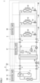
- FIG. 1 shows the configuration of an air conditioning apparatus according to a first embodiment.
- an air conditioning apparatus 1 includes a heat source unit 2, an indoor air conditioning device 3, and a controller 100.
- Heat source unit 2 includes an outdoor unit 10 and a relay unit 20.
- a first heat medium can be exemplified by refrigerant
- a second heat medium can be exemplified by water or brine.
- Outdoor unit 10 includes part of a refrigeration cycle that operates as a heat source or a cold source for the first heat medium.
- Outdoor unit 10 includes a compressor 11, a four-way valve 12, and a first heat exchanger 13.
- Fig. 1 shows an example where four-way valve 12 performs cooling or defrosting, with heat source unit 2 serving as a cold source.
- heat source unit 2 serving as a heat source.
- Relay unit 20 includes a second heat exchanger 22, a pump 23 for circulating the second heat medium between the second heat exchanger and indoor air conditioning device 3, an expansion valve 24, a pressure sensor 25 for detecting a differential pressure ⁇ P before and after pump 23, and a temperature sensor 26 for measuring a temperature of the second heat medium that has passed through second heat exchanger 22.
- Second heat exchanger 22 exchanges heat between the first heat medium and the second heat medium.
- a plate heat exchanger can be used as second heat exchanger 22.
- Outdoor unit 10 and relay unit 20 are connected to each other by pipes 4 and 5 for flowing the first heat medium.
- Compressor 11, four-way valve 12, first heat exchanger 13, expansion valve 24, and second heat exchanger 22 form a first heat medium circuit which is a refrigeration cycle using the first heat medium.
- outdoor unit 10 and relay unit 20 may be integrated together in heat source unit 2. If they are integrated together, pipes 4 and 5 are accommodated in a casing.
- Indoor air conditioning device 3 and relay unit 20 are connected to each other by pipes 6 and 7 for flowing the second heat medium.
- Indoor air conditioning device 3 includes an indoor unit 30, an indoor unit 40 and an indoor unit 50. Indoor units 30, 40 and 50 are connected in parallel with one another between pipe 6 and pipe 7.
- Indoor unit 30 includes a heat exchanger 31, a fan 32 for delivering indoor air to heat exchanger 31, and a flow rate control valve 33 for controlling a flow rate of the second heat medium.
- Heat exchanger 31 exchanges heat between the second heat medium and the indoor air.
- Indoor unit 40 includes a heat exchanger 41, a fan 42 for delivering indoor air to heat exchanger 41, and a flow rate control valve 43 for controlling a flow rate of the second heat medium.
- Heat exchanger 41 exchanges heat between the second heat medium and the indoor air.
- Indoor unit 50 includes a heat exchanger 51, a fan 52 for delivering indoor air to heat exchanger 51, and a flow rate control valve 53 for controlling a flow rate of the second heat medium.
- Heat exchanger 51 exchanges heat between the second heat medium and the indoor air.
- pump 23, second heat exchanger 22, and parallel-connected heat exchanger 31, heat exchanger 41 and heat exchanger 51 form a second heat medium circuit using the second heat medium.
- an air conditioning apparatus having three indoor units is illustrated by way of example in the present embodiment, any number of indoor units may be provided.
- Control units 15, 27 and 36 distributed across outdoor unit 10, relay unit 20 and indoor air conditioning device 3 cooperate with one another to operate as controller 100.
- Controller 100 controls compressor 11, expansion valve 24, pump 23, flow rate control valves 33, 43, 53, and fans 32, 42, 52 in response to outputs from pressure sensor 25 and temperature sensor 26.
- control units 15, 27 and 36 may serve as a controller, and control compressor 11, expansion valve 24, pump 23, flow rate control valves 33, 43, 53, and fans 32, 42, 52 based on data detected by the other control units 15, 27 and 36.
- control units 15 and 27 may cooperate with each other to operate as a controller based on data detected by control unit 36.
- air conditioning apparatus 1 determines, using temperature sensor 26, whether or not the second heat medium is likely to freeze.
- the flow rate control valves are opened and the fans are rotated in the indoor units to introduce heat from the indoor air into the second heat medium, to prevent the freezing. This freezing-preventing operation will be sequentially described below.
- FIG. 2 shows flows of the first heat medium and the second heat medium during the heating operation.
- indoor unit 30 is described as being in an air-conditioning ON state
- indoor units 40 and 50 are described as being in an air-conditioning OFF state.
- the air-conditioning ON state indicates that a request for air conditioning has been made to the indoor unit
- the air-conditioning OFF state indicates that the request for air conditioning has not been made to the indoor unit.
- the air-conditioning OFF state includes a situation where the indoor unit has been turned off by a remote controller or the like, and also a situation where room temperature has reached a set temperature because air conditioning was performed by the indoor unit in the air-conditioning ON state, and the air conditioning is being suspended.
- four-way valve 12 is set such that the first heat medium (refrigerant) is discharged from compressor 11, passes successively through second heat exchanger 22, expansion valve 24 and first heat exchanger 13, and returns to compressor 11.
- the high-temperature and high-pressure first heat medium discharged from compressor 11 exchanges heat with the second heat medium at second heat exchanger 22 and is thereby condensed.
- the condensed first heat medium is decompressed by expansion valve 24, evaporates into a low-temperature gaseous state at first heat exchanger 13, and returns to compressor 11.
- the second heat medium (water or brine) delivered from pump 23 exchanges heat with the first heat medium at second heat exchanger 22 and thereby increases in temperature.
- the second heat medium having the increased temperature is supplied to indoor unit 30 in the air-conditioning ON state, and exchanges heat with the indoor air. Indoor unit 30 in the air-conditioning ON state thereby supplies hot air into the room.
- flow rate control valve 33 corresponding to indoor unit 30 in the air-conditioning ON state is controlled to be in an open state
- flow rate control valves 43 and 53 corresponding to indoor units 40 and 50 in the air-conditioning OFF state are controlled to be in a closed state.
- the second heat medium flows through heat exchanger 31, but does not flow through heat exchangers 41 and 51.
- Fig. 3 shows flows of the first heat medium and the second heat medium in heating-defrosting operation (state A).
- the heating-defrosting operation (state A) is a standard state of heating-defrosting operation.
- four-way valve 12 is set such that the first heat medium (refrigerant) is discharged from compressor 11, passes successively through first heat exchanger 13, expansion valve 24 and second heat exchanger 22, and returns to compressor 11. That is, four-way valve 12 is controlled to be in the same state as that in cooling operation.
- the high-temperature and high-pressure first heat medium discharged from compressor 11 exchanges heat with outdoor air at first heat exchanger 13 and is thereby condensed.
- the condensed first heat medium is decompressed by expansion valve 24, exchanges heat with the second heat medium and turns into a low-temperature gaseous state at second heat exchanger 22, and returns to compressor 11.
- the second heat medium (water or brine) delivered from pump 23 exchanges heat with the first heat medium at second heat exchanger 22 and thereby decreases in temperature.
- the second heat medium having the reduced temperature is supplied to indoor unit 30 in the air-conditioning ON state.
- fan 32 is in a stopped state, and therefore, cold air is not blown into the room.
- flow rate control valve 33 corresponding to indoor unit 30 in the air-conditioning ON state is controlled to be in an open state
- flow rate control valves 43 and 53 corresponding to indoor units 40 and 50 in the air-conditioning OFF state are controlled to be in a closed state.
- the second heat medium flows through heat exchanger 31, but does not flow through heat exchangers 41 and 51.
- the second heat medium exchanges heat with the low-temperature first heat medium and is thereby cooled. Note that when the temperature of the second heat medium at a flow-in portion of second heat exchanger 22 is low, the second heat medium is likely to freeze within second heat exchanger 22.
- Fig. 4 shows flows of the first heat medium and the second heat medium in heating-defrosting operation (state B).
- the heating-defrosting operation (state B) is a state where the temperature of the second heat medium has decreased during the defrosting operation.
- Fig. 4 is different from Fig. 3 in that, during the heating-defrosting operation, the second heat medium is also flowed through the heat exchanges in the air-conditioning OFF state, to absorb heat from the air in rooms in which the indoor units in the air-conditioning OFF state are installed.
- a path of circulation of the first heat medium is the same as that of Fig. 3 .
- the second heat medium circuit in Fig. 4 is described.
- the second heat medium (water or brine) delivered from pump 23 exchanges heat with the first heat medium at second heat exchanger 22 and thereby decreases in temperature.
- the second heat medium having the reduced temperature is supplied to indoor unit 30 in the air-conditioning ON state.
- fan 32 is in a stopped state, and therefore, cold air is not blown into the room.
- the temperature of the second heat medium is monitored by temperature sensor 26.
- the setting of flow rate control valves 43 and 53 corresponding to indoor units 40 and 50 in the air-conditioning OFF state is changed from the closed state to the open state.
- Fans 42 and 52 are also simultaneously driven, to actively perform heat exchange between the indoor air and the second heat medium at heat exchangers 41 and 51.
- the second heat medium increases in temperature, and is thus prevented from freezing. Therefore, the freezing at second heat exchanger 22 is prevented, and the defrosting operation does not need to be interrupted, leading to a shortened defrosting time.
- second determination temperature Y°C may be any temperature higher than or equal to first determination temperature X°C. While second determination temperature Y°C may be the same temperature as first determination temperature X°C, it is preferred to set Y > X to avoid frequent occurrence of switching of the flow path.
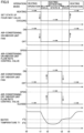
- Fig. 5 shows waveform diagrams for illustrating exemplary control of the heating-defrosting operation in the first embodiment. Between times t0 and t1 in Fig. 5 , heating operation is performed, and the first heat medium and the second heat medium flow as shown in Fig. 2 .
- the state of the four-way valve is set from a heating state to a cooling state.
- the first heat medium and the second heat medium flow as shown in state A of Fig. 3 .
- the heat of the second heat medium is transferred to the first heat medium at second heat exchanger 22, causing the temperature of the second heat medium to decrease gradually, and fall below first determination temperature X°C at time t2.
- the flow of the second heat medium is changed such that the second heat medium also flows through the air-conditioning OFF indoor units as shown in state B of Fig. 4 .
- the indoor air and the second heat medium thereby exchange a greater amount of heat with each other, causing the temperature of the second heat medium to increase gradually.
- Fig. 6 shows the configuration of the controller for controlling the air conditioning apparatus and of a remote controller for remotely controlling the controller.
- a remote controller 200 includes an input device 201, a processor 202, and a transmission device 203.
- Input device 201 includes a push button to switch between ON/OFF of the indoor unit by a user, a button to enter a set temperature, and the like.
- Transmission device 203 is for communicating with controller 100.
- Processor 202 controls transmission device 203 in accordance with an input signal provided from input device 201.
- Controller 100 includes a reception device 101, a processor 102, and a memory 103.
- Memory 103 includes, for example, a read only memory (ROM), a random access memory (RAM), and a flash memory. Note that the flash memory stores an operating system, an application program, and various types of data.
- ROM read only memory
- RAM random access memory
- flash memory stores an operating system, an application program, and various types of data.
- Processor 102 controls overall operation of air conditioning apparatus 1. Controller 100 shown in Fig. 1 is implemented by processor 102 executing the operating system and the application program stored in memory 103. The various types of data stored in memory 103 are referred to during the execution of the application program.
- Reception device 101 is for communicating with remote controller 200. When there are a plurality of indoor units, reception device 101 is provided in each of the plurality of indoor units.
- the processor is included in each of the plurality of control units.
- the plurality of processors cooperate with one another to perform overall control of air conditioning apparatus 1.
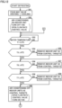
- Fig. 7 is a flowchart for illustrating control performed by the controller in the first embodiment.
- defrosting operation is started when a predetermined defrosting start condition is satisfied.
- the defrosting start condition is satisfied, for example, each time a certain time period elapses, or when the formation of frost on the heat exchanger of the outdoor unit is detected, during heating operation.
- step S1 controller 100 switches four-way valve 12 from a heating operation state to a cooling operation state. Subsequently, in step S2, controller 100 controls an indoor unit in the air-conditioning ON state such that its fan is turned off and its flow rate control valve is opened. This causes the second heat medium to flow as shown in state A of Fig. 3 , for example.
- step S3 controller 100 determines whether or not a temperature T1 of the second heat medium detected at temperature sensor 26 is lower than first determination temperature X°C.
- temperature T1 is higher than or equal to first determination temperature X°C (NO in S3), state A of the defrosting operation shown in Fig. 3 is maintained.
- temperature T1 is lower than first determination temperature X°C (YES in S3), on the other hand, the process proceeds to step S4.
- step S4 controller 100 controls indoor units in the air-conditioning OFF state such that their flow rate control valves are opened and their fans are turned on. This causes the second heat medium to flow as shown in state B of Fig. 4 , for example.
- step S5 controller 100 determines whether or not temperature T1 of the second heat medium detected at temperature sensor 26 is higher than or equal to second determination temperature Y°C.
- second determination temperature Y°C NO in S5
- state B of the defrosting operation shown in Fig. 4 is maintained.
- temperature T1 is higher than or equal to second determination temperature Y°C (YES in S5), on the other hand, the process proceeds to step S6.
- controller 100 controls the indoor units in the air-conditioning OFF state such that their flow rate control valves are closed and their fans are turned off. This causes the flow of the second heat medium to return to original state A as shown in Fig. 3 .
- controller 100 determines whether or not a defrosting end condition is satisfied.
- the defrosting end condition is satisfied, for example, when a certain time period has elapsed since the start of the defrosting, or when the defrosting of the outdoor unit is completed.
- the processes of step S3 and the subsequent steps are repeated again.
- the defrosting end condition is satisfied in step S7, on the other hand, the defrosting operation ends in step S8, and the heating operation is performed again.
- Controller 100 is a controller to control air conditioning apparatus 1 that operates in operation modes including a heating mode and a defrosting mode.
- Air conditioning apparatus 1 includes compressor 11 to compress the first heat medium, first heat exchanger 13 to exchange heat between the first heat medium and outdoor air, second heat exchanger 22 to exchange heat between the first heat medium and the second heat medium, the plurality of third heat exchangers 31, 41 and 51 to exchange heat between the second heat medium and indoor air, the plurality of flow rate control valves 33, 43 and 53 to control the flow rates of the second heat medium flowing through the plurality of third heat exchangers 31, 41 and 51, respectively, and pump 23 to circulate the second heat medium between the plurality of third heat exchangers 31, 41, 51 and second heat exchanger 22.
- controller 100 opens the flow rate control valve corresponding to a heat exchanger, of the plurality of third heat exchangers 31, 41 and 51, to which a request for air conditioning has been made, and closes the flow rate control valves corresponding to heat exchangers, of the plurality of third heat exchangers 31, 41 and 51, to which the request for air conditioning has not been made.
- controller 100 opens at least one of the flow rate control valves corresponding to the heat exchangers to which the request for air conditioning has not been made.
- controller 100 closes the flow rate control valves corresponding to the heat exchangers to which the request for air conditioning has not been made.
- the second heat medium is flowed through the heat exchangers to which the request for air conditioning has not been made. This allows heat transfer from the indoor air to the second heat medium, thus increasing the temperature of the second heat medium.
- air conditioning apparatus 1 further includes the plurality of fans 32, 42 and 52 provided to correspond to the plurality of third heat exchangers 31, 41 and 51, respectively.
- controller 100 drives the fan corresponding to the heat exchanger to which the request for air conditioning has been made, and stops the fan(s) corresponding to the heat exchanger(s) to which the request for air conditioning has not been made.
- controller 100 drives the fans corresponding to the heat exchangers to which the request for air conditioning has not been made.
- controller 100 stops the fans corresponding to the heat exchangers to which the request for air conditioning has not been made.
- the air conditioning apparatus in the first embodiment opens the flow rate control valves and rotates the fans in the indoor units in the air-conditioning OFF state, to increase the temperature of the second heat medium by indoor heat. Accordingly, heat absorption at the second heat exchanger can be ensured while the freezing at the second heat medium circuit is prevented, leading to a shortened length of time required for the defrosting operation.
- the second heat medium decreases in temperature and freezes during cooling operation.
- cooling is performed even at a very low room temperature, which may cause the temperature of the second heat medium to decrease to a temperature close to the freezing temperature.
- a modification of the first embodiment describes control of performing heat exchange with indoor air in the indoor units in the air-conditioning OFF state, when the second heat medium is likely to freeze during cooling operation.
- step S1 in Fig. 7 is not performed because the cooling is being performed.
- the flow rate control valve is opened and the fan is turned on instead of the process of step S2.
- steps S2 through S7 in Fig. 7 are performed, the following operation is performed instead of the process of step S4 when temperature T1 becomes lower than first determination temperature X°C.
- controller 100 opens the flow rate control valves and turns on the fans in the indoor units in the air-conditioning OFF state. Furthermore, the controller increases a rotation speed of the fan of the indoor unit in the air-conditioning ON state (which is performing cooling).
- the controller increases a rotation speed of the fan of the indoor unit in the air-conditioning ON state (which is performing cooling).
- the increased rotation speed of the fan leads to an increased amount of heat exchange.
- the fan is turned on in the indoor unit in the air-conditioning ON state in the modification.
- the operation modes further include a cooling mode in addition to the heating mode and the defrosting mode.
- a cooling mode when the temperature of the second heat medium is higher than second determination temperature Y°C, controller 100 closes the flow rate control valve(s) corresponding to the heat exchanger(s) to which the request for air conditioning has not been made, and when the temperature of the second heat medium is lower than first determination temperature X°C, controller 100 opens the flow rate control valve(s) corresponding to the heat exchanger(s) to which the request for air conditioning has not been made.
- controller 100 stops the fan corresponding to the heat exchanger to which the request for air conditioning has been made.
- controller 100 increases the rotation speed of the fan corresponding to the heat exchanger to which the request for air conditioning has been made.
- controller 100 reduces the rotation speed of the fan corresponding to the heat exchanger to which the request for air conditioning has been made.
- the indoor units in the air-conditioning OFF state are collectively handled in the first embodiment, whereas in a second embodiment, heat is obtained from a number of indoor units suitable for required heat in defrosting operation.
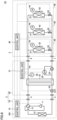
- Fig. 8 shows the configuration of an air conditioning apparatus 1A in the second embodiment.
- indoor units 30, 40 and 50 include temperature sensors 34, 44 and 54, respectively.
- the configuration of air conditioning apparatus 1A is otherwise similar to that of air conditioning apparatus 1 shown in Fig. 1 , and is not described repeatedly.
- Temperature sensors 34, 44 and 54 measure temperatures T2, T3 and T4 of the second heat medium flowing into the indoor units, respectively, and output the temperatures to controller 100.
- controller 100 When the second heat medium is likely to freeze, controller 100 performs freezing-preventing operation of opening the flow rate control valve and turning on the indoor fan, preferentially from an indoor unit having a shorter length of a water pipe of the indoor units in the air-conditioning OFF state.
- Fig. 9 is a flowchart for illustrating control performed during first-time operation in the second embodiment.
- the first-time operation is started when an operation command is entered for the first time after installation.
- controller 100 sets degrees of opening of the flow rate control valves in all of the indoor units to the same degree of opening, and defines temperatures T2, T3 and T4 detected respectively by temperature sensors 34, 44 and 54 as initial temperatures and stores them in the memory.
- controller 100 performs cooling operation as the first-time operation by turning on compressor 11 and turning on pump 23.
- controller 100 defines unit numbers of the indoor units as No. 1/No. 2/No. 3 in the order from an indoor unit in which the difference between the above-described initial temperature and the detected current temperature becomes equal to or greater than Z°C, and stores them in the memory.
- controller 100 ends the cooling operation.
- the unit numbers are assigned to the indoor units in the order from an indoor unit having a shorter length of the pipe for supplying the second heat medium.
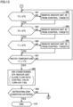
- Fig. 10 is a flowchart for illustrating control performed during defrosting operation in the second embodiment.
- the defrosting operation is started when a predetermined defrosting start condition is satisfied.
- the defrosting start condition is satisfied, for example, each time a certain time period elapses, or when the formation of frost on the heat exchanger of the outdoor unit is detected, during heating operation.
- controller 100 switches four-way valve 12 from a heating operation state to a cooling operation state. Subsequently, in step S22, controller 100 controls an indoor unit in the air-conditioning ON state such that its fan is turned off and its flow rate control valve is opened. This causes the second heat medium to flow as shown in Fig. 3 , for example.
- step S23 controller 100 determines whether or not temperature T1 of the second heat medium detected at temperature sensor 26 is lower than first determination temperature X°C.
- temperature T1 is higher than or equal to first determination temperature X°C (NO in S23)
- the state of the defrosting operation shown in Fig. 3 is maintained.
- temperature T1 is lower than first determination temperature X°C (YES in S23)
- the process proceeds to step S24.
- controller 100 controls an indoor unit having the smallest numerical value as the unit number, of the air-conditioning OFF and fan OFF indoor units, such that its flow rate control valve is opened and its fan is turned on.
- controller 100 determines whether or not temperature T1 of the second heat medium detected at temperature sensor 26 is higher than or equal to second determination temperature Y°C.
- step S26 it is determined whether or not a time period A minute(s) have elapsed since the execution of the process of step S24.
- a minute(s) have not yet elapsed in step S26 (NO in S26)
- the determination process of step S25 is performed again.
- a minute(s) have elapsed in step S26 (YES in S26)
- the process proceeds to step S24.
- step S24 the indoor unit in the air-conditioning OFF state whose fan was turned on the previous time is removed, and therefore, controller 100 controls an indoor unit having the next smallest unit number such that its flow rate control valve is opened and its fan is turned on.
- step S27 controller 100 controls the indoor units in the air-conditioning OFF state such that their flow rate control valves are closed and their fans are turned off. This causes the flow of the second heat medium to return to the original state as shown in Fig. 3 .
- controller 100 determines whether or not a defrosting end condition is satisfied.
- the defrosting end condition is satisfied, for example, when a certain time period has elapsed since the start of the defrosting, or when the defrosting of the outdoor unit is completed.
- the processes of step S23 and the subsequent steps are repeated again.
- the defrosting end condition is satisfied in step S28, on the other hand, the defrosting operation ends in step S29, and the heating operation is performed again.
- controller 100 opens one of the flow rate control valves corresponding to the heat exchangers to which the request for air conditioning has not been made, and when the temperature of the second heat medium is still lower than first determination temperature X°C after the one of the flow rate control valves is opened, controller 100 opens another one of the flow rate control valves corresponding to the heat exchangers to which the request for air conditioning has not been made.
- the fan(s) when the temperature of the second heat medium decreases during the defrosting operation, the fan(s) are turned on and the flow rate control valve(s) are opened in a minimum number of indoor units of the indoor units in the air-conditioning OFF state, to increase the temperature of the second heat medium.
- This can reduce power consumption during the defrosting operation as compared to that in the first embodiment, and can eliminate the need to reduce the temperature of an indoor unit in the air-conditioning OFF state whose temperature need not be reduced, and is therefore advantageous for when the indoor unit in the air-conditioning OFF state starts heating.
- an indoor unit from which heat is to be obtained is determined in consideration of room temperatures of spaces where the indoor units in the air-conditioning OFF state are installed.
- Fig. 11 shows the configuration of an air conditioning apparatus 1B in the third embodiment.
- indoor units 30, 40 and 50 include temperature sensors 35, 45 and 55 for sensing room temperatures, respectively.
- the configuration of air conditioning apparatus 1B is otherwise similar to that of air conditioning apparatus 1A shown in Fig. 8 , and is not described repeatedly.
- Temperature sensors 35, 45 and 55 measure temperatures T5, T6 and T7 of rooms in which indoor units 30, 40 and 50 are installed, and output the temperatures to controller 100.
- Fig. 12 is a flowchart (first half) for illustrating control performed during defrosting operation in the third embodiment.
- the defrosting operation is started when a predetermined defrosting start condition is satisfied.
- the defrosting start condition is satisfied, for example, each time a certain time period elapses, or when the formation of frost on the heat exchanger of the outdoor unit is detected, during heating operation.
- controller 100 switches four-way valve 12 from a heating operation state to a cooling operation state. Subsequently, in step S52, controller 100 controls an indoor unit in the air-conditioning ON state such that its fan is turned off and its flow rate control valve is opened. This causes the second heat medium to flow as shown in Fig. 3 , for example.
- step S53 controller 100 determines whether or not temperature T1 of the second heat medium detected at temperature sensor 26 is lower than first determination temperature X°C.
- temperature T1 is higher than or equal to first determination temperature X°C (NO in S53)
- the state of the defrosting operation shown in Fig. 3 is maintained.
- temperature T1 is lower than first determination temperature X°C (YES in S53)
- the process proceeds to step S54.
- step S54 controller 100 measures temperature T5 of the room in which indoor unit 30 is installed using temperature sensor 35, and determines whether or not temperature T5 is higher than or equal to a third determination temperature K°C.
- controller 100 removes indoor unit 30 from control targets through which the second heat medium is flowed to absorb heat from the indoor air, and proceeds the process to step S56.
- controller 100 proceeds the process to step S56 without performing the process of step S55.
- step S56 controller 100 measures temperature T6 of the room in which indoor unit 40 is installed using temperature sensor 45, and determines whether or not temperature T6 is higher than or equal to third determination temperature K°C.
- step S57 controller 100 removes indoor unit 40 from the control targets through which the second heat medium is flowed to absorb heat from the indoor air, and proceeds the process to step S58.
- step S58 controller 100 proceeds the process to step S58 without performing the process of step S57.
- step S58 controller 100 measures temperature T7 of the room in which indoor unit 50 is installed using temperature sensor 55, and determines whether or not temperature T7 is higher than or equal to third determination temperature K°C.
- step S59 controller 100 removes indoor unit 50 from the control targets through which the second heat medium is flowed to absorb heat from the indoor air, and proceeds the process to step S60.
- step S60 determines whether or not temperature T7 is higher than or equal to determination temperature K°C (YES in S58)
- step S60 the flow rate control valve(s) are opened and the fan(s) are turned on, which correspond to the indoor unit(s) that were not removed from the control targets in the processes of steps S55, S57 and S59 of the indoor units in the air-conditioning OFF state.
- Fig. 13 is a flowchart (second half) for illustrating control performed during defrosting operation in the third embodiment. Following step S60, processes of step S61 and the subsequent steps shown in Fig. 13 are performed.
- step S61 controller 100 measures temperature T5 of the room in which indoor unit 30 is installed using temperature sensor 35, and determines whether or not temperature T5 is higher than or equal to third determination temperature K°C.
- step S62 controller 100 removes indoor unit 30 from the control targets in which heat is absorbed from the indoor air, by closing the corresponding flow rate control valve and turning off the corresponding fan, and proceeds the process to step S63.
- step S63 controller 100 proceeds the process to step S63 without performing the process of step S62.
- step S63 controller 100 measures temperature T6 of the room in which indoor unit 40 is installed using temperature sensor 45, and determines whether or not temperature T6 is higher than or equal to third determination temperature K°C.
- step S64 controller 100 removes indoor unit 40 from the control targets in which heat is absorbed from the indoor air, by closing the corresponding flow rate control valve and turning off the corresponding fan, and proceeds the process to step S65.
- step S65 determines whether or not temperature T6 is higher than or equal to third determination temperature K°C.
- step S65 controller 100 measures temperature T7 of the room in which indoor unit 50 is installed using temperature sensor 55, and determines whether or not temperature T7 is higher than or equal to third determination temperature K°C.
- step S66 controller 100 removes indoor unit 50 from the control targets in which heat is absorbed from the indoor air, by closing the corresponding flow rate control valve and turning off the corresponding fan, and proceeds the process to step S67.
- step S67 controller 100 proceeds the process to step S67 without performing the process of step S66.
- step S67 controller 100 determines whether or not temperature T1 of the second heat medium detected at temperature sensor 26 is higher than or equal to second determination temperature Y°C.
- step S67 When temperature T1 is lower than second determination temperature Y°C in step S67 (NO in S67), the defrosting operation using the indoor unit(s) in the air-conditioning OFF state is continued, and in steps S61 through S66, the processes of monitoring the room temperatures, and the processes of preventing the second heat medium from flowing through the indoor unit(s) in the room(s) having the reduced room temperature are performed.
- temperature T1 is higher than or equal to second determination temperature Y°C (YES in S67)
- the process proceeds to step S68,
- step S68 controller 100 controls the indoor unit(s) in the air-conditioning OFF state such that their flow rate control valve(s) are closed and their fan(s) are turned off. This causes the flow of the second heat medium to return to the original state as shown in Fig. 3 .
- controller 100 determines whether or not a defrosting end condition is satisfied.
- the defrosting end condition is satisfied, for example, when a certain time period has elapsed since the start of the defrosting, or when the defrosting of the outdoor unit is completed.
- the processes of step S53 and the subsequent steps in Fig. 12 are repeated again.
- the defrosting end condition is satisfied in step S69, on the other hand, the defrosting operation ends in step S70, and the heating operation is performed again.
- controller 100 opens the flow rate control valve corresponding to a heat exchanger, of the heat exchangers to which the request for air conditioning has not been made, that is installed in a room having a temperature higher than third determination temperature K°C.
- the fan(s) when the temperature of the second heat medium decreases during the defrosting operation, the fan(s) are turned on and the flow rate control valve(s) are opened to increase the temperature of the second heat medium, while the indoor unit(s) installed in a room having a temperature lower than determination temperature K°C of the indoor units in the air-conditioning OFF state are removed.
- This can prevent blowing of cold air from the indoor unit during the defrosting operation, which causes an occupant in the low-temperature room to feel uncomfortable.
- controller 100 may be disposed in any of outdoor unit 10, relay unit 20 and heat source unit 2.
- Air conditioning apparatuses 1, 1A and 1B in the present embodiment each include: the first heat medium circuit formed by compressor 11, first heat exchanger 13, and second heat exchanger 22; the second heat medium circuit formed by pump 23, second heat exchanger 22, and the plurality of third heat exchangers 31, 41 and 51; and controller 100.
- 1, 1A, 1B air conditioning apparatus
- 2 heat source unit
- 3 indoor air conditioning device
- 4 outdoor unit
- 11 compressor
- 12 four-way valve
- 13, 22, 31, 41, 51 heat exchanger
- 15, 27, 36 control unit
- 20 relay unit
- 23 pump
- 24 expansion valve
- 25 pressure sensor
- 26, 34, 35, 44, 45, 54, 55 temperature sensor
- 30, 40, 50 indoor unit
- 32, 42, 52 fan
- 33, 43, 53 flow rate control valve
- 100 controller
- 101 reception device
- 102, 202 processor
- 103 memory
- 200 remote controller
- 201 input device
- 203 transmission device.
Landscapes
- Engineering & Computer Science (AREA)
- Mechanical Engineering (AREA)
- General Engineering & Computer Science (AREA)
- Physics & Mathematics (AREA)
- Thermal Sciences (AREA)
- Chemical & Material Sciences (AREA)
- Combustion & Propulsion (AREA)
- Air Conditioning Control Device (AREA)
Claims (12)
- Steuereinheit (100) zum Steuern einer Klimaanlage (1), die eingerichtet ist, in Betriebsmodi, aufweisend einen Erwärmungsmodus und einen Entfrostungsmodus, zu arbeiten, wobei die Klimaanlage (1) aufweist:einen Verdichter (11), der eingerichtet ist, ein erstes Wärmemedium zu verdichten;einen ersten Wärmetauscher (13), der eingerichtet ist, Wärme zwischen dem ersten Wärmemedium und Außenluft auszutauschen;einen zweiten Wärmetauscher (22), der eingerichtet ist, Wärme zwischen dem ersten Wärmemedium und einem zweiten Wärmemedium auszutauschen;eine Vielzahl von dritten Wärmetauschern (31, 41, 51), die jeweils eingerichtet sind, Wärme zwischen dem zweiten Wärmemedium und Innenluft auszutauschen;eine Vielzahl von Strömungsratensteuerventilen (33, 43, 53), die jeweils eingerichtet sind, eine Strömungsrate des zweiten Wärmemediums, das durch einen entsprechenden der Vielzahl von dritten Wärmetauschern strömt, zu steuern; undeine Pumpe (23), die eingerichtet ist, das zweite Wärmemedium zwischen der Vielzahl von dritten Wärmetauschern (31, 41, 51) und dem zweiten Wärmetauscher zirkulieren zu lassen, wobeidie Steuereinheit (100) eingerichtet ist, im Erwärmungsmodus das Strömungsratensteuerventil zu öffnen, das einem Wärmetauscher der Vielzahl von dritten Wärmetauschern (31, 41, 51) entspricht, für den eine Anforderung zur Klimatisierung erfolgt ist, und das Strömungsratensteuerventil zu schließen, das einem Wärmetauscher der Vielzahl von dritten Wärmetauschern (31, 41, 51) entspricht, für den die Anforderung zur Klimatisierung nicht erfolgt ist, unddie Steuereinheit (100) eingerichtet ist, im Entfrostungsmodus, wenn eine Temperatur des zweiten Wärmemediums niedriger als eine erste Bestimmungstemperatur ist, das Strömungsratensteuerventil zu öffnen, das dem Wärmetauscher entspricht, für den die Anforderung zur Klimatisierung nicht erfolgt ist, wobeidie Steuereinheit (100) eingerichtet ist, im Entfrostungsmodus, wenn die Temperatur des zweiten Wärmemediums höher als eine zweite Bestimmungstemperatur ist, das Strömungsratensteuerventil zu schließen, das dem Wärmetauscher entspricht, für den die Anforderung zur Klimatisierung nicht erfolgt ist, unddie zweite Bestimmungstemperatur eine Temperatur ist, die höher als oder gleich wie die erste Bestimmungstemperatur ist.
- Steuereinheit nach Anspruch 1, wobeidie Klimaanlage (1) ferner eine Vielzahl von Lüftern (32, 42, 52) aufweist, die jeweils für einen entsprechenden der Vielzahl von dritten Wärmetauschern (31, 41, 51) vorgesehen sind,die Steuereinheit (100) im Erwärmungsmodus eingerichtet ist, den Lüfter anzutreiben, der dem Wärmetauscher entspricht, für den die Anforderung zur Klimatisierung erfolgt ist, und den Lüfter anzuhalten, der dem Wärmetauscher entspricht, für den die Anforderung zur Klimatisierung nicht erfolgt ist, unddie Steuereinheit (100) im Entfrostungsmodus eingerichtet ist, wenn die Temperatur des zweiten Wärmemediums niedriger als die erste Bestimmungstemperatur ist, den Lüfter anzutreiben, der dem Wärmetauscher entspricht, für den die Anforderung zur Klimatisierung nicht erfolgt ist.
- Steuereinheit nach Anspruch 2, wobeidie Steuereinheit (100) im Entfrostungsmodus eingerichtet ist, wenn die Temperatur des zweiten Wärmemediums höher als eine zweite Bestimmungstemperatur ist, den Lüfter anzuhalten, der dem Wärmetauscher entspricht, für den die Anforderung zur Klimatisierung nicht erfolgt ist, unddie zweite Bestimmungstemperatur eine Temperatur ist, die höher als oder gleich wie die erste Bestimmungstemperatur ist.
- Steuereinheit nach Anspruch 1, wobeidie Betriebsmodi außerdem einen Kühlungsmodus aufweisen, undim Kühlungsmodus die Steuereinheit (100) eingerichtet ist, wenn die Temperatur des zweiten Wärmemediums höher als die zweite Bestimmungstemperatur ist, das Strömungsratensteuerventil zu schließen, das dem Wärmetauscher entspricht, für den die Anforderung zur Klimatisierung nicht erfolgt ist, und die Steuereinheit (100) eingerichtet ist, wenn die Temperatur des zweiten Wärmemediums niedriger als die erste Bestimmungstemperatur ist, das Strömungsratensteuerventil zu öffnen, das dem Wärmetauscher entspricht, für den die Anforderung zur Klimatisierung nicht erfolgt ist.
- Steuereinheit nach Anspruch 4, wobei
die Steuereinheit (100) im Entfrostungsmodus eingerichtet ist, den Lüfter anzuhalten, der dem Wärmetauscher entspricht, für den die Anforderung zur Klimatisierung erfolgt ist, und die Steuereinheit (100) im Kühlungsmodus eingerichtet ist, wenn die Temperatur des zweiten Wärmemediums von einer Temperatur, die höher ist als die erste Bestimmungstemperatur, zu einer Temperatur, die niedriger ist als die erste Bestimmungstemperatur, variiert, eine Drehzahl des Lüfters zu erhöhen, der dem Wärmetauscher entspricht, für den die Anforderung zur Klimatisierung erfolgt ist. - Steuereinheit nach Anspruch 5, wobei
die Steuereinheit (100) im Kühlungsmodus eingerichtet ist, wenn die Temperatur des zweiten Wärmemediums von einer Temperatur, die niedriger ist als die erste Bestimmungstemperatur, zu einer Temperatur, die höher ist als die erste Bestimmungstemperatur, variiert, die Drehzahl des Lüfters zu reduzieren, der dem Wärmetauscher entspricht, für den die Anforderung zur Klimatisierung erfolgt ist. - Steuereinheit nach Anspruch 1, wobei
die Steuereinheit (100) eingerichtet ist, wenn die Temperatur des zweiten Wärmemediums niedriger als die erste Bestimmungstemperatur ist, eines der Strömungsratensteuerventile zu öffnen, die den Wärmetauschern entsprechen, für die die Anforderung zur Klimatisierung nicht erfolgt ist, und die Steuereinheit (100) eingerichtet ist, wenn die Temperatur des zweiten Wärmemediums immer noch niedriger als die erste Bestimmungstemperatur ist, nachdem eines der Strömungsratensteuerventile geöffnet wurde, ein weiteres der Strömungsratensteuerventile zu öffnen, die den Wärmetauschern entsprechen, für die die Anforderung zur Klimatisierung nicht erfolgt ist. - Steuereinheit nach Anspruch 1, wobei
die Steuereinheit (100) eingerichtet ist, wenn die Temperatur des zweiten Wärmemediums niedriger als die erste Bestimmungstemperatur ist, das Strömungsratensteuerventil zu öffnen, das einem Wärmetauscher der Wärmetauscher entspricht, für die die Anforderung zur Klimatisierung nicht erfolgt ist, der in einem Raum installiert ist, der eine Temperatur aufweist, die höher als eine dritte Bestimmungstemperatur ist. - Außeneinheit (10), aufweisend:einen Verdichter (11);einen ersten Wärmetauscher (13); unddie Steuereinheit (100) nach einem der Ansprüche 1 bis 8.
- Relaiseinheit (20), aufweisend:einen zweiten Wärmetauscher (22);eine Pumpe (23); unddie Steuereinheit (100) nach einem der Ansprüche 1 bis 8.
- Wärmequelleneinheit (2), aufweisend:einen Verdichter (11);einen ersten Wärmetauscher (13);einen zweiten Wärmetauscher (22);eine Pumpe (23); unddie Steuereinheit (100) nach einem der Ansprüche 1 bis 8.
- Klimaanlage (1), aufweisend:einen ersten Wärmemediumkreislauf, der durch einen Verdichter (11), einen ersten Wärmetauscher (13) und einen zweiten Wärmetauscher (22) gebildet wird;einen zweiten Wärmemediumkreislauf, der durch eine Pumpe (23), den zweiten Wärmetauscher (22) und eine Vielzahl von dritten Wärmetauschern (31, 41, 51) gebildet wird; unddie Steuereinheit (100) nach einem der Ansprüche 1 bis 8.
Applications Claiming Priority (1)
| Application Number | Priority Date | Filing Date | Title |
|---|---|---|---|
| PCT/JP2018/027307 WO2020017030A1 (ja) | 2018-07-20 | 2018-07-20 | 空気調和装置の制御装置、室外機、中継機、熱源機および空気調和装置 |
Publications (3)
| Publication Number | Publication Date |
|---|---|
| EP3825629A1 EP3825629A1 (de) | 2021-05-26 |
| EP3825629A4 EP3825629A4 (de) | 2021-08-04 |
| EP3825629B1 true EP3825629B1 (de) | 2024-06-12 |
Family
ID=69164422
Family Applications (1)
| Application Number | Title | Priority Date | Filing Date |
|---|---|---|---|
| EP18927223.0A Active EP3825629B1 (de) | 2018-07-20 | 2018-07-20 | Steuerung von klimaanlagen, aussengeräten, relaiseinheiten, wärmequelleneinheiten und klimaanlagen |
Country Status (4)
| Country | Link |
|---|---|
| US (1) | US11397035B2 (de) |
| EP (1) | EP3825629B1 (de) |
| JP (1) | JP6945741B2 (de) |
| WO (1) | WO2020017030A1 (de) |
Families Citing this family (4)
| Publication number | Priority date | Publication date | Assignee | Title |
|---|---|---|---|---|
| JP7134265B2 (ja) * | 2019-02-05 | 2022-09-09 | 三菱電機株式会社 | 空気調和装置の制御装置、室外機、中継機、熱源機および空気調和装置 |
| JP7700409B2 (ja) * | 2021-04-28 | 2025-07-01 | 三菱重工サーマルシステムズ株式会社 | 車両用空調システムおよび車両用空調方法 |
| CN113944987B (zh) * | 2021-11-24 | 2023-05-30 | 广东美的制冷设备有限公司 | 空调系统的控制方法、装置、设备及存储介质 |
| DE102022125945A1 (de) * | 2022-10-07 | 2024-04-18 | TEKO Gesellschaft für Kältetechnik mbH | Verfahren zur Regelung des Füllstandes eines Ölabscheiders für einen Kältekreislauf |
Family Cites Families (13)
| Publication number | Priority date | Publication date | Assignee | Title |
|---|---|---|---|---|
| JP5113447B2 (ja) | 2007-08-09 | 2013-01-09 | 東芝キヤリア株式会社 | ヒートポンプ給湯装置の制御方法 |
| CN102112818B (zh) * | 2008-10-29 | 2013-09-04 | 三菱电机株式会社 | 空气调节装置 |
| JP5387235B2 (ja) * | 2009-08-28 | 2014-01-15 | パナソニック株式会社 | ヒートポンプ式温水暖房装置 |
| CN102753900B (zh) * | 2010-02-10 | 2016-03-30 | 三菱电机株式会社 | 空调装置 |
| WO2013008278A1 (ja) * | 2011-07-14 | 2013-01-17 | 三菱電機株式会社 | 空気調和装置 |
| JP5809872B2 (ja) * | 2011-08-08 | 2015-11-11 | 東芝キヤリア株式会社 | 加温装置 |
| WO2013088484A1 (ja) * | 2011-12-16 | 2013-06-20 | 三菱電機株式会社 | 空気調和装置 |
| WO2014102934A1 (ja) | 2012-12-26 | 2014-07-03 | ダイキン工業株式会社 | ヒートポンプ温水暖房機 |
| EP2960602B1 (de) * | 2013-02-25 | 2020-10-07 | Mitsubishi Electric Corporation | Klimaanlage |
| WO2018025382A1 (ja) * | 2016-08-04 | 2018-02-08 | 三菱電機株式会社 | 熱源システム |
| US11913694B2 (en) * | 2018-03-07 | 2024-02-27 | Mitsubishi Electric Corporation | Heat pump system |
| JP7134265B2 (ja) * | 2019-02-05 | 2022-09-09 | 三菱電機株式会社 | 空気調和装置の制御装置、室外機、中継機、熱源機および空気調和装置 |
| EP3957925A4 (de) * | 2019-04-18 | 2022-04-06 | Mitsubishi Electric Corporation | Klimaanlagensteuerungsvorrichtung, ausseneinheit, relaisvorrichtung, wärmequelleneinheit und klimaanlage |
-
2018
- 2018-07-20 EP EP18927223.0A patent/EP3825629B1/de active Active
- 2018-07-20 WO PCT/JP2018/027307 patent/WO2020017030A1/ja not_active Ceased
- 2018-07-20 JP JP2020530846A patent/JP6945741B2/ja not_active Expired - Fee Related
- 2018-07-20 US US17/057,194 patent/US11397035B2/en active Active
Also Published As
| Publication number | Publication date |
|---|---|
| US20210207859A1 (en) | 2021-07-08 |
| WO2020017030A1 (ja) | 2020-01-23 |
| JPWO2020017030A1 (ja) | 2021-05-13 |
| EP3825629A4 (de) | 2021-08-04 |
| US11397035B2 (en) | 2022-07-26 |
| EP3825629A1 (de) | 2021-05-26 |
| JP6945741B2 (ja) | 2021-10-06 |
Similar Documents
| Publication | Publication Date | Title |
|---|---|---|
| US11802702B2 (en) | Controller of air conditioning apparatus, outdoor unit, relay unit, heat source unit, and air conditioning apparatus | |
| JP6201872B2 (ja) | 空気調和機 | |
| EP3825629B1 (de) | Steuerung von klimaanlagen, aussengeräten, relaiseinheiten, wärmequelleneinheiten und klimaanlagen | |
| KR102558826B1 (ko) | 공기 조화 시스템 및 제어 방법 | |
| JP2014119145A (ja) | 空気調和機 | |
| US11927356B2 (en) | Controller of air conditioning apparatus, outdoor unit, branch unit, heat source unit, and air conditioning apparatus | |
| US11525599B2 (en) | Controller of air conditioning apparatus, outdoor unit, relay unit, heat source unit, and air conditioning apparatus | |
| KR20140092589A (ko) | 공기조화기 및 공기조화기의 제어방법 | |
| US20090044557A1 (en) | Vapor compression system | |
| JP7097989B2 (ja) | 空気調和装置 | |
| JP2008121982A (ja) | 冷凍サイクル装置 | |
| EP3995752B1 (de) | Heisswasserversorgungssystem | |
| JPH03211370A (ja) | 空気調和機 | |
| KR20090107310A (ko) | 멀티형 공기조화기 및 그 난방운전 협조제어 방법 | |
| KR20170075371A (ko) | 공기조화기 및 그 동작방법 | |
| JP6203230B2 (ja) | 空調装置、空調装置の制御方法 | |
| JP7380739B2 (ja) | ヒートポンプ装置 | |
| JP2004144377A (ja) | 複数の室内ユニットを有する空気調和装置およびその制御方法 | |
| KR20140122457A (ko) | 공기 조화기 및 그 제어 방법 | |
| HK1138361A1 (en) | Methods and systems for controlling air conditioning systems having a cooling mode and a free-cooling mode | |
| HK1138361B (en) | Methods and systems for controlling air conditioning systems having a cooling mode and a free-cooling mode |
Legal Events
| Date | Code | Title | Description |
|---|---|---|---|
| STAA | Information on the status of an ep patent application or granted ep patent |
Free format text: STATUS: THE INTERNATIONAL PUBLICATION HAS BEEN MADE |
|
| PUAI | Public reference made under article 153(3) epc to a published international application that has entered the european phase |
Free format text: ORIGINAL CODE: 0009012 |
|
| STAA | Information on the status of an ep patent application or granted ep patent |
Free format text: STATUS: REQUEST FOR EXAMINATION WAS MADE |
|
| 17P | Request for examination filed |
Effective date: 20201217 |
|
| AK | Designated contracting states |
Kind code of ref document: A1 Designated state(s): AL AT BE BG CH CY CZ DE DK EE ES FI FR GB GR HR HU IE IS IT LI LT LU LV MC MK MT NL NO PL PT RO RS SE SI SK SM TR |
|
| A4 | Supplementary search report drawn up and despatched |
Effective date: 20210705 |
|
| RIC1 | Information provided on ipc code assigned before grant |
Ipc: F25B 47/02 20060101AFI20210629BHEP Ipc: F25B 1/00 20060101ALI20210629BHEP |
|
| DAV | Request for validation of the european patent (deleted) | ||
| DAX | Request for extension of the european patent (deleted) | ||
| GRAP | Despatch of communication of intention to grant a patent |
Free format text: ORIGINAL CODE: EPIDOSNIGR1 |
|
| STAA | Information on the status of an ep patent application or granted ep patent |
Free format text: STATUS: GRANT OF PATENT IS INTENDED |
|
| INTG | Intention to grant announced |
Effective date: 20240116 |
|
| GRAS | Grant fee paid |
Free format text: ORIGINAL CODE: EPIDOSNIGR3 |
|
| GRAA | (expected) grant |
Free format text: ORIGINAL CODE: 0009210 |
|
| STAA | Information on the status of an ep patent application or granted ep patent |
Free format text: STATUS: THE PATENT HAS BEEN GRANTED |
|
| AK | Designated contracting states |
Kind code of ref document: B1 Designated state(s): AL AT BE BG CH CY CZ DE DK EE ES FI FR GB GR HR HU IE IS IT LI LT LU LV MC MK MT NL NO PL PT RO RS SE SI SK SM TR |
|
| REG | Reference to a national code |
Ref country code: GB Ref legal event code: FG4D |
|
| REG | Reference to a national code |
Ref country code: CH Ref legal event code: EP |
|
| REG | Reference to a national code |
Ref country code: IE Ref legal event code: FG4D |
|
| REG | Reference to a national code |
Ref country code: DE Ref legal event code: R096 Ref document number: 602018070684 Country of ref document: DE |
|
| PG25 | Lapsed in a contracting state [announced via postgrant information from national office to epo] |
Ref country code: BG Free format text: LAPSE BECAUSE OF FAILURE TO SUBMIT A TRANSLATION OF THE DESCRIPTION OR TO PAY THE FEE WITHIN THE PRESCRIBED TIME-LIMIT Effective date: 20240612 |
|
| PG25 | Lapsed in a contracting state [announced via postgrant information from national office to epo] |
Ref country code: FI Free format text: LAPSE BECAUSE OF FAILURE TO SUBMIT A TRANSLATION OF THE DESCRIPTION OR TO PAY THE FEE WITHIN THE PRESCRIBED TIME-LIMIT Effective date: 20240612 Ref country code: HR Free format text: LAPSE BECAUSE OF FAILURE TO SUBMIT A TRANSLATION OF THE DESCRIPTION OR TO PAY THE FEE WITHIN THE PRESCRIBED TIME-LIMIT Effective date: 20240612 |
|
| PGFP | Annual fee paid to national office [announced via postgrant information from national office to epo] |
Ref country code: DE Payment date: 20240709 Year of fee payment: 7 |
|
| REG | Reference to a national code |
Ref country code: LT Ref legal event code: MG9D |
|
| PG25 | Lapsed in a contracting state [announced via postgrant information from national office to epo] |
Ref country code: GR Free format text: LAPSE BECAUSE OF FAILURE TO SUBMIT A TRANSLATION OF THE DESCRIPTION OR TO PAY THE FEE WITHIN THE PRESCRIBED TIME-LIMIT Effective date: 20240913 |
|
| REG | Reference to a national code |
Ref country code: NL Ref legal event code: MP Effective date: 20240612 |
|
| PG25 | Lapsed in a contracting state [announced via postgrant information from national office to epo] |
Ref country code: ES Free format text: LAPSE BECAUSE OF FAILURE TO SUBMIT A TRANSLATION OF THE DESCRIPTION OR TO PAY THE FEE WITHIN THE PRESCRIBED TIME-LIMIT Effective date: 20240612 |
|
| PG25 | Lapsed in a contracting state [announced via postgrant information from national office to epo] |
Ref country code: LV Free format text: LAPSE BECAUSE OF FAILURE TO SUBMIT A TRANSLATION OF THE DESCRIPTION OR TO PAY THE FEE WITHIN THE PRESCRIBED TIME-LIMIT Effective date: 20240612 |
|
| PG25 | Lapsed in a contracting state [announced via postgrant information from national office to epo] |
Ref country code: NO Free format text: LAPSE BECAUSE OF FAILURE TO SUBMIT A TRANSLATION OF THE DESCRIPTION OR TO PAY THE FEE WITHIN THE PRESCRIBED TIME-LIMIT Effective date: 20240912 Ref country code: LV Free format text: LAPSE BECAUSE OF FAILURE TO SUBMIT A TRANSLATION OF THE DESCRIPTION OR TO PAY THE FEE WITHIN THE PRESCRIBED TIME-LIMIT Effective date: 20240612 Ref country code: HR Free format text: LAPSE BECAUSE OF FAILURE TO SUBMIT A TRANSLATION OF THE DESCRIPTION OR TO PAY THE FEE WITHIN THE PRESCRIBED TIME-LIMIT Effective date: 20240612 Ref country code: GR Free format text: LAPSE BECAUSE OF FAILURE TO SUBMIT A TRANSLATION OF THE DESCRIPTION OR TO PAY THE FEE WITHIN THE PRESCRIBED TIME-LIMIT Effective date: 20240913 Ref country code: FI Free format text: LAPSE BECAUSE OF FAILURE TO SUBMIT A TRANSLATION OF THE DESCRIPTION OR TO PAY THE FEE WITHIN THE PRESCRIBED TIME-LIMIT Effective date: 20240612 Ref country code: ES Free format text: LAPSE BECAUSE OF FAILURE TO SUBMIT A TRANSLATION OF THE DESCRIPTION OR TO PAY THE FEE WITHIN THE PRESCRIBED TIME-LIMIT Effective date: 20240612 Ref country code: BG Free format text: LAPSE BECAUSE OF FAILURE TO SUBMIT A TRANSLATION OF THE DESCRIPTION OR TO PAY THE FEE WITHIN THE PRESCRIBED TIME-LIMIT Effective date: 20240612 Ref country code: RS Free format text: LAPSE BECAUSE OF FAILURE TO SUBMIT A TRANSLATION OF THE DESCRIPTION OR TO PAY THE FEE WITHIN THE PRESCRIBED TIME-LIMIT Effective date: 20240912 |
|
| PG25 | Lapsed in a contracting state [announced via postgrant information from national office to epo] |
Ref country code: NL Free format text: LAPSE BECAUSE OF FAILURE TO SUBMIT A TRANSLATION OF THE DESCRIPTION OR TO PAY THE FEE WITHIN THE PRESCRIBED TIME-LIMIT Effective date: 20240612 |
|
| REG | Reference to a national code |
Ref country code: AT Ref legal event code: MK05 Ref document number: 1694597 Country of ref document: AT Kind code of ref document: T Effective date: 20240612 |
|
| PG25 | Lapsed in a contracting state [announced via postgrant information from national office to epo] |
Ref country code: NL Free format text: LAPSE BECAUSE OF FAILURE TO SUBMIT A TRANSLATION OF THE DESCRIPTION OR TO PAY THE FEE WITHIN THE PRESCRIBED TIME-LIMIT Effective date: 20240612 |
|
| PG25 | Lapsed in a contracting state [announced via postgrant information from national office to epo] |
Ref country code: PT Free format text: LAPSE BECAUSE OF FAILURE TO SUBMIT A TRANSLATION OF THE DESCRIPTION OR TO PAY THE FEE WITHIN THE PRESCRIBED TIME-LIMIT Effective date: 20241014 |
|
| PG25 | Lapsed in a contracting state [announced via postgrant information from national office to epo] |
Ref country code: PT Free format text: LAPSE BECAUSE OF FAILURE TO SUBMIT A TRANSLATION OF THE DESCRIPTION OR TO PAY THE FEE WITHIN THE PRESCRIBED TIME-LIMIT Effective date: 20241014 |
|
| PG25 | Lapsed in a contracting state [announced via postgrant information from national office to epo] |
Ref country code: PL Free format text: LAPSE BECAUSE OF FAILURE TO SUBMIT A TRANSLATION OF THE DESCRIPTION OR TO PAY THE FEE WITHIN THE PRESCRIBED TIME-LIMIT Effective date: 20240612 |
|
| PG25 | Lapsed in a contracting state [announced via postgrant information from national office to epo] |
Ref country code: EE Free format text: LAPSE BECAUSE OF FAILURE TO SUBMIT A TRANSLATION OF THE DESCRIPTION OR TO PAY THE FEE WITHIN THE PRESCRIBED TIME-LIMIT Effective date: 20240612 |
|
| PG25 | Lapsed in a contracting state [announced via postgrant information from national office to epo] |
Ref country code: AT Free format text: LAPSE BECAUSE OF FAILURE TO SUBMIT A TRANSLATION OF THE DESCRIPTION OR TO PAY THE FEE WITHIN THE PRESCRIBED TIME-LIMIT Effective date: 20240612 Ref country code: IS Free format text: LAPSE BECAUSE OF FAILURE TO SUBMIT A TRANSLATION OF THE DESCRIPTION OR TO PAY THE FEE WITHIN THE PRESCRIBED TIME-LIMIT Effective date: 20241012 |
|
| PG25 | Lapsed in a contracting state [announced via postgrant information from national office to epo] |
Ref country code: CZ Free format text: LAPSE BECAUSE OF FAILURE TO SUBMIT A TRANSLATION OF THE DESCRIPTION OR TO PAY THE FEE WITHIN THE PRESCRIBED TIME-LIMIT Effective date: 20240612 |
|
| PG25 | Lapsed in a contracting state [announced via postgrant information from national office to epo] |
Ref country code: RO Free format text: LAPSE BECAUSE OF FAILURE TO SUBMIT A TRANSLATION OF THE DESCRIPTION OR TO PAY THE FEE WITHIN THE PRESCRIBED TIME-LIMIT Effective date: 20240612 Ref country code: SK Free format text: LAPSE BECAUSE OF FAILURE TO SUBMIT A TRANSLATION OF THE DESCRIPTION OR TO PAY THE FEE WITHIN THE PRESCRIBED TIME-LIMIT Effective date: 20240612 |
|
| PG25 | Lapsed in a contracting state [announced via postgrant information from national office to epo] |
Ref country code: SM Free format text: LAPSE BECAUSE OF FAILURE TO SUBMIT A TRANSLATION OF THE DESCRIPTION OR TO PAY THE FEE WITHIN THE PRESCRIBED TIME-LIMIT Effective date: 20240612 |
|
| PG25 | Lapsed in a contracting state [announced via postgrant information from national office to epo] |
Ref country code: SM Free format text: LAPSE BECAUSE OF FAILURE TO SUBMIT A TRANSLATION OF THE DESCRIPTION OR TO PAY THE FEE WITHIN THE PRESCRIBED TIME-LIMIT Effective date: 20240612 Ref country code: SK Free format text: LAPSE BECAUSE OF FAILURE TO SUBMIT A TRANSLATION OF THE DESCRIPTION OR TO PAY THE FEE WITHIN THE PRESCRIBED TIME-LIMIT Effective date: 20240612 Ref country code: RO Free format text: LAPSE BECAUSE OF FAILURE TO SUBMIT A TRANSLATION OF THE DESCRIPTION OR TO PAY THE FEE WITHIN THE PRESCRIBED TIME-LIMIT Effective date: 20240612 Ref country code: PL Free format text: LAPSE BECAUSE OF FAILURE TO SUBMIT A TRANSLATION OF THE DESCRIPTION OR TO PAY THE FEE WITHIN THE PRESCRIBED TIME-LIMIT Effective date: 20240612 Ref country code: IS Free format text: LAPSE BECAUSE OF FAILURE TO SUBMIT A TRANSLATION OF THE DESCRIPTION OR TO PAY THE FEE WITHIN THE PRESCRIBED TIME-LIMIT Effective date: 20241012 Ref country code: EE Free format text: LAPSE BECAUSE OF FAILURE TO SUBMIT A TRANSLATION OF THE DESCRIPTION OR TO PAY THE FEE WITHIN THE PRESCRIBED TIME-LIMIT Effective date: 20240612 Ref country code: CZ Free format text: LAPSE BECAUSE OF FAILURE TO SUBMIT A TRANSLATION OF THE DESCRIPTION OR TO PAY THE FEE WITHIN THE PRESCRIBED TIME-LIMIT Effective date: 20240612 Ref country code: AT Free format text: LAPSE BECAUSE OF FAILURE TO SUBMIT A TRANSLATION OF THE DESCRIPTION OR TO PAY THE FEE WITHIN THE PRESCRIBED TIME-LIMIT Effective date: 20240612 |
|
| PG25 | Lapsed in a contracting state [announced via postgrant information from national office to epo] |
Ref country code: IT Free format text: LAPSE BECAUSE OF FAILURE TO SUBMIT A TRANSLATION OF THE DESCRIPTION OR TO PAY THE FEE WITHIN THE PRESCRIBED TIME-LIMIT Effective date: 20240612 |
|
| REG | Reference to a national code |
Ref country code: CH Ref legal event code: PL |
|
| REG | Reference to a national code |
Ref country code: DE Ref legal event code: R097 Ref document number: 602018070684 Country of ref document: DE |
|
| PG25 | Lapsed in a contracting state [announced via postgrant information from national office to epo] |
Ref country code: LU Free format text: LAPSE BECAUSE OF NON-PAYMENT OF DUE FEES Effective date: 20240720 |
|
| PG25 | Lapsed in a contracting state [announced via postgrant information from national office to epo] |
Ref country code: MC Free format text: LAPSE BECAUSE OF FAILURE TO SUBMIT A TRANSLATION OF THE DESCRIPTION OR TO PAY THE FEE WITHIN THE PRESCRIBED TIME-LIMIT Effective date: 20240612 |
|
| PG25 | Lapsed in a contracting state [announced via postgrant information from national office to epo] |
Ref country code: MC Free format text: LAPSE BECAUSE OF FAILURE TO SUBMIT A TRANSLATION OF THE DESCRIPTION OR TO PAY THE FEE WITHIN THE PRESCRIBED TIME-LIMIT Effective date: 20240612 Ref country code: LU Free format text: LAPSE BECAUSE OF NON-PAYMENT OF DUE FEES Effective date: 20240720 |
|
| PG25 | Lapsed in a contracting state [announced via postgrant information from national office to epo] |
Ref country code: DK Free format text: LAPSE BECAUSE OF FAILURE TO SUBMIT A TRANSLATION OF THE DESCRIPTION OR TO PAY THE FEE WITHIN THE PRESCRIBED TIME-LIMIT Effective date: 20240612 |
|
| PLBE | No opposition filed within time limit |
Free format text: ORIGINAL CODE: 0009261 |
|
| STAA | Information on the status of an ep patent application or granted ep patent |
Free format text: STATUS: NO OPPOSITION FILED WITHIN TIME LIMIT |
|
| PG25 | Lapsed in a contracting state [announced via postgrant information from national office to epo] |
Ref country code: CH Free format text: LAPSE BECAUSE OF NON-PAYMENT OF DUE FEES Effective date: 20240731 Ref country code: BE Free format text: LAPSE BECAUSE OF NON-PAYMENT OF DUE FEES Effective date: 20240731 |
|
| 26N | No opposition filed |
Effective date: 20250313 |
|
| GBPC | Gb: european patent ceased through non-payment of renewal fee |
Effective date: 20240912 |
|
| REG | Reference to a national code |
Ref country code: BE Ref legal event code: MM Effective date: 20240731 |
|
| PG25 | Lapsed in a contracting state [announced via postgrant information from national office to epo] |
Ref country code: GB Free format text: LAPSE BECAUSE OF NON-PAYMENT OF DUE FEES Effective date: 20240912 |
|
| PG25 | Lapsed in a contracting state [announced via postgrant information from national office to epo] |
Ref country code: FR Free format text: LAPSE BECAUSE OF NON-PAYMENT OF DUE FEES Effective date: 20240812 |
|
| PG25 | Lapsed in a contracting state [announced via postgrant information from national office to epo] |
Ref country code: IE Free format text: LAPSE BECAUSE OF NON-PAYMENT OF DUE FEES Effective date: 20240720 |
|
| PG25 | Lapsed in a contracting state [announced via postgrant information from national office to epo] |
Ref country code: SE Free format text: LAPSE BECAUSE OF FAILURE TO SUBMIT A TRANSLATION OF THE DESCRIPTION OR TO PAY THE FEE WITHIN THE PRESCRIBED TIME-LIMIT Effective date: 20240612 |
|
| PG25 | Lapsed in a contracting state [announced via postgrant information from national office to epo] |
Ref country code: CY Free format text: LAPSE BECAUSE OF FAILURE TO SUBMIT A TRANSLATION OF THE DESCRIPTION OR TO PAY THE FEE WITHIN THE PRESCRIBED TIME-LIMIT; INVALID AB INITIO Effective date: 20180720 |
|
| REG | Reference to a national code |
Ref country code: DE Ref legal event code: R119 Ref document number: 602018070684 Country of ref document: DE |
|
| PG25 | Lapsed in a contracting state [announced via postgrant information from national office to epo] |
Ref country code: HU Free format text: LAPSE BECAUSE OF FAILURE TO SUBMIT A TRANSLATION OF THE DESCRIPTION OR TO PAY THE FEE WITHIN THE PRESCRIBED TIME-LIMIT; INVALID AB INITIO Effective date: 20180720 |
|
| PG25 | Lapsed in a contracting state [announced via postgrant information from national office to epo] |
Ref country code: DE Free format text: LAPSE BECAUSE OF NON-PAYMENT OF DUE FEES Effective date: 20260203 |