EP3825742A1 - Élément optique - Google Patents
Élément optique Download PDFInfo
- Publication number
- EP3825742A1 EP3825742A1 EP19836948.0A EP19836948A EP3825742A1 EP 3825742 A1 EP3825742 A1 EP 3825742A1 EP 19836948 A EP19836948 A EP 19836948A EP 3825742 A1 EP3825742 A1 EP 3825742A1
- Authority
- EP
- European Patent Office
- Prior art keywords
- optical member
- refractive index
- transparent substrate
- optical
- oxide
- Prior art date
- Legal status (The legal status is an assumption and is not a legal conclusion. Google has not performed a legal analysis and makes no representation as to the accuracy of the status listed.)
- Pending
Links
Images
Classifications
-
- C—CHEMISTRY; METALLURGY
- C03—GLASS; MINERAL OR SLAG WOOL
- C03C—CHEMICAL COMPOSITION OF GLASSES, GLAZES OR VITREOUS ENAMELS; SURFACE TREATMENT OF GLASS; SURFACE TREATMENT OF FIBRES OR FILAMENTS MADE FROM GLASS, MINERALS OR SLAGS; JOINING GLASS TO GLASS OR OTHER MATERIALS
- C03C4/00—Compositions for glass with special properties
- C03C4/0092—Compositions for glass with special properties for glass with improved high visible transmittance, e.g. extra-clear glass
-
- G—PHYSICS
- G02—OPTICS
- G02B—OPTICAL ELEMENTS, SYSTEMS OR APPARATUS
- G02B5/00—Optical elements other than lenses
- G02B5/20—Filters
- G02B5/208—Filters for use with infrared or ultraviolet radiation, e.g. for separating visible light from infrared and/or ultraviolet radiation
-
- B—PERFORMING OPERATIONS; TRANSPORTING
- B32—LAYERED PRODUCTS
- B32B—LAYERED PRODUCTS, i.e. PRODUCTS BUILT-UP OF STRATA OF FLAT OR NON-FLAT, e.g. CELLULAR OR HONEYCOMB, FORM
- B32B17/00—Layered products essentially comprising sheet glass, or glass, slag, or like fibres
- B32B17/06—Layered products essentially comprising sheet glass, or glass, slag, or like fibres comprising glass as the main or only constituent of a layer, next to another layer of a specific material
- B32B17/10—Layered products essentially comprising sheet glass, or glass, slag, or like fibres comprising glass as the main or only constituent of a layer, next to another layer of a specific material of synthetic resin
- B32B17/10005—Layered products essentially comprising sheet glass, or glass, slag, or like fibres comprising glass as the main or only constituent of a layer, next to another layer of a specific material of synthetic resin laminated safety glass or glazing
- B32B17/10009—Layered products essentially comprising sheet glass, or glass, slag, or like fibres comprising glass as the main or only constituent of a layer, next to another layer of a specific material of synthetic resin laminated safety glass or glazing characterized by the number, the constitution or treatment of glass sheets
- B32B17/10082—Properties of the bulk of a glass sheet
- B32B17/1011—Properties of the bulk of a glass sheet having predetermined tint or excitation purity
-
- B—PERFORMING OPERATIONS; TRANSPORTING
- B32—LAYERED PRODUCTS
- B32B—LAYERED PRODUCTS, i.e. PRODUCTS BUILT-UP OF STRATA OF FLAT OR NON-FLAT, e.g. CELLULAR OR HONEYCOMB, FORM
- B32B17/00—Layered products essentially comprising sheet glass, or glass, slag, or like fibres
- B32B17/06—Layered products essentially comprising sheet glass, or glass, slag, or like fibres comprising glass as the main or only constituent of a layer, next to another layer of a specific material
- B32B17/10—Layered products essentially comprising sheet glass, or glass, slag, or like fibres comprising glass as the main or only constituent of a layer, next to another layer of a specific material of synthetic resin
- B32B17/10005—Layered products essentially comprising sheet glass, or glass, slag, or like fibres comprising glass as the main or only constituent of a layer, next to another layer of a specific material of synthetic resin laminated safety glass or glazing
- B32B17/10165—Functional features of the laminated safety glass or glazing
- B32B17/10174—Coatings of a metallic or dielectric material on a constituent layer of glass or polymer
- B32B17/10201—Dielectric coatings
-
- B—PERFORMING OPERATIONS; TRANSPORTING
- B60—VEHICLES IN GENERAL
- B60J—WINDOWS, WINDSCREENS, NON-FIXED ROOFS, DOORS, OR SIMILAR DEVICES FOR VEHICLES; REMOVABLE EXTERNAL PROTECTIVE COVERINGS SPECIALLY ADAPTED FOR VEHICLES
- B60J1/00—Windows; Windscreens; Accessories therefor
- B60J1/001—Double glazing for vehicles
-
- B—PERFORMING OPERATIONS; TRANSPORTING
- B60—VEHICLES IN GENERAL
- B60J—WINDOWS, WINDSCREENS, NON-FIXED ROOFS, DOORS, OR SIMILAR DEVICES FOR VEHICLES; REMOVABLE EXTERNAL PROTECTIVE COVERINGS SPECIALLY ADAPTED FOR VEHICLES
- B60J1/00—Windows; Windscreens; Accessories therefor
- B60J1/02—Windows; Windscreens; Accessories therefor arranged at the vehicle front, e.g. structure of the glazing, mounting of the glazing
-
- C—CHEMISTRY; METALLURGY
- C03—GLASS; MINERAL OR SLAG WOOL
- C03B—MANUFACTURE, SHAPING, OR SUPPLEMENTARY PROCESSES
- C03B27/00—Tempering or quenching glass products
- C03B27/04—Tempering or quenching glass products using gas
- C03B27/0413—Stresses, e.g. patterns, values or formulae for flat or bent glass sheets
-
- C—CHEMISTRY; METALLURGY
- C03—GLASS; MINERAL OR SLAG WOOL
- C03C—CHEMICAL COMPOSITION OF GLASSES, GLAZES OR VITREOUS ENAMELS; SURFACE TREATMENT OF GLASS; SURFACE TREATMENT OF FIBRES OR FILAMENTS MADE FROM GLASS, MINERALS OR SLAGS; JOINING GLASS TO GLASS OR OTHER MATERIALS
- C03C17/00—Surface treatment of glass, not in the form of fibres or filaments, by coating
- C03C17/34—Surface treatment of glass, not in the form of fibres or filaments, by coating with at least two coatings having different compositions
- C03C17/3411—Surface treatment of glass, not in the form of fibres or filaments, by coating with at least two coatings having different compositions with at least two coatings of inorganic materials
- C03C17/3417—Surface treatment of glass, not in the form of fibres or filaments, by coating with at least two coatings having different compositions with at least two coatings of inorganic materials all coatings being oxide coatings
-
- C—CHEMISTRY; METALLURGY
- C03—GLASS; MINERAL OR SLAG WOOL
- C03C—CHEMICAL COMPOSITION OF GLASSES, GLAZES OR VITREOUS ENAMELS; SURFACE TREATMENT OF GLASS; SURFACE TREATMENT OF FIBRES OR FILAMENTS MADE FROM GLASS, MINERALS OR SLAGS; JOINING GLASS TO GLASS OR OTHER MATERIALS
- C03C17/00—Surface treatment of glass, not in the form of fibres or filaments, by coating
- C03C17/34—Surface treatment of glass, not in the form of fibres or filaments, by coating with at least two coatings having different compositions
- C03C17/3411—Surface treatment of glass, not in the form of fibres or filaments, by coating with at least two coatings having different compositions with at least two coatings of inorganic materials
- C03C17/3429—Surface treatment of glass, not in the form of fibres or filaments, by coating with at least two coatings having different compositions with at least two coatings of inorganic materials at least one of the coatings being a non-oxide coating
- C03C17/3435—Surface treatment of glass, not in the form of fibres or filaments, by coating with at least two coatings having different compositions with at least two coatings of inorganic materials at least one of the coatings being a non-oxide coating comprising a nitride, oxynitride, boronitride or carbonitride
-
- C—CHEMISTRY; METALLURGY
- C03—GLASS; MINERAL OR SLAG WOOL
- C03C—CHEMICAL COMPOSITION OF GLASSES, GLAZES OR VITREOUS ENAMELS; SURFACE TREATMENT OF GLASS; SURFACE TREATMENT OF FIBRES OR FILAMENTS MADE FROM GLASS, MINERALS OR SLAGS; JOINING GLASS TO GLASS OR OTHER MATERIALS
- C03C3/00—Glass compositions
- C03C3/04—Glass compositions containing silica
- C03C3/076—Glass compositions containing silica with 40% to 90% silica, by weight
- C03C3/083—Glass compositions containing silica with 40% to 90% silica, by weight containing aluminium oxide or an iron compound
- C03C3/085—Glass compositions containing silica with 40% to 90% silica, by weight containing aluminium oxide or an iron compound containing an oxide of a divalent metal
- C03C3/087—Glass compositions containing silica with 40% to 90% silica, by weight containing aluminium oxide or an iron compound containing an oxide of a divalent metal containing calcium oxide, e.g. common sheet or container glass
-
- C—CHEMISTRY; METALLURGY
- C03—GLASS; MINERAL OR SLAG WOOL
- C03C—CHEMICAL COMPOSITION OF GLASSES, GLAZES OR VITREOUS ENAMELS; SURFACE TREATMENT OF GLASS; SURFACE TREATMENT OF FIBRES OR FILAMENTS MADE FROM GLASS, MINERALS OR SLAGS; JOINING GLASS TO GLASS OR OTHER MATERIALS
- C03C3/00—Glass compositions
- C03C3/04—Glass compositions containing silica
- C03C3/076—Glass compositions containing silica with 40% to 90% silica, by weight
- C03C3/089—Glass compositions containing silica with 40% to 90% silica, by weight containing boron
-
- C—CHEMISTRY; METALLURGY
- C03—GLASS; MINERAL OR SLAG WOOL
- C03C—CHEMICAL COMPOSITION OF GLASSES, GLAZES OR VITREOUS ENAMELS; SURFACE TREATMENT OF GLASS; SURFACE TREATMENT OF FIBRES OR FILAMENTS MADE FROM GLASS, MINERALS OR SLAGS; JOINING GLASS TO GLASS OR OTHER MATERIALS
- C03C4/00—Compositions for glass with special properties
- C03C4/10—Compositions for glass with special properties for infrared transmitting glass
-
- G—PHYSICS
- G02—OPTICS
- G02B—OPTICAL ELEMENTS, SYSTEMS OR APPARATUS
- G02B5/00—Optical elements other than lenses
- G02B5/20—Filters
- G02B5/28—Interference filters
- G02B5/281—Interference filters designed for the infrared light
-
- G—PHYSICS
- G02—OPTICS
- G02B—OPTICAL ELEMENTS, SYSTEMS OR APPARATUS
- G02B5/00—Optical elements other than lenses
- G02B5/20—Filters
- G02B5/28—Interference filters
- G02B5/285—Interference filters comprising deposited thin solid films
-
- C—CHEMISTRY; METALLURGY
- C03—GLASS; MINERAL OR SLAG WOOL
- C03C—CHEMICAL COMPOSITION OF GLASSES, GLAZES OR VITREOUS ENAMELS; SURFACE TREATMENT OF GLASS; SURFACE TREATMENT OF FIBRES OR FILAMENTS MADE FROM GLASS, MINERALS OR SLAGS; JOINING GLASS TO GLASS OR OTHER MATERIALS
- C03C17/00—Surface treatment of glass, not in the form of fibres or filaments, by coating
- C03C17/34—Surface treatment of glass, not in the form of fibres or filaments, by coating with at least two coatings having different compositions
- C03C17/3411—Surface treatment of glass, not in the form of fibres or filaments, by coating with at least two coatings having different compositions with at least two coatings of inorganic materials
- C03C17/3429—Surface treatment of glass, not in the form of fibres or filaments, by coating with at least two coatings having different compositions with at least two coatings of inorganic materials at least one of the coatings being a non-oxide coating
- C03C17/3482—Surface treatment of glass, not in the form of fibres or filaments, by coating with at least two coatings having different compositions with at least two coatings of inorganic materials at least one of the coatings being a non-oxide coating comprising silicon, hydrogenated silicon or a silicide
-
- C—CHEMISTRY; METALLURGY
- C03—GLASS; MINERAL OR SLAG WOOL
- C03C—CHEMICAL COMPOSITION OF GLASSES, GLAZES OR VITREOUS ENAMELS; SURFACE TREATMENT OF GLASS; SURFACE TREATMENT OF FIBRES OR FILAMENTS MADE FROM GLASS, MINERALS OR SLAGS; JOINING GLASS TO GLASS OR OTHER MATERIALS
- C03C2217/00—Coatings on glass
- C03C2217/70—Properties of coatings
- C03C2217/73—Anti-reflective coatings with specific characteristics
- C03C2217/734—Anti-reflective coatings with specific characteristics comprising an alternation of high and low refractive indexes
-
- G—PHYSICS
- G01—MEASURING; TESTING
- G01S—RADIO DIRECTION-FINDING; RADIO NAVIGATION; DETERMINING DISTANCE OR VELOCITY BY USE OF RADIO WAVES; LOCATING OR PRESENCE-DETECTING BY USE OF THE REFLECTION OR RERADIATION OF RADIO WAVES; ANALOGOUS ARRANGEMENTS USING OTHER WAVES
- G01S17/00—Systems using the reflection or reradiation of electromagnetic waves other than radio waves, e.g. lidar systems
- G01S17/88—Lidar systems specially adapted for specific applications
- G01S17/93—Lidar systems specially adapted for specific applications for anti-collision purposes
- G01S17/931—Lidar systems specially adapted for specific applications for anti-collision purposes of land vehicles
-
- G—PHYSICS
- G01—MEASURING; TESTING
- G01S—RADIO DIRECTION-FINDING; RADIO NAVIGATION; DETERMINING DISTANCE OR VELOCITY BY USE OF RADIO WAVES; LOCATING OR PRESENCE-DETECTING BY USE OF THE REFLECTION OR RERADIATION OF RADIO WAVES; ANALOGOUS ARRANGEMENTS USING OTHER WAVES
- G01S7/00—Details of systems according to groups G01S13/00, G01S15/00, G01S17/00
- G01S7/48—Details of systems according to groups G01S13/00, G01S15/00, G01S17/00 of systems according to group G01S17/00
- G01S7/481—Constructional features, e.g. arrangements of optical elements
- G01S7/4811—Constructional features, e.g. arrangements of optical elements common to transmitter and receiver
- G01S7/4813—Housing arrangements
Definitions
- the present disclosure relates to an optical member, and in particular relates an optical member having a high transmittance over a wide range of incident angles with respect to light in the infrared band.
- Patent Literature 1 discloses, as window glass of a vehicle, laminated glass in which a colorant glass containing a predetermined amount of iron, titania, and ceria is used, with at least 30% transmittance in a wavelength band of 400 nm to 2100 nm corresponding to light in the visible band to the infrared band that is used by the sensor.
- Patent Document 1 there is merely discussion regarding the transmittance of the laminated glass with respect to light at an incidence angle of 0 degrees, with no consideration given to transmittance characteristics with respect to light at a high incidence angle, and thus the value of transmittance with respect to a high incidence angle was insufficient. That is, in LiDAR sensors used for automated driving techniques, there is a demand for high transmittance characteristics of light in the infrared band (Hereinafter, referred to as "infrared light”.) for a wide range of incidence angles. The laminated glass in Patent Document 1 does not meet such conditions.
- An objective of the present disclosure is to provide an optical member having high transmittance over a wide range of incidence angles with respect to infrared light.
- An optical member of the present disclosure includes:
- the optical member having a high transmittance over a wide range of incidence angles with respect to infrared light can be obtained.
- the optical member of the present disclosure when used, for example, as cover member of a LiDAR sensor, does not restrict the transmittance of infrared light to be used for sensing by the LiDAR sensor over large incidence angles. Furthermore, in a case where the optical member of the present disclosure is used as window glass when the LiDAR sensor is to be mounted in a vehicle, a reduction in the function of sensing via the window glass is unlikely to occur.
- a transmittance that is, for example, 78% or more regarding a specific wavelength band means that the transmittance does not fall below 78% over the entire wavelength region.
- a transmittance that is, 1% or less means that the transmittance does not exceed 1% over the entire wavelength region.
- a numerical value range expressed using "to” includes an upper limit value and a lower limit value.
- An optical member (Hereinafter, also referred to as "said optical member”.) of an embodiment of the present disclosure includes a transparent substrate containing at least one substance selected from glass, a glass ceramic, silicon, and sapphire, and having an infrared high-transmittance region (Hereinafter, also referred to as "predetermined region”.) in which transmittance of a wavelength band of 700 nm to 1800 nm is 78% or more, and includes an optical interference film disposed on a main surface of the transparent substrate corresponding to the infrared high-transmittance region.
- predetermined region hereinafter, also referred to as "predetermined region”.
- the condition that the transparent substrate contains at least one substance selected from glass, a glass ceramic, silicon, and sapphire and the condition that the transmittance of a wavelength band of 700 nm to 1800 nm is 78% or more are referred to as the condition (A).
- the transmittance in the condition (A) is a transmittance measured with respect to incident light with an incidence angle of 0 degrees with respect to either main surface of the transparent substrate, and the incidence plane is not limited.
- an optical member having a Martens hardness in a surface of an optical interference film that is greater than that of a surface of a transparent substrate can be obtained. That is, an optical member with high durability can be obtained.
- the Martens hardness measured at the surface of said optical interference film of the optical member and the Martens hardness of the transparent substrate used for said optical member are described in detail below.
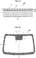
- FIG. 1 schematically illustrates an example of a cross-sectional view of said optical member according to an embodiment.
- An optical member 10A illustrated in FIG. 1 includes a transparent substrate 1 having a first main surface 1a and a second main surface 1b opposite from each other and an optical interference film 2.
- the entirety of the transparent substrate 1 satisfies the aforementioned condition (A) and the entirety of the optical interference film 2 is disposed on the entirety of the first main surface 1a of the transparent substrate 1.
- the optical member 10A including the first transparent substrate 1 and the optical interference film 2 satisfies the aforementioned condition (1).
- the optical interference film 2 is a multi-layer film including three layers with appended reference numbers 21, 22, and 23 that are stacked in this order on a side of the transparent substrate 1.
- any number of layers of an optical interference film that satisfies the condition (1) can be used in combination with a transparent substrate that satisfies the condition (A).
- optical member 10A examples are provided of a configuration where the optical interference film 2 is disposed on the second main surface 1b of the transparent substrate 1 and a configuration where the optical interference film 2 is disposed on both the first main surface 1a and the second main surface 1b of the transparent substrate 1. Since these examples also satisfy the condition (1), these variations are within the scope of said optical member.
- said optical member may be configured such that the optical interference film 2 is provided in only a predetermined region on the first main surface 1a of the transparent substrate 1. In such as case, it is acceptable as long as the condition (1) is satisfied in the region in which optical interference film 2 of the transparent substrate 1 is provided, and thus it is not necessary for the region where the interference film 2 is not provided to satisfy the condition (A). Furthermore, in the region where the interference film 2 is not provided, it is not necessary for the transparent substrate 1 to satisfy the condition (A) .
- the energy transmittance measured in compliance with JIS-R3106:1998 regarding the region of said optical member corresponding to a region other than the infrared high-transmittance region of the transparent substrate 1 preferably is 60% or less, more preferably is 50% or less, and particularly preferably is 45% or less, and even more particularly preferably is 40% or less.
- the region where laser light by the LiDAR laser passes through the transparent substrate 1 provided in a size equal to that of the window glass may have the configuration in which the optical interference film 2 is disposed on a main surface of the transparent substrate 1 satisfying the condition (1).
- the optical interference film 2 may be provided on the interior side of the vehicle-interior surface of the transparent substrate 1, on the vehicle-exterior surface of the transparent substrate 1, or on both the vehicle-interior surface and the vehicle-exterior surface of the transparent substrate 1.
- FIG. 1B is a plan view of an example of said optical member according to the embodiment for use with the windshield of a vehicle.
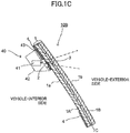
- FIG. 1C is a cross-sectional view obtained by cutting the windshield illustrated in FIG. 1B along X-X line.
- a windshield 10B that is said optical member includes the transparent substrate 1 and a blocking layer 4 that blocks visible light.
- the blocking layer 4 is provided on a vehicle-interior surface 1a of the transparent substrate 1 and is arranged along a periphery of the transparent substrate 1.
- the blocking layer 4 includes a protruding portion protruding in an in-plane direction (downward) from a central portion of a top side of the transparent substrate 1.
- the protruding portion has an opening 3 through which signals pass during transmission or reception of an infrared laser signals of a LiDAR sensor positioned substantially in the center portion.
- the optical interference film 2 is provided on the vehicle-interior surface 1a of the opening 3.
- FIG. 1B is a plan view of the windshield 10B as viewed from inside the vehicle.
- An attachment portion A of the LiDAR sensor is illustrated as a dashed line in FIG. 1B .
- the attachment portion A is located in the area surrounding the opening 3 of the blocking layer 4.
- a configuration of the LiDAR sensor 40 that is attachable to the windshield 10B is schematically illustrated by a dashed line in FIG. 1C .
- the LiDAR sensor 40 includes a LiDAR sensor main unit 41 and a housing 42 that accommodates the LiDAR sensor main unit 41.
- the housing 42 of the LiDAR sensor 40 is attached to the attachment portion A by adhering the housing 42 to the blocking layer 4 via an adhesive layer 43.
- the transparent substrate 1 of the windshield 10B is laminated glass.
- the laminated glass that is the transparent substrate 1 has a configuration in which a vehicle-interior glass sheet 1A and a vehicle-exterior glass sheet 1B are adhered together by an intermediate adhesive layer 1C.
- the laminated glass constituting the transparent substrate 1 is designed such that the region within the opening 3 satisfies the condition (A).
- the windshield 10B includes the optical interference film 2, corresponding to the opening 3, on a vehicle-interior surface 1a of the transparent substrate 1. By doing so, the opening 3 of the windshield 10B satisfies the aforementioned condition (1). Also, virtually no reduction in the sensing function occurs because reduction in the light amount over a wide range of incident angles is suppressed with respect to infrared laser light of the LiDAR sensor 40 that is transmitted and received via the opening 3.
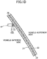
- FIG. 1D illustrates an example in which the optical member 10A illustrated in FIG. 1A is used as the cover member of the LiDAR sensor and the LiDAR sensor is attached to the vehicle-interior surface of the windshield.
- a windshield 20 has a configuration in which a vehicle-interior glass sheet 21 and a vehicle-exterior glass sheet 22 are adhered together by an intermediate adhesive layer 23.
- An optical member 10A is installed on the LiDAR sensor main unit 41 such that the optical interference film 2 is positioned on the side of the LiDAR sensor main unit 41.
- the LiDAR sensor main unit 41 together with the optical member 10A attached thereto is attached to the windshield 20 by adhering the transparent substrate 1 of the optical member 10A to the vehicle-interior surface of the windshield 20 (laminated glass 20) via an optical adhesive layer 5.
- the difference between a maximum value and a minimum value of plane stress in at least one or more locations within a region of 300 mm from the edge portion of the windshield 20 in a plane stress distribution of the surface of the windshield 20 preferably is 10 MPa or less, more preferably is 5 MPa or less, and most preferably is 1 MPa or less, from the standpoint of being able to reduce optical strain of the sensor attachment portion.
- the transparent substrate 1 has the first main surface 1a and the second main surface 1b opposing each other.
- the transparent substrate 1 includes at least one substance selected from glass, a glass ceramic, silicon, and sapphire and has a minimum transmittance in a wavelength band of 700 nm to 1800 nm (Hereinafter, also referred to as "T B700-1800 ".) that is 78% or more.
- T B700-1800 a wavelength band of 700 nm to 1800 nm
- the transparent substrate 1 does not need to satisfy the condition (A) in certain sections where appropriate, an example is described below in which the entirety of the transparent substrate 1 satisfies the condition (A).
- the T B700-1800 preferably of the transparent substrate preferably is 80% or more, more preferably is 85% or more, even more preferably is 88% or more, particularly preferably is 88.5% or more, even more particularly preferably is 89% or more, and most preferably is 89.5% or more.
- the transparent substrate has a minimum transmittance in the wavelength band of 800 nm to 1600 nm (Hereinafter, also referred to as "T B800-1600 ".) that is 79% or more. If the T B800-1600 of the transparent substrate is 79% or more, said optical member more sufficiently satisfies the condition of the T (1)min and ⁇ T (1) particularly in a case where there is a wavelength ⁇ s in a wavelength band of 800 nm to 1600 nm in (1).
- the T B800-1600 of the transparent substrate preferably is 81% or more, more preferably is 86% or more, even more preferably is 89% or more, particularly preferably is 90.5% or more, and most preferably is 91% or more.
- the transparent substrate 1 may be configured to include only one substance among glass, a glass ceramic, silicon, and sapphire, may be configured to include a composition of these substances, or may include other materials other than these substances.
- the transparent substrate 1 may be a single sheet or may be a stacked body.
- the transparent substrate 1 may be laminated glass having multiple glass sheets and a resin film that is disposed that is disposed between these glass sheets.
- the transparent substrate 1 is to include multiple layers such as laminated glass, when the laminated glass is configured, the transmittance of each layer is adjusted such that the T B700-1800 is 78% or more.
- the shape of the transparent substrate 1 may be that of a flat plate and may have a curvature along the entirety or along a portion of the transparent substrate 1.
- a flat transparent substrate is fabricated such that the configuration is the same as said transparent substrate 1, and then the optical characteristics such as the transmittance are measured.
- an optical member utilizing the transparent substrate 1 having a curvature an optical member that has the same configuration as said optical member and utilizes a flat transparent substrate is fabricated, and then the optical characteristics are measured.
- the thickness of the transparent substrate 1 can be appropriately adjusted for the intended usage within a range that satisfies the condition (A).
- the thickness of the transparent substrate 1, from the standpoint of strength and weight balance for ensuring safety preferably is 0.5 to 5 mm, more preferably is 1 to 5 mm, yet even more preferably is 1.5 to 4.5 mm, and particularly preferably is 2 to 4.3 mm.
- the combined thickness of the multiple glass sheets is to be regarded as the thickness of the transparent substrate 1.
- the Martens hardness that is to be measured at the surface of the transparent substrate 1 preferably is 4 N/mm 2 or more, more preferably is 4.5 N/mm 2 or more, and even more preferably is 5 N/mm 2 .
- the transparent substrate 1 preferably is made of amorphous material and even more preferably is made of glass. From a cost standpoint, it is particularly preferable that the transparent substrate 1 is made of amorphous glass that can be manufactured using the float technique.
- the amorphous glass is iron-containing glass containing, for example, soda lime glass, borosilicate glass, non-alkali glass, aluminosilicate glass, alkali-free aluminosilicate glass, and quartz glass, as the basic glass, in addition to iron.
- soda lime glass and borosilicate glass are both preferable but soda lime glass is particularly preferable.
- the content of iron (Fe) included in the iron-containing glass in terms of Fe 2 O 3 with respect to the basic glass of 100 mass% preferably is 1 to 500 mass ppm, more preferably is 50 to 300 mass ppm, and even more preferably is 80 to 180 mass ppm.
- the T B700-1800 of the transparent substrate can be easily adjusted to 78% or more.
- the temperature from the radiant heat during manufacturing can be retained, and thus the manufacturing characteristics can be maintained.
- the iron-containing glass has Fe content that is the aforementioned upper limit value or less, the T B700-1800 can be easily maintained at 78% or more.
- the iron-containing glass contains at least one metal oxide of 0.0001 to 2.5 mass% with respect to the basic glass of 100 mass%, the metal oxide being selected from the metal oxide group consisting of chromium oxide, cobalt oxide, manganese oxide, cerium oxide, copper oxide, and selenium oxide.
- the metal oxide being selected from the metal oxide group consisting of chromium oxide, cobalt oxide, manganese oxide, cerium oxide, copper oxide, and selenium oxide.
- One aforementioned metal oxide may be used alone or two or more metal oxides may be used in combination.
- the iron-containing glass further contains both oxides Cr 2 O 3 and Co
- Fe is 20 to 500 mass ppm
- Cr 2 O 3 is 0.0015 to 1 mass%
- cobalt oxide is 0.0001 to 1 mass% with respect to the basic glass of 100 mass%.
- the content of the aforementioned metal oxide with respect to the basic glass 100 mass% more preferably is 1 to 200 mass ppm, even more preferably is 2 to 100 mass ppm, and most preferably is 3 to 70 mass ppm.
- the value of the Redox [ferrous iron (Fe 2+ ) in terms of [Fe 2 O 3 ]/ [ total of (Fe 2+ + Fe 3+ ) obtained by [ferrous iron (Fe 2+ )+ ferric iron (Fe 3+ ) in terms of Fe 2 O 3 ]
- the value of the Redox [ferrous iron (Fe 2+ ) in terms of [Fe 2 O 3 ]/ [ total of (Fe 2+ + Fe 3+ ) obtained by [ferrous iron (Fe 2+ )+ ferric iron (Fe 3+ ) in terms of Fe 2 O 3 ]
- the T B700-1800 improves while maintain the manufacturing characteristics.
- a total of Al 2 O 3 , MgO, and CaO preferably is 0.1 to 30 mass% denoted as mass% in terms of oxides. Said content more preferably is 5 to 25 mass% and even more preferably is 10 to 20 mass%. If the total content of Al 2 O 3 , MgO, and CaO is within one of the aforementioned ranges, the water resistance, acid resistance, and the weather resistance are good.
- the “%" in the composition of the basic glass is denoted as mass% in terms of oxides, unless otherwise noted.
- the ratio expressed by B 2 O 3 / (B 2 O 3 + R 2 O) denoted as mass% in terms of oxides preferably is 0.3 or less, more preferably is 0.2 or less, and particularly preferably is 0.05 or less.
- R 2 O denotes Na 2 O+K 2 O.
- composition in terms of mass% as the composition of the basic glass used in iron-containing glass is as follows:
- SiO 2 is a component for forming a structure of glass. If the content of SiO 2 is 55% or more, the heat resistance, chemical durability, and weather resistance are good. If the content of SiO 2 is 85% or less, meltability is good because the viscosity at the time of glass melting does not become excessively high.
- the content of SiO 2 is preferably 60% or more.
- the content of SiO 2 is preferably 78% or less, and more preferably 75% or less.
- Al 2 O 3 is not an essential component, when there is Al 2 O 3 is included, the weather resistance, heat resistance, and chemical durability are good, and Young's modulus increases. If the content of Al 2 O 3 is 30% or less, meltability is good because the viscosity at the time of glass melting does not become excessively high, and devitrification hardly takes place.
- the content of Al 2 O 3 preferably is 18% or less and more preferably is 6% or less.
- B 2 O 3 is not an essential component, when B 2 O 3 is included, meltability is good because the viscosity at the time of glass melting does not become excessively high, and devitrification hardly takes place. If the content of B 2 O 3 is 20% or less, the glass-transition temperature can be increased, and Young's modulus increases.
- the content of B 2 O 3 preferably is 18% or less and is more preferably 4% or less.
- CaO is not an essential component
- meltability is good because the viscosity at the time of glass melting does not become excessively high, and weather resistance improves. If the content of CaO is 20% or less, devitrification hardly takes place.
- the content of CaO preferably is 15% or less.
- MgO is not an essential component
- meltability is good because the viscosity at the time of glass melting does not become excessively high, weather resistance improves, and Young's modulus increases.
- the content of MgO is 15% or less, devitrification hardly takes place.
- the content of MgO is 10% or less.
- BaO is not an essential component, when BaO is included, meltability is good because the viscosity at the time of glass melting does not become excessively high, and weather resistance improves. If the content of BaO is 20% or less, devitrification hardly takes place.
- the content of BaO preferably is 10% or less and more preferably is 5% or less.
- the melting temperature decreases. If the content of Na 2 O is 25% or less, devitrification hardly takes place, and the forming temperature decreases making bend-forming easy.
- the content of Na 2 O is 5% to 20%. More preferably, the content of Na 2 O is 10% to 17%.
- K 2 O is not an essential component
- the melting temperature decreases. If the content of K 2 O is 20% or less, devitrification hardly takes place.
- the content of K 2 O preferably is 10% or less or more preferably is 5% or less.
- the iron-containing glass may be configured to contain components selected from the group, for example, consisting of SnO 2 , SO 3 , and Cl, as a clarifying agent.
- the iron-containing glass may be configured to contain, for example, ZnO, Li 2 O, WO 3 , Nb 2 O 5 , V 2 O 5 , Bi 2 O 3 , MoO 3 , P 2 O 5 , Ga 2 O 3 , I 2 O 5 , In 2 O 3 , Ge 2 O 5 , and the like.
- ZnO Li 2 O, WO 3 , Nb 2 O 5 , V 2 O 5 , Bi 2 O 3 , MoO 3 , P 2 O 5 , Ga 2 O 3 , I 2 O 5 , In 2 O 3 , Ge 2 O 5 , and the like.
- the iron-containing glass As a composition that is substantially free of As 2 O 3 and Sb 2 O 3 . Also, for the purpose of stably performing float forming, it is preferable to keep the iron-containing glass a composition that is substantially free of ZnO.
- the transparent substrate made of glass (Hereinafter, referred to as "glass substrate”.) that is used for said optical member is obtained by appropriately blending various raw materials so that the composition is within a desired range, performing heating and melting, then performing defoaming, stirring, and the like to make the composition uniform, and then forming the composition into a sheet or the like by a well-known method such as the float method, the down-draw method, press method, or the roll-out method or forming the composition into block shape by casting, and after annealing, finally forming the mold into a sheet shape.
- a well-known method such as the float method, the down-draw method, press method, or the roll-out method or forming the composition into block shape by casting, and after annealing, finally forming the mold into a sheet shape.
- the glass substrate it is preferable to use a glass sheet formed by the float method, for example. Also, it is preferable that the glass substrate goes through a toughening process by being thermally tempered (physically tempered) or chemically tempered. By going through this toughening process, a compressive stress layer is formed on the surface of the glass substrate, and this improves the strength against scratches and physical impact.
- the linear expansion coefficient of glass constituting the glass substrate preferably is 60 ⁇ 10 -7 /°C, more preferably is 71 ⁇ 10 -7 /°C, even more preferably is 75 ⁇ 10 -7 /°C, and particularly preferably is 85 ⁇ 10 -7 /°C.
- the linear expansion coefficient of glass preferably is 100 ⁇ 10 -6 /°C, more preferably is 95 ⁇ 10 -6 /°C, and particular preferably is 90 ⁇ 10 -6 /°C.
- the linear expansion coefficient of glass in the present specification is an average linear expansion coefficient in the range of 50°C to 350°C.
- the surface compressive stress (CS) of the physically-tempered glass substrate is 10 MPa or more, for example.
- the surface compressive stress more preferably is 30 MPa or more, even more preferably is 50 MPa or more, and particularly preferably is 100 MPa.
- the surface compressive stress (CS) is measured by using the following procedure.
- a disc of which all the surfaces are mirror surfaces is fabricated from the glass substrate whose compressive stress layer has not yet been formed.
- a photoelastic constant is obtained by the disk compression method.
- the cut surface is optically polished.
- retardation is measured by using a birefringence measuring device. Further, the retardation value measured is divided by the photoelastic constant and the glass substrate thickness to thereby obtain the generated stress (surface compressive stress (CS) of the surface).
- CS surface compressive stress
- the glass substrate to be used in said optical member is a toughened glass sheet
- the glass substrate to be used in said optical member is laminated glass
- the size of the glass substrate to be used in said optical member can be appropriately adjusted for the intended usage.
- a glass sheet obtained by, for example, the float method and by being cut into a predetermined size may be used.
- the edge surfaces connecting the first main surface and the second main surface of the glass substrate together are chamfered for the purpose of, for example, preventing breaks from occurring at the edge portions or in the vicinity of the edge portions.
- the transparent substrate to be used in said optical member is laminated glass as illustrated in FIG. 1B and FIG. 1C
- the transparent substrate may satisfy the condition (A) by configuring the vehicle-interior glass sheet 1A or the vehicle-exterior glass sheet 1B with the aforementioned iron-containing glass. More preferably, the transparent substrate satisfies the condition (A) by configuring both the vehicle-interior glass sheet 1A and the vehicle-exterior glass sheet 1B with the aforementioned iron-containing glass.
- an intermediate adhesive layer containing, as a main component, a thermoplastic resin such as polyvinyl butyral (PVB), ethylene vinyl acetate (EVA), or cyclo olefin polymer (COP) used in typical laminated glass can be used as the intermediate adhesive layer 1C without particular limitation.
- a thermoplastic resin such as polyvinyl butyral (PVB), ethylene vinyl acetate (EVA), or cyclo olefin polymer (COP) used in typical laminated glass
- PVB polyvinyl butyral
- EVA ethylene vinyl acetate
- COP cyclo olefin polymer
- a near-infrared light-transmissive resin film may be provided between the intermediate adhesive layer and the glass substrate.
- the near-infrared light-transmissive resin film is formed as a coating film on the main surface, of the vehicle-interior glass or the vehicle-exterior glass, facing the intermediate adhesive layer.
- the optical interference film 2 is formed on the first main surface 1a of the transparent substrate 1 and functions such that the obtained optical member 10A satisfies the condition (1).
- the optical interference film 2 for example, in the obtained optical member 10A, causes the reflectance to decrease more than in a case where the transparent substrate is used alone, with respect to light of the wavelength ⁇ s in an incidence angle range of 0 degrees to 60 degrees, and thus functions such that the optical member 10A satisfies the condition (1). It is preferable that the optical interference film 2 functions such that the obtained optical member 10A further satisfies one or more conditions selected from the conditions (2), (3), and (4).
- the film 2 may also function to impart visible light blocking, ultraviolet light blocking, antifouling characteristics, dust resistance, for example, and other functions that, for example, improve durability.
- the optical interference film 2 may be configured so as to be provided on only the first main surface 1a of the transparent substrate 1 such in the optical member 10A illustrated in FIG. 1 , may be configured so as to be provided on only the second main surface 1b of the transparent substrate 1, or may be configured so as to be provided on both the first main surface 1a and the second main surface 1b of the transparent substrate 1.
- the optical interference film 2 there is no difference in the design of the optical interference film 2 between a case where the optical interference film 2 is provided on only the first main surface 1a of the transparent substrate 1 and a case where the optical interference film 2 is provided on only the second main surface 1b of the transparent substrate 1.
- the optical member obtained by the two optical interference films used in combination satisfies condition (1), and more preferably, each of the optical interference films is designed so as to satisfy one or more conditions selected from the conditions (2), (3), and (4).
- the optical interference film is provided on both main surfaces of the transparent substrate, it is not necessary for the optical member using only one of either optical interference film to satisfy the condition (1).
- the optical member using only one preferably satisfies the condition (1) and preferably, and an optical interference film that satisfies the conditions (2), (3), and (4) is provided on both main surfaces of the transparent substrate.
- the T (1)min and ⁇ T (1) improves more whereas the light loss in (2) is apt to increase in comparison to the case where only one of either optical interference film is used.
- the configuration of the optical interference film may be appropriately selected in accordance with the optical characteristics needed in the optical member.
- the optical interference film 2 may be a single layer film constituting only a single layer or a multilayer film having two or more stacked layers, the multilayer film is preferable.
- the multilayer preferably has two or more layers including a high refractive index layer and a low refractive index layer. From the standpoint of manufacturing cost and layer thinning, the total number of layers in the multilayer film preferably is ten or less layers and more particularly preferably is four or less layers.
- the low refractive index layer and the high refractive index layer preferably are stacked upon each other adjacently.
- the low refractive index layer is made of a material with a low refractive index (low refractive index material) whereas the high refractive index layer is made of a material with a high refractive index (high refractive index material).
- the difference in the refractive index between the low refractive index layer and the high refractive index layer that is, the difference in the refractive index between the low refractive index material and the high refractive index material may be greater than zero and preferably is 0.1 or more.
- the refractive indexes of the optical thin-films constituting the optical interference film described in the present specification signify the refractive indexes of all the respective materials in the light of the predetermined wavelength ⁇ s .
- the multilayer film that includes the low refractive index layer and the high refractive index layer may further include an intermediate refractive index layer.
- the intermediate refractive index layer includes an intermediate refractive index layer that has a refractive index that is higher than the refractive index of the low refractive index layer and lower than the refractive index of the high refractive index layer.
- the multilayer film includes the low refractive index layer, the high refractive index layer, and the intermediate refractive index layer
- the low refractive index layer and the high refractive index layer are stacked upon each other adjacently and the intermediate refractive index layer is stacked so as to contact a main surface, of the high refractive index layer, opposite to the other main surface, of the high refractive index layer, in contact with the low refractive index layer.
- the intermediate refractive index layer is stacked so as to contact a main surface, of the low refractive index layer, opposite to the other main surface, of the low refractive index layer, in contact with the high refractive index layer.
- the geometric thickness of each of the layers in the case where the optical interference film 2 is a multilayer film, may be appropriately set to suit the materials to be used and the optical characteristics needed.
- the optical interference film 2 since the wavelength band of the infrared band is a key concern, it is preferable that at least one layer among the layers constituting the optical interference film 2 has a geometric thickness of 50 nm or more. Assuming that at least one of the layers has a thickness of 50 nm or more, the geometric thicknesses of each layer (the per-layer film thickness) constituting the optical interference film 2 may be set to a 5 nm to 500 nm.
- the optical interference film 2 transmittance reduction due to optical scattering can be suppressed by setting the upper limit of the per-layer film thickness to 500 nm. Also, by setting the per-layer film thickness of the optical interference film 2 to 5 nm or more, the optical interference film 2, in actuality, exists as a continuous film, enabling the functions to be sufficiently exhibited.
- the geometric total film thickness of the optical interference film 2 preferably is 300 nm, more preferably is 400 nm or more, and even more preferably is 500 nm or more.
- the geometric total film thickness of the optical interference film 2 preferably is 2000 nm or less, more preferably is 1500 nm or less, and even more preferably is 1200 nm or less.
- the individual optical interference films may each have substantially the same configuration as that described above.
- the upper limit of the geometric total film thickness of the optical interference is preferably 4000 nm, with 4000 nm being the combined total of the two optical interference films.
- the optical interference film in the optical member 10A illustrated in FIG. 1 is an example of an optical interference film 2 having a configuration in which an intermediate refractive index layer, a low refractive index layer, and a high refractive index layer are stacked upon one another.
- the optical interference film 2 has a configuration in which an intermediate refractive index layer 21, a high refractive index layer 22, and a low refractive index layer 23 are sequentially stacked in this order on the first main surface 1a side of the transparent substrate 1.
- the refractive index of the low refractive index material constituting the low refractive index layer 23 preferably is 1.35 or more and less than 1.55.
- a material as the low refractive index material include a material mainly composed of a low refractive index substance such as silicon oxide, magnesium fluoride, and the like.
- the term "mainly composed of a substance" in each refractive index layer means that said substance is contained at 50 mol% or more.
- the low refractive index material has a low refractive index and preferably is mainly composed of at least one type of a low refractive index substance as long as the refractive index is adjusted to be within the aforementioned range, and furthermore may contain an intermediate refractive index substance and a high refractive index substance.
- the low refractive index material preferably includes only a low refractive index substance and more preferably includes only one type of a low refractive index substance. From the standpoint of reproducibility, stability, and economic efficiency in film formation, it is preferable that silicon oxide is used as the low refractive index substance.
- the refractive index of a high refractive index material constituting the high refractive index layer 22 is preferably 1.90 to 5.00.
- a material as the high refractive index material include a material mainly composed of a high refractive index substance such as silicon nitride, silicon oxynitride, aluminum nitride, aluminum oxynitride, zirconium oxide, tin oxide, cerium oxide, silicon, copper oxide, germanium, titanium oxide, niobium oxide, tantalum oxide, and the like.
- the high refractive index material has a high refractive index and preferably is mainly composed of at least one type of a high refractive index substance as long as the refractive index is adjusted to be within the aforementioned range, and furthermore may contain a low refractive index substance and an intermediate refractive index substance.
- the high refractive index material preferably includes only a high refractive index substance.
- silicon nitride, silicon oxynitride, aluminum nitride, aluminum oxynitride, zirconium oxide, titanium oxide, niobium oxide, tin oxide, cerium oxide, silicon, and copper oxide are preferable because the desired optical characteristics can be obtained in a case where a multilayer film is used.
- silicon nitride, silicon oxynitride, aluminum nitride, aluminum oxynitride, zirconium oxide, tin oxide, and cerium oxide are preferable, silicon nitride, zirconium oxide, and aluminum nitride are more preferable, and silicon nitride is particularly preferable.
- the transparent substrate 1 having a curvature may include the optical interference film 2 that is a multilayer film.
- the optical interference film may be stacked onto the glass sheet after the glass sheet is bent to a predetermined shape.
- the glass sheet may be bent to a predetermined shape after stacking the optical interference film onto the glass sheet. It is more preferable to bend the glass sheet after stacking the optical interference film onto the glass sheet because this way the optical interference film can be stacked on a flat surface.
- the glass sheet is heated to the vicinity of the softening point in order to bend the glass sheet, it is important for the optical interface film to be such that not quality does not change due to high temperatures.
- the refractive index of the intermediate refractive index material constituting the intermediate refractive index layer 21 is preferably 1.55 or more and less than 1.90.
- a material as the intermediate refractive index material include a material mainly composed of an intermediate refractive index substance such as a mixture of aluminum oxide, silicon oxynitride, aluminum oxynitride, silicon oxide, and zirconium oxide, a mixture of silicon oxide and aluminum nitride, and the like.
- the intermediate refractive index material is a refractive index that is between the refractive index of the high refractive index material and the refractive index of the low refractive index material, preferably is mainly composed of at least one type of an intermediate refractive index substance as long as the refractive index is adjusted to be within the aforementioned range, and furthermore may contain a low refractive index substance and a high refractive index substance.
- a mixture of silicon oxide and aluminum nitride is a preferable example of the intermediate refractive index substance.
- the intermediate refractive index material preferably includes only an intermediate refractive index substance and more preferably includes only one type of an intermediate refractive index substance.
- the intermediate refractive index substance aluminum oxide, silicon oxynitride, and aluminum oxynitride are preferable and a mixture of aluminum oxide, zirconium oxide, and silicon oxide are particularly preferable because the desired optical characteristics and hardness can be obtained when made into a multilayer film.
- metal nitrides, oxides, and oxynitrides notated as metal name + nitride, metal name + oxide, and metal name + oxynitride, unless otherwise noted, indicate nitrides, oxides, and oxynitrides of a stochiometric composition ratio or a non-stochiometric composition ratio.
- silicon nitride may be described as SiN x .
- the geometric thickness of the intermediate refractive index layer 21, the high refractive index layer 22, and the low refractive index layer 23 in the optical interference film 2 can be set appropriately to suit the materials constituting the respective layers and the needed optical characteristics.
- the following two combinations (i) and (ii) are preferable as optical thicknesses for the respective layers in a case where the intermediate refractive index layer 21, the high refractive index layer 22, and the low refractive index layer 23 are made of aluminum oxide, silicon nitride, and silicon oxide, respectively.
- t 21 indicates the optical thicknesses of the intermediate refractive index layer 21 made of aluminum oxide
- t 22 indicates the optical thicknesses of the high refractive index layer 22 made of silicon nitride
- t 23 indicates the optical thicknesses of the low refractive index layer 23 made of silicon oxide.
- optical thicknesses may be widths that are ⁇ 5% of these values. The same applies in the example indicated below.
- the film configuration that achieves a high transmittance over a wide range in the infrared band, for example.
- the intermediate refractive index layer 21, the high refractive index layer 22, and the low refractive index layer 23 are composed, respectively, of aluminum oxide, silicon nitride, and silicon oxide
- t 22 0.663 ⁇ s
- t 23 0.358 ⁇ s , as the optical thicknesses.
- the difference between the maximum value and the minimum value of the transmittance within these angles of incidence is 8% or less.
- the optical interference film 2 As another example of the optical interference film 2, an example is provided where a high refractive index layer and a low refractive index layer are stacked upon each other, one layer each for a total of two layers, in this order from the first main surface 1a side of the transparent substrate 1.
- the thicknesses of the respective layers are, where the high refractive index layer is made of copper oxide and the low refractive index layer is made of silicon oxide, 0.466 ⁇ s and 0.155 ⁇ s as the optical thicknesses.
- the thicknesses of the respective layers are 0.492 ⁇ s and 0.148 ⁇ s as the optical thicknesses.
- the thicknesses of the respective layers are, where the high refractive index layers are made of copper and the low refractive index layers are made of silicon oxide, are 0.517 ⁇ s , 0.269 ⁇ s , 0.467 ⁇ s , and 0.142 ⁇ s as the optical thicknesses in order from the first main surface 1a side of the transparent substrate 1.
- the thicknesses of the respective layers are 1.023 ⁇ s , 0.296 ⁇ s , 0.482 ⁇ s , and 0.122 ⁇ s as the optical thicknesses.
- the maximum value with the angle of incidence at 25 degrees or more, more preferable to obtain the minimum value at 30 degrees or more, and most preferable to obtain the maximum value at 35 degrees or more, after having changed the angle of incidence between light of the sensor wavelength ⁇ s and an optical article from 0 degrees through to 60 degrees.
- the range regarded as preferable above is preferable because the transmittance in the sensor wavelength ⁇ s is high.
- the stacking structure such as the number of layers, the materials constituting the layers, the layer-stacking order, and the thickness of the layers can be appropriate changed to suit the needed optical characteristics.
- the aforementioned optical interference film with one of the two-layer to four-layer configurations provided on one of the main surfaces of the transparent substrate is provided on both main surfaces.
- the configurations of the optical interference films provided on both main surfaces may be the same or more be different from each other.
- the optical interference film 2 can be formed on the transparent substrate 1 by a publicly-known formation method. Specifically, formation is performed by using a film formation such as a thermal evaporation method, a sputtering method, an ion assisted deposition (IAD) method, and the like. In particular, in a case where a film with high scratch resistance is to be formed as the optical interference film 2, it is preferable to use a sputter method or an ion assistance deposition method so as to obtain a dense film.
- a film formation such as a thermal evaporation method, a sputtering method, an ion assisted deposition (IAD) method, and the like.
- IAD ion assisted deposition
- the optical member 10A composed of the transparent substrate 1 and the optical interference film 2 is described with reference to FIG. 1A to FIG. 1D .
- the design of the transparent substrate 1 and the optical interference film 2 can be changed to the extent that the effects of the present disclosure are not lessened.
- components other than the transparent substrate 1 and the optical interference film 2 may be optionally included in the optical member 10A to the extent that the effects of the present disclosure are not lessened.
- components that may be optionally included include a coating that imparts a water repellant function, a hydrophilic function, a fogging prevention function, and the like, and a low thermal emissivity coating, an infrared light shielding coating, visible light shielding coating, a conductive coating, and the like.
- the Martens hardness to be measured at the surface of the optical interference film in said optical member preferably is 4 N/mm 2 , more preferably is 4.5 N/mm 2 , and even more preferably is 5 N/mm 2 in order to satisfy the condition (4) specifying that the Martens hardness to be measured at the surface of the optical interference film is harder than the Martens hardness to be measured at the surface of the transparent substrate 1.
- the value of this preferred Martens hardness can be achieved by including materials, regarded as preferable in terms of hardness described above, in the high refractive index material of the optical interference film.
- the visible light transmittance in a wavelength band of 380 nm to 780 nm measured at an incidence angle of 0 degrees preferably is 30% or less, more preferably is 20% or less, and particularly preferable is 10% or less, from the standpoint of design and safety.
- the visible light reflectance of the aforementioned wavelength band to be measured at an incidence angle of 5 degrees at the surface of the optical interference film preferably is 60% or more and more preferably is 70% or more, from the standpoint of maintaining a sense of unity in the external appearance of the vehicle.
- the visible light reflectance in a case where, for example, said optical member is to be attached to the body of a vehicle that is a matte color type preferably is 8% or less and more preferably is 5% or less, from the standpoint of not spoiling the external appearance of the vehicle.
- the wavefront aberration at the wavelength ⁇ s is 1.0 ⁇ RMS or less.
- the wavefront aberration can be calculated based on the measurement results of a surface shape by a surface shape measuring device such as a laser interferometry-type flatness measurer (for example, Verifire and Mark IV manufactured by Zygo; G310S manufactured by Fujinon, and Fiat Master manufactured by TOEI), a laser displacement meter, an ultrasonic displacement meter, a contact-type displacement meter, and the like.
- the remainder excluding the tilting component from the results obtained by the various types of measuring devices is the surface shape whereas the wavefront aberration is the difference between the maximum value and the minimum value of the surface shape.
- the wavefront aberration at the wavelength ⁇ s preferably is 0.9 ⁇ RMS or less, more preferably is 0.6 ⁇ RMS or less, and even more preferably is 0.3 ⁇ RMS or less.
- the transmittance and reflectance as well as the transmitted colors and reflected colors of the visible light region are adjusted such that there is harmony between the external appearance and the surroundings to suit the usage environment and the components. Therefore, a layer of, for example organic ink or inorganic ink may be used in conjunction with the optical interference film as an element other than the optical interference film to be used. In such as case, it may be necessary for the material of the ink to be transparent in the near-infrared band in order to maintain the transmittance in the near-infrared band.
- the water contact angle to be measured in said optical member at the surface of the optical interference film preferably is 90 degrees or more and more preferably is 100 degrees or more, from the standpoint of preventing a decrease in transmittance due to infrared absorption of water.
- the water contact angle to be measured at the surface of the optical interference film preferably is 20 degrees or less and more preferably is 10 degrees or less, from the standpoint of ensuring visibility.
- Said optical member has a high transmittance over a wide range of incident angles with respect to infrared light.
- infrared light used for sensing by the LiDAR sensor passes through unhampered over a wide range of incident angles.
- methods for attaching said optical member to a LiDAR sensor as the cover member include a method in which direct affixing is performed via an adhesive through which infrared light passes, a method involving attachment to the housing of a LiDAR sensor, and the like.
- the optical interference member is disposed so as to be on the LiDAR sensor-side.
- the LiDAR sensor is mounted and used in, for example, a transport vehicle such as a train, an automobile, a boat, and an aerial vehicle.
- Said optical member is particularly suitable as a cover member of the LiDAR sensor mounted in an automobile.
- the LiDAR sensor is attached to, for example, a bumper, a side mirror, a pillar, a rear portion of a vehicle rearview mirror, and the like.
- Said optical member is advantageous in that the strength and design can be adjusted in accordance with the site of application.
- the optical member of the present disclosure is used as window glass in a case where the LiDAR sensor is mounted on the interior of the vehicle, a decrease in sensing caused by using the window glass as an intermediary can be suppressed.
- the optical member of the present disclosure is used as window glass of an automobile, it is also applicable as the windshield, rear window, side glass, roof glass, and the like.
- Optical members in which the configuration of the optical interference film in the configuration illustrated in FIG. 1A is appropriately changed in each of the examples, were fabricated and evaluated.
- Examples 1 to 15 and 23 to 29 are embodiment examples, whereas Examples 16 to 22 are comparative examples.
- Table 1 illustrates the composition, optical characteristics, and Martens hardness of the transparent substrates. Five types of glass substrates were used. The optical characteristics and Martens hardness of the glass substrates were measured using a method that is substantially the same as the method useable for evaluation of the optical members described further below.
- Glass substrates GA, GB, GC, and GE are glass substrates that satisfy the condition (A), whereas a glass substrate GD has a T B700-1800 of less than 78%, and thus does not satisfy the condition (A).
- "Co" in the composition of the glass substrate GA indicates that the composition is cobalt (Co) oxide.
- Table 2 illustrates configurations of eleven types of optical interference films IA to IK used in the present embodiment examples, and specifically indicates the number of layers, the stacking order the composition of materials of each layer, and the geometric thickness.
- the optical members according to Examples 1 to 15 and Examples 20 to 29 were fabricated by forming one optical interference film among the eleven types of optical interference films IA to IK illustrated in Table 2, using the method below, onto only the first main surface or onto both the first main surface and the second main surface of the transparent substrate in accordance with the combinations illustrated in Table 3 and Table 4.
- the optical interference films are designed with the wavelength As set to 940 nm.
- the optical interference films are designed with the wavelength ⁇ s set to 1550 nm.
- the optical interference film is designed with the two wavelengths ⁇ s set to 940 nm and 1550 nm.
- the optical interference film is designed with the wavelength ⁇ s set to 940 nm.
- the optical members according to Examples 16 to 19 among the comparative examples are not provided with an optical interference film.
- Table 2 illustrates a layer configuration of the optical interference film as the first layer, the second layer, the third layer, and the fourth layer in this order on the side of the transparent substrate.
- a cell with a diagonal line indicates that there is no layer.
- Optical Interference Film Abbreviation Bottom Layer First Layer Second Layer Third Layer Fourth Layer Number of Layers Film Thickness [nm] IA Transparent Substrate Al 2 O 3 199 nm SiN x 76 nm SiO 2 220 nm 3 495 IB Al 2 O 3 330 nm SiN x 130 nm SiO 2 363 nm 3 823 IC Al 2 O 3 147 nm SiN x 65 nm SiO 2 200 nm 3 412 ID Al 2 O 3 213 nm SiN x 81 nm SiO 2 234 nm 3 528 IE CuO 282 nm SiO 2 165 nm 2 447 IF Si 199 nm SiO 2 157 .
- the formation of the optical interference film was performed by using a sputtering device (RAS1100BII manufactured by Shincron).
- the optical interference films IA to ID and the optical interference films II and IK were configured with an aluminum oxide layer that is the intermediate refractive index layer as the first layer, a silicon nitride layer that is the high refractive index layer as the second layer, and a silicon oxide layer that is the low refractive index layer as the third layer.
- the optical interference films IA to ID and optical interference films II and IK are formed using substantially the same method.
- the aluminum oxide layer that is the intermediate refractive index layer For forming the aluminum oxide layer that is the intermediate refractive index layer, an Al target was used, argon was used as the discharge gas in the film formation chamber, and oxygen was used as the discharge gas of the reaction chamber. The pressure during film formation was 0.15 Pa.
- the geometric thicknesses of the aluminum oxide layer in the optical interference films IA to ID and the optical interference films II and IK were adjusted such that the respective thicknesses are illustrated in Table 2 as "nm".
- the silicon nitride layer that is the high refractive index layer For forming the silicon nitride layer that is the high refractive index layer, an Si target was used, argon was used as the discharge gas of the reaction chamber, and nitride was used as the discharge gas of the reaction chamber. The pressure during film formation was 0.15 Pa.
- the geometric thicknesses of the silicon nitride layer in the optical interference films 1A to ID and the optical interference films II and IK were adjusted such that the respective thicknesses are illustrated in Table 2 as "nm".
- the silicon oxide layer that is the low refractive index layer For forming the silicon oxide layer that is the low refractive index layer, an Si target was used, argon was used as the discharge gas in the film formation chamber, and oxygen was used as the gas of the reaction chamber. The pressure during film formation was 0.15 Pa.
- the geometric thicknesses of the silicon oxide layer in the optical interference films IA to ID and the optical interference films II and IK were adjusted such that the respective thicknesses are illustrated in Table 2 as "nm".
- the high refractive index materials namely, a titanium oxide layer containing zirconium oxide, a titanium oxide layer, a niobium oxide layer, and a tantalum oxide layer
- a titanium target containing 50 mol% of zirconium, a titanium target, a niobium target, and a tantalum target oxide layer were used respectively, whereas argon was used as the discharge gas of the film formation chamber, and oxygen was used as the discharge gas of the reaction chamber.
- the pressure during film formation was 0.15 Pa.
- the geometric thicknesses of the respective high refractive index layers in the optical interference films IL to IP were adjusted such that the respective thicknesses are illustrated in Table 2 as "nm".
- the copper oxide layer that is the high refractive index layer and the silicon oxide layer that is the low refractive index layer were, in this order on the side of the glass substrate, respectively formed once for each layer and twice for each layer alternatingly, such that the geometric thicknesses of the respective layers are the values illustrated in Table 2.
- the copper oxide layer that is the high refractive index layer For forming the copper oxide layer that is the high refractive index layer, a Cu target was used, argon was used as the discharge gas of the film formation chamber, and oxygen was used as the discharge gas of the reaction chamber. The pressure during film formation was 0.15 Pa.
- the geometric thicknesses of the copper oxide layer in the optical interference films IE and IG were adjusted such that the respective thicknesses are illustrated in Table 2 as "nm".
- the formation of the silicon oxide layer that is the low refractive index layer was performed in substantially the same manner as described above. In the optical interference film IG, the formation of the copper oxide layer and the formation of the silicon oxide layer were performed repeatedly to form the optical interference film of the configuration illustrated in Table 2.
- the silicon layer that is the high refractive index layer and the silicon oxide layer that is the low refractive index layer were, in this order on the side of the glass substrate, respectively formed once for each layer and twice for each layer alternatingly, such that the geometric thicknesses of the respective layers are the values as illustrated in Table 2.
- the silicon layer that is the high refractive index layer For forming the silicon layer that is the high refractive index layer, a Si target was used, whereas argon was used as the discharge gas in the film formation chamber and the reaction chamber. The pressure during film formation was 0.15 Pa.
- the geometric thicknesses of the silicon layer in the optical interference film IF and the optical interference film IH were adjusted such that the respective thicknesses are illustrated in Table 2 as "nm".
- the formation of the silicon oxide layer that is the low refractive index layer was performed in substantially the same manner as described above. In the optical interference film IH, the formation of the silicon oxide layer and the formation of the silicon layer were performed repeatedly to form the optical interference film of the configuration illustrated in Table 2.
- the silicon oxynitride layer that is the high refractive index layer and the silicon oxide layer that is the low refractive index layer were formed in this order onto the side of the glass substrate such that the geometric thicknesses of the respective layers are values as illustrated in Table 2.
- the silicon oxynitride that is the high refractive index layer an Si target was used, whereas argon was used as the discharge gas of the film formation chamber and a mixture of gas with a volume ratio of oxygen to nitrogen of 1:10 was used. The pressure during film formation was 0.15 Pa.
- the geometric thicknesses of the silicon layers in the optical interference film IJ were adjusted such that the respective geometrical thicknesses are in [nm] as illustrated in Table 2.
- the silicon oxide layer that is the low refractive index layer is formed in substantially the same manner as described above.
- Table 3 and Table 4 for each embodiment example illustrate the abbreviations of glass substrates used and abbreviations of the optical interference film(s) formed on one or both main surfaces of the glass substrate along with the evaluation results described below.
- the first main surface 1a of the transparent substrate (glass substrate) is illustrated as the first optical interference film and the optical interference film formed on the second main surface 1b is illustrated as the second optical interference film.
- the symbol "-" indicates that no optical interference film was formed.
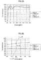
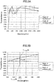
- FIG. 2A and FIG. 3A illustrate spectral transmittance curves in the incidence angle of 0 degrees and in the incidence angle of 60 degrees of the optical member of Example 1 and the optical member of Example 2, respectively.
- Transmittance was measured in 5 degree increments from an incidence angle of 0 degrees through to 60 degrees for a total of 13 times in the wavelength band of 200 nm to 1800 nm. Based on this 13-point transmittance curve, a minimum value and a maximum value of transmittance at the wavelength ⁇ s were obtained. Table 3 and Table 4 illustrate the minimum value and the maximum value of the transmittance as the incidence angles ( ⁇ 2 , ⁇ 1 ) at that time and T (1)min ( ⁇ 2 ), T (1)max ( ⁇ 1 ) and the difference between these as ⁇ T (1) .
- the T (1)min is the transmittance at the incidence angle of 60 degrees, that is, in a case where the minimum value is obtained when ⁇ 2 is 60 degrees
- the notation of the angle with the brackets is omitted.
- the T (1)max is the transmittance at the incidence angle of 0 degrees, that is, in a case where the maximum value is obtained when ⁇ 1 is 0 degrees
- the notation of the angle with the brackets is omitted.
- FIG. 2B and FIG. 3B illustrate the spectral transmittance curves, in vicinity of a set wavelength ⁇ s (940 nm) at an incidence angle of 0 degrees and an incidence angle of 60 degrees of the optical member according to Example 1 and the optical member according to Example 2, respectively.
- the T (1)min and the T (1)max positions and ⁇ T (1) are illustrated in the spectral transmittance curves.
- T (1)min is the transmittance at the incidence angle of 60 degrees
- T (1)max is the transmittance at the incidence angle of 0 degrees
- the notations in the spectral transmittance curves for the incidence angles of 5 degrees to 55 degrees are omitted.
- the transmittance and reflectance at an incidence angle of 5 degrees were measured using a spectrophotometer and an absolute reflectance device.
- the value obtained by subtracting the reflectance and the transmittance from 100% is regarded as the light loss.
- Example 1 to Example 15 and Example 20 to Example 22 the optical characteristics corresponding to the wavelength ⁇ s set for design of the optical interference film are illustrated in Table 3 and Table 4.
- the optical characteristics likewise are evaluated assuming a case in which a predetermined wavelength ⁇ s is 940 nm and a case in which a predetermined wavelength ⁇ s is 1550 nm.
- the change (difference between the transmittance before the test and the transmittance after the test) in transmittance at an incidence angle of 0 degrees at the wavelength ⁇ s upon exposing the optical member to an environment with a temperature of 60°C and a relative humidity of 80% for 48 hours is evaluated.
- a change in transmittance that is 1% or less is needed.
- the Martens hardness at a surface of the first optical interference film of the optical member was measured using PICODENTOR (HM500 manufactured by Helmut Fischer). The measurement was performed 15 times with the indentation depth as 50 ⁇ 10 nm. The average value of the measurements taken 15 times is regarded as the Martens hardness. In Examples 16 to 19 that are without an optical interference film, no measurement was performed.
- An optical member was inserted in a batch furnace heated to 600 degrees and an optical member was inserted in a batch furnace heated to 660 degrees, kept in for 10 minutes, and then removed.
- the change (difference between the transmittance before the test and the transmittance after the test) in the transmittance at incidence angle of 0 degrees at the wavelength ⁇ s was evaluated. A change in transmittance that is 1% or less is needed.
- the surface shape is obtained based on the remainder after having removed the tilt components from the results of the measurement performed using a laser interferometry-type flatness measurer (Verifire or Mark IV manufactured by Zygo) .
- the difference between the maximum value and the minimum value of the surface shape is regarded as the wavefront aberration.
- the measurement is performed in a range with a diameter of ⁇ 80 mm.
- the wavefront aberration regarding the optical members of Examples 23 to 29 was measured before and after the aforementioned 660-degree heating test.
- the optical members of the embodiment examples satisfy the conditions (1), (2), and (4). Furthermore, the optical members of the embodiment examples satisfy the condition (3) with exception to Example 10. However, regarding the optical members of the comparative examples illustrated in Table 4, the optical members of Example 20 to Example 22 do not satisfy the condition (1) at the set wavelength ⁇ s of 940 nm and in the case where the optical members of Example 16 to Example 19 are set to predetermined wavelengths ⁇ s of, for example, 940 nm and 1550 nm, the condition (1) is not satisfied.
Landscapes
- Chemical & Material Sciences (AREA)
- Physics & Mathematics (AREA)
- Engineering & Computer Science (AREA)
- Materials Engineering (AREA)
- Organic Chemistry (AREA)
- General Chemical & Material Sciences (AREA)
- Geochemistry & Mineralogy (AREA)
- Life Sciences & Earth Sciences (AREA)
- Chemical Kinetics & Catalysis (AREA)
- General Physics & Mathematics (AREA)
- Optics & Photonics (AREA)
- Mechanical Engineering (AREA)
- Health & Medical Sciences (AREA)
- Toxicology (AREA)
- Thermal Sciences (AREA)
- Mathematical Physics (AREA)
- Glass Compositions (AREA)
- Optical Filters (AREA)
- Joining Of Glass To Other Materials (AREA)
Applications Claiming Priority (2)
| Application Number | Priority Date | Filing Date | Title |
|---|---|---|---|
| JP2018134363 | 2018-07-17 | ||
| PCT/JP2019/027906 WO2020017495A1 (fr) | 2018-07-17 | 2019-07-16 | Élément optique |
Publications (2)
| Publication Number | Publication Date |
|---|---|
| EP3825742A1 true EP3825742A1 (fr) | 2021-05-26 |
| EP3825742A4 EP3825742A4 (fr) | 2022-05-04 |
Family
ID=69164463
Family Applications (1)
| Application Number | Title | Priority Date | Filing Date |
|---|---|---|---|
| EP19836948.0A Pending EP3825742A4 (fr) | 2018-07-17 | 2019-07-16 | Élément optique |
Country Status (5)
| Country | Link |
|---|---|
| US (1) | US11994699B2 (fr) |
| EP (1) | EP3825742A4 (fr) |
| JP (1) | JP7298073B2 (fr) |
| CN (1) | CN112424654B (fr) |
| WO (1) | WO2020017495A1 (fr) |
Cited By (3)
| Publication number | Priority date | Publication date | Assignee | Title |
|---|---|---|---|---|
| KR20240024645A (ko) * | 2022-08-17 | 2024-02-26 | 가천대학교 산학협력단 | 투명 면상 발열체, 라이다 장치 및 투명 면상 발열체 제조방법 |
| WO2024249073A1 (fr) * | 2023-06-02 | 2024-12-05 | Vitro Flat Glass Llc | Composition de verre à faible teneur en fer et à faible redox |
| EP4428107A4 (fr) * | 2021-12-24 | 2025-05-07 | Fuyao Glass Industry Group Co., Ltd. | Verre, ensemble à base de verre et véhicule |
Families Citing this family (16)
| Publication number | Priority date | Publication date | Assignee | Title |
|---|---|---|---|---|
| EP3980805A1 (fr) * | 2019-06-05 | 2022-04-13 | Corning Incorporated | Fenêtres optiques durcies à couches antiréfléchissantes, réfléchissantes et absorbantes pour systèmes de détection infrarouge |
| EP3838857A1 (fr) * | 2019-12-20 | 2021-06-23 | Schott AG | Composant optique et composition de verre ainsi que son utilisation |
| KR102506152B1 (ko) * | 2020-04-27 | 2023-03-06 | 한국광기술원 | 중적외광 투과 유리용 조성물 및 그의 제조방법 |
| US20230373195A1 (en) * | 2020-09-28 | 2023-11-23 | Pilkington Group Limited | Laminated glazing |
| JP7816163B2 (ja) | 2020-11-10 | 2026-02-18 | Agc株式会社 | 車両用樹脂部材、車両用窓部材、及び車両 |
| WO2022149583A1 (fr) * | 2021-01-07 | 2022-07-14 | Agc株式会社 | Verre pour véhicule |
| FR3121235B1 (fr) * | 2021-03-24 | 2023-12-29 | Saint Gobain | Vitrage de vehicule et dispositif avec systeme de vision proche infrarouge associe |
| EP4392816A1 (fr) * | 2021-08-25 | 2024-07-03 | SRG Global, LLC | Finition transparente lidar/infrarouge à aspect métallique |
| KR20240089286A (ko) * | 2021-11-04 | 2024-06-20 | 푸야오 글라스 인더스트리 그룹 컴퍼니 리미티드 | 차량 윈도우 어셈블리 및 차량 |
| CN114290770B (zh) * | 2021-12-03 | 2023-07-25 | 福耀玻璃工业集团股份有限公司 | 红外高透挡风玻璃 |
| EP4431271A4 (fr) * | 2022-01-04 | 2025-01-15 | Fuyao Glass Industry Group Co., Ltd. | Pare-brise et ensemble pare-brise |
| EP4215499A1 (fr) | 2022-01-19 | 2023-07-26 | Schott Ag | Composant optique et composition de verre ainsi que son utilisation |
| CN114933422B (zh) * | 2022-05-17 | 2024-05-24 | 长兴旗滨节能玻璃有限公司 | 减反射镀膜玻璃及其制备方法 |
| WO2024069017A1 (fr) | 2022-09-30 | 2024-04-04 | Agp Worldwide Operations Gmbh | Vitrage ayant des capacités élevées de transmission de lumière en proche infrarouge |
| CN115519981B (zh) * | 2022-10-14 | 2023-11-24 | 福耀玻璃工业集团股份有限公司 | 车窗玻璃及其制备方法、车辆 |
| CN117734396B (zh) * | 2023-11-02 | 2026-03-20 | 福耀玻璃工业集团股份有限公司 | 车窗总成与车辆 |
Family Cites Families (24)
| Publication number | Priority date | Publication date | Assignee | Title |
|---|---|---|---|---|
| US5398133A (en) * | 1993-10-27 | 1995-03-14 | Industrial Technology Research Institute | High endurance near-infrared optical window |
| JPH09183626A (ja) * | 1995-12-28 | 1997-07-15 | Central Glass Co Ltd | 薄板強化ガラス |
| EP1052525B1 (fr) * | 1998-11-30 | 2006-08-02 | Asahi Glass Company Ltd. | Film antireflet pour fenetre de materiel de transport, verre a film antireflet, verre feuillete et leur procede de production |
| JP2005298219A (ja) * | 2002-01-22 | 2005-10-27 | Nippon Sheet Glass Co Ltd | 自動車用低反射膜付きガラス板 |
| CN101288007A (zh) * | 2005-10-26 | 2008-10-15 | 中央硝子株式会社 | 近红外线反射基板和利用该基板的近红外线反射层叠玻璃、近红外线反射双层玻璃 |
| US20090237782A1 (en) * | 2005-10-26 | 2009-09-24 | Central Glass Company, Limited | Near Infrared Ray Reflective Substrate And Near Infrared Ray Reflective Laminated Glass Employing That Substrate, Near Infrared Ray Reflective Double Layer Glass |
| JP2008158036A (ja) * | 2006-12-21 | 2008-07-10 | Olympus Corp | 光学素子および光学機器 |
| GB0710808D0 (en) * | 2007-06-06 | 2007-07-18 | Pilkington Automotive Ltd | Tinted laminated vehicle glazing |
| EP2380859B1 (fr) * | 2008-12-22 | 2018-08-22 | Sekisui Chemical Co., Ltd. | Stratifié pour verre stratifié et couche intermédiaire pour verre stratifié |
| JP5741283B2 (ja) * | 2010-12-10 | 2015-07-01 | 旭硝子株式会社 | 赤外光透過フィルタ及びこれを用いた撮像装置 |
| TWI576617B (zh) * | 2012-07-16 | 2017-04-01 | 唯亞威方案公司 | 光學濾波器及感測器系統 |
| WO2014109368A1 (fr) * | 2013-01-11 | 2014-07-17 | 旭硝子株式会社 | Film optique multicouche, corps stratifié et verre à double vitrage |
| JP6357232B2 (ja) * | 2013-07-24 | 2018-07-11 | エージーシー グラス ユーロップAgc Glass Europe | 高赤外線透過ガラスシート |
| JP2015058595A (ja) * | 2013-09-17 | 2015-03-30 | 富士フイルム株式会社 | 複合フィルムおよび太陽光反射用フィルムミラー |
| KR101661088B1 (ko) * | 2013-10-17 | 2016-09-28 | 제이에스알 가부시끼가이샤 | 광학 필터, 고체 촬상 장치 및 카메라 모듈 |
| ES2536827B1 (es) * | 2013-11-27 | 2015-12-18 | Indo Optical S.L. | Lente oftálmica que comprende una base de material polimérico con un recubrimiento con una estructura multicapa interferencial antireflejante, antiiridiscente y con filtro IR |
| US9950946B2 (en) * | 2013-12-19 | 2018-04-24 | Agc Glass Europe | Glass sheet having high transmission of infrared radiation |
| US20160238759A1 (en) * | 2015-02-18 | 2016-08-18 | Materion Corporation | Near infrared optical interference filters with improved transmission |
| PL3310725T3 (pl) * | 2015-06-18 | 2019-09-30 | Agc Glass Europe | Tafla szkła mająca wysoką transmisję promieniowania podczerwonego |
| CN109313296B (zh) * | 2016-06-08 | 2021-05-11 | Jsr株式会社 | 光学滤波器及光学传感装置 |
| JP2018058738A (ja) * | 2016-10-07 | 2018-04-12 | 旭硝子株式会社 | 表示装置用カバーガラスおよび電子機器 |
| JP2018134363A (ja) | 2017-02-20 | 2018-08-30 | 株式会社システム・ジェーピー | 器具固定装置用自在固定具 |
| WO2019111638A1 (fr) * | 2017-12-06 | 2019-06-13 | 日本板硝子株式会社 | Filtre optique et dispositif d'imagerie |
| US11613104B2 (en) * | 2018-08-03 | 2023-03-28 | Agc Glass Europe | Glazing with optical device |
-
2019
- 2019-07-16 CN CN201980047241.2A patent/CN112424654B/zh active Active
- 2019-07-16 EP EP19836948.0A patent/EP3825742A4/fr active Pending
- 2019-07-16 WO PCT/JP2019/027906 patent/WO2020017495A1/fr not_active Ceased
- 2019-07-16 JP JP2020531312A patent/JP7298073B2/ja active Active
-
2021
- 2021-01-11 US US17/145,536 patent/US11994699B2/en active Active
Cited By (3)
| Publication number | Priority date | Publication date | Assignee | Title |
|---|---|---|---|---|
| EP4428107A4 (fr) * | 2021-12-24 | 2025-05-07 | Fuyao Glass Industry Group Co., Ltd. | Verre, ensemble à base de verre et véhicule |
| KR20240024645A (ko) * | 2022-08-17 | 2024-02-26 | 가천대학교 산학협력단 | 투명 면상 발열체, 라이다 장치 및 투명 면상 발열체 제조방법 |
| WO2024249073A1 (fr) * | 2023-06-02 | 2024-12-05 | Vitro Flat Glass Llc | Composition de verre à faible teneur en fer et à faible redox |
Also Published As
| Publication number | Publication date |
|---|---|
| US11994699B2 (en) | 2024-05-28 |
| EP3825742A4 (fr) | 2022-05-04 |
| US20210132273A1 (en) | 2021-05-06 |
| JP7298073B2 (ja) | 2023-06-27 |
| CN112424654A (zh) | 2021-02-26 |
| WO2020017495A1 (fr) | 2020-01-23 |
| JPWO2020017495A1 (ja) | 2021-08-19 |
| CN112424654B (zh) | 2023-09-19 |
Similar Documents
| Publication | Publication Date | Title |
|---|---|---|
| US11994699B2 (en) | Optical member | |
| CN113646276B (zh) | 光学构件 | |
| US12319028B2 (en) | Laminated glazing | |
| KR101464847B1 (ko) | 불연속성 금속 층을 갖는 태양광 조절 코팅 | |
| US10576713B2 (en) | Heat insulating glass unit for vehicle and manufacturing method thereof | |
| US20150174861A1 (en) | Glass-resin laminate | |
| US20190205597A1 (en) | Cover member, and portable information terminal and display device having the cover member | |
| CN110573466A (zh) | 玻璃板和窗 | |
| EP4410756A1 (fr) | Ensemble fenêtre de véhicule et véhicule | |
| EP4098083B1 (fr) | Panneau et son utilisation, et appareil ménager le comprenant | |
| US20250018688A1 (en) | Laminated glass | |
| TW202348579A (zh) | 用於光檢測及測距(lidar)應用之耐用光學窗 | |
| EP3365295B1 (fr) | Articles résistant à la lumière ultraviolette et leurs procédés de fabrication | |
| TW201628987A (zh) | 覆蓋構件 | |
| EP2517877B1 (fr) | Panneau-allège | |
| US20240302573A1 (en) | Ir transmissive pane | |
| US11472162B2 (en) | Laminated glazing | |
| JPWO2017199738A1 (ja) | ガラス物品 | |
| US12515440B2 (en) | Solar-protection glazed element with diffuse reflection | |
| TW202403338A (zh) | 用於紅外線感測系統的積層窗 | |
| JP2024007005A (ja) | 接着層付き機能性フィルムおよびガラス積層体 | |
| KR20260002778A (ko) | 합판 유리 | |
| JP2018126961A (ja) | 積層膜付き透明基板およびガラス積層体 |
Legal Events
| Date | Code | Title | Description |
|---|---|---|---|
| STAA | Information on the status of an ep patent application or granted ep patent |
Free format text: STATUS: THE INTERNATIONAL PUBLICATION HAS BEEN MADE |
|
| PUAI | Public reference made under article 153(3) epc to a published international application that has entered the european phase |
Free format text: ORIGINAL CODE: 0009012 |
|
| STAA | Information on the status of an ep patent application or granted ep patent |
Free format text: STATUS: REQUEST FOR EXAMINATION WAS MADE |
|
| 17P | Request for examination filed |
Effective date: 20210121 |
|
| AK | Designated contracting states |
Kind code of ref document: A1 Designated state(s): AL AT BE BG CH CY CZ DE DK EE ES FI FR GB GR HR HU IE IS IT LI LT LU LV MC MK MT NL NO PL PT RO RS SE SI SK SM TR |
|
| DAV | Request for validation of the european patent (deleted) | ||
| DAX | Request for extension of the european patent (deleted) | ||
| A4 | Supplementary search report drawn up and despatched |
Effective date: 20220331 |
|
| RIC1 | Information provided on ipc code assigned before grant |
Ipc: G01S 7/481 20060101ALI20220325BHEP Ipc: C03C 4/00 20060101ALI20220325BHEP Ipc: C03C 4/10 20060101ALI20220325BHEP Ipc: G02B 5/26 20060101ALI20220325BHEP Ipc: G02B 5/22 20060101ALI20220325BHEP Ipc: C03C 27/12 20060101ALI20220325BHEP Ipc: C03C 21/00 20060101ALI20220325BHEP Ipc: C03C 17/34 20060101ALI20220325BHEP Ipc: C03C 3/089 20060101ALI20220325BHEP Ipc: C03C 3/087 20060101ALI20220325BHEP Ipc: C03C 3/083 20060101ALI20220325BHEP Ipc: C03B 27/04 20060101ALI20220325BHEP Ipc: B60J 1/00 20060101ALI20220325BHEP Ipc: G02B 5/28 20060101AFI20220325BHEP |
|
| STAA | Information on the status of an ep patent application or granted ep patent |
Free format text: STATUS: EXAMINATION IS IN PROGRESS |
|
| 17Q | First examination report despatched |
Effective date: 20221223 |