EP3825908A1 - Système et procédé de détection d'objet tridimensionnel - Google Patents
Système et procédé de détection d'objet tridimensionnel Download PDFInfo
- Publication number
- EP3825908A1 EP3825908A1 EP20207776.4A EP20207776A EP3825908A1 EP 3825908 A1 EP3825908 A1 EP 3825908A1 EP 20207776 A EP20207776 A EP 20207776A EP 3825908 A1 EP3825908 A1 EP 3825908A1
- Authority
- EP
- European Patent Office
- Prior art keywords
- label
- bounding box
- point
- voxel
- processor
- Prior art date
- Legal status (The legal status is an assumption and is not a legal conclusion. Google has not performed a legal analysis and makes no representation as to the accuracy of the status listed.)
- Withdrawn
Links
Images




Classifications
-
- G—PHYSICS
- G06—COMPUTING OR CALCULATING; COUNTING
- G06V—IMAGE OR VIDEO RECOGNITION OR UNDERSTANDING
- G06V20/00—Scenes; Scene-specific elements
- G06V20/50—Context or environment of the image
- G06V20/56—Context or environment of the image exterior to a vehicle by using sensors mounted on the vehicle
- G06V20/58—Recognition of moving objects or obstacles, e.g. vehicles or pedestrians; Recognition of traffic objects, e.g. traffic signs, traffic lights or roads
-
- G—PHYSICS
- G06—COMPUTING OR CALCULATING; COUNTING
- G06V—IMAGE OR VIDEO RECOGNITION OR UNDERSTANDING
- G06V20/00—Scenes; Scene-specific elements
- G06V20/50—Context or environment of the image
- G06V20/56—Context or environment of the image exterior to a vehicle by using sensors mounted on the vehicle
-
- G—PHYSICS
- G01—MEASURING; TESTING
- G01S—RADIO DIRECTION-FINDING; RADIO NAVIGATION; DETERMINING DISTANCE OR VELOCITY BY USE OF RADIO WAVES; LOCATING OR PRESENCE-DETECTING BY USE OF THE REFLECTION OR RERADIATION OF RADIO WAVES; ANALOGOUS ARRANGEMENTS USING OTHER WAVES
- G01S17/00—Systems using the reflection or reradiation of electromagnetic waves other than radio waves, e.g. lidar systems
- G01S17/88—Lidar systems specially adapted for specific applications
- G01S17/89—Lidar systems specially adapted for specific applications for mapping or imaging
- G01S17/894—Three-dimensional [3D] imaging with simultaneous measurement of time-of-flight at a two-dimensional [2D] array of receiver pixels, e.g. time-of-flight cameras or flash lidar
-
- G—PHYSICS
- G05—CONTROLLING; REGULATING
- G05D—SYSTEMS FOR CONTROLLING OR REGULATING NON-ELECTRIC VARIABLES
- G05D1/00—Control of position, course, altitude or attitude of land, water, air or space vehicles, e.g. using automatic pilots
- G05D1/0088—Control of position, course, altitude or attitude of land, water, air or space vehicles, e.g. using automatic pilots characterized by the autonomous decision making process, e.g. artificial intelligence, predefined behaviours
-
- G—PHYSICS
- G06—COMPUTING OR CALCULATING; COUNTING
- G06F—ELECTRIC DIGITAL DATA PROCESSING
- G06F18/00—Pattern recognition
- G06F18/20—Analysing
- G06F18/24—Classification techniques
- G06F18/241—Classification techniques relating to the classification model, e.g. parametric or non-parametric approaches
- G06F18/2415—Classification techniques relating to the classification model, e.g. parametric or non-parametric approaches based on parametric or probabilistic models, e.g. based on likelihood ratio or false acceptance rate versus a false rejection rate
-
- G—PHYSICS
- G06—COMPUTING OR CALCULATING; COUNTING
- G06N—COMPUTING ARRANGEMENTS BASED ON SPECIFIC COMPUTATIONAL MODELS
- G06N3/00—Computing arrangements based on biological models
- G06N3/02—Neural networks
-
- G—PHYSICS
- G06—COMPUTING OR CALCULATING; COUNTING
- G06N—COMPUTING ARRANGEMENTS BASED ON SPECIFIC COMPUTATIONAL MODELS
- G06N3/00—Computing arrangements based on biological models
- G06N3/02—Neural networks
- G06N3/04—Architecture, e.g. interconnection topology
- G06N3/045—Combinations of networks
-
- G—PHYSICS
- G06—COMPUTING OR CALCULATING; COUNTING
- G06N—COMPUTING ARRANGEMENTS BASED ON SPECIFIC COMPUTATIONAL MODELS
- G06N3/00—Computing arrangements based on biological models
- G06N3/02—Neural networks
- G06N3/08—Learning methods
-
- G—PHYSICS
- G06—COMPUTING OR CALCULATING; COUNTING
- G06N—COMPUTING ARRANGEMENTS BASED ON SPECIFIC COMPUTATIONAL MODELS
- G06N3/00—Computing arrangements based on biological models
- G06N3/02—Neural networks
- G06N3/08—Learning methods
- G06N3/084—Backpropagation, e.g. using gradient descent
-
- G—PHYSICS
- G06—COMPUTING OR CALCULATING; COUNTING
- G06T—IMAGE DATA PROCESSING OR GENERATION, IN GENERAL
- G06T12/00—Tomographic reconstruction from projections
- G06T12/30—Image post-processing, e.g. metal artefact correction
-
- G—PHYSICS
- G06—COMPUTING OR CALCULATING; COUNTING
- G06T—IMAGE DATA PROCESSING OR GENERATION, IN GENERAL
- G06T15/00—Three-dimensional [3D] image rendering
-
- G—PHYSICS
- G06—COMPUTING OR CALCULATING; COUNTING
- G06T—IMAGE DATA PROCESSING OR GENERATION, IN GENERAL
- G06T17/00—Three-dimensional [3D] modelling for computer graphics
- G06T17/20—Finite element generation, e.g. wire-frame surface description, tesselation
-
- G—PHYSICS
- G06—COMPUTING OR CALCULATING; COUNTING
- G06V—IMAGE OR VIDEO RECOGNITION OR UNDERSTANDING
- G06V10/00—Arrangements for image or video recognition or understanding
- G06V10/40—Extraction of image or video features
- G06V10/44—Local feature extraction by analysis of parts of the pattern, e.g. by detecting edges, contours, loops, corners, strokes or intersections; Connectivity analysis, e.g. of connected components
-
- G—PHYSICS
- G06—COMPUTING OR CALCULATING; COUNTING
- G06V—IMAGE OR VIDEO RECOGNITION OR UNDERSTANDING
- G06V10/00—Arrangements for image or video recognition or understanding
- G06V10/70—Arrangements for image or video recognition or understanding using pattern recognition or machine learning
- G06V10/764—Arrangements for image or video recognition or understanding using pattern recognition or machine learning using classification, e.g. of video objects
-
- G—PHYSICS
- G06—COMPUTING OR CALCULATING; COUNTING
- G06V—IMAGE OR VIDEO RECOGNITION OR UNDERSTANDING
- G06V10/00—Arrangements for image or video recognition or understanding
- G06V10/70—Arrangements for image or video recognition or understanding using pattern recognition or machine learning
- G06V10/82—Arrangements for image or video recognition or understanding using pattern recognition or machine learning using neural networks
-
- B—PERFORMING OPERATIONS; TRANSPORTING
- B60—VEHICLES IN GENERAL
- B60W—CONJOINT CONTROL OF VEHICLE SUB-UNITS OF DIFFERENT TYPE OR DIFFERENT FUNCTION; CONTROL SYSTEMS SPECIALLY ADAPTED FOR HYBRID VEHICLES; ROAD VEHICLE DRIVE CONTROL SYSTEMS FOR PURPOSES NOT RELATED TO THE CONTROL OF A PARTICULAR SUB-UNIT
- B60W50/00—Details of control systems for road vehicle drive control not related to the control of a particular sub-unit, e.g. process diagnostic or vehicle driver interfaces
- B60W2050/0001—Details of the control system
- B60W2050/0002—Automatic control, details of type of controller or control system architecture
- B60W2050/0004—In digital systems, e.g. discrete-time systems involving sampling
- B60W2050/0005—Processor details or data handling, e.g. memory registers or chip architecture
-
- B—PERFORMING OPERATIONS; TRANSPORTING
- B60—VEHICLES IN GENERAL
- B60W—CONJOINT CONTROL OF VEHICLE SUB-UNITS OF DIFFERENT TYPE OR DIFFERENT FUNCTION; CONTROL SYSTEMS SPECIALLY ADAPTED FOR HYBRID VEHICLES; ROAD VEHICLE DRIVE CONTROL SYSTEMS FOR PURPOSES NOT RELATED TO THE CONTROL OF A PARTICULAR SUB-UNIT
- B60W50/00—Details of control systems for road vehicle drive control not related to the control of a particular sub-unit, e.g. process diagnostic or vehicle driver interfaces
- B60W2050/0001—Details of the control system
- B60W2050/0043—Signal treatments, identification of variables or parameters, parameter estimation or state estimation
- B60W2050/0057—Frequency analysis, spectral techniques or transforms
-
- G—PHYSICS
- G06—COMPUTING OR CALCULATING; COUNTING
- G06T—IMAGE DATA PROCESSING OR GENERATION, IN GENERAL
- G06T2207/00—Indexing scheme for image analysis or image enhancement
- G06T2207/10—Image acquisition modality
- G06T2207/10028—Range image; Depth image; 3D point clouds
-
- G—PHYSICS
- G06—COMPUTING OR CALCULATING; COUNTING
- G06T—IMAGE DATA PROCESSING OR GENERATION, IN GENERAL
- G06T2210/00—Indexing scheme for image generation or computer graphics
- G06T2210/12—Bounding box
Definitions
- One or more aspects of embodiments according to the present disclosure relate to three-dimensional (3D) object detection, and more particularly to detecting 3D objects represented via point cloud data.
- a perception module may, like a human eye, sense objects in an environment to move about such an environment safely.
- An element of perception is 3D object detection.
- 3D object detection may provide location, dimension, and moving direction of objects in an environment.
- Such 3D detection information may be provided via geographic point clouds collected using LiDAR (Light Detection and Ranging) laser scanners/sensors.
- LiDAR Light Detection and Ranging
- Accurate 3D object detection in LiDAR based point clouds may suffer from challenges such as, data sparsity and irregularities in the point cloud data. For example, because point clouds lie on the surface of objects, self-occlusion, reflection, or undesirable weather conditions, may limit the number of points captured by the LiDAR scanner.
- An embodiment of the present disclosure is directed to a method for three-dimensional (3D) object classification.
- the method includes receiving, by a computing system, point cloud data from an input source.
- the point cloud data may include first and second points in 3D space.
- the first point may represent a feature of an object.
- the computing system invokes a neural network for classifying the first point with a first label, and regresses a bounding box based on classifying the first point with the first label.
- Regressing the bounding box includes predicting at least a location of the bounding box.
- the computing system may control an autonomous vehicle based on regressing the bounding box.
- the method for 3D object classification further includes transforming the received point cloud data into a plurality of voxels.
- a first voxel of the plurality of voxels may include the first point, and a second voxel of the plurality of voxels may include no points.
- the classifying of the first point includes classifying the first voxel with the first label.
- the second voxel may be classified with a second label different from the first label.
- the regressing of the bounding box may be based on the first voxel.
- the classifying of the first point includes classifying the first voxel with the first label.
- the second voxel may be classified with the first label, and the regressing of the bounding box may be based on the first voxel and the second voxel.
- the method for 3D object classification further includes training the neural network based on training data.
- the training data may include a particular point associated with the object.
- the particular point may be assigned the first label in response to detecting that the particular point is within a threshold distance to a center of the object.
- M number of points in the training data are assigned the first label, where M is determined based on a volume of the object.
- the method for 3D object classification further includes training the neural network based on training data, where the training includes learning relative spatial information of two points assigned the first label.
- the learning of the relative spatial information includes dividing a ground truth bounding box associated with the object into partitions; and classifying a particular point associated with the object and assigned the first label, to one of the partitions.
- the method for 3D object classification further includes computing a partition classification loss, and training the neural network based on the partition classification loss.
- the training of the neural network is further based on a classification loss computed from classifying points with the first label, and a regression loss computed from bounding box regression of the classified points.
- the regressing of the bounding box includes applying soft argmin for regressing location parameters associated with the first point.
- An embodiment of the present disclosure is further directed to a system for three-dimensional (3D) object classification.
- the system may comprise a processor and a memory, where the memory may store instructions that, when executed by the processor, cause the processor to: receive point cloud data from an input source, wherein the point cloud data includes first and second points in 3D space, wherein the first point represents a feature of an object; invoke a neural network for classifying the first point with a first label; regress a bounding box based on classifying the first point with the first label, wherein the regressing of the bounding box is for predicting least location of the bounding box; and control an autonomous vehicle based on regressing the bounding box.
- embodiments of the present disclosure provide a mechanism for efficiently recognizing 3D objects using point cloud data, even when such point clouds may be sparse.
- embodiments of the present disclosure are directed to a system and method for 3D object detection using geographic point clouds, such as, for example, geographic point clouds generated by LiDAR laser scanners.
- geographic point clouds such as, for example, geographic point clouds generated by LiDAR laser scanners.
- the various embodiments are not limited to point clouds generated by LiDAR laser scanners, but may encompass other point clouds such as, for example, point clouds generated by stereo camera, point clouds collected using Azure Kinect, and the like.
- a related-art system may include a voxel feature encoder that aggregates sampled point features in a voxel, and extracts voxel features using a 2D/3D neural network.
- a voxel-based approach may utilize hyperparameters, such as anchor ranges, anchor sizes, and orientations, to define the object-level anchors, as well as an Intersection over Union (IOU) threshold to assign ground truths.
- hyperparameters such as anchor ranges, anchor sizes, and orientations
- IOU Intersection over Union
- 3D object detection from point cloud data is performed anchor-free, without the need for predefined object-level anchors.
- an embodiment of the present disclosure represents an object as a composition of its interior points or voxels (e.g. non-empty voxels containing points), referred to as hotspots, along with spatial relations of the hotspots.
- a non-empty voxel may be referred to as a spot.
- a limited number of the spots that carry discriminative features of the object are selected and assigned as hotspots. For example, points close to a windshield may contain discriminative features for representing a car.
- features of individual points inside each voxel may be aggregated to form a particular hotspot representation.
- a hotspot with information on a limited feature of an object may thus be responsible for information of the entire object.
- the object's semantic information e.g. object category to which the object belongs
- localization e.g. location of the object for purposes of placing a bounding box
- OLS Object as Hotspots
- the anchor-free detection of 3D objects is performed by a system that includes an anchor-free detection head (OHS head).
- the OHS head may include one or more neural networks configured to make predictions about objects from a limited number of individual hotspots, without the need of predefined bounding boxes. The OHS head may then predict bounding boxes based on the detected hotspots.
- the OHS head employs a ground truth assignment strategy in selecting and assigning hotspots, that deals with inter-object point-sparsity imbalance issues that may be caused by different object sizes, different distances of the objects to the LiDAR sensor, different occlusion/truncation/reflection levels, and/or the like.
- the ground truth assignment strategy may be configured to prevent the network from biasing towards objects with more points. As an example, a high number of points may be captured on large objects that are close to the LiDAR sensor source, while fewer points may be collected for smaller and/or occluded objects.
- a feature imbalance may thus occur when objects with more points have rich and redundant features for predicting semantic classes and localization, while objects with fewer points may have fewer features to learn from.
- the OHS head is configured to learn from limited features from an object that are deemed to be, for example most discriminative, to help prevent bias towards objects with more points.
- the OHS head may be configured to make predictions about an object's semantic information and localization by making predictions on individual hotspots.
- a hotspot may be activated, without setting predefined bounding boxes, if it gives threshold confidence of being part of an object.
- a 3D bounding box may then be regressed for the activated hotspots.
- Performing bounding box regression using an anchor-free detector that does not benefit from human-defined prior anchor sizes may be challenging.
- One such challenge may be due to regression target imbalance that may be caused due to scale variance of the bounding boxes. More specifically, bounding box centers and sizes may appear in different scales as some objects marked by the bounding boxes may have relatively large sizes, while others may not.
- the scale variances in target values for the bounding boxes may give rise to scale variances in gradients. Small values may tend to have smaller gradients and have less impact during training.
- anchor-based detectors may rely on anchor locations and sizes to serve as normalization factors to help ensure that regression targets are mostly small values (e.g. around zero). Multiple sizes and aspect ratios may be hand-designed to capture the multi-modal distribution of bounding box sizes.
- anchor-free detectors may be regarded as anchor-based detectors with one anchor of unit size at each location. Thus, anchor-free detectors may not enjoy the normalizing effect of different anchor sizes.
- regression target imbalance is addressed via application of soft argmin from stereo vision principles.
- the OHS head may employ soft argmin to regress location of the bounding box, and address the bounding box regression challenge.
- regression target imbalance may also be addressed by regressing logarithmic values for the bounding box dimension instead of the absolute values.
- FIG. 1 is a block diagram of a system for controlling navigation of an autonomous vehicle 100 according to one embodiment.
- the autonomous vehicle 100 may be a land vehicle (e.g. a car), an air vehicle (e.g. an airplane), or the like (e.g. water vehicle).
- Embodiments of the present disclosure may also be applied in contexts other than controlling navigation of an autonomous vehicle.
- embodiments of the present disclosure may extend to augmented reality applications, driver/pilot assistance applications, mapping applications, and/or other applications where 3D object detection may be desired.
- the autonomous vehicle 100 may include one or more sensors 102, a computing system 104, and one or more vehicle controls 106.
- the one or more sensors 102 may include one or more LiDAR sensors configured to provide a 3D location of a number of points that correspond to objects that have reflected a ranging laser. The collection of points may form a point cloud representing a 3D shapes of the objects.
- the one or more sensors 102 may be located, for example, on the roof of the autonomous vehicle.
- the computing system 104 may include one or more processors and a memory.
- the memory may store instructions that, when executed by the one or more processors, cause the one or more processors to execute the various operations described herein.
- the instructions cause the one or more processors to receive the point cloud data from the sensors 102, process the data for understanding the surrounding environment, and control the autonomous vehicle based on the understanding of the environment.
- the computing system 104 includes, without limitation, a perception module 108, inference module 110, motion planning module 111, and control module 112.
- a perception module 108 the various modules 108-112 are assumed to be separate functional units, a person of skill in the art will recognize that the functionality of the modules may be combined or integrated into a single module, or further subdivided into further sub-modules without departing from the spirit and scope of the inventive concept.
- the perception module 108 receives from the one or more sensors 102, information on the location of points that correspond to objects in the environment surrounding the autonomous vehicle 100, and determines a state of objects that are proximate to the vehicle.
- the state information may include, for example, the object's location/position, speed, heading, orientation, yaw rate, and/or the like.
- the inference module 110 may include one or more neural networks making up the OHS head, such as, for example, one or more convolutional neural networks.
- the one or more neural networks of the OHS head may be trained to detect one or more classes of objects in the point cloud data that is provided by the sensor 102, and generate output data for the detected objects.
- the output data may be, for example, a predicted object classification label (e.g. vehicle, bicycle, pedestrian, etc.), and location, direction, and/or bounding box information associated with a detected object.
- CNN convolutional neural network
- RNNs recurrent neural networks
- LSTM long short-term memory recurrent neural networks
- feed-forward neural networks feed-forward neural networks, and/or the like.
- the neural network that is employed may include different number of layers and different number of nodes within each layer of the neural network
- the inference module 110 performs a one-stage, anchor-free detection of 3D objects via the OHS head.
- the OHS head may be configured to process input data once to predict 3D bounding boxes by making prediction of object hotspots, without the need of predefined location and size of anchors/bounding boxes as ground truth.
- a bounding box is used as an example of an annotation used for marking a detected object, embodiments of the present disclosure are not limited to boxes, and any two- or three-dimensional bounding polygon may be used.
- the inference module 110 invokes the OHS head for extracting a feature map from input point cloud data, and classifying a neuron of the feature map as corresponding to a hotspot for an object of interest.
- the OHS head is configured to make predictions about an object's semantic information (e.g. object's classification) and localization (e.g. object's bounding box), by making predictions on individual hotspots. The predictions from the individual hotspots may be aggregated for generating final object detection results.
- the OHS head is configured to regress a 3D bounding box for an identified object's hotspot, for marking the object in the 3D point cloud space.
- the OHS head regresses a center location, dimension, and orientation of the 3D bounding box.
- the regression may be performed by soft argmin instead of raw values.
- soft argmin improves the performance by avoiding regression on absolute values of different scales.
- regression target imbalance may also be addressed by regressing logarithmic values for the bounding box dimension instead of the absolute values.
- information on objects detected by the inference module 110 are provided to the motion planning module 111.
- the motion planning module 111 may be configured to determine a motion plan for the autonomous vehicle 100, based on the predictions of future locations and/or moving paths of objects detected by the inference module 110.
- the motion planning module 111 may generate a motion plan that avoids collision with an object, approaches an object, or a combination thereof. Whether the motion planning module 111 causes the motion plan to avoid or approach a particular object may be based on object classification information generated by the inference module 110. For example, the motion planning module 111 may generate a motion plan that avoids an object classified as a bicycle and that approaches a fuel pump. A motion plan that approaches an object may also avoid collision with the object. For example, a motion plan may approach but not intersect with a fuel pump.
- control module 112 generates commands to the vehicle controls 106 to control the autonomous vehicle 100 according to the motion plan by the motion planning module 111.
- the one or more vehicle controls 106 may include, without limitation, actuators or other devices which control gas flow, acceleration, steering, braking, and/or the like. Based on commands from the control module 112, the vehicle controls 106 may cause the autonomous vehicle 100 to move, stop, or take another desired action.
- the computing system 104 is coupled to a training system 114 over a data communications network 116.
- the data communications network 116 may be a local area network, private wide area network (WAN), and/or public wide area network such as, for example, the Internet.
- the communications network may include a wireless carrier network including a code division multiple access (CDMA) network, global system for mobile communications (GSM) network, or any wireless network/technology conventional in the art, including but to limited to 3G, 4G, 5G, LTE, and the like.
- CDMA code division multiple access
- GSM global system for mobile communications
- the training system 114 may include one or more processors and memory.
- the memory may store instructions that, when executed by the one or more processors, cause the one or more processors to train the OHS head for 3D object detection.
- the training system 114 may include a training module 118 for training the OHS head using one or more training or learning algorithms.
- One example training technique is backwards propagation of errors.
- the training module 118 is configured for supervised training based on labeled training data.
- the training module 118 employs supervised learning techniques to train the OHS head using training data.
- the training data may include, for example, ground truth data.
- Ground truth data may be a representation of point cloud data (e.g. recorded by the sensors 102 of the autonomous vehicle 100), and one or more labels/annotations associated with objects within the point cloud data, where the objects are represented by bounding boxes.
- the one or more labels may provide, without limitation, object classification information (e.g. car, pedestrian, bicycle, traffic light, etc.), and location/position, direction, speed, and acceleration information.
- the ground truth data identifies the neurons on a feature map that represent features of an object, as hotspots or non-hotspots, and partition information/spatial relation information of the hotspots.
- a neuron of a feature map may represent a collection of voxels.
- a non-empty voxel (referred to as a spot) may contain one or more points.
- only a subset of spots that are associated with one or more discriminative features of an object are assigned as hotspots. In this manner, prediction may be achieved even for sparse point clouds that contain points that are hotspots.
- the training of the OHS head includes providing a portion of the ground truth data (e.g. representation of the point cloud data) to the OHS head in order to make predictions on detected objects.
- the OHS head may output predictions on the classification of a detected object in the point cloud data, and associated location/position, direction, and/or bounding box information.
- the prediction results may be used by the training module 118 to apply or compute a loss function that compares the predictions to the ground truth data that the neural network attempted to predict.
- the training module 118 may be configured to backpropagate the loss function through the OHS head, to train the OHS head by modifying, for example, one or more weights associated with the neural networks making up the OHS head.
- the process of inputting ground truth data, determining a loss function, and backpropagating the loss function may be repeated numerous times with different training data until convergence is achieved, at which point the OHS head may be deemed to be trained.
- the training module 118 includes a spatial relation encoder that divides an object (or its corresponding bounding box) into partitions (e.g. quadrants).
- partitions e.g. quadrants
- predictions are made as to the partition in which the hotspots may be located. The smaller area associated with the predicted partition may thus be searched for localizing the hotspots, instead of searching a larger area.
- spatial relation encoding may help expedite convergence of the OHS head.
- FIG. 2 is a layout diagram of hotspot selection and assignment by the training module 118 according to various embodiments.
- a ground truth (annotated) bounding box (b) 200 contains point clouds 202 from a particular object (e.g. car).
- an effective box is defined as ⁇ x , y , z , ⁇ e . l , ⁇ e ⁇ w , ⁇ e ⁇ h,r ] so that points within the effective box may all be deemed to be high-confident hotspots.
- an ignoring box [ x , y , z , ⁇ i ⁇ l , ⁇ i ⁇ w , ⁇ i ⁇ h,r ] outside the effective box may be defined to be a soft boundary between object and background.
- ⁇ e and ⁇ i is a ratio to control the effective region and ignoring region, where ⁇ i ⁇ ⁇ e .
- points outside the effective box but inside the ignoring box may not be used for doing backpropagation during training. Points outside the ignoring box may be deemed to be non-hotspots.
- spots that are selected as hotspots are aimed to satisfy three properties: 1) they compose distinguishable parts of the objects in order to capture discriminative features; 2) they may be shared among objects of the same category so that common features can be learned from the same category; and 3) they are limited in number so as to allow detection of objects with small number of points (or points that are occluded), but contain sufficient information to predict semantic information and localization.
- hotspots may be selected and assigned, during training, using a direct methodology or a dense methodology. In the direct methodology, voxels 204, 206, 208 that contain points (spots) associated with the object 202 that are within a threshold distance from a center of the object may be identified.
- a preset number of the identified voxels may be selected and projected to corresponding locations of neurons on an output feature map of a backbone network.
- the corresponding neurons may then be designated as hotspots, and assigned positive labels.
- M nearest spots to the center of the object are selected as hotspots, where M may vary based on the volume of the object.
- all voxels 210 associated with the bounding box 200 are projected to corresponding locations of neurons on the feature map, and the corresponding neurons are designated as hotspots. Voxels around the bounding box boundaries may be ignored.
- a voxel corresponding to a neuron in the output feature map may be denoted as V n , where n indexes a neuron.
- the annotations do not tell which parts are distinguishable, but they may be inferred from the ground truth bounding boxes B gt (e.g. bounding box 200). It may be assumed that V n is an interior voxel of the object if inside B gt . Furthermore, V n may be considered as a spot if it is both non-empty and inside B gt .
- spots nearest to the object center are chosen as hotspots based on two motivations: 1) points closer to the object center may have more chances to appear in most objects while points to the side are may be likely to disappear if the viewing angle changes; 2) locations closer to object centers tend to provide more accurate localization.
- At most M nearest spots are selected as hotspots in each object, where M is an adaptive number.
- M C / Vo / , where C is a hyperparameter that may be adjusted by a user, and Vol is the volume of the bounding box. Because objects of larger volumes tend to have more points and rich features, an embodiment of the present disclosure uses an adaptive M to further suppress the number of hotspots in larger objects. In one embodiment, if the number of spots in an object is less than M, all spots are assigned as hotspots.
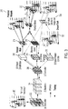
- FIG. 3 is conceptual layout diagram of a process for training the OHS head for a one-stage, anchor-free 3D object detection according to one embodiment.
- point cloud data 200 from the one or more sensors 102 is transformed/voxelized into a grid of cells (e.g. cuboid shaped voxels 202), and passed to a backbone network 204.
- a particular cell/voxel may contain zero or more points of the point cloud data.
- the step of voxelizing the point clouds may be by-passed, and raw point cloud data used for performing object detection without voxelizing the points.
- the backbone network 204 may be, for example, a 3D convolutional neural network, hosted by the inference module 110.
- One or more layers of the backbone network 204 may be invoked to extract various features of the point cloud data.
- One or more output feature maps with one or more neurons that may be mapped to the extracted features may be output by the backbone network 204.
- the output feature maps collapse to a bird's eye view (BEV).
- location of one or more voxels are projected to a corresponding location of a neuron of a particular output feature map.
- the one or more output feature maps are provided to a shared convolutional network 206 that provide one or more convolutional layers for hotspot classification, 3D box regression, and spatial relation encoding.
- the shared convolutional network 206 may include a hotspot classification subnet 208 for hotspot classification, box regression subnet 210 for 3D box regression, and spatial relation encoder subnet 212 for spatial relation encoding.
- the shared convolutional network 206, along with the various subnets 208-212, may be referred to as the OHS head.
- the OHS head may guide supervision and generate predicted 3D bounding boxes.
- the OHS head may be hosted by the inference module 110 and/or training module 118.
- the hotspot classification subnet 208 predicts the likelihood of object class categories for the neurons of the output feature map.
- the hotspot classification subnet 208 is a binary classifier that classifies a neuron of the output feature map as a hotspot or not, for a particular class of objects.
- the classification subnet 208 may take the form of a convolutional layer with K heatmaps, where a particular heatmap corresponds to a particular category/class of objects (e.g. cars, pedestrians, bicycles, traffic lights, etc.).
- the hotspots for a particular class of objects may be labeled as "1," whereas targets for the non-hotspots may be labeled as "0.”
- the hotspot classification subnet 208 applies a gradient mask 214 so that gradients for non-hotspots inside the ground truth bounding boxes are set to zero. This may allow non-hotspots to be ignored during training and may not contribute to backpropagation.
- the gradient mask 214 may output predicted hotspots 215 with a threshold level of confidence.
- a neuron on a feature map is identified as a hotspot if the hotspot prediction satisfies (e.g. is above or equal to) the threshold confidence.
- the hotspot classification subnet 208 performs a binary classification for hotspots and non-hotspots.
- the total classification loss may be averaged over the total number of hotspots and non-hotspots (excluding non-hotspots in ground truth bounding boxes).
- the box regression subnet 210 may be configured to engage in bounding box regression 216 for predicting 3D bounding boxes 218 based on the predicted hotspots 215. In one embodiment, the box regression subnet 210 regresses the location, dimension, and direction of the neurons of the output feature map corresponding to the predicted hotspots. The regressed data may be used to generate bounding boxes 220 to mark the detected objects in the 3D point cloud 200 space.
- bounding box regression is performed on only hotspots.
- an eight-dimensional vector [ d x , d y , z, log(l), log(w), log(h), cos(r), sin(r)] with parameters associated with location, dimension, and direction, is regressed to represent a detected object in the point cloud 200 space.
- Parameters d x , d y may be axis-aligned deviations of the hotspot on the feature map to the object centroid.
- log(/), log(w), log(h) are regressed instead of their original values because a log function scales down absolute values.
- cos(r), sin(r) may be regressed instead of the absolute value r, because they are constrained in the range of [-1, 1], instead of the range of [- ⁇ , ⁇ ] for the original angle value.
- soft argmin may be used to help regress location of the hotspot represented by d x , d y and z.
- the segment may be divided into N bins, each bin accounting for a length of b ⁇ a N .
- Soft argmin may address regression target imbalance by turning the regression into a classification problem that avoids regressing absolute values. In one embodiment the choices of a, b do not affect the performance of the approach as long as they cover the ranges of target values.
- the regression loss is computed for training the network to predict locations that are associated with hotspots.
- the spatial relation encoder subnet 212 is invoked during training for learning the relative spatial relationship of hotspots.
- Ground truth data 222 that is used for the training may implicitly provide relative spatial information between hotspots. Spatial relation encoding may thus reinforce the inherent spatial relations between hotspots.
- the axis-aligned deviations (dx, dy) from hotspots to object centroids predicted by the OHS head may vary with object orientations, and thus, may not show the inherent relation between hotspots and object centroids.
- the OHS head is trained to learn the inherent and invariant object-part relation via a supervision signal for coarse estimation of the hotspots.
- one or more target objects in the context of autonomous driving may be considered as rigid objects (e.g. cars), so the relative locations of hotspots to object centers may not change, and the relative locations may be determined with the help of bounding box centers and orientations.
- the relative hotspot location to the object center may be categorized into a vector representing partitions.
- the hotspot spatial relation encoder subnet 212 is trained with binary cross-entropy loss.
- Training of the OHS head may also include selection and assignment of hotspots 224.
- a point/voxel may be selected and assigned as a hotspot based on a determination as to its distance to the center of an object.
- the number of hotspots that are selected to represent an object may vary depending on the volume of the object.
- the total loss may be used for training the OHS head.
- the total loss may be backpropagated through the OHS head for modifying, for example, one or more weights associated with the neural networks representing the OHS head.
- the OHS head may be used for generating predicted 3D bounding boxes for predicted hotspots corresponding to certain classes of objects in the input point cloud. Based on the predictions, an autonomous vehicle such as the vehicle 100 of FIG. 1 , may be controlled.
- a K-dimensional vector of the K classification heatmaps corresponding to the object classes may be evaluated for identifying a largest confidence value of the vector.
- the identified value for a particular object class satisfies (e.g. is above or equal to) a threshold
- the corresponding location may be deemed to be a hotspot for the associated object instance.
- labels of objects associated with the identified hotspots may be obtained and output in association with the projected bounding boxes.
- an object instance may have multiple predicted hotspots that are above a given threshold.
- such a situation may be addressed via non-maximum suppression (NMS) with an Intersection Over Unit (IOU) threshold for picking a most confident hotspot for the object.
- NMS non-maximum suppression
- IOU Intersection Over Unit
- the IOU threshold may provide a threshold ratio of an overlapping area of ground truth hotspots to predicted hotspots. A most confident hotspot that satisfies the IOU threshold may be selected for a particular object.
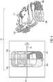
- FIG. 4 is a conceptual layout diagram of the spatial relation encoder subnet 212 dividing a bounding box 400 into four partitions (quadrants 402a-408a) according to one embodiment.
- the quadrants may be divided, in bird eye view, based on orientation 410 of the object (e.g. front-facing direction) and its perpendicular direction 412. In one embodiment, the quadrants are fixed with respect to the object's orientation 410.
- the quadrants may be identified, for example, via numbers (0, 1, 2, 3), colors (green, blue, purple, orange), or the like.
- points (e.g. hotspots) representing the objects are classified into their respective quadrants 402b-408b.
- FIGS. 5A-5C are conceptual layout diagrams of 3D object detection using hotspots according to one embodiment.
- Hotspots 500-516 are selected for objects that belong in one or more object categories (e.g. cars, pedestrians, bicycles, traffic lights, etc.).
- object categories e.g. cars, pedestrians, bicycles, traffic lights, etc.
- hotspots 500-514 are assigned for objects labeled as pedestrians
- a hotspot 516 is assigned to an object labeled as a bicycle.
- 3D bounding boxes labeled as a pedestrian 518-532, or bicycle 534 may be regressed for hotspots detected by the OHS head.
- 5C identifies example hotspots that may be fired/actuated for assigned hotspots 500, 502, and 516.
- the fired hotspots 500b, 502b, and 516b may be used for inferring 3D information for the associated object instance.
- FIG. 6 is a flow diagram of a process for training the OHS head according to one embodiment.
- the training module 118 may retrieve, from a data storage device, training data including ground truth data of one or more object instances in a point cloud.
- the ground truth data for a particular object instance may include, for example, bounding box information for the object instance.
- the bounding box information may include, without limitation, an object category to which the object instance belongs, and location, dimension, and direction of the bounding box.
- one or more of the points/voxels in a particular bounding box are assigned as hotspots.
- a collection of non-empty voxels within the bounding box are projected to a corresponding location of a neuron of a corresponding feature map, and the neuron is given a positive label of a hotspot.
- both empty and non-empty voxels of the bounding box are selected for being designated as hotspots.
- the hotspot classification subnet 208 may be invoked for classifying one or more neurons of the output feature map, as a hotspot.
- neurons predicted to be hotspots may be labeled as "1," while neurons that are not predicted to be hotspots may be labeled as "0.”
- a confidence value for the predictions are generated, and neurons that are predicted to be hotspots that satisfy a threshold confidence level are classified as hotspots.
- a classification loss may then be computed, where the total classification loss may be averaged over a total number of hotspots and non-hotspots (excluding non-hotspots in ground truth bounding boxes).
- the box regression subnet 210 may be invoked for regressing bounding boxes for the classified hotspots.
- an 8-dimensional vector [ d x , d y , z, log(l), log(w), log(h), cos(r), sin(r)] may be regressed to represent the object instance in the point cloud.
- soft argmin may be employed to regress the d x , d y , and z coordinates of the bounding box.
- a regression loss is computed for regressing the bounding box targets.
- the spatial relation encoder subnet 212 is invoked for learning the relative spatial relationship between hotspots.
- the spatial relation encoder subnet 212 may be configured to categorize the identified hotspots into a vector defined by a set number of parameters representing a set number of partitions.
- a partition loss may be computed for the hotspots based on the categorizing of the partitions.
- a total loss is computed as a weighted sum of the computed classification, regression, and partition losses.
- the total loss is backpropagated for adjusting one or more weights associated with the neural networks making up the OHS head.
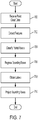
- FIG. 7 is a flow diagram of a process for a single pass, anchor-free detection of 3D objects according to one embodiment.
- point cloud data including points in 3D space is received from an input source, such as, for example, the one or more sensors 102 on top of an autonomous vehicle.
- the raw point cloud data, or the voxelized version of the data is provided to one or more neural networks, such as, for example, the backbone network 204, for extracting features from the point cloud data.
- One or more output feature maps may be generated based on the extracted features.
- An extracted feature map may include one or more neurons, where a particular neuron may be associated with one or more points or voxels.
- the shared convolutional network 206 and the hotspot classification subnet 208 are invoked for classifying the neurons as hotspots or not, for particular classes of objects.
- the hotspot classification subnet 208 may calculate a probability/confidence value that a neuron in the extracted feature map is a hotspot for the various classes of objects.
- a neuron with a confidence value higher than a threshold may be classified as a hotspot for a particular object instance associated with a particular class.
- a hotspot with the highest confidence value may be selected for representing the object.
- a bounding box is regressed for a particular hotspot.
- the regressing of the bounding box may be similar to the regressing of the bounding box in block 606 of FIG. 6 .
- labels and other types of annotation data for the object instance associated with the bounding box may be retrieved.
- labels/annotation data may include, for example, object classification ID, bounding box location coordinates and direction, and/or the like.
- the regressed bounding box is projected to the received point cloud space to mark the detected object.
- an autonomous vehicle such as the vehicle 100 of FIG. 1 , may be controlled based on the regressed bounding box information.
- processors may refer to one or more processors and/or one or more processing cores.
- the one or more processors may be hosted in a single device or distributed over multiple devices (e.g. over a cloud system).
- a processor may include, for example, application specific integrated circuits (ASICs), general purpose or special purpose central processing units (CPUs), digital signal processors (DSPs), graphics processing units (GPUs), and programmable logic devices such as field programmable gate arrays (FPGAs).
- ASICs application specific integrated circuits
- CPUs general purpose or special purpose central processing units
- DSPs digital signal processors
- GPUs graphics processing units
- FPGAs programmable logic devices
- each function is performed either by hardware configured, i.e., hard-wired, to perform that function, or by more general-purpose hardware, such as a CPU, configured to execute instructions stored in a non-transitory storage medium.
- a processor may be fabricated on a single printed circuit board (PCB) or distributed over several interconnected PCBs.
- a processor may contain other processing circuits; for example, a processing circuit may include two processing circuits, an FPGA and a CPU, interconnected on a PCB.
- first, second, third, etc. may be used herein to describe various elements, components, regions, layers and/or sections, these elements, components, regions, layers and/or sections should not be limited by these terms. These terms are only used to distinguish one element, component, region, layer or section from another element, component, region, layer or section. Thus, a first element, component, region, layer or section discussed herein could be termed a second element, component, region, layer or section, without departing from the spirit and scope of the inventive concept.
- any numerical range recited herein is intended to include all sub-ranges of the same numerical precision subsumed within the recited range.
- a range of "1.0 to 10.0" is intended to include all subranges between (and including) the recited minimum value of 1.0 and the recited maximum value of 10.0, that is, having a minimum value equal to or greater than 1.0 and a maximum value equal to or less than 10.0, such as, for example, 2.4 to 7.6.
- Any maximum numerical limitation recited herein is intended to include all lower numerical limitations subsumed therein and any minimum numerical limitation recited in this specification is intended to include all higher numerical limitations subsumed therein.
Landscapes
- Engineering & Computer Science (AREA)
- Physics & Mathematics (AREA)
- Theoretical Computer Science (AREA)
- General Physics & Mathematics (AREA)
- Evolutionary Computation (AREA)
- Artificial Intelligence (AREA)
- Health & Medical Sciences (AREA)
- Software Systems (AREA)
- Computing Systems (AREA)
- Data Mining & Analysis (AREA)
- General Health & Medical Sciences (AREA)
- Multimedia (AREA)
- General Engineering & Computer Science (AREA)
- Life Sciences & Earth Sciences (AREA)
- Mathematical Physics (AREA)
- Biomedical Technology (AREA)
- Biophysics (AREA)
- Computational Linguistics (AREA)
- Molecular Biology (AREA)
- Computer Vision & Pattern Recognition (AREA)
- Radar, Positioning & Navigation (AREA)
- Remote Sensing (AREA)
- Computer Graphics (AREA)
- Medical Informatics (AREA)
- Computer Networks & Wireless Communication (AREA)
- Electromagnetism (AREA)
- Databases & Information Systems (AREA)
- Automation & Control Theory (AREA)
- Business, Economics & Management (AREA)
- Game Theory and Decision Science (AREA)
- Aviation & Aerospace Engineering (AREA)
- Geometry (AREA)
- Evolutionary Biology (AREA)
- Bioinformatics & Computational Biology (AREA)
- Bioinformatics & Cheminformatics (AREA)
- Probability & Statistics with Applications (AREA)
- Traffic Control Systems (AREA)
- Image Analysis (AREA)
- Transportation (AREA)
- Mechanical Engineering (AREA)
Applications Claiming Priority (3)
| Application Number | Priority Date | Filing Date | Title |
|---|---|---|---|
| US201962939548P | 2019-11-22 | 2019-11-22 | |
| US202063050654P | 2020-07-10 | 2020-07-10 | |
| US16/985,092 US11543534B2 (en) | 2019-11-22 | 2020-08-04 | System and method for three-dimensional object detection |
Publications (1)
| Publication Number | Publication Date |
|---|---|
| EP3825908A1 true EP3825908A1 (fr) | 2021-05-26 |
Family
ID=73452057
Family Applications (1)
| Application Number | Title | Priority Date | Filing Date |
|---|---|---|---|
| EP20207776.4A Withdrawn EP3825908A1 (fr) | 2019-11-22 | 2020-11-16 | Système et procédé de détection d'objet tridimensionnel |
Country Status (5)
| Country | Link |
|---|---|
| US (1) | US11543534B2 (fr) |
| EP (1) | EP3825908A1 (fr) |
| JP (1) | JP2021082296A (fr) |
| KR (1) | KR20210064067A (fr) |
| CN (1) | CN112836564A (fr) |
Families Citing this family (22)
| Publication number | Priority date | Publication date | Assignee | Title |
|---|---|---|---|---|
| US11543534B2 (en) * | 2019-11-22 | 2023-01-03 | Samsung Electronics Co., Ltd. | System and method for three-dimensional object detection |
| US11731662B2 (en) * | 2020-10-08 | 2023-08-22 | Ford Global Technologies, Llc | Autonomous vehicle system for detecting pedestrian presence |
| US11361201B2 (en) | 2020-10-08 | 2022-06-14 | Argo AI, LLC | Systems and methods for determining an object type and an attribute for an observation based on fused sensor data |
| WO2023107599A1 (fr) * | 2021-12-08 | 2023-06-15 | Carnegie Mellon University | Système et procédé d'attribution de polygones concaves complexes en tant que boîtes de délimitation |
| US12536780B2 (en) | 2021-03-30 | 2026-01-27 | Carnegie Mellon University | System and method for detecting, reading and matching in a retail scene |
| CN113256622A (zh) * | 2021-06-28 | 2021-08-13 | 北京小白世纪网络科技有限公司 | 基于三维图像的目标检测方法、装置及电子设备 |
| US20250088665A1 (en) * | 2021-07-20 | 2025-03-13 | Lg Electronics Inc. | Point cloud data transmission device, point cloud data transmission method, point cloud data reception device, and point cloud data reception method |
| US12051324B2 (en) * | 2021-07-28 | 2024-07-30 | GM Global Technology Operations LLC | Collaborative illumination |
| KR102681992B1 (ko) | 2021-08-17 | 2024-07-04 | 충북대학교 산학협력단 | 자율 주행을 위한 단일 계층 3차원 다중 객체 검출 장치 및 방법 |
| CN113591811A (zh) * | 2021-09-28 | 2021-11-02 | 湖南大学 | 零售货柜商品搜索识别方法、系统及计算机可读存储介质 |
| KR102660084B1 (ko) | 2021-09-30 | 2024-04-22 | 연세대학교 산학협력단 | 3d 객체 탐지 장치 및 방법 |
| KR102394024B1 (ko) * | 2021-11-19 | 2022-05-06 | 서울대학교산학협력단 | 자율 주행 차량에서 객체 검출을 위한 준지도 학습 방법 및 이러한 방법을 수행하는 장치 |
| KR102416691B1 (ko) * | 2021-11-24 | 2022-07-06 | 주식회사 마크애니 | 다중 객체 인식용 기계학습을 위한 다중 데이터셋 기반 학습 장치 및 방법 |
| US12046049B2 (en) * | 2021-12-01 | 2024-07-23 | Motional Ad Llc | Automatically detecting traffic signals using sensor data |
| CN113989519B (zh) * | 2021-12-28 | 2022-03-22 | 中科视语(北京)科技有限公司 | 一种长尾目标检测方法及系统 |
| JP7418481B2 (ja) | 2022-02-08 | 2024-01-19 | 本田技研工業株式会社 | 学習方法、学習装置、移動体制御装置、移動体制御方法、およびプログラム |
| JP7450654B2 (ja) * | 2022-02-10 | 2024-03-15 | 本田技研工業株式会社 | 移動体制御装置、移動体制御方法、学習装置、学習方法、およびプログラム |
| CN115661517A (zh) * | 2022-10-18 | 2023-01-31 | 佛山市南海区广工大数控装备协同创新研究院 | 一种基于单阶段的深度学习神经网络目标检测方法 |
| US12579821B2 (en) * | 2023-02-16 | 2026-03-17 | Nvidia Corporation | Object detection for autonomous systems and applications |
| CN117218625A (zh) * | 2023-08-16 | 2023-12-12 | 上海应用技术大学 | 一种基于融合采样策略和图网络的3d目标检测方法 |
| US20250115250A1 (en) * | 2023-10-05 | 2025-04-10 | Nec Laboratories America, Inc. | Instantaneous perception of fine-grained 3d motion |
| KR102767260B1 (ko) * | 2024-07-12 | 2025-02-26 | 대한민국(방위사업청장) | 포인트 클라우드 특성을 고려한 3차원 객체 탐지 장치 및 방법 |
Citations (3)
| Publication number | Priority date | Publication date | Assignee | Title |
|---|---|---|---|---|
| WO2018170472A1 (fr) * | 2017-03-17 | 2018-09-20 | Honda Motor Co., Ltd. | Détection conjointe d'objets 3d et estimation d'orientation par fusion multimodale |
| US20180348346A1 (en) * | 2017-05-31 | 2018-12-06 | Uber Technologies, Inc. | Hybrid-View Lidar-Based Object Detection |
| US20190147245A1 (en) * | 2017-11-14 | 2019-05-16 | Nuro, Inc. | Three-dimensional object detection for autonomous robotic systems using image proposals |
Family Cites Families (16)
| Publication number | Priority date | Publication date | Assignee | Title |
|---|---|---|---|---|
| US10460180B2 (en) * | 2017-04-20 | 2019-10-29 | GM Global Technology Operations LLC | Systems and methods for visual classification with region proposals |
| US10595175B2 (en) * | 2017-06-23 | 2020-03-17 | Veniam, Inc. | Methods and systems for detecting anomalies and forecasting optimizations to improve smart city or region infrastructure management using networks of autonomous vehicles |
| US11334762B1 (en) * | 2017-09-07 | 2022-05-17 | Aurora Operations, Inc. | Method for image analysis |
| EP3477616A1 (fr) * | 2017-10-27 | 2019-05-01 | Sigra Technologies GmbH | Procédé pour commander un véhicule à l'aide d'un système d'apprentissage machine |
| US10674332B2 (en) * | 2017-12-01 | 2020-06-02 | Veniam, Inc. | Systems and methods for the data-driven and distributed interoperability between nodes to increase context and location awareness in a network of moving things, for example in a network of autonomous vehicles |
| EP3709216B1 (fr) * | 2018-02-09 | 2023-08-02 | Bayerische Motoren Werke Aktiengesellschaft | Procédés et appareils de détection d'objets dans une scène représentée par des données de profondeur d'un capteur de détection de plage et des données d'image d'une caméra |
| US10999731B2 (en) * | 2018-02-20 | 2021-05-04 | Veniam, Inc. | Systems and methods for real-time handling and processing of data in a network of moving things |
| WO2019178548A1 (fr) * | 2018-03-15 | 2019-09-19 | Nvidia Corporation | Détermination d'emplacements de stationnement manoeuvrables pour véhicules autonomes |
| US20190310651A1 (en) * | 2018-04-10 | 2019-10-10 | Uber Technologies, Inc. | Object Detection and Determination of Motion Information Using Curve-Fitting in Autonomous Vehicle Applications |
| US10915793B2 (en) * | 2018-11-08 | 2021-02-09 | Huawei Technologies Co., Ltd. | Method and system for converting point cloud data for use with 2D convolutional neural networks |
| US11755018B2 (en) * | 2018-11-16 | 2023-09-12 | Uatc, Llc | End-to-end interpretable motion planner for autonomous vehicles |
| US10891518B1 (en) * | 2018-12-14 | 2021-01-12 | Waymo Llc | Auto labeler |
| US20210142160A1 (en) * | 2019-11-08 | 2021-05-13 | Nvidia Corporation | Processor and system to identify out-of-distribution input data in neural networks |
| US11543534B2 (en) * | 2019-11-22 | 2023-01-03 | Samsung Electronics Co., Ltd. | System and method for three-dimensional object detection |
| US12127085B2 (en) * | 2020-07-29 | 2024-10-22 | Aurora Operations, Inc. | Systems and methods for mitigating vehicle pose error across an aggregated feature map |
| US11282291B1 (en) * | 2021-02-09 | 2022-03-22 | URC Ventures, Inc. | Determining object structure using fixed-location cameras with only partial view of object |
-
2020
- 2020-08-04 US US16/985,092 patent/US11543534B2/en active Active
- 2020-11-16 EP EP20207776.4A patent/EP3825908A1/fr not_active Withdrawn
- 2020-11-17 KR KR1020200153966A patent/KR20210064067A/ko not_active Withdrawn
- 2020-11-18 CN CN202011293713.3A patent/CN112836564A/zh active Pending
- 2020-11-20 JP JP2020193640A patent/JP2021082296A/ja active Pending
Patent Citations (3)
| Publication number | Priority date | Publication date | Assignee | Title |
|---|---|---|---|---|
| WO2018170472A1 (fr) * | 2017-03-17 | 2018-09-20 | Honda Motor Co., Ltd. | Détection conjointe d'objets 3d et estimation d'orientation par fusion multimodale |
| US20180348346A1 (en) * | 2017-05-31 | 2018-12-06 | Uber Technologies, Inc. | Hybrid-View Lidar-Based Object Detection |
| US20190147245A1 (en) * | 2017-11-14 | 2019-05-16 | Nuro, Inc. | Three-dimensional object detection for autonomous robotic systems using image proposals |
Also Published As
| Publication number | Publication date |
|---|---|
| KR20210064067A (ko) | 2021-06-02 |
| JP2021082296A (ja) | 2021-05-27 |
| CN112836564A (zh) | 2021-05-25 |
| US11543534B2 (en) | 2023-01-03 |
| US20210157006A1 (en) | 2021-05-27 |
Similar Documents
| Publication | Publication Date | Title |
|---|---|---|
| US11543534B2 (en) | System and method for three-dimensional object detection | |
| US11703566B2 (en) | Multi-modal sensor data association architecture | |
| US11977382B2 (en) | Ranking agents near autonomous vehicles by mutual importance | |
| US11379998B2 (en) | Detector-tracker architecture | |
| US10963709B2 (en) | Hierarchical machine-learning network architecture | |
| US11488392B2 (en) | Vehicle system and method for detecting objects and object distance | |
| KR20210074193A (ko) | 궤적 예측을 위한 시스템 및 방법 | |
| JP2022554184A (ja) | オブジェクトの検出及び追跡 | |
| JP2022552138A (ja) | 衝突回避知覚システム | |
| KR102695522B1 (ko) | 이미지 인식 모델을 트레이닝시키는 장치 및 방법과 이미지 인식 장치 및 방법 | |
| IL271568B2 (en) | Rare instance classifiers | |
| Dimitrievski et al. | Weakly supervised deep learning method for vulnerable road user detection in FMCW radar | |
| US12555388B2 (en) | Determination of object trajectory from augmented image data | |
| WO2023009180A1 (fr) | Suivi d'objet par lidar | |
| US20250078519A1 (en) | Road geometry estimation for vehicles | |
| Juyal et al. | Object Classification Using A rtificial I ntelligence Technique sin Autonomous Vehicles | |
| Zhao et al. | Vision-based perception with safety awareness for uas autonomous landing | |
| Aishwarya et al. | Robust deep learning based speed bump detection for autonomous vehicles in Indian scenarios | |
| US12411247B2 (en) | Lidar sensor denoising for adverse conditions and/or nonsalient objects | |
| KR20240080189A (ko) | 거리 측정 방법 및 이를 이용하는 거리 측정 장치 | |
| US12416720B2 (en) | Scintillation-based neural network for radar target classification | |
| US12576859B1 (en) | Object classification with out-of-distribution detection | |
| KR102670260B1 (ko) | 거리 측정 방법 및 이를 이용하는 거리 측정 장치 | |
| US20240232647A9 (en) | Efficient search for data augmentation policies | |
| Miekkala | 3D object detection using lidar point clouds and 2D image object detection |
Legal Events
| Date | Code | Title | Description |
|---|---|---|---|
| PUAI | Public reference made under article 153(3) epc to a published international application that has entered the european phase |
Free format text: ORIGINAL CODE: 0009012 |
|
| STAA | Information on the status of an ep patent application or granted ep patent |
Free format text: STATUS: THE APPLICATION HAS BEEN PUBLISHED |
|
| AK | Designated contracting states |
Kind code of ref document: A1 Designated state(s): AL AT BE BG CH CY CZ DE DK EE ES FI FR GB GR HR HU IE IS IT LI LT LU LV MC MK MT NL NO PL PT RO RS SE SI SK SM TR |
|
| STAA | Information on the status of an ep patent application or granted ep patent |
Free format text: STATUS: REQUEST FOR EXAMINATION WAS MADE |
|
| 17P | Request for examination filed |
Effective date: 20210622 |
|
| RBV | Designated contracting states (corrected) |
Designated state(s): AL AT BE BG CH CY CZ DE DK EE ES FI FR GB GR HR HU IE IS IT LI LT LU LV MC MK MT NL NO PL PT RO RS SE SI SK SM TR |
|
| STAA | Information on the status of an ep patent application or granted ep patent |
Free format text: STATUS: EXAMINATION IS IN PROGRESS |
|
| 17Q | First examination report despatched |
Effective date: 20220419 |
|
| STAA | Information on the status of an ep patent application or granted ep patent |
Free format text: STATUS: THE APPLICATION IS DEEMED TO BE WITHDRAWN |
|
| 18D | Application deemed to be withdrawn |
Effective date: 20220830 |