EP3825982A1 - Erkennung einer kollisionsgefahr zwischen einem boot und einem leuchtenden objekt - Google Patents
Erkennung einer kollisionsgefahr zwischen einem boot und einem leuchtenden objekt Download PDFInfo
- Publication number
- EP3825982A1 EP3825982A1 EP19211016.1A EP19211016A EP3825982A1 EP 3825982 A1 EP3825982 A1 EP 3825982A1 EP 19211016 A EP19211016 A EP 19211016A EP 3825982 A1 EP3825982 A1 EP 3825982A1
- Authority
- EP
- European Patent Office
- Prior art keywords
- boat
- images
- camera
- sequence
- light source
- Prior art date
- Legal status (The legal status is an assumption and is not a legal conclusion. Google has not performed a legal analysis and makes no representation as to the accuracy of the status listed.)
- Withdrawn
Links
Images




Classifications
-
- G—PHYSICS
- G08—SIGNALLING
- G08G—TRAFFIC CONTROL SYSTEMS
- G08G3/00—Traffic control systems for marine craft
- G08G3/02—Anti-collision systems
-
- G—PHYSICS
- G06—COMPUTING OR CALCULATING; COUNTING
- G06T—IMAGE DATA PROCESSING OR GENERATION, IN GENERAL
- G06T7/00—Image analysis
- G06T7/20—Analysis of motion
- G06T7/246—Analysis of motion using feature-based methods, e.g. the tracking of corners or segments
-
- G—PHYSICS
- G06—COMPUTING OR CALCULATING; COUNTING
- G06T—IMAGE DATA PROCESSING OR GENERATION, IN GENERAL
- G06T7/00—Image analysis
- G06T7/80—Analysis of captured images to determine intrinsic or extrinsic camera parameters, i.e. camera calibration
-
- G—PHYSICS
- G06—COMPUTING OR CALCULATING; COUNTING
- G06V—IMAGE OR VIDEO RECOGNITION OR UNDERSTANDING
- G06V20/00—Scenes; Scene-specific elements
- G06V20/10—Terrestrial scenes
-
- H—ELECTRICITY
- H04—ELECTRIC COMMUNICATION TECHNIQUE
- H04N—PICTORIAL COMMUNICATION, e.g. TELEVISION
- H04N23/00—Cameras or camera modules comprising electronic image sensors; Control thereof
- H04N23/80—Camera processing pipelines; Components thereof
- H04N23/84—Camera processing pipelines; Components thereof for processing colour signals
Definitions
- the invention relates to boat safety and more particularly to a method and device for avoiding collision between a boat and a luminous object in a water area such as e.g. an ocean, a sea or a lake.
- the present invention aims in particular at providing a solution of boat-embedded system which allows avoiding the collision of a boat with a luminous object located in a water area.
- RADAR device which sends waves that can reflect on the objects.
- the RADAR device can detect the direction and the distance of the object.
- Such type of RADAR device works on day time as well as on night time, but cannot identify the objects otherwise than using their shape.
- the camera is of the RGB (Red Green Blue) type, known in the art, and allows manually detecting objects.
- the RGB camera generates images which are displayed on a screen and an operator analyses the images displayed on the screen to detect any object that could be dangerous for the boat.
- such system may only be used during day time as images are mainly dark during night time.
- the camera is of the thermal type and allows also manually detecting objects on a screen, but in this case, images show a thermal representation of the environment, allowing therefore detecting objects also at night time.
- thermal cameras are expensive.
- the existing systems only allow identifying objects using their shape and distance, which may prove to be inaccurate and dangerous in some situations.
- an operator e.g. the skipper of the boat, monitors the images on a screen to detect the objects, which is time-consuming for said operator and prevents him of performing other tasks, which could even be dangerous if the operator is alone on the boat.
- the invention provides a method of detecting a risk of collision between a boat and a luminous object in a water area using a camera module mounted on said boat, said camera module comprising a RGB camera, said boat being characterized by its course, said method comprising the steps of:
- the method according to the invention allows to automatically estimate the course direction of an illuminated object at night in a water area (e.g. an open sea area) and detecting a risk of collision between the boat and said luminous object.
- a water area e.g. an open sea area
- RGB Red Green Blue
- the method comprises, consequently to the risk detection, a step of triggering an alarm.
- the alarm may be a sound, a display or a command.
- the method comprises a step of avoiding the object based on the estimated course direction of said object.
- This collision avoidance may be realized manually (e.g. by the skipper of the boat) consequently to the alarm triggering or automatically (e.g. by the autopilot module of the boat when the boat is provided with such an autopilot module) consequently to the risk detection or to the alarm triggering.
- the alarm is a sound alarm or a display alarm (e.g. on a control screen of the boat)
- the skipper may manoeuvre the boat to avoid the object.
- the alarm is a command alarm
- the alarm command may be sent directly to the autopilot of the boat to manoeuvre the boat and avoid the object.
- the risk detection may trigger automatically the collision avoidance through the autopilot module.
- the series of polar angles is calculated using a rotation matrix from an image plan of the images to a boat reference frame coordinate system of the boat for each image of the sequence of images.
- the use of a rotation matrix is a simple manner to calculate the series of polar angles.
- the method comprises, before the step of calculating a series of polar angles, a step of estimating the distance between the boat and the at least one light source using the images of the at least one sequence of images.
- This estimation of the distance may be realized using the distance in pixels between the boat and the object on the images and/or using translation and rotation matrixes between the image plan of the images, the camera and the boat. The distance gives an extra information to improve collision avoidance.
- the estimation of the distance between the boat and the at least one light source comprises:
- the estimation of the course direction of the object with regard to the boat comprises estimating the angular speed of the object using said series of calculated polar angles.
- the angular speed gives a basic, but extra information to improve collision avoidance.
- the method comprises a step of estimating the linear speed of the object using the estimated distance and said series of calculated polar angles.
- the linear speed gives an extra relevant information to improve collision avoidance.
- the estimation of the linear speed of the object comprises deriving the estimated position of the object with respect to time to obtain a resulting vector, and then calculating the magnitude of said resulting vector.
- the method comprising a step of determining the colour of the at least one detected light source.
- the colour of the lights may give an indication of the type of luminous object, in particular according to the International Association of Marine Aids to Navigation and Lighthouse authorities (IALA).
- IALA International Association of Marine Aids to Navigation and Lighthouse authorities
- the method comprises a step of identifying the object in order to improve the collision avoidance.
- the identification of the object may be realized using the estimated course direction of the object and/or the linear speed of the object and/or the angular speed of the object and/or the number of light(s) of the object and/or the configuration of the lights on the object and/or the determined colour of the light(s) of the object.
- the method comprises, before the step of detection of at least one light source, a step of detecting a night condition using the colour distribution in the images of said sequence of images.
- the detection of the at least one light source comprises determining the colour if the pixels of the image and detecting a light source when the level of colour of a group of pixels is greater than a brightness threshold.
- the invention also relates to a system for detecting a risk of collision between a boat and a luminous object in a water area, said system being intended to be mounted on-board said boat and comprising a camera module and a processing module connected to said camera module via a communication link, said camera module comprising a RGB camera configured to generate at least one sequence of images using said camera and send said generated at least one sequence of images to the processing module, said boat being characterized by its course, said processing module being configured to:
- the processing module is configured to trigger an alarm.
- the object may be avoided manually by the skipper of the boat consequently to said alarm trigger.
- the processing module is configured to automatically avoid the object based on the estimated course direction of said object.
- the processing module may be configured to control the boat, directly or via an automatic pilot module, in order to avoid the object using the estimated course direction of the object.
- the processing module is configured to calculate the polar angles using a rotation matrix from the image plan to a boat reference frame coordinate system for each image of the sequence of images.
- the processing module is configured to estimate the distance between the boat and the at least one light source using the images of the sequence of images. This estimation may be realized using the distance in pixels between the boat and the object on the images and/or translation and rotation matrixes between the image plan of the images, the camera and the boat.
- the processing module is configured to:
- the processing module is configured to estimate the angular speed of the object using said series of calculated polar angles.
- the processing module is configured to estimate the linear speed of the object using said estimated distance and said series of calculated polar angles.
- the processing module is configured to derive the estimated position with respect to time, and then calculate the magnitude of the resulting vector.
- the processing module is configured to determine the colour of the at least one detected light source.
- the processing module is configured to identify the object.
- the processing module is configured to identify the object using the estimated course direction of the object and/or the angular speed of the object and/or the linear speed of the object and/or the number of light(s) of the object and/or the configuration of the lights on the object and/or the determined colour of the light(s) of the object.
- the processing module is configured to detect a night condition using the colour distribution in the images of said sequence of images.
- the processing module is configured to determine the colour if the pixels of the image and detect a light source when the level of colour of a group of pixels is above a brightness threshold.
- the invention also relates to a boat comprising a system as described previously.
- the boat may be e.g. a sailing boat, a racing boat, a ship or any kind of vessel.
- the boat comprise a hull and a mast, wherein the camera module is mounted on said mast.
- the collision avoiding system allows to detect and avoid an object in a water area during night time using a camera module mounted on a boat.
- the water area may be an ocean, a sea, a lake or any water area suitable for a boat.
- the boat may be a sailing boat or a motorboat.
- the boat is a racing boat or a cruising boat.
- FIG 1 illustrates a boat 1 according to the invention navigating in a water area 2 in a direction D toward another vessel 5.
- the boat 1 is a sailing boat and comprises a hull 10, a mast 20 and a collision avoidance system 30 according to the invention.
- a boat 1 reference frame coordinate system (x b , y b , z b ), called “Boat CS”
- Boat CS is associated to the boat 1.
- a mast 20 reference frame coordinate system (x f , y f , z f ), called "Fixture CS” is associated to the mast 20.
- the boat 1 is characterized by its course, which may be static (i.e. fixed) or dynamic (movement).
- the system 30 comprises a camera module 310, a processing module 320 and a navigation module 330.
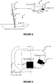
- the camera module 310 comprises a housing 311, an arm 312, a cover plate 313, a RGB camera 314 and a sensor 315 (shown on figures 4 and 5 ).
- a camera module 310 reference frame coordinate system (x m , y m , z m ), called “Module CS”
- Mode CS is associated to the camera module 310.
- a camera 314 reference frame coordinate system (x c , y c , z c ), called “Camera CS”
- the camera 314 is associated with an image plane (called "Image Plane") in which the images are generated.
- the Image Plane is perpendicular to the optical axis OA of the camera 314 and defines an image reference frame coordinate system ( u , v ) in pixels.
- the camera 314 and the sensor 315 are mounted in the housing 311.
- the camera 314 is of the RGB (Red Green Blue) type, known in the art. As shown on figure 2 , the camera 314 is oriented toward the front of the boat 1 to generate images showing the front environment of the boat on an angular width ⁇ .
- the sensor 315 is for example of the MEMS type and allows to measure acceleration and gyroscopic data along the three-dimensional axes of the camera 314 reference frame coordinate system.
- the housing 311 is mounted on the mast 20 via the arm 312.
- the cover plate 313 allows to protect the camera 314 from the sun rays.
- the camera module 310 comprises a single camera 314 for the sake of clarity.
- the camera module 310 might comprise a plurality of cameras, for example one RGB camera 314 and other cameras (RGB, thermal, etc.).
- the camera 314 is configured to generate a sequence of coloured images and send said sequence of images to the processing module 320, for example at a frame rate of 3 to 4 images per second.
- the images are set in the Image Plane, as illustrated on figure 6 .
- the camera module 310 is advantageously mounted at the top of the mast 20 in order to allow the camera 314 to generate sequence of images showing a wide shot of the environment (water area 2) and improve therefore the accuracy of the identification of objects like the vessel 5.
- a sequence of image may comprise one or several images, for example 25, 30, 50, 60, 100 or more images.
- Navigation lights help boaters determine the give-way vessel when encountering each other at night. These lights must be displayed from sunset to sunrise and during periods of restricted visibility, such as fog.
- Sidelights also called combination lights
- the red light indicates a vessel's port (left) side; the green indicates a vessel's starboard (right) side.
- the sternlight is a white light, which is seen only from behind or nearly behind the vessel.
- the masthead light is a white light, which shines forward and to both sides and is required on all power-driven vessels.
- the masthead light and sternlight may be combined into an all-round white light; power-driven vessels 12 meters / 39.4 feet in length or longer must have a separate masthead light.
- a masthead light must be displayed by all vessels when under engine power. The absence of this light indicates a sailing vessel because sailboats under sail display only sidelights and a sternlight.
- the all-round white light concerns on power-driven vessels less than 12 meters / 39.4 feet in length, this light may be used to combine a masthead light and sternlight into a single white light that can be seen by other vessels from any direction. This light serves as an anchor light when sidelights are extinguished.
- the vessel 5 comprises a white masthead light 51, a red left sidelight 52 and a green right sidelight 53.
- the processing module 320 is configured to receive sequences of images generated by the camera 314 and, for a given received sequence of images:
- processing module 320 is further configured to:
- the processing module 320 is configured for processing the received images at the same frequency that the frame rate of the camera 314, for example 3 to 4 images per second.
- the processing module 320 may process each image of the sequence when it is received or store a batch of images and process the whole sequence of images at once.
- the processing module 320 is configured to detect a night-time condition using a received sequence of images. More precisely, the processing module 320 is configured to determine the colour distribution in the sequence of images. To this end, the processing module 320 is configured to determine the level of darkness of each pixel of the images.
- An image generated by a camera 314 consists in one image coded using levels of red, one image coded using levels of green and one image coded using levels of blue. For example, levels of red, green and blue may each vary from 0 to 255. The level (0, 0, 0) correspond to the black colour whereas the level (255, 255, 255) corresponds to the white colour.
- the level of darkness, also called luminance may be computed by calculating the mean of the three level values. It is a weighted mean with more weight attributed to the green colour and less to blue.
- a predetermined darkness threshold for example 50 or 100
- the processing module 20 determines that the boat 1 navigates at night time.
- the navigation module 330 allows the skipper to navigate the boat 1.
- the navigation module 330 collects data from sensors or modules of the boat 1, such as e.g. the location, the heading or the speed of the boat 1.
- the camera module 310, the processing module 320 and the navigation module 330 are linked by a communication bus (not represented) which allows the camera module 310 to send images and sensor 315 data to the processing module 320 and the navigation module 330 to send navigation data, such as e.g. the localisation, the heading and the speed of the boat 1, to the processing module 320.
- a communication bus not represented
- the boat 1 navigates in an open sea and the vessel 5 is in the field of the camera 314 of the camera module 310.
- the camera 314 generates a sequence of images in a step S1. These images are sent by the camera 314 to the processing module 320.
- the processing module 320 may first detect if the boat 1 navigates in day or night conditions using a first received set of images. If the processing module 320 detects a night condition, it performs automatically the following step S2 to S7 on each image (i.e. each iteration of the method), otherwise, no further action is realized.
- Ship lights or lighthouse lights appear on the images of a sequence as an illuminated pixel or group of illuminated pixels.
- the color of each light source area corresponding to a ship light 51, 52, 53 may be red, green or white.
- the light of a lighthouse may be red, green, white or yellow and may be blinking. In the latter case, if the light source does not appear in all the images of the sequence of images, the processing module 20 may determine that the light source is blinking.
- the detection of a light source 51, 52, 53 corresponds to the detection of an object that should thus be avoided, for example the vessel 5 in this example.
- the representation of a light source 51, 52, 53 on an image has a drastically different colour distribution from the rest of the image, in particular in an open sea environment.
- Detection of light sources 51, 52, 53 in a sequence of images may be done using conventional image thresholding methods as described here above.
- the colour of each light source area may be determined mainly red, green or white as previously detailed.
- the processing module 320 determines that said group of pixels corresponds to a light source 51, 52, 53.
- the detection might also be done using more complex methods, for example a Convolutional Neural Network (CNN) that contains image enhancement layers, or any other unsupervised adapted method.
- CNN Convolutional Neural Network
- the processing module 320 calculates a transformation matrix T which allows switching from the camera 314 reference frame coordinates system (Camera CS) to the boat 1 reference frame coordinates system (Boat CS).
- the transformation matrix T can be directly calculated using the mounting parameters of the camera module 310 on the mast 20, comprising the mast 20 length, the rake angle (inclination of the camera 314) and the distance from the mast 20 to the front of the boat 1.
- the transformation matrix T is a composite matrix of the rotation matrix resulting from the camera module 310 angles (raw, pitch, yaw), the rotation and translation from the camera 314 reference frame coordinate system (Camera CS) to the mast 20 reference frame coordinate system (Fixture CS) using the fall-back angle, the mast 20 rake and the mast 20 height, and finally a translation to the front of the boat 1.
- the kinematics model of the system 30, initialized using the mounting parameters is updated with the information collected by the boat 1 bus data, especially the speed of the boat 1, provided by the navigation module 330 and the data from the sensor 315 of the camera module 310.
- the kinematics model is the study of the movement of the camera module 310 in relation to the movement of the boat 1 itself, in order to define a transformation matrix T to map anything that is seen in the image into the boat 1 reference frame coordinate system (Boat CS).
- the model has fix parameters (mast 20 height, mast 20 rake, mounting angle of the camera module 310, camera 314 fall-back angle, etc.), while other parameters may be ignored (e.g.
- variable parameters that change over time (movements of the boat's 1 and gyroscopic data).
- the variable parameters can be synchronized on each iteration with the image data, enabling for the update of the transformation matrix T.
- the vessel 5 appears on the image at a position P, called “real position P” in pixel coordinates on the image in the camera 314 reference frame coordinate system (Camera CS), and is considered to be located at a distance R, called “real distance”, from the boat 1 in the boat 1 reference frame coordinate system (Boat CS).
- the white masthead light source 51 is mounted at a height h and appears on the image at a position P light , called “light position P light ", in pixel coordinates in the camera 314 reference frame coordinate system (Camera CS) and can be perceived after a projection from the camera 314 reference frame coordinate system to the boat 1 reference frame coordinate system (Boat CS) as located at a distance R light to the light, called “light distance” R light ".
- Roat CS boat 1 reference frame coordinate system
- Camera CS camera 314 reference frame coordinates system
- the distance ⁇ P light - P ⁇ represents the error in number of pixels, between the light position and the real object position as a function of the distance R, depending on the height h.
- the bias factor ⁇ satisfies advantageously the following condition: the brightest and the biggest the light is, the more likely it is to be closer than estimated, especially when the position is closer to the horizon height.
- the distance estimation algorithm at night first creates a transformation matrix T from the camera 314 reference frame CS to the boat's 1 reference frame coordinate system (Boat CS), then calculates the light distance R light using the light position P light and said transformation matrix T. Using the equations [1] and [2], a new estimation of the real position "P" of the vessel 5 is made, which is then projected in the boat 1 reference frame coordinate system (Boat CS) to calculate an estimation of the real distance R of the vessel 5 with regard to the boat 1.
- the transformation matrix T which is the mapping function from the image to the boat 1 reference frame coordinate system, is used to calculate the polar angle, called "Phi light ", from the boat 1 to the light source 51 for each image of the sequence of images.
- the transformation matrix T which is the mapping function from the image to the boat 1 reference frame coordinate system, is used to calculate the polar angle, called "Phi light ", from the boat 1 to the light source 51 for each image of the sequence of images.
- the comparison of the polar angle Phi to the light source in a sequence of real-time images allows to derive a series of polar angles which enables to estimate the angular speed (or velocity) and the course direction (left, right or static) of the light sources 51, 52, 53 and therefore of the vessel 5.
- the angular speed of the vessel 5 is calculated with reference to the boat 1 reference frame coordinate system (Boat CS), and indicates at what speed the vessel 5 is heading towards or away from the course of the boat 1.
- ⁇ L(t) (Phi(t),R(t)) ⁇ to each a polar angle "Phi(t)” is calculated and a distance "R(t)” is estimated as previously described.
- d(Phi) (Phi(t) - Phi(t - dt)) / dt, where dt is the time step between the current frame F and the previous one, can be calculated.
- the sign of d(Phi) indicates whether the light source is heading towards or away from the course of the boat 1 (i.e. the x b axis of Boat CS on Figure 4 ).
- the derivate of the real distance R with regard to time d(R) can be calculated. Its sign indicates whether the vessel 5 is heading towards the boat 1 or moving away, in order to add an additional, but less reliable, security layer, given the assumptions that at least one light source is mounted on the top of the vessel 5.
- the linear speed V of the vessel 5 is the magnitude of the velocity vector, which is the derivative of the estimated position P with regard to time t.
- the vessel 5 may be identified using its estimated course direction and/or its speed and/or the number of light(s) 51, 52, 53 and/or the configuration/positions of the lights 51, 52, 53 of the vessel 5 and/or the determined colour of the light(s) 51, 52, 53 of the vessel 5.
- the information about the different light sources 51, 52, 53 may be kept in a buffer of a memory zone of the processing module 320.
- the different features of the vessel 5 colour of light sources 51, 52, 53, course direction, speed
- Said table may store in particular the features of each type of vessel 5 according to the navigational light rules of IALA (International Association of Marine Aids to Navigation and Lighthouse authorities). Positions and colours of the light sources 51, 52, 53 may be compared with the table stored in a memory of the processing module 320 to identify the vessel 5.
- the processing module 320 evaluates the risk of collision between the boat 1 and the vessel 5 based on the estimation of the course direction of the vessel 5, and when available, the identification of the vessel 5, the angular speed of the vessel, the linear speed of the vessel 5.
- the information about the vessel's 5 behaviour, whether it is identifiable or not, may advantageously be used to evaluate the risk of the collision.
- the processing module 320 may determine that a collision is likely if the vessel moves towards the course of the boat 1 and unlikely if the vessel moves away from the course of the boat 1.
- the processing module 320 may trigger an alarm when a risk of collision with the vessel 5 has been detected.
- the alarm may be a sound or a display alarm or any humanly-detectable alarm or a command sent automatically to the autopilot of the navigation module 330.
- the vessel 5 may be avoided when a risk of collision has been detected, either manually by the skipper consequently to a humanly-detectable alarm or automatically by the autopilot consequently to an alarm command sent by the processing module 320 and received by the navigation module 330.
Landscapes
- Engineering & Computer Science (AREA)
- General Physics & Mathematics (AREA)
- Physics & Mathematics (AREA)
- Theoretical Computer Science (AREA)
- Multimedia (AREA)
- Computer Vision & Pattern Recognition (AREA)
- Ocean & Marine Engineering (AREA)
- Radar, Positioning & Navigation (AREA)
- Remote Sensing (AREA)
- Signal Processing (AREA)
- Image Processing (AREA)
- Traffic Control Systems (AREA)
- Length Measuring Devices By Optical Means (AREA)
Priority Applications (4)
| Application Number | Priority Date | Filing Date | Title |
|---|---|---|---|
| EP19211016.1A EP3825982A1 (de) | 2019-11-22 | 2019-11-22 | Erkennung einer kollisionsgefahr zwischen einem boot und einem leuchtenden objekt |
| EP20808126.5A EP4062389A1 (de) | 2019-11-22 | 2020-11-20 | Erkennung einer kollisionsgefahr zwischen einem boot und einem leuchtenden objekt |
| US17/775,815 US20220392351A1 (en) | 2019-11-22 | 2020-11-20 | Detection of a risk of collision between a boat and a luminous object |
| PCT/EP2020/082961 WO2021099604A1 (en) | 2019-11-22 | 2020-11-20 | Detection of a risk of collision between a boat and a luminous object |
Applications Claiming Priority (1)
| Application Number | Priority Date | Filing Date | Title |
|---|---|---|---|
| EP19211016.1A EP3825982A1 (de) | 2019-11-22 | 2019-11-22 | Erkennung einer kollisionsgefahr zwischen einem boot und einem leuchtenden objekt |
Publications (1)
| Publication Number | Publication Date |
|---|---|
| EP3825982A1 true EP3825982A1 (de) | 2021-05-26 |
Family
ID=68655273
Family Applications (2)
| Application Number | Title | Priority Date | Filing Date |
|---|---|---|---|
| EP19211016.1A Withdrawn EP3825982A1 (de) | 2019-11-22 | 2019-11-22 | Erkennung einer kollisionsgefahr zwischen einem boot und einem leuchtenden objekt |
| EP20808126.5A Ceased EP4062389A1 (de) | 2019-11-22 | 2020-11-20 | Erkennung einer kollisionsgefahr zwischen einem boot und einem leuchtenden objekt |
Family Applications After (1)
| Application Number | Title | Priority Date | Filing Date |
|---|---|---|---|
| EP20808126.5A Ceased EP4062389A1 (de) | 2019-11-22 | 2020-11-20 | Erkennung einer kollisionsgefahr zwischen einem boot und einem leuchtenden objekt |
Country Status (3)
| Country | Link |
|---|---|
| US (1) | US20220392351A1 (de) |
| EP (2) | EP3825982A1 (de) |
| WO (1) | WO2021099604A1 (de) |
Cited By (2)
| Publication number | Priority date | Publication date | Assignee | Title |
|---|---|---|---|---|
| CN116152468A (zh) * | 2022-09-09 | 2023-05-23 | 中船航海科技有限责任公司 | 一种用于船舶导航的增强现实方法 |
| EP4296991A1 (de) * | 2022-06-21 | 2023-12-27 | BSB Artificial Intelligence GmbH | Detektion einer kollisionsgefahr mit einem objekt in einem wasserbereich |
Families Citing this family (2)
| Publication number | Priority date | Publication date | Assignee | Title |
|---|---|---|---|---|
| US12610027B2 (en) | 2024-03-25 | 2026-04-21 | Taha Mountasir | Underwater video monitoring assembly and method of use |
| CN119845265B (zh) * | 2024-12-19 | 2025-08-26 | 广东海洋大学 | 一种基于风险感知的锚地区域无人船路径规划方法 |
Citations (4)
| Publication number | Priority date | Publication date | Assignee | Title |
|---|---|---|---|---|
| FR2883655A1 (fr) * | 2004-09-29 | 2006-09-29 | Sea On Line Sa | Systeme d'alerte anticollision pour vehicule marin et procede d'analyse anticollision |
| CN203732065U (zh) * | 2014-01-21 | 2014-07-23 | 国家海洋局第二海洋研究所 | 一种船载视场可调的海面观测装置 |
| KR101600820B1 (ko) * | 2015-01-14 | 2016-03-08 | 주식회사 네오카텍 | 카메라의 픽셀 당 수직각을 이용한 해상객체의 거리 측정방법 및 해상객체의 거리 측정시스템. |
| US20160125739A1 (en) * | 2014-02-21 | 2016-05-05 | FLIR Belgium BVBA | Collision avoidance systems and methods |
Family Cites Families (4)
| Publication number | Priority date | Publication date | Assignee | Title |
|---|---|---|---|---|
| FR2875913A1 (fr) * | 2004-09-29 | 2006-03-31 | Sea On Line Sa | Systeme d'alerte anti-collision installe a bord d'un vehicule marin et procede d'analyse anti-collision |
| JP5207177B2 (ja) * | 2008-06-23 | 2013-06-12 | 独立行政法人海上技術安全研究所 | 目視認識支援装置及び目視認識支援方法 |
| US9580245B2 (en) * | 2014-06-10 | 2017-02-28 | Amazon Technologies, Inc. | Item-detecting overhead sensor for inventory system |
| CN105841688B (zh) * | 2015-01-15 | 2018-08-10 | 江苏南大五维电子科技有限公司 | 一种船舶辅助泊岸方法和系统 |
-
2019
- 2019-11-22 EP EP19211016.1A patent/EP3825982A1/de not_active Withdrawn
-
2020
- 2020-11-20 US US17/775,815 patent/US20220392351A1/en not_active Abandoned
- 2020-11-20 WO PCT/EP2020/082961 patent/WO2021099604A1/en not_active Ceased
- 2020-11-20 EP EP20808126.5A patent/EP4062389A1/de not_active Ceased
Patent Citations (4)
| Publication number | Priority date | Publication date | Assignee | Title |
|---|---|---|---|---|
| FR2883655A1 (fr) * | 2004-09-29 | 2006-09-29 | Sea On Line Sa | Systeme d'alerte anticollision pour vehicule marin et procede d'analyse anticollision |
| CN203732065U (zh) * | 2014-01-21 | 2014-07-23 | 国家海洋局第二海洋研究所 | 一种船载视场可调的海面观测装置 |
| US20160125739A1 (en) * | 2014-02-21 | 2016-05-05 | FLIR Belgium BVBA | Collision avoidance systems and methods |
| KR101600820B1 (ko) * | 2015-01-14 | 2016-03-08 | 주식회사 네오카텍 | 카메라의 픽셀 당 수직각을 이용한 해상객체의 거리 측정방법 및 해상객체의 거리 측정시스템. |
Cited By (3)
| Publication number | Priority date | Publication date | Assignee | Title |
|---|---|---|---|---|
| EP4296991A1 (de) * | 2022-06-21 | 2023-12-27 | BSB Artificial Intelligence GmbH | Detektion einer kollisionsgefahr mit einem objekt in einem wasserbereich |
| WO2023247379A1 (en) * | 2022-06-21 | 2023-12-28 | Sea.Ai Gmbh | Detection of a risk of collision with an object in a water area |
| CN116152468A (zh) * | 2022-09-09 | 2023-05-23 | 中船航海科技有限责任公司 | 一种用于船舶导航的增强现实方法 |
Also Published As
| Publication number | Publication date |
|---|---|
| WO2021099604A1 (en) | 2021-05-27 |
| EP4062389A1 (de) | 2022-09-28 |
| US20220392351A1 (en) | 2022-12-08 |
Similar Documents
| Publication | Publication Date | Title |
|---|---|---|
| KR102604969B1 (ko) | 이미지 세그멘테이션을 이용한 자율 운항 방법 | |
| US20220392351A1 (en) | Detection of a risk of collision between a boat and a luminous object | |
| EP3881221B1 (de) | System und verfahren zur messung der entfernung zu einem objekt in wasser | |
| US12211265B2 (en) | Water non-water segmentation systems and methods | |
| US11733699B2 (en) | Ultrasonic perimeter ranging sensor systems and methods | |
| US12530885B2 (en) | Water non-water segmentation systems and methods | |
| KR102466804B1 (ko) | 이미지 세그멘테이션을 이용한 자율 운항 방법 | |
| CN105841688B (zh) | 一种船舶辅助泊岸方法和系统 | |
| KR102269385B1 (ko) | 선박 운항 지원 시스템 및 이를 포함하는 선박 | |
| KR101072397B1 (ko) | 모니터를 이용한 선박용 증강 현실 시스템 및 그 구현 방법 | |
| US20240271943A1 (en) | Assisted navigation systems and methods | |
| CN111354226A (zh) | 基于三维图像的自主驾驶船舶航行远程监控方法和装置 | |
| WO2021178603A1 (en) | Water non-water segmentation systems and methods | |
| KR102249156B1 (ko) | 증강현실 이미지를 이용한 항해 보조장치 | |
| KR102428886B1 (ko) | 선박 운항 지원 시스템 및 이를 포함하는 선박 | |
| US12377942B1 (en) | Systems and methods for detecting waves and controlling a marine vessel based on the detected waves | |
| US12630280B1 (en) | Systems and methods for predicting and mitigating magnetic and location sensor errors using a vision system on a marine vessel | |
| EP4686999A1 (de) | Systeme und verfahren zur automatischen identifizierung verfügbarer andockpositionen unter verwendung eines sichtsystems eines wasserfahrzeugs | |
| US12574487B1 (en) | Systems and methods for monitoring calibration of a vision system on a marine vessel | |
| US12573051B1 (en) | Systems and methods for monitoring calibration of a vision system on a marine vessel | |
| US12457420B1 (en) | Systems and methods for adjusting a field of view of a vision system on a marine vessel | |
| EP4685682A1 (de) | Verfahren, computerprogramm und computerprogrammprodukt zum bestimmen eines windmodells eines schiffes sowie windmodellbestimmungsgerät und schiff mit windmodellbestimmungsgerät | |
| RU2830991C1 (ru) | Способ автоматического определения ориентации надводных судов с использованием оптико-электронной системы беспилотного летательного аппарата | |
| KR20250062132A (ko) | 선박의 전방위 어라운드뷰 이미지 제공 방법 | |
| CN120215303A (zh) | 一种虚实融合的无人水面艇避碰测试方法 |
Legal Events
| Date | Code | Title | Description |
|---|---|---|---|
| PUAI | Public reference made under article 153(3) epc to a published international application that has entered the european phase |
Free format text: ORIGINAL CODE: 0009012 |
|
| STAA | Information on the status of an ep patent application or granted ep patent |
Free format text: STATUS: THE APPLICATION HAS BEEN PUBLISHED |
|
| AK | Designated contracting states |
Kind code of ref document: A1 Designated state(s): AL AT BE BG CH CY CZ DE DK EE ES FI FR GB GR HR HU IE IS IT LI LT LU LV MC MK MT NL NO PL PT RO RS SE SI SK SM TR |
|
| STAA | Information on the status of an ep patent application or granted ep patent |
Free format text: STATUS: THE APPLICATION IS DEEMED TO BE WITHDRAWN |
|
| 18D | Application deemed to be withdrawn |
Effective date: 20211127 |