EP3826149A1 - Generatoranordnungen, integrierte antriebsgeneratoren und verfahren zur herstellung von generatoranordnungen - Google Patents
Generatoranordnungen, integrierte antriebsgeneratoren und verfahren zur herstellung von generatoranordnungen Download PDFInfo
- Publication number
- EP3826149A1 EP3826149A1 EP20205643.8A EP20205643A EP3826149A1 EP 3826149 A1 EP3826149 A1 EP 3826149A1 EP 20205643 A EP20205643 A EP 20205643A EP 3826149 A1 EP3826149 A1 EP 3826149A1
- Authority
- EP
- European Patent Office
- Prior art keywords
- bearing assembly
- assembly
- bearing
- support structure
- sleeve member
- Prior art date
- Legal status (The legal status is an assumption and is not a legal conclusion. Google has not performed a legal analysis and makes no representation as to the accuracy of the status listed.)
- Pending
Links
- 238000000034 method Methods 0.000 title claims abstract description 14
- 230000000712 assembly Effects 0.000 title abstract description 13
- 238000000429 assembly Methods 0.000 title abstract description 13
- 238000004519 manufacturing process Methods 0.000 claims description 3
- 238000004804 winding Methods 0.000 description 8
- 230000000694 effects Effects 0.000 description 4
- 238000010438 heat treatment Methods 0.000 description 2
- 239000000463 material Substances 0.000 description 2
- 239000007769 metal material Substances 0.000 description 2
- 230000003321 amplification Effects 0.000 description 1
- 238000001816 cooling Methods 0.000 description 1
- 230000007423 decrease Effects 0.000 description 1
- 238000010586 diagram Methods 0.000 description 1
- 230000005484 gravity Effects 0.000 description 1
- 238000005259 measurement Methods 0.000 description 1
- 238000012986 modification Methods 0.000 description 1
- 230000004048 modification Effects 0.000 description 1
- 238000003199 nucleic acid amplification method Methods 0.000 description 1
Images



Classifications
-
- F—MECHANICAL ENGINEERING; LIGHTING; HEATING; WEAPONS; BLASTING
- F16—ENGINEERING ELEMENTS AND UNITS; GENERAL MEASURES FOR PRODUCING AND MAINTAINING EFFECTIVE FUNCTIONING OF MACHINES OR INSTALLATIONS; THERMAL INSULATION IN GENERAL
- F16C—SHAFTS; FLEXIBLE SHAFTS; ELEMENTS OR CRANKSHAFT MECHANISMS; ROTARY BODIES OTHER THAN GEARING ELEMENTS; BEARINGS
- F16C39/00—Relieving load on bearings
- F16C39/02—Relieving load on bearings using mechanical means
-
- F—MECHANICAL ENGINEERING; LIGHTING; HEATING; WEAPONS; BLASTING
- F16—ENGINEERING ELEMENTS AND UNITS; GENERAL MEASURES FOR PRODUCING AND MAINTAINING EFFECTIVE FUNCTIONING OF MACHINES OR INSTALLATIONS; THERMAL INSULATION IN GENERAL
- F16C—SHAFTS; FLEXIBLE SHAFTS; ELEMENTS OR CRANKSHAFT MECHANISMS; ROTARY BODIES OTHER THAN GEARING ELEMENTS; BEARINGS
- F16C32/00—Bearings not otherwise provided for
- F16C32/04—Bearings not otherwise provided for using magnetic or electric supporting means
- F16C32/0406—Magnetic bearings
- F16C32/044—Active magnetic bearings
- F16C32/0442—Active magnetic bearings with devices affected by abnormal, undesired or non-standard conditions such as shock-load, power outage, start-up or touchdown
-
- F—MECHANICAL ENGINEERING; LIGHTING; HEATING; WEAPONS; BLASTING
- F16—ENGINEERING ELEMENTS AND UNITS; GENERAL MEASURES FOR PRODUCING AND MAINTAINING EFFECTIVE FUNCTIONING OF MACHINES OR INSTALLATIONS; THERMAL INSULATION IN GENERAL
- F16C—SHAFTS; FLEXIBLE SHAFTS; ELEMENTS OR CRANKSHAFT MECHANISMS; ROTARY BODIES OTHER THAN GEARING ELEMENTS; BEARINGS
- F16C35/00—Rigid support of bearing units; Housings, e.g. caps, covers
- F16C35/04—Rigid support of bearing units; Housings, e.g. caps, covers in the case of ball or roller bearings
- F16C35/06—Mounting or dismounting of ball or roller bearings; Fixing them onto shaft or in housing
- F16C35/07—Fixing them on the shaft or housing with interposition of an element
- F16C35/077—Fixing them on the shaft or housing with interposition of an element between housing and outer race ring
-
- F—MECHANICAL ENGINEERING; LIGHTING; HEATING; WEAPONS; BLASTING
- F03—MACHINES OR ENGINES FOR LIQUIDS; WIND, SPRING, OR WEIGHT MOTORS; PRODUCING MECHANICAL POWER OR A REACTIVE PROPULSIVE THRUST, NOT OTHERWISE PROVIDED FOR
- F03D—WIND MOTORS
- F03D80/00—Details, components or accessories not provided for in groups F03D1/00 - F03D17/00
- F03D80/70—Bearing or lubricating arrangements
-
- F—MECHANICAL ENGINEERING; LIGHTING; HEATING; WEAPONS; BLASTING
- F05—INDEXING SCHEMES RELATING TO ENGINES OR PUMPS IN VARIOUS SUBCLASSES OF CLASSES F01-F04
- F05D—INDEXING SCHEME FOR ASPECTS RELATING TO NON-POSITIVE-DISPLACEMENT MACHINES OR ENGINES, GAS-TURBINES OR JET-PROPULSION PLANTS
- F05D2220/00—Application
- F05D2220/30—Application in turbines
- F05D2220/32—Application in turbines in gas turbines
- F05D2220/323—Application in turbines in gas turbines for aircraft propulsion, e.g. jet engines
-
- F—MECHANICAL ENGINEERING; LIGHTING; HEATING; WEAPONS; BLASTING
- F16—ENGINEERING ELEMENTS AND UNITS; GENERAL MEASURES FOR PRODUCING AND MAINTAINING EFFECTIVE FUNCTIONING OF MACHINES OR INSTALLATIONS; THERMAL INSULATION IN GENERAL
- F16C—SHAFTS; FLEXIBLE SHAFTS; ELEMENTS OR CRANKSHAFT MECHANISMS; ROTARY BODIES OTHER THAN GEARING ELEMENTS; BEARINGS
- F16C19/00—Bearings with rolling contact, for exclusively rotary movement
- F16C19/02—Bearings with rolling contact, for exclusively rotary movement with bearing balls essentially of the same size in one or more circular rows
- F16C19/04—Bearings with rolling contact, for exclusively rotary movement with bearing balls essentially of the same size in one or more circular rows for radial load mainly
- F16C19/06—Bearings with rolling contact, for exclusively rotary movement with bearing balls essentially of the same size in one or more circular rows for radial load mainly with a single row or balls
-
- F—MECHANICAL ENGINEERING; LIGHTING; HEATING; WEAPONS; BLASTING
- F16—ENGINEERING ELEMENTS AND UNITS; GENERAL MEASURES FOR PRODUCING AND MAINTAINING EFFECTIVE FUNCTIONING OF MACHINES OR INSTALLATIONS; THERMAL INSULATION IN GENERAL
- F16C—SHAFTS; FLEXIBLE SHAFTS; ELEMENTS OR CRANKSHAFT MECHANISMS; ROTARY BODIES OTHER THAN GEARING ELEMENTS; BEARINGS
- F16C19/00—Bearings with rolling contact, for exclusively rotary movement
- F16C19/22—Bearings with rolling contact, for exclusively rotary movement with bearing rollers essentially of the same size in one or more circular rows, e.g. needle bearings
- F16C19/24—Bearings with rolling contact, for exclusively rotary movement with bearing rollers essentially of the same size in one or more circular rows, e.g. needle bearings for radial load mainly
- F16C19/26—Bearings with rolling contact, for exclusively rotary movement with bearing rollers essentially of the same size in one or more circular rows, e.g. needle bearings for radial load mainly with a single row of rollers
-
- F—MECHANICAL ENGINEERING; LIGHTING; HEATING; WEAPONS; BLASTING
- F16—ENGINEERING ELEMENTS AND UNITS; GENERAL MEASURES FOR PRODUCING AND MAINTAINING EFFECTIVE FUNCTIONING OF MACHINES OR INSTALLATIONS; THERMAL INSULATION IN GENERAL
- F16C—SHAFTS; FLEXIBLE SHAFTS; ELEMENTS OR CRANKSHAFT MECHANISMS; ROTARY BODIES OTHER THAN GEARING ELEMENTS; BEARINGS
- F16C2300/00—Application independent of particular apparatuses
- F16C2300/10—Application independent of particular apparatuses related to size
- F16C2300/14—Large applications, e.g. bearings having an inner diameter exceeding 500 mm
-
- F—MECHANICAL ENGINEERING; LIGHTING; HEATING; WEAPONS; BLASTING
- F16—ENGINEERING ELEMENTS AND UNITS; GENERAL MEASURES FOR PRODUCING AND MAINTAINING EFFECTIVE FUNCTIONING OF MACHINES OR INSTALLATIONS; THERMAL INSULATION IN GENERAL
- F16C—SHAFTS; FLEXIBLE SHAFTS; ELEMENTS OR CRANKSHAFT MECHANISMS; ROTARY BODIES OTHER THAN GEARING ELEMENTS; BEARINGS
- F16C2380/00—Electrical apparatus
- F16C2380/26—Dynamo-electric machines or combinations therewith, e.g. electro-motors and generators
-
- F—MECHANICAL ENGINEERING; LIGHTING; HEATING; WEAPONS; BLASTING
- F16—ENGINEERING ELEMENTS AND UNITS; GENERAL MEASURES FOR PRODUCING AND MAINTAINING EFFECTIVE FUNCTIONING OF MACHINES OR INSTALLATIONS; THERMAL INSULATION IN GENERAL
- F16C—SHAFTS; FLEXIBLE SHAFTS; ELEMENTS OR CRANKSHAFT MECHANISMS; ROTARY BODIES OTHER THAN GEARING ELEMENTS; BEARINGS
- F16C27/00—Elastic or yielding bearings or bearing supports, for exclusively rotary movement
- F16C27/04—Ball or roller bearings, e.g. with resilient rolling bodies
-
- H—ELECTRICITY
- H02—GENERATION; CONVERSION OR DISTRIBUTION OF ELECTRIC POWER
- H02K—DYNAMO-ELECTRIC MACHINES
- H02K5/00—Casings; Enclosures; Supports
- H02K5/04—Casings or enclosures characterised by the shape, form or construction thereof
- H02K5/16—Means for supporting bearings, e.g. insulating supports or means for fitting bearings in the bearing-shields
- H02K5/173—Means for supporting bearings, e.g. insulating supports or means for fitting bearings in the bearing-shields using bearings with rolling contact, e.g. ball bearings
- H02K5/1732—Means for supporting bearings, e.g. insulating supports or means for fitting bearings in the bearing-shields using bearings with rolling contact, e.g. ball bearings radially supporting the rotary shaft at both ends of the rotor
-
- H—ELECTRICITY
- H02—GENERATION; CONVERSION OR DISTRIBUTION OF ELECTRIC POWER
- H02K—DYNAMO-ELECTRIC MACHINES
- H02K7/00—Arrangements for handling mechanical energy structurally associated with dynamo-electric machines, e.g. structural association with mechanical driving motors or auxiliary dynamo-electric machines
- H02K7/08—Structural association with bearings
- H02K7/083—Structural association with bearings radially supporting the rotary shaft at both ends of the rotor
Definitions
- the present disclosure is generally related to rotating machines, and more particularly to supporting rotors in in rotating machines like electrical generators.
- Rotating machines such as generators in aircraft electrical systems, commonly include a rotor.
- the rotor is generally supported for rotation relative to a stator by a bearing.
- the bearing restrains movement of the rotor to rotation about a rotation axis, typically by providing a sliding in interface between a rotating bearing portion fixed relative to the rotor and a stationary bearing portion fixed relative to the stator portion.
- a clearance is provided between the stationary bearing portion and the housing to facilitate assembly of rotating machine. Such clearances can allow the bearing to become misaligned during service, increase loading on the bearing in rotating machines having eccentrically rotating loads, and/or increase dynamic loading of the bearing by reducing frequency spacing between the bearing natural frequency and the rotational speed of the rotating machine.
- a generator assembly includes a rotor carrying a magnetic element, a bearing assembly supporting the rotor for rotation about a rotation axis, a bearing support structure extending circumferentially about the bearing assembly and configured for fixation to a housing, and a sleeve member.
- the sleeve member is arranged radially between the bearing assembly and the bearing support structure to limit a clearance defined radially between the bearing assembly and the bearing support structure.
- further embodiments of the generator assembly may include that the bearing assembly is a radial bearing assembly.
- further embodiments of the generator assembly may include that the bearing assembly is a Conrad-type bearing assembly.
- further embodiments of the generator assembly may include that the bearing assembly is a first bearing assembly and that the generator assembly includes second bearing assembly supporting the rotor for rotation about the rotation axis.
- further embodiments may include that the second bearing assembly is a straight bearing assembly.
- first bearing assembly is a radial bearing assembly or a Conrad-type bearing assembly.
- sleeve member has an annular body defining a wedge-shaped profile.
- further embodiments of the generator assembly may include that the sleeve member has an inner end and an axially opposite outer end, the wedge-shaped profile tapering between the inner end and the outer end of the wedge-shaped profile.
- further embodiments of the generator assembly may include that the annular body defines an axial slot extending axially through the annular body, the axial slot spanning the wedge-shaped profile.
- further embodiments of the generator assembly may include that the bearing assembly has a bearing assembly axial width, the sleeve member has a sleeve member axial width, and that the sleeve member axial width is smaller than the bearing assembly axial width.
- further embodiments of the generator assembly may include that the bearing assembly includes an outer race defining a chamfered face, the chamfered faced extending circumferentially about the outer race and seating thereon the sleeve member.
- further embodiments of the generator assembly may include that the chamfered face is arranged on an outboard end of the bearing assembly.
- further embodiments of the generator assembly may include that the outer race is an unbroken outer race and the bearing assembly includes an inner race extending circumferentially about the rotation axis and two or more spherical elements distributed circumferentially about the rotation axis between the inner race and the outer race of the bearing assembly.
- further embodiments of the generator assembly may include a clamp arranged axially between the magnetic element and bearing support structure, the clamp fixed relative to the bearing support structure.
- further embodiments of the generator assembly may include a housing with an interior enclosing the rotor, the bearing support structure arranged within the housing and fixing the bearing assembly to the housing.
- the integrated drive generator includes a generator assembly as described above and a constant speed drive.
- the constant speed drive is operably connected to the rotor of the generator assembly.
- further embodiments of the integrated drive generator may include that the bearing assembly is a radial bearing assembly or a Conrad-type bearing assembly, the generator assembly further including a straight bearing assembly supporting the rotor for rotation about the rotation axis and arranged on a side of the magnetic element opposite the radial bearing assembly or the Conrad-type bearing assembly.
- further embodiments of the integrated drive generator may include that the sleeve member has an annular body defining a wedge-shaped profile; the bearing assembly includes an outer race defining a chamfered face, the chamfered faced extending circumferentially about the outer race and seating thereon the sleeve member; and that the bearing assembly has a bearing assembly axial width, the sleeve member has a sleeve member axial width, and that the sleeve member axial width is smaller than the bearing assembly axial width.
- a method of making a generator assembly includes fixing a bearing support structure to a housing; arranging a sleeve member within the bearing support structure; and seating a bearing assembly within the bearing support structure, the bearing assembly supporting a rotor carrying a magnetic element for rotation about a rotation axis, and the bearing assembly and the bearing support structure defining therebetween a radial clearance.
- the sleeve member is translated axially along the rotation axis relative to bearing assembly to limit a clearance defined radially between the bearing assembly and the bearing support structure.
- further embodiments of the method may include closing the clearance between the bearing assembly and the bearing support structure.
- inventions of the present disclosure include the capability to close a clearance between a bearing assembly and a bearing support structure subsequent to assembly of the bearing assembly and support assembly within a generator.
- the bearing support structure, bearing assembly, and rotor carrying a magnetic element are assembled within a housing with a clearance defined between the bearing support structure and the bearing assembly, and the clearance thereafter closed by driving the sleeve member axially to a position radially between the bearing assembly and the bearing support structure.
- closing the clearance reduces (or eliminates entirely) bearing misalignment, increases stiffness and/or natural frequency of the bearing, and limit amplification of loading on the bearing assembly due to eccentric rotation of the rotor.
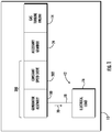
- FIG. 1 a partial view of an example of a generator assembly constructed in accordance with the disclosure is shown in FIG. 1 and is designated generally by reference character 100.
- FIGS. 2-8 Other embodiments of generator assemblies, integrated drive generators, and methods of making generator assemblies in accordance with the present disclosure, or aspects thereof, are provided in FIGS. 2-8 , as will be described.
- the systems and methods described herein can be used to limit (or close entirely) clearances between bearing assemblies and bearing support structures in rotating machines, such as in integrated drive generators for aircraft electrical systems, though the present disclosure is not limited to integrated drive generators or to generators assemblies in general.
- a vehicle 10 e.g., an aircraft
- the vehicle 10 includes an electrical system 12, a gas turbine engine 14, and a generator assembly 100.
- the electrical system 12 includes the generator assembly 100, an electrical load 16, and a power bus 18.
- the electrical load 16 is connected to the generator assembly 100 by the power bus 18.
- the generator assembly 100 is operably associated with the gas turbine engine 14 and is configured to generate electrical power 20 using mechanical rotation 22 (shown in FIG. 2 ) communicated thereto by the gas turbine engine 14.
- the generator assembly 100 is operably associated with the gas turbine engine 14 through an accessory gearbox 24 to receive therethrough the mechanical rotation 22.
- the generator assembly 100 is operably associated with the gas turbine engine 14 through a constant speed drive 202 as an integrated drive generator 200. Although shown and described herein in generator assembly for an aircraft it is to be understood and appreciated that other types of generators can benefit from the present disclosure.
- the generator assembly 100 includes a housing 102, a stator winding 104, and a rotor 106.
- the generator assembly 100 also includes a magnetic element 108, a first bearing assembly 110, and a second bearing assembly 112.
- the housing 102 has an interior 114.
- the stator winding 104, the rotor 106, and magnetic element 108 are arranged within the interior 114 of the housing 102.
- the magnetic element 108, the first bearing assembly 110 and the second bearing assembly 112 are also arranged within the interior 114 of the housing 102.
- the stator winding 104 is electrically connected to the power bus 18 (shown in FIG 1 ) and is arranged with provide a flow of electric current.
- the stator winding 104 is electromagnetically coupled to the magnetic element 108 such that rotation of magnetic element 108 relative to the stator winding 104 induces a flow of electric current in the stator winding 104.
- the flow of electric current is an alternating current (AC) flow.
- the magnetic element 108 is fixed relative to the rotor 106.
- the magnetic element 108 includes a permanent magnet 116.
- the magnetic element 108 includes a winding 118. It is also contemplated that the magnetic element 108 can include both the permanent magnet 116 and the winding 118.
- the rotor 106 is supported for rotation about a rotation axis 120 within the interior 114 of the housing 102 by the first bearing assembly 110 and the second bearing assembly 112.
- the first bearing assembly 110 is a radial bearing assembly, e.g., a ball bearing assembly.
- the second bearing assembly 112 is a straight bearing assembly. Straight bearing assemblies allow the rotor 106 to slide axially in response to heating of the generator assembly 100 during operation, such as due to differential between elongation of the rotor 106 and the housing 102 during operation.
- a radial bearing assembly and a straight bearing assembly it is to be understood and appreciated that rotating machines having other types of bearing assemblies can also benefit from the present disclosure.
- the first bearing assembly 110 includes an inner race 122, an outer race 124, and a plurality of spherical elements 126.
- the inner race 122 is fixed in rotation relative to the rotor 106 for rotation with the rotor 106 about the rotation axis 120.
- the plurality of spherical elements 126 are distributed circumferentially about the inner race 122 and the rotation axis 120.
- the outer race 124 extends circumferentially about the inner race 122 and the plurality of spherical elements 126, and is configured for fixation relative to the housing 102.
- Fixation of the first bearing assembly 110 to the housing 102 is accomplished by a clamp 128, a bearing support structure 130, and a retainer 132.
- the outer race 124 can be an unbroken race, limiting load on the first bearing assembly 110 and thereby extending the expected service life of the first bearing assembly 110.
- the bearing support structure 130 is fixed within the interior 114 of the housing 102 and has a bearing seat 134.
- the bearing seat 134 radially bounds the first bearing assembly 110, extends thereabout, and seats thereon the first bearing assembly 110.
- a plurality of first fasteners 136 (shown in FIG. 2 ) extend through the bearing support structure 130 and threadably fixes the bearing support structure 130 to the housing 102 and about the rotation axis 120.
- the clamp 128 is arranged within the interior 114 of the housing 102 and has a bearing support structure seat 138.
- the bearing support structure seat 138 radially bounds the bearing support structure 130, extends about the bearing support structure 130, and seats thereon the bearing support structure 130.
- a plurality of second fasteners 140 extend though the retainer 132 and the housing 102 to threadably fix the clamp 128 against the bearing support structure 130 with the first bearing assembly 110 captive between the clamp 128 and the bearing support structure 130.
- a radial clearance 142 is defined between the outer race 124 and of the first bearing assembly 110 and the bearing support structure 130.
- the clearance 142 facilitates assembly of the generator assembly 100 by allowing the bearing support structure 130 to be fixed with the interior 114 of the housing 102 and receive thereon the rotor 106 and the first bearing assembly 110 with the clamp 128 mounted thereon.
- such clearances can, in some generator assemblies, limit reliability of the generator assembly. For example, clearances can allow the bearing assembly to become misaligned relative to the rotation axis, increasing the load exerted on the bearing assembly.
- Clearances can also reduce the stiffness provided by the bearing assembly, limiting the frequency spacing between the bearing assembly and the nominal speed of rotor such that dynamic loading of the bearing assembly, potentially reducing service life of the bearing assembly. And in some generators such clearances can allow the outer race to orbit relative to the generator stator - the orbiting in turn causing fretting wear occurring and/or generating debris, posing a foreign object damage hazard.
- To limit misalignment, increase stiffness, and/or present orbiting the generator assembly 100 includes the sleeve member 144.
- the sleeve member 144 is arranged radially between the first bearing assembly 110 the bearing support structure 130. More specifically, the sleeve member 144 is arranged between the outer race 124 of the first bearing assembly 110 and the bearing seat 134 of the bearing support structure 130 to limit (or close entirely) the radial clearance 142. Limiting (or closing entirely) the radial clearance 142 fixes the outer race 124 of the first bearing assembly 110 relative to the bearing support structure 130, reducing (or eliminating entirely) misalignment of the first bearing assembly 110 relative to the rotation axis 120, stiffening the first bearing assembly 110, and/or preventing orbiting of the outer race 124 relative to the bearing support structure 130.
- the radial clearance 142 be limited (or closed entirely) subsequent to the assembly of the rotor 106 (carrying the first bearing assembly 110 and the clamp 128 thereon), the radial clearance 142 thereby facilitating assembly of the generator assembly 100 prior to being limited (or closed entirely).
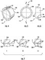
- the sleeve member 144 is shown. As shown in FIG. 4 , the sleeve member 144 includes an annular body 146 having an inboard edge 148, an outboard edge 150, and a defines a slot 152 extending between the inboard edge 148 and the outboard edge 150.
- the outboard edge 150 is arranged to abut the bearing support structure 130 (shown in FIG. 2 ) within the interior 114 (shown in FIG. 2 ) of the housing 102 (shown in FIG. 2 ) when the sleeve member 144 is installed within the generator assembly 100 (shown in FIG. 1 ).
- the inboard edge 148 is arranged to oppose the clamp 128 (shown in FIG.
- the slot 152 extend substantially in parallel with the rotation axis 120 (shown in FIG. 2 ) and between the bearing support structure 130 and the clamp 128.
- the annular body 146 extends circumferentially about the rotation axis 120 (shown in FIG. 2 ) such that the outboard edge 150 is radially offset from the rotation axis 120.
- the sleeve member 144 is clocked about the rotation axis 120 such that slot 152 is positioned above the rotation axis 120 relative to gravity.
- the sleeve member 144 can be seated within the interior 114 of the housing 102 such that the slot receives a pin 154, fixed relative to the housing 102, to fix position of the sleeve member 144 about the rotation axis 120 during assembly of the generator assembly 100 (shown in FIG. 1 ).
- the sleeve member 144 has a wedge-shaped profile 156.
- the wedge-shaped profile 156 extends axially between the inboard edge 148 and the outboard edge 150. It is contemplated that the wedge-shaped profile 156 taper between the inboard edge 148 and the outboard edge 150, the inboard edge 148 having a smaller surface area than the surface area of the outboard edge 150.
- the sleeve member 144 is formed from a metallic material 158.
- the metallic material 158 has a coefficient of thermal expansion that corresponds to the coefficient of thermal expansion of the first bearing assembly 110, the bearing support structure 130, and/or the clamp 128 such that clearance remains limited (or closed) during heating and cooling of the generator assembly 100 during operation.
- the sleeve member 144 seats radially between the first bearing assembly 110 and the bearing support structure 130. More specifically, the sleeve member 144 is radially interposed between the outer race 124 of the first bearing assembly 110 and the bearing support structure 130.
- the outer race 124 has radially-outer chamfer 160.
- the sleeve member 144 has a sleeve member axial width 162 that is smaller than a bearing member axial width 164.
- the radially-outer chamfer 160 is defined on an axially outer edge 166 of the outer race 124 such that a radially outer face 168 (shown in FIG. 4 ) of the sleeve member 144 is substantially parallel to the rotation axis 120.
- the radially-outer chamfer 160 cooperates with the wedge-shaped profile 156 such that, as the sleeve member 144 translates axially along the rotation axis 120 during assembly, the radial clearance 142 decreases in radial width (or closes entirely) such that the outer race 124 of the first bearing assembly 110 is fixed in rotation relative to the bearing support structure 130.
- seating the first bearing assembly 110 within the bearing support structure 130 causes the first bearing assembly 110 and the bearing support structure 130 to define a first gap width A between one another.
- translating the sleeve member 144 along the rotation axis 120 relative to the first bearing assembly 110 causes the first bearing assembly 110 and the bearing support structure 130 to define between a second gap width B between one another, the second gap width B larger than the first gap width A - limiting the radial clearance 142 between the first bearing assembly 110 and the bearing support structure 130.
- the radial clearance 142 is closed by translating the sleeve member 144 along the rotation axis 120 such that the first bearing assembly 110 and the bearing support structure 130 define a third gap width between one another, the third gap width C larger than the second gap width B.
- a method 300 of making a generator assembly e.g., the generator assembly 100 (shown in FIG. 1 ), is shown.
- the method 300 includes fixing a bearing support structure within the interior of a housing for a generator assembly, e.g., the bearing support structure 130 (shown in FIG. 2 ) within the interior 114 (shown in FIG. 2 ) of the housing 102 (shown in FIG. 2 ).
- Fixation can be accomplished by fastening the bearing support structure within the interior of the housing, e.g., with the plurality of first fasteners 136 (shown in FIG. 2 ).
- the method 300 also includes supporting a rotor carrying a magnetic element about a rotation axis within the housing, e.g., the rotor 106 (shown in FIG. 2 ) carrying the magnetic element 108 (shown in FIG. 2 ).
- a clamp e.g., the clamp 128 (shown in FIG. 2 ) is positioned about the rotor, as shown with box 222.
- An inner race of bearing assembly, the inner race 122 (shown in FIG. 3 ) of the first bearing assembly 110 (shown in FIG. 2 ), is fixed to the rotor such that the inner race is fixed in rotation relative to the rotor, as shown with box 224.
- the rotor including the clamp and the bearing assembly, is positioned within the housing such that the bearing assembly is arranged radially between the rotor and the bearing support structure with a clearance, e.g., the radial clearance 142 (shown in FIG. 3 ), is defined therebetween, as shown with box 326.
- a clearance e.g., the radial clearance 142 (shown in FIG. 3 ) is defined therebetween, as shown with box 326.
- a sleeve member e.g., the sleeve member 144 (shown in FIG. 3 ), is arranged radially between the bearing assembly and the bearing support structure.
- the sleeve member 144 is translated along the rotation axis relative to the bearing assembly, as shown with box 340.
- the sleeve member limits the clearance defined between the bearing assembly and the bearing support structure, as shown with box 350, e.g., by making a radial distance between the bearing assembly and the bearing support structure smaller.
- the clearance between the bearing assembly and the bearing support structure is closed, e.g., such that no radial distance is defined between the bearing assembly and the bearing support structure, as shown by box 352.
- closing the clearance by translating the sleeve member relative to the bearing assembly can create an interference fit between the sleeve member and either (or both) the bearing assembly and bearing support structure.
- Rotating machines commonly employ bearings to support rotary components for rotation relative to stationary components.
- there can be clearance between the bearing and the stationary portion of the rotating machine the clearance enabling assembly of the rotating machine.
- While generally acceptable for its intended purpose clearance between the bearing and stationary components of the rotating machine increase eccentric loading of the bearing, potentially reducing the expect service life of the bearing.
- Clearance between the bearing and stationary components of the rotating machine can also result in misalignment of the bearing, also potentially limiting the expected service life of the bearing.
- clearance between the bearing and the stationary components can also reduce bearing life due to misalignment and/or stiffness variation in intermediate structures supporting the bearing relative to other stationary structures.
- a portion of clearance between the bearing and the stationary structure of a rotating machine is closed subsequent to assembly of the rotor within the stator of the rotating machine.
- sleeve is arranged between the bearing and the stator of the rotating machine.
- the sleeve can be closed under outside and opened under inside pressure such that the sleeve diameter can be changed, i.e., be made smaller or larger, depending upon the pressure applied to the sleeve.
- the sleeve diameter will self-adjust to the inner diameter of the bearing support.
- Self-adjustment can be accomplished, for example, by clamping the sleeve between the stationary structure and a retaining plate. It also contemplated that, in accordance with certain examples, that the material forming the sleeve be selected such that thermal expansion of the sleeve corresponds, e.g., matches, that of thermal expansion of the bearing.
- Technical effects of the present disclosure can include limiting (or preventing entirely) distortion of the outer race of the bearing.
- Technical effects also include delaying (or preventing entirely) the tendency of the bearing to orbit within, and frictionally against, the seat defined by the stationary structure - limiting (or preventing entirely) the generation of debris from the orbiting which can otherwise present a foreign object damage hazard to the rotating machine.
- Technical effects additionally the employment of bearings having unbroken (non-broken) outer races.
Landscapes
- Engineering & Computer Science (AREA)
- General Engineering & Computer Science (AREA)
- Mechanical Engineering (AREA)
- Power Engineering (AREA)
- Motor Or Generator Frames (AREA)
- Connection Of Motors, Electrical Generators, Mechanical Devices, And The Like (AREA)
Applications Claiming Priority (1)
| Application Number | Priority Date | Filing Date | Title |
|---|---|---|---|
| US16/694,548 US11268575B2 (en) | 2019-11-25 | 2019-11-25 | Generator assemblies, integrated drive generators, and methods of making generator assemblies |
Publications (1)
| Publication Number | Publication Date |
|---|---|
| EP3826149A1 true EP3826149A1 (de) | 2021-05-26 |
Family
ID=73059703
Family Applications (1)
| Application Number | Title | Priority Date | Filing Date |
|---|---|---|---|
| EP20205643.8A Pending EP3826149A1 (de) | 2019-11-25 | 2020-11-04 | Generatoranordnungen, integrierte antriebsgeneratoren und verfahren zur herstellung von generatoranordnungen |
Country Status (2)
| Country | Link |
|---|---|
| US (2) | US11268575B2 (de) |
| EP (1) | EP3826149A1 (de) |
Families Citing this family (2)
| Publication number | Priority date | Publication date | Assignee | Title |
|---|---|---|---|---|
| US11268575B2 (en) | 2019-11-25 | 2022-03-08 | Hamilton Sundstrand Corporation | Generator assemblies, integrated drive generators, and methods of making generator assemblies |
| CN114215854A (zh) * | 2021-12-20 | 2022-03-22 | 北京交通大学 | 一种多磁源磁流体密封装置 |
Citations (6)
| Publication number | Priority date | Publication date | Assignee | Title |
|---|---|---|---|---|
| DE880235C (de) * | 1951-06-07 | 1953-06-18 | Carl Obermann | Einrichtung zur Befestigung von Waelzlagern an Lagertraegern |
| US4315442A (en) * | 1980-02-15 | 1982-02-16 | Sundstrand Corporation | Aircraft generator starter-drive |
| JPS62196423A (ja) * | 1986-02-24 | 1987-08-29 | Fuji Electric Co Ltd | 軸受装置 |
| FR2729442A1 (fr) * | 1995-01-17 | 1996-07-19 | Valeo Equip Electr Moteur | Perfectionnements aux paliers a roulement pour machines tournantes telles les alternateurs de vehicule automobile |
| US5947612A (en) * | 1998-03-02 | 1999-09-07 | Ford Motor Company | Bearing retention for a rotating machine |
| EP2093439A1 (de) * | 2008-02-25 | 2009-08-26 | Hamilton Sundstrand Corporation | Kegelstumpfförmiges Kugellager und vorgespannte Kugellageranordnungen |
Family Cites Families (13)
| Publication number | Priority date | Publication date | Assignee | Title |
|---|---|---|---|---|
| US851419A (en) * | 1905-06-15 | 1907-04-23 | Henry Hees | Ball-bearing. |
| DE3447150A1 (de) * | 1984-12-22 | 1986-07-10 | FAG Kugelfischer Georg Schäfer KGaA, 8720 Schweinfurt | Zweireihige schraeglagerung in 0-anordnung |
| DE3447148C1 (de) * | 1984-12-22 | 1986-08-28 | Kugelfischer G Schaefer & Co | Zweireihige Schraegkugellagerung in O-Anordnung |
| JPH0756598Y2 (ja) * | 1989-09-27 | 1995-12-25 | 松下電器産業株式会社 | 歯車減速機付電動機 |
| DE19645530C2 (de) * | 1996-11-05 | 1999-12-16 | Freudenberg Carl Fa | Wälzlager |
| US7448952B2 (en) | 2003-05-09 | 2008-11-11 | Gkn Driveline North America, Inc. | Light weight low angle fixed constant velocity joint and improved packaging |
| US7877043B2 (en) | 2004-09-22 | 2011-01-25 | Ntn Corporation | Constant-velocity joint and image-forming device |
| US20140219598A1 (en) | 2012-10-02 | 2014-08-07 | Andrew P. Grosskopf | Variable frequency generator input shaft bearing |
| US9410611B2 (en) | 2014-01-06 | 2016-08-09 | Hamilton Sundstrand Corporation | Carrier shaft set |
| US10385822B2 (en) | 2014-09-26 | 2019-08-20 | Aktiebolaget Skf | Wind turbine rotor shaft arrangement |
| US20190186598A1 (en) | 2015-12-30 | 2019-06-20 | General Electric Company | Apparatus and system for thin rim planet gear for aircraft engine power gearbox |
| CN108258870A (zh) * | 2016-12-29 | 2018-07-06 | 德昌电机(深圳)有限公司 | 电机及电机磁芯 |
| US11268575B2 (en) | 2019-11-25 | 2022-03-08 | Hamilton Sundstrand Corporation | Generator assemblies, integrated drive generators, and methods of making generator assemblies |
-
2019
- 2019-11-25 US US16/694,548 patent/US11268575B2/en active Active
-
2020
- 2020-11-04 EP EP20205643.8A patent/EP3826149A1/de active Pending
-
2022
- 2022-01-27 US US17/585,807 patent/US11808304B2/en active Active
Patent Citations (6)
| Publication number | Priority date | Publication date | Assignee | Title |
|---|---|---|---|---|
| DE880235C (de) * | 1951-06-07 | 1953-06-18 | Carl Obermann | Einrichtung zur Befestigung von Waelzlagern an Lagertraegern |
| US4315442A (en) * | 1980-02-15 | 1982-02-16 | Sundstrand Corporation | Aircraft generator starter-drive |
| JPS62196423A (ja) * | 1986-02-24 | 1987-08-29 | Fuji Electric Co Ltd | 軸受装置 |
| FR2729442A1 (fr) * | 1995-01-17 | 1996-07-19 | Valeo Equip Electr Moteur | Perfectionnements aux paliers a roulement pour machines tournantes telles les alternateurs de vehicule automobile |
| US5947612A (en) * | 1998-03-02 | 1999-09-07 | Ford Motor Company | Bearing retention for a rotating machine |
| EP2093439A1 (de) * | 2008-02-25 | 2009-08-26 | Hamilton Sundstrand Corporation | Kegelstumpfförmiges Kugellager und vorgespannte Kugellageranordnungen |
Also Published As
| Publication number | Publication date |
|---|---|
| US20220145938A1 (en) | 2022-05-12 |
| US11268575B2 (en) | 2022-03-08 |
| US20210156430A1 (en) | 2021-05-27 |
| US11808304B2 (en) | 2023-11-07 |
Similar Documents
| Publication | Publication Date | Title |
|---|---|---|
| US5921683A (en) | Bearing arrangement for air cycle machine | |
| US6491497B1 (en) | Method and apparatus for supporting rotor assemblies during unbalances | |
| CN101344036B (zh) | 涡轮机 | |
| US6325546B1 (en) | Fan assembly support system | |
| US8167531B2 (en) | Method and apparatus for supporting rotor assemblies during unbalances | |
| CA2934668C (en) | Bearing assembly for supporting a rotor shaft of a gas turbine engine | |
| US11808304B2 (en) | Generator assemblies, integrated drive generators, and methods of making generator assemblies | |
| US6783319B2 (en) | Method and apparatus for supporting rotor assemblies during unbalances | |
| CN104254699B (zh) | 滚子轴承组以及对应的旋转机器 | |
| KR102792937B1 (ko) | 전기 기계 조립체 및 회전자를 고정자에 록킹하기 위한 방법 | |
| EP2412080B1 (de) | Lageranordnung | |
| US20140154058A1 (en) | Rotating assemblies of turbomachinery, foil journal bearing assemblies thereof, and methods for producing journals of the foil journal bearing assemblies | |
| US11421734B2 (en) | Active radial magnetic bearing assembly with internal sensors | |
| EP3513043B1 (de) | Ein radialer strömungsgasturbinengenerator | |
| US20160172931A1 (en) | Alternator rotor to stator integrated hrdrodynamic bearing | |
| EP3457545B1 (de) | Segmentierte elektrische maschine | |
| US4827165A (en) | Integrated diode package | |
| US20200123930A1 (en) | Turbocharger bearing assembly and method for providing the same | |
| EP3490107A1 (de) | Generatorstatoren und verfahren zur herstellung von generatorstatoren | |
| US5610500A (en) | Method of converting turbine driven generator into a synchronous condenser | |
| US20070025850A1 (en) | Non-concentric rings for reduced turbo-machinery operating clearances | |
| US10330154B2 (en) | Bug roller bearing outer race assembly | |
| EP4667762A1 (de) | Rolle und rollenlager | |
| GB2025153A (en) | Thermal expansion compensating bearings in electric machines | |
| US20180003077A1 (en) | Turbocharger bearing assembly and method for providing the same |
Legal Events
| Date | Code | Title | Description |
|---|---|---|---|
| PUAI | Public reference made under article 153(3) epc to a published international application that has entered the european phase |
Free format text: ORIGINAL CODE: 0009012 |
|
| STAA | Information on the status of an ep patent application or granted ep patent |
Free format text: STATUS: THE APPLICATION HAS BEEN PUBLISHED |
|
| AK | Designated contracting states |
Kind code of ref document: A1 Designated state(s): AL AT BE BG CH CY CZ DE DK EE ES FI FR GB GR HR HU IE IS IT LI LT LU LV MC MK MT NL NO PL PT RO RS SE SI SK SM TR |
|
| STAA | Information on the status of an ep patent application or granted ep patent |
Free format text: STATUS: REQUEST FOR EXAMINATION WAS MADE |
|
| 17P | Request for examination filed |
Effective date: 20211125 |
|
| RBV | Designated contracting states (corrected) |
Designated state(s): AL AT BE BG CH CY CZ DE DK EE ES FI FR GB GR HR HU IE IS IT LI LT LU LV MC MK MT NL NO PL PT RO RS SE SI SK SM TR |
|
| STAA | Information on the status of an ep patent application or granted ep patent |
Free format text: STATUS: EXAMINATION IS IN PROGRESS |
|
| 17Q | First examination report despatched |
Effective date: 20240422 |