EP3826405B1 - Procédé et appareil de transmission d'informations, terminal et dispositif de réseau - Google Patents
Procédé et appareil de transmission d'informations, terminal et dispositif de réseau Download PDFInfo
- Publication number
- EP3826405B1 EP3826405B1 EP18934826.1A EP18934826A EP3826405B1 EP 3826405 B1 EP3826405 B1 EP 3826405B1 EP 18934826 A EP18934826 A EP 18934826A EP 3826405 B1 EP3826405 B1 EP 3826405B1
- Authority
- EP
- European Patent Office
- Prior art keywords
- network device
- terminal
- rrc
- message
- rrc message
- Prior art date
- Legal status (The legal status is an assumption and is not a legal conclusion. Google has not performed a legal analysis and makes no representation as to the accuracy of the status listed.)
- Active
Links
Images


Classifications
-
- H—ELECTRICITY
- H04—ELECTRIC COMMUNICATION TECHNIQUE
- H04W—WIRELESS COMMUNICATION NETWORKS
- H04W76/00—Connection management
- H04W76/20—Manipulation of established connections
- H04W76/27—Transitions between radio resource control [RRC] states
-
- H—ELECTRICITY
- H04—ELECTRIC COMMUNICATION TECHNIQUE
- H04W—WIRELESS COMMUNICATION NETWORKS
- H04W72/00—Local resource management
- H04W72/50—Allocation or scheduling criteria for wireless resources
- H04W72/56—Allocation or scheduling criteria for wireless resources based on priority criteria
-
- H—ELECTRICITY
- H04—ELECTRIC COMMUNICATION TECHNIQUE
- H04W—WIRELESS COMMUNICATION NETWORKS
- H04W24/00—Supervisory, monitoring or testing arrangements
- H04W24/08—Testing, supervising or monitoring using real traffic
-
- H—ELECTRICITY
- H04—ELECTRIC COMMUNICATION TECHNIQUE
- H04W—WIRELESS COMMUNICATION NETWORKS
- H04W24/00—Supervisory, monitoring or testing arrangements
- H04W24/10—Scheduling measurement reports ; Arrangements for measurement reports
-
- H—ELECTRICITY
- H04—ELECTRIC COMMUNICATION TECHNIQUE
- H04W—WIRELESS COMMUNICATION NETWORKS
- H04W76/00—Connection management
- H04W76/10—Connection setup
- H04W76/19—Connection re-establishment
-
- H—ELECTRICITY
- H04—ELECTRIC COMMUNICATION TECHNIQUE
- H04W—WIRELESS COMMUNICATION NETWORKS
- H04W76/00—Connection management
- H04W76/10—Connection setup
- H04W76/15—Setup of multiple wireless link connections
Definitions
- the embodiments of the present application relate to the field of mobile communication technology, and more specifically, to an information transmission method and apparatus, a terminal, and a network device.
- the network side supports Dual Connectivity (DC), or Multi Connectivity (MC).
- DC Dual Connectivity
- MC Multi Connectivity
- SN Secondary Node
- RRC Radio Resource Control
- CN105992393A discloses an auxiliary base station establishing method, comprising the steps of using a master base station to send an auxiliary base station increase request message to a base station allowed to be used as the auxiliary base station; and using the master base station to receive an auxiliary base station increase response message, wherein the auxiliary bearing or auxiliary cell configuration information of the UE is carried in the auxiliary base station increase response message.
- CN105992393A further discloses an auxiliary base station establishing method, comprising the steps of using the master base station to send the auxiliary base station increase request message to the base station, wherein the auxiliary base station increase request message contains the information used for determining whether the base station is allowed to be used as the auxiliary base station; and if the base station is allowed to be used as the auxiliary base station, using the master base station to receive the auxiliary base station increase response message from the base station, otherwise, using the master base station to receive an auxiliary base station increase failure message from the base station.
- SAMSUNG "Suspension of UE to RRC_INACTIVE in MR dual connectivity", 3GPP DRAFT, R2-1801417, XP051386826, relates to discussions about the SDAP/PDCP configures in the SCG for UE transition to inactive state while DC is configured, without requiring larger specification change, where upon transition to the INACTIVE state it is possible to consider UE re-configuration scenarios.
- the embodiments of the present application provide an information transmission method and apparatus, a terminal, and a network device.
- a terminal provided by an embodiment of the present application includes a processor and a memory.
- the memory is configured to store a computer program
- the processor is configured to call and run the computer program stored in the memory, and execute the information transmission method above.
- a network device provided by an embodiment of the present application includes: a processor and a memory.
- the memory is configured to store a computer program
- the processor is configured to call and run the computer program stored in the memory, and execute the information transmission method above.
- GSM Global System of Mobile communication
- CDMA Code Division Multiple Access
- WCDMA Wideband Code Division Multiple Access
- GPRS General Packet Radio Service
- LTE Long Term Evolution
- FDD Frequency Division Duplex
- TDD Time Division Duplex
- UMTS Universal Mobile Telecommunication System
- WiMAX Worldwide Interoperability for Microwave Access
- the communication system 100 may include a network device 110, and the network device 110 may be a device that communicates with a terminal 120 (or called a communication terminal or a terminal).
- the network device 110 may provide communication coverage for a specific geographic area, and may communicate with the terminal located in the coverage area.
- the network device 110 may be a Base Transceiver Station (BTS) in the GSM system or the CDMA system, or a NodeB (NB) in the WCDMA system, or an Evolutional Node B (eNB or eNodeB) in the LTE system, or a wireless controller in Cloud Radio Access Network (CRAN), or the network device may be a mobile switching center, a relay station, an access point, a vehicle-mounted device, a wearable device, a hub, a switch, a bridge, a router, a network side device in 5G network, or a network device in future evolving Public Land Mobile Network (PLMN), etc.
- BTS Base Transceiver Station
- NB NodeB
- eNB or eNodeB Evolutional Node B
- CRAN Cloud Radio Access Network
- the network device may be a mobile switching center, a relay station, an access point, a vehicle-mounted device, a wearable device, a hub, a switch, a bridge, a router,
- the communication system 100 also includes at least one terminal 120 located within the coverage area of the network device 110.
- the "Terminal” as used herein includes, but is not limited to, a connection via a wired line, such as a connection via Public Switched Telephone Networks (PSTN), a Digital Subscriber Line (DSL), a digital cable and a direct cable; and/or another data connection/network; and/or via a wireless interface, such as cellular network, Wireless Local Area Network (WLAN), digital television network such as DVB-H network, satellite network and an AM-FM broadcast transmitter; and/or an apparatus of another terminal set to receive/send communication signals; and/or an Internet of things (IOT) device.
- PSTN Public Switched Telephone Networks
- DSL Digital Subscriber Line
- WLAN Wireless Local Area Network
- IOT Internet of things
- the terminal set to communicate through the wireless interface may be referred to as "a wireless communication terminal", "a wireless terminal” or "a mobile terminal".
- the mobile terminal includes, but is not limited to, a satellite or cellular phone; a Personal Communications System (PCS) terminal that may combine a cellular radiophone with data processing, fax, and data communication capabilities; a PDA that may include a radiophone, a pager, an Internet/Intranet access, a web browser, a note, a calendar, and/or a Global Positioning System (GPS) receiver; and a conventional laptop and/or palmtop receiver or other electronic devices including a radiophone transceiver.
- PCS Personal Communications System
- GPS Global Positioning System
- the terminal may refer to an access terminal, User Equipment (UE), a subscriber unit, a subscriber station, a mobile station, a mobile platform, a remote station, a remote terminal, a mobile device, a user terminal, a terminal, a wireless communication device, a user agent or a user apparatus.
- the access terminal may be the cellular phone, a cordless telephone, a Session Initiation Protocol (SIP) phone, a Wireless Local Loop (WLL) station, the Personal Digital Assistant (PDA), a handheld device, a computing device having wireless connection functions or other processing device connected to a wireless modem, a vehicle-mounted device, a wearable device, a terminal in the 5G network or a terminal in the future evolving PLMN, etc.
- SIP Session Initiation Protocol
- WLL Wireless Local Loop
- PDA Personal Digital Assistant
- D2D Device to Device
- the 5G system or the 5G network may also be referred to as a New Radio (NR) system or NR network.
- NR New Radio
- Fig. 1 illustrates schematically one network device and two terminals.
- the communication system 100 may include a plurality of network devices, and other number of terminals may be included within the coverage of each network device, which are not limited in the embodiments of the present application.
- the communication system 100 may also include a network controller, a mobile management entity and other network entities, which are not limited in the embodiments of the present application.
- a device with communication functions in the network/system in the embodiments of the present application may be referred to as a communication device.
- the communication device may include the network device 110 and the terminal 120 with communication functions, and the network device 110 and the terminal 120 may be specific devices described above, which will not be repeated here; and the communication device may also include other devices in the communication system 100, such as the network controller, the mobile management entity and other network entities, which are not limited in the embodiments of the present application.
- system and “network” herein are often used interchangeably herein.
- the term “and/or” herein is only used to describe an association relationship between associated objects, which represents that there may be three kinds of relationships. For example, A and/or B may represent three situations: A exists alone, A and B exist at the same time, and B exists alone.
- the character “/” herein generally represents that pre and post associated objects are in an "or” relationship.
- the technical solutions of the embodiments of the present application are mainly applied to a 5G mobile communication system.
- the technical solutions of the embodiments of the present application are not limited to the 5G mobile communication system, but can also be applied to other types of mobile communication systems.
- the main application scenarios of the 5G mobile communication technology are: Enhance Mobile Broadband (eMBB), Ultra Reliable Low Latency Communication (URLLC), and massive Machine Type Communication (mMTC).
- eMBB Enhance Mobile Broadband
- URLLC Ultra Reliable Low Latency Communication
- mMTC massive Machine Type Communication
- a new RRC state is defined, that is, a RRC_INACTIVE state. This state is different from a RRC_IDLE state and a RRC_CONNECTED state.
- the network side may configure the paging area of the Radio Access Network (RAN) for the UE through dedicated signaling, and the paging area of the RAN may be one or more cells.
- the UE moves in the area, it does not need to notify the network side, and it follows mobility behavior under idle condition, that is, a cell selection reselection principle.
- the UE moves out of the paging area configured by the RAN, it may trigger the UE to recover the RRC connection and re-obtain the paging area configured by the RAN.
- the base station (such as gNB) that keeps the connection between the RAN and the Core Network (CN) for the UE may trigger all cells in the paging area of the RAN to send paging messages to the UE, so that the UE in the INACTIVCE state can recover the RRC connection and receive data.
- the base station such as gNB
- CN Core Network
- the network side initiates the paging on RAN side to impel the UE enter the connection state.
- the UE itself initiates RAN location area update, such as periodic RAN location update or cross-area location update.
- RAN location area update such as periodic RAN location update or cross-area location update.
- the UE has a demand of uplink data transmission, which impels the UE to enter the connection state.
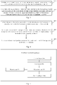
- Fig. 2 is a schematic diagram of a RRC connection resume procedure. As shown in Fig. 2 , the RRC connection resume procedure includes the following processes.
- step 101 the UE is in the INACTIVE state and needs to recover the RRC connection.
- step 102 the UE sends a preamble to the gNB.
- step 103 the gNB sends a Random Access Response (RAR) to the UE.
- RAR Random Access Response
- step 104 the UE sends a RRC resume request message (RRC Connection Resume Request) to the gNB.
- RRC resume request message RRC Connection Resume Request
- step 105 the gNB asks for UE context information from an anchor gNB.
- step 106 the gNB sends a RRC connection resume message (RRC Connection Resume) to the UE.
- RRC Connection Resume RRC Connection Resume
- step 107 the UE enters the RRC_CONNECTED state.
- step 108 the UE sends a RRC connection resume complete message (RRC Connection Resume Complete) to the gNB.
- Fig. 3 is a first schematic flowchart of an information transmission method provided by an embodiment of the present application. As shown in Fig. 3 , the information transmission method includes the following steps.
- a terminal sends a first RRC message to a first node, and receives a second RRC message sent by the first node, where the second RRC message carries configuration information of a second node.
- the terminal may be any device that can communicate with the network, such as a mobile phone, a tablet computer, a vehicle-mounted terminal, and a notebook.
- the terminal is a terminal configured with a DC mode or a MC mode
- the first node is a target master node
- the second node is an original secondary node stored on the first node side or a new secondary node re-determined by the first node.
- the configuration information of the second node includes bearer configuration information and physical layer resource configuration information.
- the first RRC message is a RRC connection resume request message
- the second RRC message is a RRC connection resume response message
- the third RRC message involved in the following step 302 is a RRC connection resume complete message.
- the first RRC message is a RRC reconfiguration request message
- the second RRC message is a RRC reconfiguration response message
- the third RRC message involved in the following step 302 is a RRC reconfiguration complete message.
- the UE configured with the DC mode sends the RRC connection resume request message to a target MN in the INACTIVE state, and then the target MN configures the UE with a SN and SN configuration information.
- the SN configuration information includes bearer configuration information and physical layer resource configuration information on SN side.
- the SN configured by the target MN for the UE may be an original SN stored on the target MN side in the INACTIVE state, or it may be a SN blindly configured by the target MN. Then, the target MN sends the SN configuration information to the UE in the RRC connection resume response message.
- the UE configured with the DC mode sends the RRC reconfiguration request message to the target MN in the INACTIVE state, and then the target MN configures the UE with the SN and the SN configuration information.
- the SN configuration information includes the bearer configuration information and the physical layer resource configuration information on the SN side.
- the SN configured by the target MN for the UE may be the original SN stored on the target MN side in the INACTIVE state, or it may be the SN blindly configured by the target MN. Then, the target MN sends the SN configuration information to the UE in the RRC reconfiguration response message.
- first RRC message is MSG3
- second RRC message is MSG4.
- the second RRC message further carries a first measurement threshold.
- step 302 the terminal determines whether the second node meets a target requirement according to a locally stored measurement result, and when the second node does not meet the target requirement, the terminal carries first indication information in a third RRC message sent to the first node, where the first indication information is used to indicate that the second node is not accepted by the terminal.
- the terminal determines whether the second node meets the target requirement according to the locally stored measurement result. 2) If the second RRC message carries the first measurement threshold, the terminal determines whether the second node meets the target requirement according to the locally stored measurement result and the first measurement threshold. Further, if the measurement result of the second node is greater than or equal to the first measurement threshold, it is determined that the second node meets the target requirement; and if the measurement result of the second node is less than the first measurement threshold, it is determined that the second node does not meet the target requirement.
- the UE obtains the configuration information of the SN (including PSCell configuration information) after receiving the MSG4, and the UE determines whether the SN is good enough (i.e. whether it meets the target requirement) according to the locally stored measurement result.
- the UE determines whether the SN meets the target requirement depends on realization of the UE, for example: the UE determines whether the SN meets the target requirement according to the quality of the SN.
- the UE obtains the configuration information of the SN (including the PSCell configuration information) after receiving the MSG4, and the UE determines whether the SN is good enough (that is, whether it meets the target requirement) according to the locally stored measurement result and the first measurement threshold, for example: if the measurement result of the PSCell is greater than or equal to the first measurement threshold, the SN meets the target requirement, and if the measurement result of the PSCell is less than the first measurement threshold, the SN does not meet the target requirement.
- the UE if the SN meets the target requirement, the UE considers that the SN can be used; and if the SN does not meet the target requirement, the UE considers that the SN cannot be used, and a new SN needs to be configured by the target MN
- the UE determines that the SN configured by the target MN does not meet the target requirement, it sends an indication to the network side in the third RRC message (i.e. MSG5) to indicate that the SN is not accepted by the UE.
- the third RRC message is the RRC connection resume complete message
- the third RRC message is the RRC reconfiguration complete message.
- the terminal releases the second node and the configuration information of the second node, and correspondingly, the first indication information is also used to indicate the terminal to release the configuration information of the second node.
- the UE releases the SN, and releases the bearer configuration information and the physical layer resource configuration information on the SN side.
- the target MN releases the SN if the above indication is included in the MSG 5. According to the situation, the target MN decides whether to initiate the RRC connection reconfiguration message to configure a new SN and configuration information (including bearer configuration information and physical layer resource configuration information) on the SN side.
- the target MN can release the bearer on the SN side directly; and if the bearer on the SN side has the service demand, the target MN may configure a new SN and SN configuration information, or the target MN may configure the bearer on the SN side as a bearer on the MN side.
- the target MN may configure it based on a measurement report reported by the UE, so that the SN that can be configured may meet the requirement of the UE, that is, it can be used by the UE.
- Fig. 4 is a second schematic flowchart of an information transmission method provided by an embodiment of the present application. As shown in Fig. 4 , the information transmission method includes the following steps.
- a first node receives a first RRC message sent by a terminal, and sends a second RRC message to the terminal, where the second RRC message carries configuration information of a second node.
- the terminal may be any device that can communicate with the network, such as a mobile phone, a tablet computer, a vehicle-mounted terminal, and a notebook.
- the terminal is a terminal configured with a DC mode or a MC mode
- the first node is a target master node
- the second node is an original secondary node stored on the first node side or a new secondary node re-determined by the first node.
- the configuration information of the second node includes bearer configuration information and physical layer resource configuration information.
- the first RRC message is a RRC connection resume request message
- the second RRC message is a RRC connection resume response message
- the third RRC message involved in the following step 302 is a RRC connection resume complete message.
- the first RRC message is a RRC reconfiguration request message
- the second RRC message is a RRC reconfiguration response message
- the third RRC message involved in the following step 302 is a RRC reconfiguration complete message.
- the UE configured with the DC mode sends the RRC connection resume request message to a target MN in the INACTIVE state, and then the target MN configures the UE with a SN and SN configuration information.
- the SN configuration information includes bearer configuration information and physical layer resource configuration information on SN side.
- the SN configured by the target MN for the UE may be an original SN stored on target MN side in the INACTIVE state, or may be a SN blindly configured by the target MN. Then, the target MN sends the SN configuration information to the UE in the RRC connection resume response message.
- the UE configured with the DC mode sends the RRC reconfiguration request message to the target MN in the INACTIVE state, and then the target MN configures the UE with the SN and the SN configuration information.
- the SN configuration information includes the bearer configuration information and the physical layer resource configuration information on the SN side.
- the SN configured by the target MN for the UE may be the original SN stored on the target MN side in the INACTIVE state, or may be the SN blindly configured by the target MN. Then, the target MN sends the SN configuration information to the UE in the RRC reconfiguration response message.
- first RRC message is MSG3
- second RRC message is MSG4.
- the second RRC message further carries a first measurement threshold.
- the second RRC message further carries a first measurement threshold; and the first measurement threshold is used by the terminal to determine whether the second node meets a target requirement in combination with a measurement result of the second node.
- step 402 the first node receives a third RRC message sent by the terminal, and determines whether the third RRC message carries first indication information, where the first indication information is used to indicate that the second node is not accepted by the terminal.
- the terminal determines whether the second node meets the target requirement according to a locally stored measurement result, and if the second node does not meet the target requirement, the terminal carries the first indication information in the third RRC message sent to the first node, the first indication information being used to indicate that the second node is not accepted by the terminal.
- the terminal determines whether the second node meets the target requirement according to the locally stored measurement result. 2) If the second RRC message carries the first measurement threshold, the terminal determines whether the second node meets the target requirement according to the locally stored measurement result and the first measurement threshold. Further, if the measurement result of the second node is greater than or equal to the first measurement threshold, it is determined that the second node meets the target requirement; and if the measurement result of the second node is less than the first measurement threshold, it is determined that the second node does not meet the target requirement.
- the UE obtains the configuration information of the SN (including PSCell configuration information) after receiving the MSG4, and the UE determines whether the SN is good enough (i.e. whether it meets the target requirement) according to the locally stored measurement result.
- the UE determines whether the SN meets the target requirement depends on realization of the UE, for example: the UE determines whether the SN meets the target requirement according to the quality of the SN.
- the UE obtains the configuration information of the SN (including the PSCell configuration information) after receiving the MSG4, and the UE determines whether the SN is good enough (that is, whether it meets the target requirement) according to the locally stored measurement result and the first measurement threshold. For example: if the measurement result of the PSCell is greater than or equal to the first measurement threshold, the SN meets the target requirement, and if the measurement result of the PSCell is less than the first measurement threshold, the SN does not meet the target requirement.
- the UE if the SN meets the target requirement, the UE considers that the SN can be used; and if the SN does not meet the target requirement, the UE considers that the SN cannot be used, and a new SN needs to be configured by the target MN
- the UE determines that the SN configured by the target MN does not meet the target requirement, it sends an indication to the network side in the third RRC message (i.e. MSG5) to indicate that the SN is not accepted by the UE.
- the third RRC message is the RRC connection resume complete message
- the third RRC message is the RRC reconfiguration complete message.
- step 403 the first node releases the configuration information of the second node if the third RRC message carries the first indication information.
- the terminal releases the second node and the configuration information of the second node, and correspondingly, the first indication information is also used to indicate the terminal to release the configuration information of the second node. For example: if the SN configured by the target MN does not meet the target requirement, the UE releases the SN, and releases the bearer configuration information and the physical layer resource configuration information on the SN side.
- the first node if there is a service demand on second node side, the first node carries configuration information of a third node in a fourth RRC message sent to the terminal, or, the first node configures a bearer on the second node side as a bearer on the first node side.
- the third node is a new secondary node re-determined by the first node, and the third node is different from the second node.
- the target MN after receiving the MSG 5, the target MN releases the SN if the above indication is included in the MSG 5. According to the situation, the target MN decides whether to initiate the RRC connection reconfiguration message to configure a new SN and configuration information (including bearer configuration information and physical layer resource configuration information) on SN side. For example: if a bearer on the SN side has no service demand, the target MN may release the bearer on the SN side directly; and if the bearer on the SN side has the service demand, the target MN may configure a new SN and SN configuration information, or the target MN may configure the bearer on the SN side as a bearer on the MN side.
- the target MN when configuring the new SN, the target MN may configure it based on a measurement report reported by the UE, so that the SN that can be configured may meet the requirement of the UE, that is, it can be used by the UE.
- Fig. 5 is a first schematic structure composition diagram of an information transmission apparatus provided by an embodiment of the present application, which is applied to a terminal. As shown in Fig. 5 , the apparatus includes:
- the second RRC message further carries a first measurement threshold.
- the determining unit 503 is configured to determine whether the second node meets the target requirement according to the locally stored measurement result and the first measurement threshold.
- the determining unit 503 is configured to determine that the second node meets the target requirement if the measurement result of the second node is greater than or equal to the first measurement threshold; and determine that the second node does not meet the target requirement if the measurement result of the second node is less than the first measurement threshold.
- the apparatus further includes:
- the terminal is a terminal configured with a DC mode
- the first node is a target master node
- the second node is an original secondary node stored on the first node side or a new secondary node re-determined by the first node.
- the first RRC message is a RRC connection resume request message
- the second RRC message is a RRC connection resume response message
- the third RRC message is a RRC connection resume complete message
- the first RRC message is a RRC reconfiguration request message
- the second RRC message is a RRC reconfiguration response message
- the third RRC message is a RRC reconfiguration complete message
- Fig. 6 is a second schematic structure composition diagram of an information transmission apparatus provided by an embodiment of the present application, which is applied to a first node. As shown in Fig. 6 , the apparatus includes:
- the second RRC message further carries a first measurement threshold; the first measurement threshold is used by the terminal to determine whether the second node meets a target requirement in combination with a measurement result of the second node.
- the first indication information is further used to indicate the terminal to release the configuration information of the second node.
- the apparatus further includes: a processing unit 605, configured to, if there is a service demand on the second node side, carry configuration information of a third node in a fourth RRC message sent to the terminal, or, configure a bearer on the second node side as a bearer on the first node side.
- a processing unit 605 configured to, if there is a service demand on the second node side, carry configuration information of a third node in a fourth RRC message sent to the terminal, or, configure a bearer on the second node side as a bearer on the first node side.
- the third node is a new secondary node re-determined by the first node, and the third node is different from the second node.
- the terminal is a terminal configured with a DC mode
- the first node is a target master node
- the second node is an original secondary node stored on the first node side or a new secondary node re-determined by the first node.
- the first RRC message is a RRC connection resume request message
- the second RRC message is a RRC connection resume response message
- the third RRC message is a RRC connection resume complete message
- the first RRC message is a RRC reconfiguration request message
- the second RRC message is a RRC reconfiguration response message
- the third RRC message is a RRC reconfiguration complete message
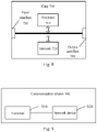
- Fig. 7 is a schematic structure diagram of a communication device 600 provided by an embodiment of the present application.
- the communication device may be a terminal or a network device, the communication device 600 shown in Fig. 7 includes a processor 610, and the processor 610 may call and run a computer program from a memory to implement the method in the embodiment of the present application.
- the communication device 600 may further include a memory 620.
- the processor 610 may call and run the computer program from the memory 620 to implement the method in the embodiment of the present application.
- the memory 620 may be a separate device independent of the processor 610, or it may also be integrated in the processor 610.
- the communication device 600 may further include a transceiver 630, which may be controlled by the processor 610 to communicate with other devices, and specifically, the transceiver 630 may send information or data to other devices or receive information or data sent by other devices.
- a transceiver 630 which may be controlled by the processor 610 to communicate with other devices, and specifically, the transceiver 630 may send information or data to other devices or receive information or data sent by other devices.
- the transceiver 630 may include a transmitter and a receiver.
- the transceiver 630 may further include an antenna, the number of which may be one or more.
- the communication device 600 may specifically be the network device in the embodiments of the present application, and the communication device 600 may implement corresponding processes implemented by the network device in each method in the embodiments of the present application, which will not be repeated here for the sake of brevity.
- the communication device 600 may be the mobile terminal/the terminal in the embodiments of the present application, and the communication device 600 may implement corresponding processes implemented by the mobile terminal/the terminal in each method in the embodiments of the present application, which will not be repeated here for the sake of brevity.
- Fig. 8 is a schematic structure diagram of a chip in an embodiment of the present application.
- the chip 700 shown in Fig. 8 includes a processor 710, and the processor 710 may call and run a computer program from a memory to implement the method in the embodiments of the present application.
- the chip 700 may further include a memory 720.
- the processor 710 may call and run the computer program from the memory 720 to implement the method in the embodiments of the present application.
- the memory 720 may be a separate device independent of the processor 710, or it may be integrated in the processor 710.
- the chip 700 may further include an input interface 730.
- the processor 710 may control the input interface 730 to communicate with other devices or chips, and specifically, the input interface 730 may obtain information or data sent by other devices or chips.
- the chip 700 may also include an output interface 740.
- the processor 710 may control the output interface 740 to communicate with other devices or chips, and specifically, the output interface 740 may output information or data to other devices or chips.
- the chip may be applied to the network device in the embodiments of the present application, and the chip may implement corresponding processes implemented by the network device in each method in the embodiments of the present application, which will not be repeated here for the sake of brevity.
- the chip may be applied to the mobile terminal/the terminal in the embodiments of the present application, and the chip may implement corresponding processes implemented by the mobile terminal/the terminal in each method in the embodiments of the present application, which will not be repeated here for the sake of brevity.
- chip mentioned in the embodiments of the present application may also be referred to as a system level chip, a system chip, a chip system or a system-on-chip, etc.
- Fig. 9 is a schematic block diagram of a communication system 900 provided by an embodiment of the present application. As shown in Fig. 9 , the communication system 900 includes a terminal 910 and a network device 920.
- the terminal 910 may be used to implement corresponding functions implemented by the terminal in the above methods, and the network device 920 may be used to implement corresponding functions implemented by the network device in the above methods, and will not be repeated here for the sake of brevity.
- the processor in the embodiments of the present application may be an integrated circuit chip with signal processing capability.
- each step of the above method embodiments may be completed by integrated logic circuits of hardware or instructions in software form in the processor.
- the above processor may be a general purpose processor, a Digital Signal Processor (DSP), an Application Specific Integrated Circuit (ASIC), a Field Programmable Gate Array (FPGA) or other programmable logic devices, discrete gates or transistor logic devices, discrete hardware components.
- DSP Digital Signal Processor
- ASIC Application Specific Integrated Circuit
- FPGA Field Programmable Gate Array
- Each method, step and logic block diagram disclosed in the embodiments of the present application may be implemented or executed.
- the general purpose processor may be a microprocessor processor or the processor may be any conventional processor, etc.
- the steps combining with the methods disclosed in the embodiments of the present application may be directly executed and completed by a hardware decoding processor or by the combination of hardware and software modules in a decoding processor.
- the software module can be located in a RAM, a flash memory, a read-only memory, a programmable read-only memory or an electrically erasable programmable memory, a register and other mature storage medium in this field.
- the storage medium is located in the memory, and the processor reads information in the memory and completes the steps of the above methods combined with its hardware.
- the memory in the embodiments of the present application may be a volatile memory or a non-volatile memory, or may include both the volatile memory and the non-volatile memory.
- the non-volatile memory may be the Read-Only Memory (ROM), the Programmable ROM (PROM), an Erasable PROM (EPROM), and the Electrically EPROM (EEPROM) or the flash memory.
- the volatile memory may be the Random Access Memory (RAM), which is used as an external cache.
- RAM Direct Rambus RAM
- SRAM Static RAM
- DRAM Dynamic RAM
- SDRAM Synchronous DRAM
- DDR SDRAM Double Data Rate SDRAM
- ESDRAM Enhanced SDRAM
- SLDRAM Synchlink DRAM
- DR RAM Direct Rambus RAM
- the memory in the embodiments of the present application may also be the static RAM (SRAM), the dynamic RAM (DRAM), the synchronous DRAM (SDRAM), the double data rate SDRAM (DDR SDRAM), the enhanced SDRAM (ESDRAM), the synch link DRAM (SLDRAM), and the Direct Rambus RAM (DR RAM), etc. That is to say, the memories in the embodiments of the present application are intended to include but not limited to these and any other suitable types of memories.
- SRAM static RAM
- DRAM dynamic RAM
- SDRAM synchronous DRAM
- DDR SDRAM double data rate SDRAM
- ESDRAM enhanced SDRAM
- SLDRAM synch link DRAM
- DR RAM Direct Rambus RAM
- An embodiment of the present application further provides a computer-readable storage medium for storing the computer program.
- the computer-readable storage medium may be applied to the network device in the embodiments of the present application, and the computer program may enable the omputer to execute the corresponding processes implemented by the network device in each method in the embodiments of the present application, which will not be repeated here for the sake of brevity.
- the computer-readable storage medium may be applied to the mobile terminal/the terminal in the embodiments of the present application, and the computer program may enable the computer to execute the corresponding processes implemented by the mobile terminal/the terminal in each method in the embodiments of the present application, which will not be repeated here for the sake of brevity.
- An embodiment of the present application further provides a computer program product, including a computer program instruction.
- the computer program product may be applied to the network device in the embodiments of the present application, and the computer program instruction may enable the computer to execute the corresponding processes implemented by the network device in each method in the embodiments of the present application, which will not be repeated here for the sake of brevity.
- the computer program product may be applied to the mobile terminal/the terminal in the embodiments of the present application, and the computer program instruction may enable the computer to excute the corresponding processes implemented by the mobile terminal/the terminal in each method in the embodiments of the present application, which will not be repeated here for the sake of brevity.
- An embodiment of the present application also provides a computer program.
- the computer program may be applied to the network device in the embodiments of the present application, and the computer program, when running on a computer, may enable the computer to execute the corresponding processes implemented by the network device in each method in the embodiments of the present application, which will not be repeated here for the sake of brevity.
- the computer program may be applied to the mobile terminal/the terminal in the embodiments of the present application, and the computer program, when running on a computer, may enable the computer to execute the corresponding processes implemented by the mobile terminal/the terminal in each method in the embodiments of the present application, which will not be repeated here for the sake of brevity.
- the units described as separate parts may or may not be physically separated, and parts displayed as units may be or may not be physical units, that is, they may be located in the same place or distributed over multiple network units. Part or all of the units can be selected according to actual needs to implement the purpose of the solution of the embodiments.
- each functional unit in each embodiment of the present application may be integrated in one processing unit, or each unit may physically exist independently, or two or more units may be integrated in one unit.
- the functions may be stored in a computer-readable storage medium if being implemented in the form of a software functional unit and sold or used as an independent product. Based on such understanding, the essence of the technical solutions of the present application, or the part contributing to the related art or a part of the technical solutions, may be embodied in the form of a software product.
- the computer software product is stored in a storage medium including a number of instructions such that a computer device (which may be a personal computer, a server, or a network device, etc.) performs all or a part of steps of the method described in each of the embodiments of the present disclosure.
- the foregoing storage medium includes: any medium that is capable of storing program codes such as a USB disk, a mobile hard disk, a read-only memory, a random access memory, a magnetic disk, or an optical disk.
Landscapes
- Engineering & Computer Science (AREA)
- Computer Networks & Wireless Communication (AREA)
- Signal Processing (AREA)
- Mobile Radio Communication Systems (AREA)
Claims (11)
- Procédé de transmission d'informations, le procédé comprenant :(301) envoi, par un terminal, d'un premier message de commande des ressources radio (RRC) à un premier dispositif de réseau, et réception, par le terminal, d'un deuxième message RRC envoyé par le premier dispositif de réseau, le deuxième message RRC incorporant des informations de configuration relatives à un deuxième dispositif de réseau ;le procédé étant caractérisé en ce qu'il comprend en outre :(302) détermination, par le terminal, si le deuxième dispositif de réseau répond ou non à une exigence cible selon un résultat de mesure stocké localement et, lorsque le deuxième dispositif de réseau ne répond pas à l'exigence cible, l'incorporation, par le terminal, de premières informations d'indication dans un troisième message RRC envoyé par le premier dispositif de réseau, les premières informations d'indication étant utilisées pour indiquer que le deuxième dispositif de réseau n'est pas accepté par le terminal,le premier message RRC étant un message de demande de reprise de connexion RRC, le deuxième message RRC étant un message de réponse de reprise de connexion RRC, et le troisième message RRC étant un message de reprise de connexion effectuée RRC ; ou,le premier message RRC étant un message de demande de reconfiguration RRC, le deuxième message RRC étant un message de réponse de reconfiguration RRC, et le troisième message RRC étant un message de reconfiguration de connexion effectuée RRC,le terminal étant un terminal configuré avec un mode double connectivité (DC), le premier dispositif de réseau étant un dispositif de réseau maître cible pour la double connectivité, et le deuxième dispositif de réseau étant un dispositif de réseau secondaire d'origine, une configuration du dispositif de réseau secondaire d'origine étant stockée côté premier dispositif de réseau, ou le deuxième dispositif de réseau étant un nouveau dispositif de réseau secondaire redéterminé par le premier dispositif de réseau, etles informations de configuration comprenant des informations de configuration de support et des informations de configuration de ressources de couche physique pour l'établissement d'une liaison secondaire.
- Procédé selon la revendication 1, dans lequel le deuxième message RRC incorpore en outre un premier seuil de mesure ; et
la (302) détermination, par le terminal, si le deuxième dispositif de réseau répond ou non à l'exigence cible selon le résultat de mesure stocké localement comprend :
la détermination, par le terminal, si le deuxième dispositif de réseau répond ou non à l'exigence cible selon le résultat de mesure stocké localement et le premier seuil de mesure. - Procédé selon la revendication 2, dans lequel la détermination, par le terminal, si le deuxième dispositif de réseau répond ou non à l'exigence cible selon le résultat de mesure stocké localement et le premier seuil de mesure comprend :la détermination que le deuxième dispositif de réseau répond à l'exigence cible si le résultat de mesure du deuxième dispositif de réseau est supérieur ou égal au premier seuil de mesure ; etla détermination que le deuxième dispositif de réseau ne répond pas à l'exigence cible si le résultat de mesure du deuxième dispositif de réseau est inférieur au premier seuil de mesure.
- Procédé selon l'une quelconque des revendications 1 à 3, comprenant en outre :la libération, par le terminal, des informations de configuration relatives au deuxième dispositif de réseau lorsque le deuxième dispositif de réseau ne répond pas à l'exigence cible ; etcorrélativement, les premières informations d'indication étant utilisées en outre pour indiquer au terminal de libérer les informations de configuration relatives au deuxième dispositif de réseau.
- Procédé de transmission d'informations, le procédé comprenant :(401) réception, par un premier dispositif de réseau, d'un premier message RRC envoyé par un terminal, et envoi, par le premier dispositif de réseau, d'un deuxième message RRC au terminal, le deuxième message RRC incorporant des informations de configuration relatives à un deuxième dispositif de réseau ;le procédé étant caractérisé en ce qu'il comprend en outre :(402) réception, par le premier dispositif de réseau, d'un troisième message RRC envoyé par le terminal, et détermination, par le premier dispositif de réseau, si le troisième message RRC incorpore ou non des premières informations d'indication, les premières informations d'indication étant utilisées pour indiquer que le deuxième dispositif de réseau n'est pas accepté par le terminal ; etlibération, par le premier dispositif de réseau, des informations de configuration relatives au deuxième dispositif de réseau lorsque le troisième message RRC incorpore les premières informations d'indication,le premier message RRC étant un message de demande de reprise de connexion RRC, le deuxième message RRC étant un message de réponse de reprise de connexion RRC, et le troisième message RRC étant un message de reprise de connexion effectuée RRC ; ou,le premier message RRC étant un message de demande de reconfiguration RRC, le deuxième message RRC étant un message de réponse de reconfiguration RRC, et le troisième message RRC étant un message de reconfiguration de connexion effectuée RRC,le terminal étant un terminal configuré avec un mode double connectivité (DC), le premier dispositif de réseau étant un dispositif de réseau maître cible pour la double connectivité, et le deuxième dispositif de réseau étant un dispositif de réseau secondaire d'origine, une configuration du dispositif de réseau secondaire d'origine étant stockée côté premier dispositif de réseau, ou le deuxième dispositif de réseau étant un nouveau dispositif de réseau secondaire redéterminé par le premier dispositif de réseau, etles informations de configuration comprenant des informations de configuration de support et des informations de configuration de ressources de couche physique pour l'établissement d'une liaison secondaire.
- Procédé selon la revendication 5, dans lequel le deuxième message RRC incorpore en outre un premier seuil de mesure ;
le premier seuil de mesure est utilisé par le terminal pour déterminer si le deuxième dispositif de réseau répond ou non à une exigence cible en association avec un résultat de mesure du deuxième dispositif de réseau. - Procédé selon la revendication 5 ou 6, dans lequel les premières informations d'indication sont utilisées en outre pour indiquer au terminal de libérer les informations de configuration relatives au deuxième dispositif de réseau.
- Procédé selon l'une quelconque des revendications 5 à 7, comprenant en outre :
lorsqu'un besoin de service existe côté deuxième dispositif de réseau, l'incorporation, par le premier dispositif de réseau, d'informations de configuration relatives à un troisième dispositif de réseau dans un quatrième message RRC envoyé au terminal, ou la configuration, par le premier dispositif de réseau, d'un support côté deuxième dispositif de réseau comme support côté premier deuxième dispositif de réseau. - Procédé selon la revendication 8, dans lequel le troisième dispositif de réseau est un nouveau dispositif de réseau secondaire redéterminé par le premier dispositif de réseau, et le troisième dispositif de réseau est différent du deuxième dispositif de réseau.
- Terminal, comprenant : un processeur et une mémoire, la mémoire étant configurée pour stocker un programme d'ordinateur, et le processeur étant configuré pour appeler et exécuter le programme d'ordinateur stocké dans la mémoire et exécuter le procédé selon l'une quelconque des revendications 1 à 4.
- Dispositif de réseau, comprenant : un processeur et une mémoire, la mémoire étant configurée pour stocker un programme d'ordinateur, et le processeur étant configuré pour appeler et exécuter le programme d'ordinateur stocké dans la mémoire et exécuter le procédé selon l'une quelconque des revendications 5 à 9.
Applications Claiming Priority (1)
| Application Number | Priority Date | Filing Date | Title |
|---|---|---|---|
| PCT/CN2018/108223 WO2020061995A1 (fr) | 2018-09-28 | 2018-09-28 | Procédé et appareil de transmission d'informations, terminal et dispositif de réseau |
Publications (3)
| Publication Number | Publication Date |
|---|---|
| EP3826405A1 EP3826405A1 (fr) | 2021-05-26 |
| EP3826405A4 EP3826405A4 (fr) | 2021-08-18 |
| EP3826405B1 true EP3826405B1 (fr) | 2023-01-25 |
Family
ID=69950904
Family Applications (1)
| Application Number | Title | Priority Date | Filing Date |
|---|---|---|---|
| EP18934826.1A Active EP3826405B1 (fr) | 2018-09-28 | 2018-09-28 | Procédé et appareil de transmission d'informations, terminal et dispositif de réseau |
Country Status (7)
| Country | Link |
|---|---|
| US (1) | US11653407B2 (fr) |
| EP (1) | EP3826405B1 (fr) |
| JP (1) | JP2022511289A (fr) |
| KR (1) | KR20210068403A (fr) |
| CN (2) | CN112804759B (fr) |
| AU (1) | AU2018443159A1 (fr) |
| WO (1) | WO2020061995A1 (fr) |
Families Citing this family (4)
| Publication number | Priority date | Publication date | Assignee | Title |
|---|---|---|---|---|
| AU2018443159A1 (en) | 2018-09-28 | 2021-03-25 | Guangdong Oppo Mobile Telecommunications Corp., Ltd. | Information transmission method and apparatus, and terminal and network device |
| CN114451031A (zh) | 2019-08-08 | 2022-05-06 | 谷歌有限责任公司 | 用于多无线电双连接的网络触发寻呼 |
| CN115334640B (zh) * | 2021-05-11 | 2025-02-07 | 大唐移动通信设备有限公司 | 辅助定位的方法、装置、存储介质及程序产品 |
| KR20240042727A (ko) * | 2022-09-26 | 2024-04-02 | 주식회사 블랙핀 | 무선 이동 통신 시스템에서 rrc_inactive 상태에서 연결을 재개하는 방법 및 장치 |
Family Cites Families (8)
| Publication number | Priority date | Publication date | Assignee | Title |
|---|---|---|---|---|
| CN102892081B (zh) * | 2011-07-22 | 2015-07-08 | 华为技术有限公司 | 业务重定向的方法、用户设备、接入网节点和系统 |
| CN105992393A (zh) * | 2015-01-29 | 2016-10-05 | 北京三星通信技术研究有限公司 | 建立辅基站的方法及设备 |
| CN113645618B (zh) * | 2015-08-20 | 2022-05-17 | 北京三星通信技术研究有限公司 | 一种ue的接入、切换和加密控制的方法与设备 |
| CN107548166B (zh) * | 2016-06-29 | 2020-06-23 | 中国移动通信有限公司研究院 | 配置多连接信令的方法、主基站、用户设备及通信系统 |
| US10849178B2 (en) * | 2016-09-22 | 2020-11-24 | Lg Electronics Inc. | Handling of conflict configuration in dual connectivity |
| CN108633018B (zh) * | 2017-03-23 | 2024-02-02 | 华为技术有限公司 | 配置方法、装置及系统 |
| CN108401537A (zh) * | 2018-02-11 | 2018-08-14 | 北京小米移动软件有限公司 | 设备内共存干扰协调方法、装置、用户设备及通信设备 |
| AU2018443159A1 (en) | 2018-09-28 | 2021-03-25 | Guangdong Oppo Mobile Telecommunications Corp., Ltd. | Information transmission method and apparatus, and terminal and network device |
-
2018
- 2018-09-28 AU AU2018443159A patent/AU2018443159A1/en not_active Abandoned
- 2018-09-28 CN CN202110040737.6A patent/CN112804759B/zh active Active
- 2018-09-28 EP EP18934826.1A patent/EP3826405B1/fr active Active
- 2018-09-28 CN CN201880094155.2A patent/CN112205055A/zh active Pending
- 2018-09-28 JP JP2021512222A patent/JP2022511289A/ja not_active Withdrawn
- 2018-09-28 KR KR1020217006955A patent/KR20210068403A/ko not_active Withdrawn
- 2018-09-28 WO PCT/CN2018/108223 patent/WO2020061995A1/fr not_active Ceased
-
2021
- 2021-02-09 US US17/171,884 patent/US11653407B2/en active Active
Also Published As
| Publication number | Publication date |
|---|---|
| KR20210068403A (ko) | 2021-06-09 |
| EP3826405A1 (fr) | 2021-05-26 |
| CN112205055A (zh) | 2021-01-08 |
| EP3826405A4 (fr) | 2021-08-18 |
| US11653407B2 (en) | 2023-05-16 |
| CN112804759A (zh) | 2021-05-14 |
| US20210168896A1 (en) | 2021-06-03 |
| AU2018443159A1 (en) | 2021-03-25 |
| CN112804759B (zh) | 2022-12-02 |
| JP2022511289A (ja) | 2022-01-31 |
| WO2020061995A1 (fr) | 2020-04-02 |
Similar Documents
| Publication | Publication Date | Title |
|---|---|---|
| US12096205B2 (en) | Method and apparatus for parameter configuration, network device, and terminal | |
| US11653407B2 (en) | Information transmission method and apparatus, and terminal and network device | |
| KR20210045349A (ko) | 정보 전송 방법, 장치 및 통신 디바이스 | |
| CN114303396B (zh) | 一种辅助信息处理方法、电子设备及存储介质 | |
| EP4132205A1 (fr) | Procédé et dispositif de transmission et de réception de données dans un état inactif, et équipement utilisateur | |
| US11856634B2 (en) | Method and device for controlling mobility of terminal, and terminal | |
| US11229079B2 (en) | Information configuration method and terminal | |
| EP3755031B1 (fr) | Procédé et appareil d'entretien de relation de voisinage, et dispositif de réseau | |
| US11963255B2 (en) | Method and apparatus for determining eDRX configuration parameters, and terminal | |
| CN112313979B (zh) | 一种信息传输方法及装置、网络设备 | |
| CN112715038A (zh) | 一种参数配置方法及装置、网络设备 | |
| CN112789891B (zh) | 无线通信方法、装置和终端设备 | |
| US20210160948A1 (en) | Method and apparatus for recovering rrc connection, and terminal |
Legal Events
| Date | Code | Title | Description |
|---|---|---|---|
| STAA | Information on the status of an ep patent application or granted ep patent |
Free format text: STATUS: THE INTERNATIONAL PUBLICATION HAS BEEN MADE |
|
| PUAI | Public reference made under article 153(3) epc to a published international application that has entered the european phase |
Free format text: ORIGINAL CODE: 0009012 |
|
| STAA | Information on the status of an ep patent application or granted ep patent |
Free format text: STATUS: REQUEST FOR EXAMINATION WAS MADE |
|
| 17P | Request for examination filed |
Effective date: 20210218 |
|
| AK | Designated contracting states |
Kind code of ref document: A1 Designated state(s): AL AT BE BG CH CY CZ DE DK EE ES FI FR GB GR HR HU IE IS IT LI LT LU LV MC MK MT NL NO PL PT RO RS SE SI SK SM TR |
|
| A4 | Supplementary search report drawn up and despatched |
Effective date: 20210715 |
|
| RIC1 | Information provided on ipc code assigned before grant |
Ipc: H04W 72/10 20090101AFI20210709BHEP Ipc: H04W 76/15 20180101ALI20210709BHEP |
|
| DAV | Request for validation of the european patent (deleted) | ||
| DAX | Request for extension of the european patent (deleted) | ||
| STAA | Information on the status of an ep patent application or granted ep patent |
Free format text: STATUS: EXAMINATION IS IN PROGRESS |
|
| 17Q | First examination report despatched |
Effective date: 20220405 |
|
| REG | Reference to a national code |
Ref country code: DE Ref legal event code: R079 Ref document number: 602018045867 Country of ref document: DE Free format text: PREVIOUS MAIN CLASS: H04W0072100000 Ipc: H04W0076270000 |
|
| GRAP | Despatch of communication of intention to grant a patent |
Free format text: ORIGINAL CODE: EPIDOSNIGR1 |
|
| STAA | Information on the status of an ep patent application or granted ep patent |
Free format text: STATUS: GRANT OF PATENT IS INTENDED |
|
| RIC1 | Information provided on ipc code assigned before grant |
Ipc: H04W 76/27 20180101AFI20220923BHEP |
|
| INTG | Intention to grant announced |
Effective date: 20221019 |
|
| GRAS | Grant fee paid |
Free format text: ORIGINAL CODE: EPIDOSNIGR3 |
|
| GRAA | (expected) grant |
Free format text: ORIGINAL CODE: 0009210 |
|
| STAA | Information on the status of an ep patent application or granted ep patent |
Free format text: STATUS: THE PATENT HAS BEEN GRANTED |
|
| AK | Designated contracting states |
Kind code of ref document: B1 Designated state(s): AL AT BE BG CH CY CZ DE DK EE ES FI FR GB GR HR HU IE IS IT LI LT LU LV MC MK MT NL NO PL PT RO RS SE SI SK SM TR |
|
| REG | Reference to a national code |
Ref country code: GB Ref legal event code: FG4D |
|
| REG | Reference to a national code |
Ref country code: CH Ref legal event code: EP |
|
| REG | Reference to a national code |
Ref country code: DE Ref legal event code: R096 Ref document number: 602018045867 Country of ref document: DE |
|
| REG | Reference to a national code |
Ref country code: AT Ref legal event code: REF Ref document number: 1546654 Country of ref document: AT Kind code of ref document: T Effective date: 20230215 Ref country code: IE Ref legal event code: FG4D |
|
| REG | Reference to a national code |
Ref country code: LT Ref legal event code: MG9D |
|
| REG | Reference to a national code |
Ref country code: NL Ref legal event code: MP Effective date: 20230125 |
|
| P01 | Opt-out of the competence of the unified patent court (upc) registered |
Effective date: 20230412 |
|
| REG | Reference to a national code |
Ref country code: AT Ref legal event code: MK05 Ref document number: 1546654 Country of ref document: AT Kind code of ref document: T Effective date: 20230125 |
|
| PG25 | Lapsed in a contracting state [announced via postgrant information from national office to epo] |
Ref country code: NL Free format text: LAPSE BECAUSE OF FAILURE TO SUBMIT A TRANSLATION OF THE DESCRIPTION OR TO PAY THE FEE WITHIN THE PRESCRIBED TIME-LIMIT Effective date: 20230125 |
|
| PG25 | Lapsed in a contracting state [announced via postgrant information from national office to epo] |
Ref country code: RS Free format text: LAPSE BECAUSE OF FAILURE TO SUBMIT A TRANSLATION OF THE DESCRIPTION OR TO PAY THE FEE WITHIN THE PRESCRIBED TIME-LIMIT Effective date: 20230125 Ref country code: PT Free format text: LAPSE BECAUSE OF FAILURE TO SUBMIT A TRANSLATION OF THE DESCRIPTION OR TO PAY THE FEE WITHIN THE PRESCRIBED TIME-LIMIT Effective date: 20230525 Ref country code: NO Free format text: LAPSE BECAUSE OF FAILURE TO SUBMIT A TRANSLATION OF THE DESCRIPTION OR TO PAY THE FEE WITHIN THE PRESCRIBED TIME-LIMIT Effective date: 20230425 Ref country code: LV Free format text: LAPSE BECAUSE OF FAILURE TO SUBMIT A TRANSLATION OF THE DESCRIPTION OR TO PAY THE FEE WITHIN THE PRESCRIBED TIME-LIMIT Effective date: 20230125 Ref country code: LT Free format text: LAPSE BECAUSE OF FAILURE TO SUBMIT A TRANSLATION OF THE DESCRIPTION OR TO PAY THE FEE WITHIN THE PRESCRIBED TIME-LIMIT Effective date: 20230125 Ref country code: HR Free format text: LAPSE BECAUSE OF FAILURE TO SUBMIT A TRANSLATION OF THE DESCRIPTION OR TO PAY THE FEE WITHIN THE PRESCRIBED TIME-LIMIT Effective date: 20230125 Ref country code: ES Free format text: LAPSE BECAUSE OF FAILURE TO SUBMIT A TRANSLATION OF THE DESCRIPTION OR TO PAY THE FEE WITHIN THE PRESCRIBED TIME-LIMIT Effective date: 20230125 Ref country code: AT Free format text: LAPSE BECAUSE OF FAILURE TO SUBMIT A TRANSLATION OF THE DESCRIPTION OR TO PAY THE FEE WITHIN THE PRESCRIBED TIME-LIMIT Effective date: 20230125 |
|
| PG25 | Lapsed in a contracting state [announced via postgrant information from national office to epo] |
Ref country code: SE Free format text: LAPSE BECAUSE OF FAILURE TO SUBMIT A TRANSLATION OF THE DESCRIPTION OR TO PAY THE FEE WITHIN THE PRESCRIBED TIME-LIMIT Effective date: 20230125 Ref country code: PL Free format text: LAPSE BECAUSE OF FAILURE TO SUBMIT A TRANSLATION OF THE DESCRIPTION OR TO PAY THE FEE WITHIN THE PRESCRIBED TIME-LIMIT Effective date: 20230125 Ref country code: IS Free format text: LAPSE BECAUSE OF FAILURE TO SUBMIT A TRANSLATION OF THE DESCRIPTION OR TO PAY THE FEE WITHIN THE PRESCRIBED TIME-LIMIT Effective date: 20230525 Ref country code: GR Free format text: LAPSE BECAUSE OF FAILURE TO SUBMIT A TRANSLATION OF THE DESCRIPTION OR TO PAY THE FEE WITHIN THE PRESCRIBED TIME-LIMIT Effective date: 20230426 Ref country code: FI Free format text: LAPSE BECAUSE OF FAILURE TO SUBMIT A TRANSLATION OF THE DESCRIPTION OR TO PAY THE FEE WITHIN THE PRESCRIBED TIME-LIMIT Effective date: 20230125 |
|
| REG | Reference to a national code |
Ref country code: DE Ref legal event code: R097 Ref document number: 602018045867 Country of ref document: DE |
|
| PG25 | Lapsed in a contracting state [announced via postgrant information from national office to epo] |
Ref country code: SM Free format text: LAPSE BECAUSE OF FAILURE TO SUBMIT A TRANSLATION OF THE DESCRIPTION OR TO PAY THE FEE WITHIN THE PRESCRIBED TIME-LIMIT Effective date: 20230125 Ref country code: RO Free format text: LAPSE BECAUSE OF FAILURE TO SUBMIT A TRANSLATION OF THE DESCRIPTION OR TO PAY THE FEE WITHIN THE PRESCRIBED TIME-LIMIT Effective date: 20230125 Ref country code: EE Free format text: LAPSE BECAUSE OF FAILURE TO SUBMIT A TRANSLATION OF THE DESCRIPTION OR TO PAY THE FEE WITHIN THE PRESCRIBED TIME-LIMIT Effective date: 20230125 Ref country code: DK Free format text: LAPSE BECAUSE OF FAILURE TO SUBMIT A TRANSLATION OF THE DESCRIPTION OR TO PAY THE FEE WITHIN THE PRESCRIBED TIME-LIMIT Effective date: 20230125 Ref country code: CZ Free format text: LAPSE BECAUSE OF FAILURE TO SUBMIT A TRANSLATION OF THE DESCRIPTION OR TO PAY THE FEE WITHIN THE PRESCRIBED TIME-LIMIT Effective date: 20230125 |
|
| PG25 | Lapsed in a contracting state [announced via postgrant information from national office to epo] |
Ref country code: SK Free format text: LAPSE BECAUSE OF FAILURE TO SUBMIT A TRANSLATION OF THE DESCRIPTION OR TO PAY THE FEE WITHIN THE PRESCRIBED TIME-LIMIT Effective date: 20230125 |
|
| PLBE | No opposition filed within time limit |
Free format text: ORIGINAL CODE: 0009261 |
|
| STAA | Information on the status of an ep patent application or granted ep patent |
Free format text: STATUS: NO OPPOSITION FILED WITHIN TIME LIMIT |
|
| 26N | No opposition filed |
Effective date: 20231026 |
|
| PG25 | Lapsed in a contracting state [announced via postgrant information from national office to epo] |
Ref country code: SI Free format text: LAPSE BECAUSE OF FAILURE TO SUBMIT A TRANSLATION OF THE DESCRIPTION OR TO PAY THE FEE WITHIN THE PRESCRIBED TIME-LIMIT Effective date: 20230125 |
|
| REG | Reference to a national code |
Ref country code: CH Ref legal event code: PL |
|
| PG25 | Lapsed in a contracting state [announced via postgrant information from national office to epo] |
Ref country code: LU Free format text: LAPSE BECAUSE OF NON-PAYMENT OF DUE FEES Effective date: 20230928 |
|
| REG | Reference to a national code |
Ref country code: BE Ref legal event code: MM Effective date: 20230930 |
|
| GBPC | Gb: european patent ceased through non-payment of renewal fee |
Effective date: 20230928 |
|
| PG25 | Lapsed in a contracting state [announced via postgrant information from national office to epo] |
Ref country code: LU Free format text: LAPSE BECAUSE OF NON-PAYMENT OF DUE FEES Effective date: 20230928 Ref country code: IT Free format text: LAPSE BECAUSE OF FAILURE TO SUBMIT A TRANSLATION OF THE DESCRIPTION OR TO PAY THE FEE WITHIN THE PRESCRIBED TIME-LIMIT Effective date: 20230125 Ref country code: MC Free format text: LAPSE BECAUSE OF FAILURE TO SUBMIT A TRANSLATION OF THE DESCRIPTION OR TO PAY THE FEE WITHIN THE PRESCRIBED TIME-LIMIT Effective date: 20230125 |
|
| REG | Reference to a national code |
Ref country code: IE Ref legal event code: MM4A |
|
| PG25 | Lapsed in a contracting state [announced via postgrant information from national office to epo] |
Ref country code: IE Free format text: LAPSE BECAUSE OF NON-PAYMENT OF DUE FEES Effective date: 20230928 |
|
| PG25 | Lapsed in a contracting state [announced via postgrant information from national office to epo] |
Ref country code: GB Free format text: LAPSE BECAUSE OF NON-PAYMENT OF DUE FEES Effective date: 20230928 |
|
| PG25 | Lapsed in a contracting state [announced via postgrant information from national office to epo] |
Ref country code: CH Free format text: LAPSE BECAUSE OF NON-PAYMENT OF DUE FEES Effective date: 20230930 |
|
| PG25 | Lapsed in a contracting state [announced via postgrant information from national office to epo] |
Ref country code: IE Free format text: LAPSE BECAUSE OF NON-PAYMENT OF DUE FEES Effective date: 20230928 Ref country code: GB Free format text: LAPSE BECAUSE OF NON-PAYMENT OF DUE FEES Effective date: 20230928 Ref country code: FR Free format text: LAPSE BECAUSE OF NON-PAYMENT OF DUE FEES Effective date: 20230930 Ref country code: CH Free format text: LAPSE BECAUSE OF NON-PAYMENT OF DUE FEES Effective date: 20230930 |
|
| PG25 | Lapsed in a contracting state [announced via postgrant information from national office to epo] |
Ref country code: BE Free format text: LAPSE BECAUSE OF NON-PAYMENT OF DUE FEES Effective date: 20230930 |
|
| PG25 | Lapsed in a contracting state [announced via postgrant information from national office to epo] |
Ref country code: BG Free format text: LAPSE BECAUSE OF FAILURE TO SUBMIT A TRANSLATION OF THE DESCRIPTION OR TO PAY THE FEE WITHIN THE PRESCRIBED TIME-LIMIT Effective date: 20230125 |
|
| PG25 | Lapsed in a contracting state [announced via postgrant information from national office to epo] |
Ref country code: BG Free format text: LAPSE BECAUSE OF FAILURE TO SUBMIT A TRANSLATION OF THE DESCRIPTION OR TO PAY THE FEE WITHIN THE PRESCRIBED TIME-LIMIT Effective date: 20230125 |
|
| PG25 | Lapsed in a contracting state [announced via postgrant information from national office to epo] |
Ref country code: CY Free format text: LAPSE BECAUSE OF FAILURE TO SUBMIT A TRANSLATION OF THE DESCRIPTION OR TO PAY THE FEE WITHIN THE PRESCRIBED TIME-LIMIT; INVALID AB INITIO Effective date: 20180928 |
|
| PG25 | Lapsed in a contracting state [announced via postgrant information from national office to epo] |
Ref country code: HU Free format text: LAPSE BECAUSE OF FAILURE TO SUBMIT A TRANSLATION OF THE DESCRIPTION OR TO PAY THE FEE WITHIN THE PRESCRIBED TIME-LIMIT; INVALID AB INITIO Effective date: 20180928 |
|
| PGFP | Annual fee paid to national office [announced via postgrant information from national office to epo] |
Ref country code: DE Payment date: 20250923 Year of fee payment: 8 |
|
| PG25 | Lapsed in a contracting state [announced via postgrant information from national office to epo] |
Ref country code: TR Free format text: LAPSE BECAUSE OF FAILURE TO SUBMIT A TRANSLATION OF THE DESCRIPTION OR TO PAY THE FEE WITHIN THE PRESCRIBED TIME-LIMIT Effective date: 20230125 |