EP3826865B1 - Système de surveillance de roue de véhicule - Google Patents
Système de surveillance de roue de véhicule Download PDFInfo
- Publication number
- EP3826865B1 EP3826865B1 EP19749275.4A EP19749275A EP3826865B1 EP 3826865 B1 EP3826865 B1 EP 3826865B1 EP 19749275 A EP19749275 A EP 19749275A EP 3826865 B1 EP3826865 B1 EP 3826865B1
- Authority
- EP
- European Patent Office
- Prior art keywords
- pressure sensor
- tyre pressure
- sensor module
- tyre
- electronic device
- Prior art date
- Legal status (The legal status is an assumption and is not a legal conclusion. Google has not performed a legal analysis and makes no representation as to the accuracy of the status listed.)
- Active
Links
Images





Classifications
-
- B—PERFORMING OPERATIONS; TRANSPORTING
- B60—VEHICLES IN GENERAL
- B60C—VEHICLE TYRES; TYRE INFLATION; TYRE CHANGING; CONNECTING VALVES TO INFLATABLE ELASTIC BODIES IN GENERAL; DEVICES OR ARRANGEMENTS RELATED TO TYRES
- B60C23/00—Devices for measuring, signalling, controlling, or distributing tyre pressure or temperature, specially adapted for mounting on vehicles; Arrangement of tyre inflating devices on vehicles, e.g. of pumps or of tanks; Tyre cooling arrangements
- B60C23/02—Signalling devices actuated by tyre pressure
- B60C23/04—Signalling devices actuated by tyre pressure mounted on the wheel or tyre
- B60C23/0408—Signalling devices actuated by tyre pressure mounted on the wheel or tyre transmitting the signals by non-mechanical means from the wheel or tyre to a vehicle body mounted receiver
- B60C23/0479—Communicating with external units being not part of the vehicle, e.g. tools for diagnostic, mobile phones, electronic keys or service stations
-
- B—PERFORMING OPERATIONS; TRANSPORTING
- B60—VEHICLES IN GENERAL
- B60C—VEHICLE TYRES; TYRE INFLATION; TYRE CHANGING; CONNECTING VALVES TO INFLATABLE ELASTIC BODIES IN GENERAL; DEVICES OR ARRANGEMENTS RELATED TO TYRES
- B60C23/00—Devices for measuring, signalling, controlling, or distributing tyre pressure or temperature, specially adapted for mounting on vehicles; Arrangement of tyre inflating devices on vehicles, e.g. of pumps or of tanks; Tyre cooling arrangements
- B60C23/02—Signalling devices actuated by tyre pressure
- B60C23/04—Signalling devices actuated by tyre pressure mounted on the wheel or tyre
- B60C23/0408—Signalling devices actuated by tyre pressure mounted on the wheel or tyre transmitting the signals by non-mechanical means from the wheel or tyre to a vehicle body mounted receiver
- B60C23/041—Means for supplying power to the signal- transmitting means on the wheel
-
- B—PERFORMING OPERATIONS; TRANSPORTING
- B60—VEHICLES IN GENERAL
- B60C—VEHICLE TYRES; TYRE INFLATION; TYRE CHANGING; CONNECTING VALVES TO INFLATABLE ELASTIC BODIES IN GENERAL; DEVICES OR ARRANGEMENTS RELATED TO TYRES
- B60C23/00—Devices for measuring, signalling, controlling, or distributing tyre pressure or temperature, specially adapted for mounting on vehicles; Arrangement of tyre inflating devices on vehicles, e.g. of pumps or of tanks; Tyre cooling arrangements
- B60C23/02—Signalling devices actuated by tyre pressure
- B60C23/04—Signalling devices actuated by tyre pressure mounted on the wheel or tyre
- B60C23/0408—Signalling devices actuated by tyre pressure mounted on the wheel or tyre transmitting the signals by non-mechanical means from the wheel or tyre to a vehicle body mounted receiver
- B60C23/041—Means for supplying power to the signal- transmitting means on the wheel
- B60C23/0413—Wireless charging of active radio frequency circuits
-
- B—PERFORMING OPERATIONS; TRANSPORTING
- B60—VEHICLES IN GENERAL
- B60C—VEHICLE TYRES; TYRE INFLATION; TYRE CHANGING; CONNECTING VALVES TO INFLATABLE ELASTIC BODIES IN GENERAL; DEVICES OR ARRANGEMENTS RELATED TO TYRES
- B60C23/00—Devices for measuring, signalling, controlling, or distributing tyre pressure or temperature, specially adapted for mounting on vehicles; Arrangement of tyre inflating devices on vehicles, e.g. of pumps or of tanks; Tyre cooling arrangements
- B60C23/02—Signalling devices actuated by tyre pressure
- B60C23/04—Signalling devices actuated by tyre pressure mounted on the wheel or tyre
- B60C23/0408—Signalling devices actuated by tyre pressure mounted on the wheel or tyre transmitting the signals by non-mechanical means from the wheel or tyre to a vehicle body mounted receiver
- B60C23/0422—Signalling devices actuated by tyre pressure mounted on the wheel or tyre transmitting the signals by non-mechanical means from the wheel or tyre to a vehicle body mounted receiver characterised by the type of signal transmission means
- B60C23/0427—Near field transmission with inductive or capacitive coupling means
- B60C23/0428—Near field transmission with inductive or capacitive coupling means using passive wheel mounted resonance circuits
-
- B—PERFORMING OPERATIONS; TRANSPORTING
- B60—VEHICLES IN GENERAL
- B60C—VEHICLE TYRES; TYRE INFLATION; TYRE CHANGING; CONNECTING VALVES TO INFLATABLE ELASTIC BODIES IN GENERAL; DEVICES OR ARRANGEMENTS RELATED TO TYRES
- B60C23/00—Devices for measuring, signalling, controlling, or distributing tyre pressure or temperature, specially adapted for mounting on vehicles; Arrangement of tyre inflating devices on vehicles, e.g. of pumps or of tanks; Tyre cooling arrangements
- B60C23/02—Signalling devices actuated by tyre pressure
- B60C23/04—Signalling devices actuated by tyre pressure mounted on the wheel or tyre
- B60C23/0408—Signalling devices actuated by tyre pressure mounted on the wheel or tyre transmitting the signals by non-mechanical means from the wheel or tyre to a vehicle body mounted receiver
- B60C23/0422—Signalling devices actuated by tyre pressure mounted on the wheel or tyre transmitting the signals by non-mechanical means from the wheel or tyre to a vehicle body mounted receiver characterised by the type of signal transmission means
- B60C23/0433—Radio signals
- B60C23/0447—Wheel or tyre mounted circuits
- B60C23/0452—Antenna structure, control or arrangement
-
- B—PERFORMING OPERATIONS; TRANSPORTING
- B60—VEHICLES IN GENERAL
- B60C—VEHICLE TYRES; TYRE INFLATION; TYRE CHANGING; CONNECTING VALVES TO INFLATABLE ELASTIC BODIES IN GENERAL; DEVICES OR ARRANGEMENTS RELATED TO TYRES
- B60C23/00—Devices for measuring, signalling, controlling, or distributing tyre pressure or temperature, specially adapted for mounting on vehicles; Arrangement of tyre inflating devices on vehicles, e.g. of pumps or of tanks; Tyre cooling arrangements
- B60C23/02—Signalling devices actuated by tyre pressure
- B60C23/04—Signalling devices actuated by tyre pressure mounted on the wheel or tyre
- B60C23/0491—Constructional details of means for attaching the control device
- B60C23/0496—Valve stem attachments positioned outside of the tyre chamber
Definitions
- the invention relates to tyre pressure gauge systems. More specifically, the invention relates to methods and apparatus for obtaining a tyre pressure reading from a tyre pressure sensor module.
- Exemplary tyre pressure sensor modules may be fitted to a valve or other inlet of a pneumatic tyre.
- an electronic device may be used to obtain a reading from a tyre pressure sensor module wirelessly.
- the tyre pressure sensor module and the electronic device may be configured to use a short range telecommunications system and protocol, such as Near-field Communication (NFC).
- NFC Near-field Communication
- the electronic device may transmit a signal to the tyre pressure sensor module requesting a tyre pressure reading.
- the tyre pressure sensor module may be configured to obtain sufficient electrical power from the transmitted signal through induction to power the electronic equipment necessary to transmit a response to the request.
- tyre pressure sensor modules are commonly awkwardly located for users of the mobile electronic device because they are low to the ground.
- an object of the invention to improve the usability of mobile electronic devices for reading tyre pressure sensor modules using short range telecommunications systems.
- Accurate positioning of the tyre sensor module with respect to a transmitter and/or receiver of the mobile electronic device is important for correct operation and to allow the tyre pressure to be read.
- the effective range may be less than 5 cm.
- An object of the invention may therefore be to assist a user of the mobile electronic device to position the transmitter and/or receiver of that device correctly with respect to the tyre pressure sensor module.
- short range telecommunications systems overcome some issues with prior art tyre pressure gauge systems in that it can remove the need to identify signals from different tyre pressure sensor modules. That is, only one signal may be received at any one time due to the short ranges involved. This is particularly useful for multiwheeled vehicles and more particularly, vehicles having multiple wheels on a one side of a single axle.
- short range in respect of telecommunications systems is well known in the art and would not be unclear to a skilled person. It may, for example refer to dedicated short range communications or the like. Exemplary short range telecommunications systems may include NFC and/or may refer to telecommunications systems with a maximum range of 4 cm or less.
- a tyre pressure gauge system with the features of claim 9.
- a means for ensuring correct locating of a tyre pressure sensor module relative to a mobile electronic device to allow establishment of a connection therebetween In exemplary arrangements where a tyre pressure gauge system comprises a tyre pressure sensor module fitted to a valve of a pneumatic tyre and a mobile electronic device for reading the tyre pressure, a short range telecommunications system may be employed. In such arrangements, it is beneficial to have a means for correctly locating a transmitter and/or receiver of the mobile electronic device and an antenna of the tyre pressure sensor module.
- FIG. 2 shows an exemplary mobile electronic device, which may be a mobile electronic device 102.
- the mobile electronic device 102 comprises a transmitter 200 and a receiver 202.
- the transmitter 200 and receiver 202 may be in data communication with other entities in a telecommunications network and are configured to transmit and receive data accordingly.
- the mobile electronic device 102 further comprises a memory 204 and a processor 206.
- the memory 204 may comprise a non-volatile memory and/or a volatile memory.
- the memory 204 may have a computer program 208 stored therein.
- the computer program 208 may be configured to undertake the methods disclosed herein.
- the computer program 208 may be loaded in the memory 204 from a non-transitory computer readable medium 210, on which the computer program is stored.
- the processor 206 is configured to undertake one or more of the functions in order to carry out the methods disclosed herein.
- Each of the transmitter 200 and receiver 202, memory 204, processor 206 and indicator unit 212 is in data communication with the other features 200, 202, 204, 206, 212 of the mobile electronic device 102.
- the mobile electronic device 102 can be implemented as a combination of hardware and software. In particular, the steps undertaken in methods disclosed herein may be implemented as software configured to run on the processor 206, or as combinations of hardware and software.
- the memory 204 stores the various programs/executable files that are implemented by a processor 206, and also provides a storage unit for any required data.
- the mobile electronic device 102 may be configured to transmit and/or receive data using a short range telecommunications system, for example over a range of up to 5 cm, up to 4 cm, up to 3 cm or up to 1 cm.
- the short range telecommunications system may comprise an antenna at the tyre pressure sensor module 100 that is configured to induce a voltage from a telecommunications signal transmitted by the mobile electronic device 102.
- the mobile electronic device 102 is configured to transmit a telecommunications signal from which a voltage may be obtained through induction at the antenna of the tyre pressure sensor module 100.
- the voltage induced at the antenna may be sufficient to power the process required to obtain and transmit the tyre pressure reading.
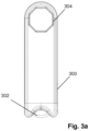
- FIG 3a shows an exemplary mobile electronic device 300, which may be used as a device 102 in Figure 1 .
- the exemplary mobile electronic device 300 may comprise the features of the mobile electronic 102 shown in Figure 2 .
- the exemplary mobile electronic device 300 may be used as a key fob and comprises a retaining feature 302, in this case a bar that may be secured to a clip or ring, for attaching the device 300 to a key ring.
- the exemplary mobile electronic device 300 may comprise a locating feature 304 configured to ensure correct positioning of the antenna of the tyre pressure sensor module 100 relative to the transmitter 200 of the mobile electronic device 300.
- the locating feature 304 may be a mechanical feature (such as a recess or a protrusion) or the locating feature may be electronic (for example, an electronic arrangement configured to produce an electronic indication of correct positioning, such as a vibration or an audio indication). In some arrangements, the locating feature may comprise both a mechanical feature and an electronic feature.
- the mobile electronic device 300 may take any shape and in the case of the example of Figure 3a is broadly rectangular with a curved end formed by a semi-circle.
- the curved end of the device 300 comprises the locating feature 304.
- the locating feature is configured to cooperate with the tyre pressure sensor module 100 to locate the tyre pressure sensor module 100 in a predetermined orientation and/or range of the transmitter 200 and/or receiver 202 of the mobile electronic device 300.
- the locating feature 304 comprises a keyed feature (e.g. an octagon, hexagon, triangle or circle) that is configured to receive, at least partially, a correspondingly shaped tyre pressure sensor module 100.
- the locating feature 304 comprises an octagonal recess that is configured to receive an octagonal tyre pressure sensor module 100.
- this may mean that the antenna of the tyre pressure sensor module 100 is within 4 cm of the transmitter 200 and/or receiver 202 of the mobile electronic device 300.
- the indication may be the haptic indication that the user may feel when the tyre pressure sensor module 100 locates within the recess of the locating feature 304.
- alternative and/or additional means for providing an indication to the user may be utilised.
- magnetic force may be used. That is, at least one magnet may be located in one or both of the mobile electronic device 300 and the tyre pressure sensor module 100 to align the two. The magnetic force generated by the at least one magnet may provide a haptic indication to the user that the tyre pressure sensor module is correctly located.
- the locating feature comprises an indicator unit 212.
- the indicator unit 212 may be configured to detect when a telecommunications signal is received by the mobile electronic device 300 from the tyre pressure sensor module 100 and then to produce an indication to the user, such as a visual, audio or haptic indication.
- the haptic indication may be a vibration of the device 300.
- the telecommunications signal may comprise a tyre pressure reading such that the indication unit indicates to the user that the tyre pressure reading has been received by the mobile electronic device 300. This indicates to the user when they can bring the mobile electronic device out of alignment with the tyre pressure sensor module, if the position of the tyre pressure sensor module 100 is such that the user cannot see the mobile electronic device 300 is not visible to the user.
- the indicator unit 212 may be utilised in addition to the keyed feature as described above. Alternatively, the indicator unit may be used in isolation from the keyed feature, such that the visual, audio or haptic indication generated by the indicator unit provides an indication to the user of correct alignment.
- Figure 3b shows a flow diagram for obtaining a tyre pressure reading using a mobile electronic device 102 as disclosed herein.
- the method comprises a user of a mobile electronic device 102 placing the mobile electronic device 102 in proximity to a tyre pressure sensor module 100.
- the mobile electronic device 102 is configured to provide 350 an indication to the user that the transmitter 200 and/or receiver 202 of the mobile electronic device 102 are located within 4 cm or less of the tyre pressure sensor module 100.
- the transmitter 200 then transmits 352 a telecommunications signal to the tyre pressure sensor module 100.
- the telecommunications signal is received by the tyre pressure sensor module 100 and instructs the tyre pressure sensor module 100 to transmit a tyre pressure reading.
- the receiver 202 receives 354 a telecommunications signal from the tyre pressure sensor module 100, the received telecommunications signal comprising the tyre pressure reading.
- the indicator unit 212 may provide an indication to the user to confirm that the telecommunications signal has been received by the receiver 202. This indication may confirm that the tyre pressure reading has been received by the receiver 202. The indication may occur after the initial indication to the user that the transmitter 200 and/or receiver 202 of the mobile electronic device 102 are located within 4 cm or less of the tyre pressure sensor module 100.
- a locating feature 400 is shown that may adhered or otherwise fixed to an existing mobile electronic device 102.
- the locating feature is a sticker 400 with a raised or embossed design thereon to create a locating feature 404.
- the locating feature 404 may the same or similar to the locating feature 304 described already in respect of Figure 3 .
- the locating feature may be moulded and adhered to the mobile electronic device using a suitable adhesive.
- the sticker 400 comprises a raised or embossed feature having sidewalls 406 defining a recess 408.
- the recess 408 is configured to receive, at least partially, the profile of a tyre pressure sensor module 100.
- the sidewalls 406 define a circular recess 408, any other shaped recess (e.g. an octagon, hexagon, triangle) may be used to correspond to the profile of the tyre pressure sensor module 100. This may produce a keyed recess only receiving the tyre pressure sensor module in a limited number of orientations.
- the sticker 400 may have an adhesive backing (not shown) for adhering the sticker 400 to an existing mobile electronic device 102.
- Figure 5 shows an exemplary sticker 400 adhered to a smart phone 102, although it could be adhered to any other type of mobile electronic device.
- the sticker 400 is positioned such that when a tyre pressure sensor module 100 is correctly located with respect to the sticker 400, e.g. at least partially received in the recess 408, then the tyre pressure sensor module 100 is within range of the transmitter 200 and/or receiver 202 of the smart phone 102.
- the sticker 400 is shown centrally located on the smart phone 102, although other locations may be used dependent on the structure of the smart phone 102.
- Figure 6 shows an alternative arrangement in which a locating feature 600 that is the same or similar to other locating features described herein is positioned on a cover 602 for a mobile electronic device, in this case a smart phone 102.
- the locating feature 600 is positioned on the cover 600 such that when a tyre pressure sensor module 100 is correctly located with respect to the locating feature 600, e.g. at least partially received in the recess, and the cover is fitted to the mobile electronic device 102 then the tyre pressure sensor module 100 is within range of the transmitter 200 and/or receiver 202 of the mobile electronic device 102.
- the locating feature 600 is shown centrally located on cover 602, although other locations may be used dependent on the structure of the mobile electronic device 102 to which the cover is to be fitted.
- the locating feature 600 may be an aperture in the phone case, the aperture positioned such that when a tyre pressure sensor module 100 is received within the aperture, the tyre pressure sensor module 100 is within range of the transmitter 200 and/or receiver 202 of the mobile electronic device 102.
- the locating feature may be a recess in the case that does not have raised or embossed sidewalls. That is, the upper edge of the recess may be flush with the outer surface of the case.
- a user of the tyre pressure gauge system may walk around the vehicle with the mobile electronic device 102.
- the user may hold the mobile electronic device 102 in close proximity to the tyre pressure sensor module 100 (this may comprise using a locating feature as described herein).
- the mobile electronic device 102 may transmit a signal that provides power to the tyre pressure sensor module 100.
- the power may be sufficient to enable determination of the pressure of air in the pneumatic tyre 106 of the vehicle.
- the determined pressure may be transmitted to the mobile electronic device 102 for display to the user.
- the mobile electronic device may be configured to transmit a short range telecommunications signal to the tyre pressure module.
- the short range telecommunications signal may allow an antenna of the tyre pressure sensor unit to obtain sufficient electrical power to allow measurement of a pressure of a fluid within the pneumatic tyre and transmission of data indicative of the measured pressure to the mobile electronic device.
- exemplary tyre pressure sensor units may be battery-less, allowing for production of a sensor unit of reduced size, weight, complexity and power consumption.
- Additional tyre pressure sensor module size and weight reductions may be achieved by reducing the size of the antenna of the tyre pressure module. Traditionally, this would not be desirable, since reducing the antenna size may affect the transmission range. It may also mean that the mobile electronic device needs to be placed in closer proximity to and more accurately located with respect to the pressure sensor unit to allow a pressure reading to be taken, which may be difficult for the user of the mobile electronics device, particularly if the tyre pressure sensor module is not visible.
- a reduced transmission range allows separate tyre pressures to be read without the need for the mobile electronic device to identify and distinguish the pressure sensor module it wishes to read from others on the vehicle. Because only pressure sensor modules within a small range can be read, it is clear which sensor module is providing a particular pressure reading.
- the tyre pressure sensor module is now described in greater detail.
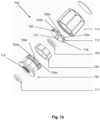
- the tyre pressure sensor module 700 comprises a housing split into a forward portion 708, a rear portion 710 and sensor electronics 712 comprising a pressure sensor 714.
- the forward portion 708 comprises an internal thread 716 for screwing onto a threaded portion of the valve 104 of a pneumatic tyre 106.
- the valve 104 may be of a Schrader valve structure.
- the forward portion 708 may also comprise a valve actuation member (not shown) configured to open the tyre valve on attachment of the tyre pressure sensor module 700 thereto.
- a valve actuation member (not shown) configured to open the tyre valve on attachment of the tyre pressure sensor module 700 thereto.
- the actuation member protrudes into the valve structure to depress a valve stem and open the valve.
- the forward portion 708 is configured to form an airtight seal with the tyre valve by way of interaction between the internal thread 716 and the threaded portion of the valve. In this way, air is only required to be released from the tyre 102 and into the volume surrounding the valve structure on fitting the tyre pressure sensor module.
- Exemplary tyre pressure sensor modules 700 may also comprise a valve plug 717 configured to provide an airtight seal with the tyre valve 104.
- the forward portion 708 may also comprise a fluid communication path (not shown).
- the fluid communication path may extend from the internal thread 716 to the sensor electronics 712.
- the fluid communication path is configured to allow air (or other fluid) from within the pneumatic tyre 106 to pass from the open valve 104 to the pressure sensor 714.
- the sensor electronics 712 may be mounted on a printed circuit board (PCB) 718.
- the sensor electronics 712 may comprise the pressure sensor 714, an antenna and a microprocessor.
- the sensor electronics may consist of the pressure sensor 714, the antenna and the microprocessor, which may include a receiver and a transmitter.
- sensor electronics encompasses electronic apparatus having a defined electronic operation within the context of the device itself, for example the pressure sensor, receiver, transmitter and antenna.
- the term electronic component as used in that context does not encompass elemental components such as wires, PCB track, resistors, capacitors etc.
- the antenna may be a loop antenna.
- the antenna may have a diameter of substantially 10 mm, a width of substantially 0.15 mm and comprise 14 turns.
- the antenna may additionally have a thickness of substantially 0.35 mm and a track width of substantially 0.15 mm
- Exemplary tyre pressure sensor modules may be battery-less.
- the antenna may be configured to receive a short range telecommunications signal and draw power therefrom such that the pressure sensor 714 can take a pressure reading.
- Exemplary antennas may be configured to draw sufficient power from the telecommunications signal over a distance of up to 4cm.
- the telecommunications signal may be an NFC signal.
- the PCB 718 may comprise to a locating member 720 configured to interact with a corresponding locating feature of the forward portion 708 to secure the PCB 718 thereto.
- the locating member 720 comprises locating lugs 722a-n configured to engage with corresponding locating recesses 724an on the forward portion 708.
- the forward portion may comprise locating lugs configured to engage with locating recesses on the PCB 718.
- Alternative mounting means may be utilised to secure the PCB 718 to the forward portion 708.
- the locating member 720 may be configured to ensure that the PCB 718 is mounted to the forward portion 708 such that the pressure sensor 714 is positioned to enable pressure readings to be taken.
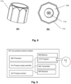
- the rear portion 710 is of substantially cup-like shape and is configured to surround the sensor electronics and body of the forward portion 708 when secured thereto. As shown in Figures 8a and 8b , which show an isometric view and a bottom view of the tyre pressure sensor unit 700 respectively, the rear portion 710 surrounds substantially all of the body of the forward portion 708 such that only the internal thread 716 and underside of the forward portion 708 are left exposed.
- a housing seal 726 may be secured between the forward portion 708 and the rear portion 710 to provide a watertight seal to prevent water ingress to the sensor electronics 712.
- the watertight seal may comprise an O-ring configured to surround the PCB 718.
- the tyre pressure sensor module may not comprise a housing seal.
- the forward portion 708 may be secured to the rear portion 710 with an adhesive or ultrasonic weld to form a watertight seal.
- the tyre pressure sensor module 700 may further comprise a pressure sensor seal 728 configured to surround the pressure sensor 714 and provide further protection against water ingress.
- Exemplary tyre pressure sensor modules 100, 700 may have a substantially circular, hexagonal, square or octagonal profile when viewed from the top. Further, exemplary tyre pressure sensor modules 100, 700 may be configured to interact with a locating feature of a mobile electronic device to provide an indication of when the tyre pressure sensor module 100, 700 is aligned with a transmitter and/or receiver of the mobile electronic device to allow telecommunication therebetween. In some examples, tyre pressure sensor modules 100, 700 may be configured to be at least partially received within a recess formed by the locating feature and may have a profile corresponding to a shape of the recess.
- Exemplary tyre pressure sensor modules 100, 700 may have a diameter of substantially 18mm. Further, the length from a forward end of the forward portion 708 to the rearward end of the rear portion 106 may be substantially 15mm. The weight of exemplary sensor units 102 may be 5 grams or less or may be 4 grams or less.
- Figure 7c shows an alternative tyre pressure sensor module 730.
- Some of the features of the tyre pressure sensor module 730 of Figure 7c are similar to those described above in relation to the tyre pressure sensor module 700 of Figures 7a and b. As such, a description of these features is not given again here and corresponding reference numerals are used to identify them in Figure 7c .
- the tyre pressure sensor module 730 comprises a housing split into a forward portion 738, a rear portion 740, and sensor electronics 712 comprising a pressure sensor 714.
- the sensor electronics 712 may be mounted on a printed circuit board (PCB) 748.
- PCB printed circuit board
- the tyre pressure sensor module 730 may comprise a protruded portion 731.
- the rear portion 740 may comprise the protruded portion 731.
- the protruded portion 731 may be configured to receive an antenna for communicating with a mobile electronic device, as described below.
- Exemplary tyre pressure sensor modules 730 may comprise a plurality of PCBs.
- the exemplary tyre pressure sensor module 730 comprises two PCBs 748a, 748b, however the skilled person will appreciate that any number of PCBs may be utilised.
- the PCBs 748a, 748b may be stacked.
- Each PCB 748a, 748b may comprise sensor electronics.
- the exemplary tyre pressure sensor module 730 may further comprise locating features configured to facilitate the correct placement of the PCB(s) within the housing.
- at least one of the PCBs 748a,b may comprise a locating recess 750 configured to engage with corresponding locating member 752 on the housing (for example, the forward portion 738 of the housing).
- the PCB 748b comprises three locating recesses 750a-c and the housing comprises three corresponding locating members 752a-c, however the skilled person will appreciate that any number of locating recesses and locating members may be utilised.
- At least one locating member 752a-c may be configured to hold the PCBs 748a, 748b at a desired height within the housing.
- At least one locating member 752a-c may comprise a lug 756 configured to be received within a corresponding recess 754 of the PCB 748a.
- the locating member 752 may further comprise an engagement surface 758 configured to abut a surface of the PCB 748a when the lug 756 is received within the recess 754.
- the locating member may comprise an engagement surface (without the lug).
- Exemplary tyre pressure sensor modules may comprise a fastener 760 configured to secure the PCB(s) to the housing.
- the fastener 760 may be configured to secure the PCB(s) to the forward portion 738 of the housing.
- the fastener may be a screw, a bolt, a nail or any other suitable type of fastener.
- the exemplary tyre pressure sensor module 730 shown in Figure 7c comprises three fasteners configured to secure the PCB 748 to the forward portion 738, however the skilled person will appreciate that substantially any number of fasteners may be used.
- the PCB may comprise a plurality of holes 762 for receiving the fasteners 736.
- the forward portion 738 may comprise a plurality of fastening ports 764 configured to engage the fasteners 760, to secure the PCB(s) 748 to the forward portion 738.
- FIG 9 shows a schematic representation of a tyre pressure sensor module 900, which may be the tyre pressure sensor module of Figures 7a-c , 8a or 8b .
- the tyre pressure sensor module 900 comprises a transmitter 902 and a receiver 904.
- the receiver 904 may comprise an antenna as discussed above, configured to receive a short range RF signal and configured to draw electrical power therefrom.
- the transmitter 902 and receiver 904 may be in data communication with other entities in a tyre pressure gauge system, such as a mobile electronic device 102 and are configured to transmit and receive data accordingly.
- the transmitter 902 and receiver 904 may be configured to transmit and receive data using a short range radio frequency (RF) signal, such as an NFC signal, as discussed above.
- RF radio frequency
- the tyre pressure sensor module further comprises a memory 906 and a processor 908.
- the memory 906 may comprise a non-volatile memory and/or a volatile memory.
- the memory 906 may have a computer program 910 stored therein.
- the computer program 910 may be configured to undertake the methods disclosed herein.
- the computer program 910 may be loaded in the memory 906 from a non-transitory computer readable media 912, on which the computer program is stored.
- the tyre pressure sensor module 700 further comprises a pressure sensor 916 configured to determine pressure within a tyre when fitted to a valve thereof.
- the processor 908 may be configured to undertake the function of a pressure data controller 914 as set out herein.
- Each of the transmitter 902 and receiver 904, memory 906, processor 908, pressure data controller 914, pressure sensor 916 may be in data/electrical communication with the other features 902, 904, 906, 908, 910, 914, 916 of the tyre pressure sensor module 700.
- the tyre pressure sensor module 700 can be implemented as a combination of computer hardware and software.
- pressure data controller 914 may be implemented as software configured to run on the processor 908.
- the memory 906 stores the various programs/executable files that are implemented by a processor 908, and also provides a storage unit for any required data.
- the programs/executable files stored in the memory 906, and implemented by the processor 908, can include the pressure data controller 914 but are not limited to such.
- exemplary tyre pressure sensor modules are battery-less. This, combined with the use of a smaller antenna allows for the reduced size and weight of exemplary tyre pressure sensor modules.
- the use of a smaller antenna also provides for a less complex system by reducing the distance over which the antenna of the tyre pressure sensor module can obtain sufficient power to enable tyre pressure to be determined.
- tyre pressure sensor modules within a small range can be read, it is clear which sensor module is providing a particular pressure reading. This means that there is no requirement for identification of individual tyre pressure sensor modules when transmitting pressure data.
- exemplary tyre pressure sensors may be configured to transmit identification data.
- the identification data may be unique to the tyre pressure sensor module.
- the identification data may be transmitted by the tyre pressure sensor module when the pressure data is transmitted. That is, the identification data may be transmitted in response to a request for data from the mobile electronic device.
- the identification data may associate the pressure data with a particular tyre pressure sensor module (and as such, the corresponding wheel of the vehicle to which the tyre pressure sensor module is coupled).
- Such identification data may comprise a number, letter, or colour.
- the identification data may be used when storing tyre pressure data, as described in more detail below.
- the identification data provides an indication of which tyre pressure sensor modules is associated with which tyre pressure reading(s). This may be useful when viewing a list of many readings from different vehicles and/or tyres, as each reading may be associated with a particular vehicle and/or tyre.
- Exemplary tyre pressure sensor modules comprise only sensors for measuring tyre pressure. That is, exemplary tyre pressure sensor modules may not comprise any sensors for monitoring a parameter of the tyre and/or wheel other than the pressure sensor. Specifically, the tyre pressure sensor module may not including a temperature sensor and/or a motion sensor. Again, this provides a much lower power, smaller, lighter and lower cost sensor unit than, for example, a TPMS. It is noted that this is against the direction of innovation in the art, which is towards greater functionality and a greater numbers of features.
- reducing the diameter (and therefore surface area) of the antenna significantly reduces the inductance and therefore the transmission range (both laterally and vertically).
- a reduction in the number of turns of the antenna significantly reduces the inductance and therefore the transmission range.
- turns as used in the context of antennas encompasses concentric, spiralled revolutions of a material forming the antenna. This will be understood by the skilled person.
- the tyre pressure sensor module may be mounted to a tyre in a position such that it is not visible to the user. As such, the user may be unable to position the mobile electronics device relative to the tyre pressure sensor in such a way to allow a pressure reading to be taken and transmitted.
- the mobile electronic device 102 is placed in close proximity to a tyre pressure sensor module 700.
- close proximity may encompass distances up to 4 cm, up to 3 cm, up to 2 cm or up to 1 cm.
- close proximity is a distance sufficiently close to allow an NFC (or other short range telecommunications signals such as an RF signal, including RFID) transmission from the mobile electronic device 102 to be detected by the antenna of the receiver 904 of the tyre pressure sensor module 700 using one of the transmission means disclosed herein.
- the transmitter 202 of the mobile electronic device 102 transmits a short range telecommunications signal, such as NFC or RFID, to the tyre pressure sensor module.
- the short range telecommunications signal may be a request for a tyre pressure measurement.
- the transmission may be undertaken using NFC transmission techniques.
- the short range telecommunications signal may therefore have a range of up to 4 cm, up to 3 cm, up to 2 cm or up to 1 cm.
- the short range telecommunications signal transmission may be in response to a user input, for example a user pressing a button on the mobile electronic device 102.
- the transmitter 202 of the mobile electronic device 102 may use a transmission frequency of 13.56 MHz.
- the mobile electronic device 102 and the tyre pressure module 100 communicate via inductive coupling when the antenna of the tyre pressure sensor module 700 is within range of the transmitter 202 and/or receiver 200 of the mobile electronic device 102.
- the receiver 904 of the tyre pressure sensor module 700 detects the short range telecommunications signal transmission from the mobile electronic device 102.
- the telecommunications signal is received at the antenna, which is configured to induce a voltage in the tyre pressure sensor module sufficient to power the tyre pressure sensor module to take a measurement of a pressure of a fluid within the pneumatic tyre and transmission of data indicative of the measured pressure to the mobile electronic device 102.
- the pressure sensor 714 On receipt of the short range telecommunications signal, the pressure sensor 714 therefore determines the pressure of the air in the tyre of the respective wheel of the vehicle.
- the pressure data controller 914 controls the transmitter 902 to transmit pressure data indicative of the determined tyre pressure to the mobile electronic device 102.
- the transmitter may transmit the data via a short range telecommunications signal having a range of less than 4 cm, such as an NFC RF signal or an RFID RF signal. In other arrangements, a different telecommunications protocol may be used to transmit the pressure data.
- the tyre pressure sensor module 700 may be further configured to transmit identification data in response to the short range telecommunications signal received from the mobile electronic device 102.
- the identification data may associate the pressure data with a corresponding tyre pressure sensor module (and therefore the corresponding wheel of the vehicle to which the tyre pressure sensor module is coupled).
- the identification data may be transmitted via a short range telecommunications signal having a range of less than 4 cm, such as an NFC RF signal or an RFID RF signal.
- a different telecommunications protocol may be used to transmit the identification data.
- the receiver 200 of the mobile electronic device 300 receives the tyre pressure data and may display the tyre pressure to the user. In exemplary methods, the receiver may also receive the identification data and display this to the user in addition to the tyre pressure. The user then moves to the next tyre/wheel of the vehicle and repeats the process to determine the pressure at each tyre pressure sensor module.
- the tyre pressure data received by the mobile electronic device 300 may be compared to a desired tyre pressure in order to determine whether the tyre is at a safe pressure or whether the tyre is in need of inflation.
- a warning may be displayed to the user if the measured tyre pressure is less than a threshold.
- the threshold may be defined as a percentage of the desired tyre pressure.
- Exemplary mobile electronic devices may comprise a user interface through which the user can programme and/or control the mobile electronic device 300.
- the user may input into the mobile electronic device, via the user interface, a desired tyre pressure for a particular tyre of a vehicle.
- the user interface may comprise a display screen configured to display data to the user.
- the display screen may be a touchscreen configured to display data to the user and to allow a user to make user inputs to the screen to programme and/or control the mobile electronic device 300.
- Exemplary mobile electronic devices may be configured to transmit data confirming whether the pressure of the tyre has been checked to a server connected to a network.
- the server may be configured to store the data confirming that the pressure of the tyre has been checked.
- the server may be a virtual server, such as a Cloud server.
- a signal confirming a pressure check has taken place may be transmitted to the server by the transmitter 202 of the mobile electronic device.
- the transmitter 202 of the mobile electronic device 102 may be configured to transmit the received tyre pressure data and/or the identification data to the server.
- the tyre pressure data and/or identification data may be timestamped to indicate the time at which the pressure measurement was taken or the time at which the measured pressure/identification data was received by the mobile electronic device.
- the server may be configured to store the measured pressure and/or identification data received from the mobile electronic device.
- Transmitting the tyre pressure data and/or identification data to the server and storing the data thereon allows a third party, for example, to track whether/when pressure measurements have been taken. This may allow, for example, the monitoring of multiple drivers to determine whether they have checked the tyre pressures of their vehicle before beginning a journey (or at predetermined checkpoints). In arrangements in which the pressure data is transmitted to the server, this also allows monitoring of whether drivers have started their journey despite the tyre not being at a safe pressure.
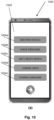
- FIG 10 shows an exemplary mobile electronic device 1000, which is a smartphone.
- the mobile electronic device 1000 comprises a touchscreen 1002, which displays selectable icons 1004a-n.
- the user may make user inputs to navigate the user interface via the selectable icons 1004a-n.
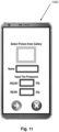
- the user may select one of the icons 1004a-n to navigate to the screen as shown in Figure 10b, which allows the user to make a user input to define a desired pressure value that would indicate that a tyre is of a safe pressure.
- a desired front tyre pressure and a desired back tyre pressure may be separately definable.
- the measured tyre pressure may be compared to a threshold to determine whether the tyre is safe or underinflated. If the desired front pressure and the desired back pressure are of different values, once the tyre pressure reading is received by the mobile electronic device 1000 from the tyre pressure sensor module 100, the user may receive a prompt to indicate whether the tyre that the pressure reading is associated with is a front or back tyre.
- the user may be alerted if the measured tyre pressure is lower than the threshold.
- the alert could be visual, audio or haptic.
- a warning may be displayed to the user if the measured tyre pressure is lower than the threshold. This could be displayed to the user in a trafficlight fashion, with green indicating that the tyre is safe, amber indicating that the tyre needs to be inflated and red indicating that the tyre is unsafe.
- the threshold may be user-configurable or alternatively, pre-programmed into the mobile electronic device 1000.
- the threshold may be defined as a percentage of the desired pressure value.
- the threshold may be defined as approximately 12% of the desired tyre pressure, such that a measured tyre pressure of less than 12% of the desired tyre pressure value indicates that the tyre needs to be inflated.
- a second threshold may indicate that the tyre is unsafe.
- a second threshold may be set at approximately 18% of the desired tyre pressure, such that a measured tyre pressure of less than 18% of the desired tyre pressure value indicates that the tyre is unsafe.
- the user may create a plurality of vehicle profiles and input different desired tyre pressure values and thresholds associated with tyres of a particular vehicle. In this way, a single mobile electronic device may be utilised with a number of different vehicles and tyre pressure sensor modules.
- the user interface may further allow the user to select the units (psi or bar) that the measured pressure reading should be displayed in and/or the language.
- a computer program may be configured to provide at least part of any of the above described methods.
- the computer program may be provided on a computer readable medium.
- the computer program may be a computer program product.
- the product may comprise a non-transitory computer usable storage medium.
- the computer program product may have computer-readable program code embodied in the medium configured to perform the method.
- the computer program product may be configured to cause at least one processor to perform some or all of the method.
- a sensor module may be provided which comprises sensors for monitoring other environmental parameters.
- Such parameters may include pressure, temperature, motion, humidity, and/or light intensity.
- sensor modules may be placed around a building (or a room of a building) for monitoring these parameters.
- a mobile electronic device substantially similar to those described herein may be provided which may receive data in the manner described above, from the sensor module and display this data to the user.
- tyre pressure sensor modules 700, 730 may be structurally different from the tyre pressure sensor modules 700, 730.
- the tyre pressure sensor modules 700, 730 are configured to engage a Schrader valve. It will be appreciated that in alternative applications, this may not be necessary.
- an environmental sensor module comprising an antenna configured to detect a short range telecommunications signal from a mobile electronic device over a distance of up to 4 cm.
- the antenna may be configured to obtain, from the short range telecommunications signal through induction, electrical power sufficient to allow measurement of one or more environmental parameters and transmission of data indicative of the one or more measured environmental parameters to the mobile electronic device.
- the environmental sensor module may further comprise a receiver configured to receive the short range telecommunications signal comprising the a request to obtain one or more environmental parameter readings.
- the environmental sensor module may further comprise an environmental parameter sensor configured to measure one or more environmental parameters in response to the request.
- the environmental sensor module may further comprise a transmitter configured to transmit data indicative of the measured environmental parameter to the mobile electronic device using a short range telecommunications signal over a distance of up to 4 cm.
- the mobile electronic device may the mobile electronic device 102 described above.
- the environmental parameters may comprise pressure, temperature, motion, humidity, and/or light intensity.
- the environmental parameter sensor may comprise a pressure sensor, a temperature sensor, a motion sensor, a humidity sensor and/or a light intensity sensor.
- These computer program instructions may be provided to a processor circuit of a general purpose computer circuit, special purpose computer circuit, and/or other programmable data processing circuit to produce a machine, such that the instructions, which execute via the processor of the computer and/or other programmable data processing apparatus, transform and control transistors, values stored in memory locations, and other hardware components within such circuitry to implement the functions/acts specified in the block diagrams and/or flowchart block or blocks, and thereby create means (functionality) and/or structure for implementing the functions/acts specified in the block diagrams and/or flowchart block(s).
- Computer program instructions may also be stored in a computer-readable medium that can direct a computer or other programmable data processing apparatus to function in a particular manner, such that the instructions stored in the computer-readable medium produce an article of manufacture including instructions which implement the functions/acts specified in the block diagrams and/or flowchart block or blocks.
- a tangible, non-transitory computer-readable medium may include an electronic, magnetic, optical, electromagnetic, or semiconductor data storage system, apparatus, or device. More specific examples of the computer-readable medium would include the following: a portable computer diskette, a random access memory (RAM) circuit, a read-only memory (ROM) circuit, an erasable programmable read-only memory (EPROM or Flash memory) circuit, a portable compact disc read-only memory (CD-ROM), and a portable digital video disc read-only memory (DVD/Blu-ray).
- RAM random access memory
- ROM read-only memory
- EPROM or Flash memory erasable programmable read-only memory
- CD-ROM compact disc read-only memory
- DVD/Blu-ray portable digital video disc read-only memory
- the computer program instructions may also be loaded onto a computer and/or other programmable data processing apparatus to cause a series of operational steps to be performed on the computer and/or other programmable apparatus to produce a computer-implemented process such that the instructions which execute on the computer or other programmable apparatus provide steps for implementing the functions/acts specified in the block diagrams and/or flowchart block or blocks.
- the invention may be embodied in hardware and/or in software (including firmware, resident software, micro-code, etc.) that runs on a processor, which may collectively be referred to as "circuitry," "a module” or variants thereof.
Landscapes
- Engineering & Computer Science (AREA)
- Mechanical Engineering (AREA)
- Computer Networks & Wireless Communication (AREA)
- Measuring Fluid Pressure (AREA)
Claims (15)
- Kit de parties comprenant :
un module de capteur de pression de pneu (100, 700, 730) destiné à être adapté sur une valve (104) d'un pneumatique (106), le module de capteur de pression de pneu (100, 700, 730) comprenant :une antenne configurée pour détecter un signal de télécommunication de portée courte en provenance d'un dispositif électronique mobile (102, 300) sur une distance allant jusqu'à 4 cm, l'antenne étant en outre configurée pour obtenir, à partir du signal de télécommunication de portée courte, par induction, de la puissance électrique suffisante pour permettre la mesure d'une pression d'un fluide à l'intérieur du pneumatique (106) et la transmission de données indicatives de la pression mesurée sur le dispositif électronique mobile (102, 300) ;un récepteur (904) configuré pour recevoir le signal de télécommunication de portée courte, lequel comprend des instructions pour obtenir une lecture de pression ;un capteur de pression (916) configuré pour mesurer la pression du fluide à l'intérieur du pneumatique (106) ; etun émetteur (902) configuré pour émettre des données indicatives de la pression mesurée sur le dispositif électronique mobile (102, 300) en utilisant un signal de télécommunication de portée courte sur une distance allant jusqu'à 4 cm ; etune caractéristique de localisation (400) destinée à être fixée sur un carter d'un dispositif électronique mobile (102, 300) et configurée pour fournir une indication à un utilisateur du dispositif électronique mobile (102, 300) lorsqu'un émetteur et/ou un récepteur du dispositif électronique mobile (102, 300) sont/est localisé(s) à l'intérieur de 4 cm ou moins du module de capteur de pression de pneu (100, 700, 730). - Kit de parties selon la revendication 1, dans lequel la caractéristique de localisation (400) comprend un revêtement adhésif sur son côté inférieur destiné à adhérer sur le carter du dispositif électronique mobile (102, 300).
- Kit de parties selon la revendication 1 ou 2, dans lequel l'antenne est une antenne en boucle présentant un diamètre de sensiblement 10 mm, une largeur de sensiblement 0,15 mm et comportant sensiblement 14 spires.
- Kit de parties selon l'une quelconque des revendications précédentes, dans lequel le module de capteur de pression de pneu (100, 700, 730) ne comprend pas de capteurs pour surveiller un paramètre du pneumatique (106) et/ou de la roue autres que le capteur de pression (916) et en option spécifiquement, n'incluant pas un capteur de température et/ou un capteur de mouvement.
- Kit de parties selon l'une quelconque des revendications précédentes, dans lequel au moins une partie du module de capteur de pression de pneu (100, 700, 730) est configurée pour être reçue à l'intérieur de la caractéristique de localisation (400).
- Kit de parties selon la revendication 5, dans lequel le module de capteur de pression de pneu (100, 700, 730) comprend un évidement claveté configuré pour être reçu à l'intérieur d'une partie clavetée en correspondance (408) de la caractéristique de localisation.
- Kit de parties selon l'une quelconque des revendications précédentes, comprenant en outre le fait que le dispositif électronique mobile (102, 300) comprend :un émetteur (202) configuré pour émettre un signal de télécommunication sur le module de capteur de pression de pneu (100, 700, 730) sur une distance allant jusqu'à 4 cm, dans lequel le signal de télécommunication est configuré pour être reçu par le module de capteur de pression de pneu (100, 700, 730) et pour demander au module de capteur de pression de pneu (100, 700, 730) d'émettre une lecture de pression de pneu ; etun récepteur (200) configuré pour recevoir un signal de télécommunication en provenance du module de capteur de pression de pneu (100, 700, 730) sur une distance allant jusqu'à 4 cm, le signal de télécommunication reçu comprenant la lecture de pression de pneu.
- Kit de parties selon la revendication 7, dans lequel l'émetteur (902) du module de capteur de pression de pneu (100, 700, 730) est en outre configuré pour émettre des données d'identification sur le dispositif électronique mobile (102, 300) et en option, dans lequel les données d'identification associent les données indicatives de la pression mesurée au module de capteur de pression de pneu (100, 700, 730) .
- Système de manomètre pour pneu comprenant :un dispositif électronique mobile (102, 300) et un module de capteur de pression de pneu (100, 700, 730), le module de capteur de pression de pneu (100, 700, 730) étant destiné à être adapté sur une valve (104) d'un pneumatique (106), dans lequel le dispositif électronique mobile (102, 300) comprend un émetteur (202) configuré pour émettre un signal de télécommunication comprenant une demande concernant une lecture de pression de pneu sur le module de capteur de pression de pneu (100, 700, 730), sur une distance allant jusqu'à 4 cm ;dans lequel le module de capteur de pression de pneu (100, 700, 730) comprend une antenne configurée pour recevoir le signal de télécommunication et en obtenir, par induction, de la puissance électrique suffisante pour permettre la mesure d'une pression d'un fluide à l'intérieur du pneumatique et la transmission de données indicatives de la pression mesurée sur le dispositif électronique mobile (102, 300), le module de capteur de pression de pneu comprenant en outre un capteur de pression (916) configuré pour mesurer la pression de pneu et un émetteur (902) configuré pour émettre des données indicatives de la pression mesurée sur le dispositif électronique mobile (102, 300) ;dans lequel le dispositif électronique mobile (102, 300) comprend en outre un récepteur (200) configuré pour recevoir les données émises indicatives de la lecture de pression de pneu sur une distance allant jusqu'à 4 cm, et une caractéristique de localisation (304) configurée pour fournir une indication à un utilisateur du dispositif électronique mobile (102, 300) lorsque l'émetteur (202) et/ou le récepteur (200) du dispositif électronique mobile (102, 300) sont/est localisé(s) à l'intérieur de 4 cm ou moins du module de capteur de pression de pneu (100, 700, 730).
- Système de manomètre pour pneu selon la revendication 9, dans lequel la caractéristique de localisation (304) est configurée pour recevoir au moins une partie du module de capteur de pression de pneu (100, 700, 730).
- Système de manomètre pour pneu selon la revendication 9 ou 10, dans lequel la caractéristique de localisation (304) comprend un évidement claveté à l'intérieur duquel une partie clavetée en correspondance du module de capteur de pression de pneu (100, 700, 730) peut être reçue.
- Système de manomètre pour pneu selon l'une quelconque des revendications 9 à 11, dans lequel la caractéristique de localisation (304) comprend en outre une unité indicatrice (212) configurée pour fournir à l'utilisateur une ou plusieurs indications audio, visuelles ou haptiques.
- Système de manomètre pour pneu selon la revendication 12, dans lequel le récepteur (200) est configuré pour, suite à la réception du signal de télécommunication en provenance du module de capteur de pression de pneu (100, 700, 730), commander l'unité indicatrice (212) pour qu'elle fournisse l'indication à l'utilisateur.
- Procédé pour obtenir une lecture de pression de pneu à partir d'un module de capteur de pression de pneu (100, 700, 730) qui est adapté sur une valve (104) d'un pneumatique (106), le procédé comprenant :la fourniture, par une caractéristique de localisation (304, 400) fixée sur un dispositif électronique mobile (102, 300) ou formant une partie de ce même dispositif, d'une indication à un utilisateur du dispositif électronique mobile (102, 300), lorsqu'un émetteur (202) et un récepteur (200) du dispositif électronique mobile (102, 300) sont localisés à l'intérieur de 4 cm ou moins du module de capteur de pression de pneu (100, 700, 730) ;l'émission, par un émetteur (202) du dispositif électronique mobile (102, 300), d'un signal de télécommunication sur le module de capteur de pression de pneu (100, 700, 730) sur une distance allant jusqu'à 4 cm une fois que l'indication a été reçue, dans lequel le signal de télécommunication est reçu par le module de capteur de pression de pneu (100, 700, 730) et il donne au module de capteur de pression de pneu (100, 700, 730) l'instruction d'émettre une lecture de pression de pneu ; etla réception, par un récepteur (200) du dispositif électronique mobile (102, 300), d'un signal de télécommunication en provenance du module de capteur de pression de pneu (100, 700, 730) sur une distance allant jusqu'à 4 cm, le signal de télécommunication reçu comprenant la lecture de pression de pneu.
- Procédé selon la revendication 14, comprenant en outre :la détection, par une antenne du module de capteur de pression de pneu (100, 700, 730), du signal de télécommunication en provenance du dispositif électronique mobile (102, 300) comprenant des instructions pour obtenir une lecture de pression ;l'obtention, par l'antenne et à partir du signal de télécommunication, par induction, de la puissance électrique suffisante pour permettre la mesure d'une pression d'un fluide à l'intérieur du pneumatique (106) et une transmission de données indicatives de la pression mesurée sur le dispositif électronique mobile (102, 300) ;la mesure, par un capteur de pression (916) du module de capteur de pression de pneu (100, 700, 730), de la pression du fluide à l'intérieur du pneumatique (106) ; etl'émission, par un émetteur (902) du module de capteur de pression de pneu (100, 700, 730), du signal de télécommunication comprenant la lecture de pression de pneu.
Applications Claiming Priority (2)
| Application Number | Priority Date | Filing Date | Title |
|---|---|---|---|
| GB1812029.5A GB2575822A (en) | 2018-07-24 | 2018-07-24 | Tyre pressure sensor module positioning with respect to a mobile elctronic device |
| PCT/EP2019/069988 WO2020020985A1 (fr) | 2018-07-24 | 2019-07-24 | Système de surveillance de roue de véhicule |
Publications (3)
| Publication Number | Publication Date |
|---|---|
| EP3826865A1 EP3826865A1 (fr) | 2021-06-02 |
| EP3826865B1 true EP3826865B1 (fr) | 2023-09-06 |
| EP3826865C0 EP3826865C0 (fr) | 2023-09-06 |
Family
ID=63364471
Family Applications (1)
| Application Number | Title | Priority Date | Filing Date |
|---|---|---|---|
| EP19749275.4A Active EP3826865B1 (fr) | 2018-07-24 | 2019-07-24 | Système de surveillance de roue de véhicule |
Country Status (5)
| Country | Link |
|---|---|
| US (1) | US11376900B2 (fr) |
| EP (1) | EP3826865B1 (fr) |
| CA (1) | CA3147135A1 (fr) |
| GB (1) | GB2575822A (fr) |
| WO (1) | WO2020020985A1 (fr) |
Families Citing this family (6)
| Publication number | Priority date | Publication date | Assignee | Title |
|---|---|---|---|---|
| GB2575822A (en) | 2018-07-24 | 2020-01-29 | Itireair Ltd | Tyre pressure sensor module positioning with respect to a mobile elctronic device |
| CN111823791A (zh) * | 2020-08-04 | 2020-10-27 | 深圳市天盛德隆科技有限公司 | 胎压检测系统的匹配设备 |
| CN112519515A (zh) * | 2020-12-21 | 2021-03-19 | 万通智控科技股份有限公司 | 胎压感测系统 |
| EP4070967B1 (fr) * | 2021-04-07 | 2024-01-24 | Nokian Renkaat Oyj | Ensemble pour un tube interne de pneu |
| TWI868905B (zh) * | 2023-09-06 | 2025-01-01 | 系統電子工業股份有限公司 | 具氣密效果之胎壓偵測器 |
| TWI868904B (zh) * | 2023-09-06 | 2025-01-01 | 系統電子工業股份有限公司 | 車輛輪胎之胎外式胎壓偵測器 |
Citations (1)
| Publication number | Priority date | Publication date | Assignee | Title |
|---|---|---|---|---|
| GB2264360A (en) * | 1992-02-20 | 1993-08-25 | Westland Aerospace Ltd | Pressure measurement apparatus |
Family Cites Families (19)
| Publication number | Priority date | Publication date | Assignee | Title |
|---|---|---|---|---|
| GB250069A (en) | 1925-07-06 | 1926-04-08 | Bert Stockwell | Improvements in indicators for pneumatic brakes |
| EP0301443B1 (fr) * | 1987-07-23 | 1993-09-29 | Bridgestone Corporation | Dispositif de contrôle de pneumatiques |
| US6486776B1 (en) * | 1998-04-14 | 2002-11-26 | The Goodyear Tire & Rubber Company | RF transponder and method of measuring parameters associated with a monitored object |
| JP2003002019A (ja) * | 2001-06-25 | 2003-01-08 | Yokohama Rubber Co Ltd:The | タイヤ圧力注入バルブのキャップ及びタイヤ圧力注入バルブ並びにタイヤ監視システム |
| US7250852B1 (en) * | 2004-01-29 | 2007-07-31 | Curtis Kell | Handheld tire sensor communication device |
| US8922339B2 (en) * | 2005-08-23 | 2014-12-30 | Lear Corporation | Multiple-channel receiver system and method |
| US7667583B2 (en) * | 2006-02-13 | 2010-02-23 | Measurement Ltd. | Tire pressure gauge |
| JP4760448B2 (ja) * | 2006-02-28 | 2011-08-31 | 沖電気工業株式会社 | タイヤ状態検出システムおよびその誘導給電方法 |
| US8098146B2 (en) * | 2007-10-26 | 2012-01-17 | Measurement Ltd. | Tire pressure monitoring system using wireless network |
| US7889064B2 (en) * | 2007-10-26 | 2011-02-15 | Measurement Limited | Combined tire pressure gauge and remote tire pressure display |
| GB2500697A (en) * | 2012-03-30 | 2013-10-02 | Schrader Electronics Ltd | Vehicle monitoring system tool |
| US20150029016A1 (en) * | 2012-04-06 | 2015-01-29 | Itire, Llc | Tire data collection and communication device, multi-purpose handheld data collection and communication tool, and method for communicating tire data between a vehicle tire and a remote computing device |
| JP5779137B2 (ja) * | 2012-05-30 | 2015-09-16 | 株式会社東海理化電機製作所 | 統合受信機 |
| JP6043612B2 (ja) * | 2012-12-11 | 2016-12-14 | 太平洋工業株式会社 | タイヤ状態監視装置 |
| JP6118232B2 (ja) * | 2013-11-06 | 2017-04-19 | 太平洋工業株式会社 | タイヤバルブユニット |
| WO2015138431A2 (fr) * | 2014-03-10 | 2015-09-17 | Itire, Llc | Ensemble étiquette à puce à monter sur un objet à suivre |
| US20200262255A1 (en) * | 2015-12-18 | 2020-08-20 | Robert Bosch Gmbh | Tire-Pressure Monitoring Sensor Testing Tool |
| US10106125B2 (en) * | 2015-12-31 | 2018-10-23 | Omega Research And Development Technologies, Llc | Wireless vehicle security motion sensor with threaded mounting surface and related methods |
| GB2575822A (en) | 2018-07-24 | 2020-01-29 | Itireair Ltd | Tyre pressure sensor module positioning with respect to a mobile elctronic device |
-
2018
- 2018-07-24 GB GB1812029.5A patent/GB2575822A/en not_active Withdrawn
-
2019
- 2019-07-24 US US17/262,674 patent/US11376900B2/en active Active
- 2019-07-24 CA CA3147135A patent/CA3147135A1/fr active Pending
- 2019-07-24 EP EP19749275.4A patent/EP3826865B1/fr active Active
- 2019-07-24 WO PCT/EP2019/069988 patent/WO2020020985A1/fr not_active Ceased
Patent Citations (1)
| Publication number | Priority date | Publication date | Assignee | Title |
|---|---|---|---|---|
| GB2264360A (en) * | 1992-02-20 | 1993-08-25 | Westland Aerospace Ltd | Pressure measurement apparatus |
Also Published As
| Publication number | Publication date |
|---|---|
| CA3147135A1 (fr) | 2020-01-30 |
| GB2575822A (en) | 2020-01-29 |
| US11376900B2 (en) | 2022-07-05 |
| EP3826865A1 (fr) | 2021-06-02 |
| EP3826865C0 (fr) | 2023-09-06 |
| WO2020020985A1 (fr) | 2020-01-30 |
| GB201812029D0 (en) | 2018-09-05 |
| US20210300130A1 (en) | 2021-09-30 |
Similar Documents
| Publication | Publication Date | Title |
|---|---|---|
| EP3826865B1 (fr) | Système de surveillance de roue de véhicule | |
| KR102648154B1 (ko) | 타이어 센서 위치확인 방법 및 장치 | |
| KR101871896B1 (ko) | 타이어 센서 및 그 제조방법 | |
| US9340075B2 (en) | Repeater for tire pressure monitoring system (TPMS) auto localization | |
| US6871157B2 (en) | Method for automatically locating a motor vehicle wheel and corresponding locating unit | |
| US8674821B2 (en) | Tire pressure monitoring apparatus | |
| US20130293371A1 (en) | Tpms tire fill detection mode to ensure accurate tire filling | |
| EP2631093B1 (fr) | Procédé de réception et de traitement de signal de pression de gonflage de pneu et dispositif associé | |
| JP2003175711A (ja) | タイヤ状態監視装置 | |
| US20120152008A1 (en) | Wireless tire pressure sensing device, method for setting a standard tire pressure thereof, and wireless tire pressure sensing activation device | |
| US20170368894A1 (en) | Device for measuring the pressure of a two wheeler tire and a method for monitoring the pressure of a two wheeler tire | |
| JP2004189034A (ja) | タイヤ状態監視装置のトランスポンダ | |
| JP6380061B2 (ja) | 車載報知装置及び報知システム | |
| CN105774425A (zh) | 具自动定义轮胎位置的胎压监测系统及监测胎压方法 | |
| JP6018973B2 (ja) | タイヤ摩耗検出装置 | |
| GB2584488A (en) | Vehicle wheel monitoring system | |
| CN111497528A (zh) | 变容式轮胎厚度传感器 | |
| JP6111220B2 (ja) | タイヤ状態監視装置 | |
| JP2015137851A (ja) | 過荷重判定装置 | |
| US8984937B1 (en) | Tire pressure monitoring system wheel mounting bracket | |
| EP2014489A2 (fr) | Système de surveillance de l'état des pneus d'un véhicule doté d'un auto-emplacement de la position des pneus | |
| JP6111222B2 (ja) | タイヤ状態監視装置 | |
| US20130141229A1 (en) | Easy-to-use tire pressure monitoring device | |
| KR100769043B1 (ko) | Tpms 타이어 자동 인식 장치 및 그 방법 | |
| US20160272018A1 (en) | Retrofittable tire pressure monitoring system |
Legal Events
| Date | Code | Title | Description |
|---|---|---|---|
| STAA | Information on the status of an ep patent application or granted ep patent |
Free format text: STATUS: UNKNOWN |
|
| STAA | Information on the status of an ep patent application or granted ep patent |
Free format text: STATUS: THE INTERNATIONAL PUBLICATION HAS BEEN MADE |
|
| PUAI | Public reference made under article 153(3) epc to a published international application that has entered the european phase |
Free format text: ORIGINAL CODE: 0009012 |
|
| STAA | Information on the status of an ep patent application or granted ep patent |
Free format text: STATUS: REQUEST FOR EXAMINATION WAS MADE |
|
| 17P | Request for examination filed |
Effective date: 20210224 |
|
| AK | Designated contracting states |
Kind code of ref document: A1 Designated state(s): AL AT BE BG CH CY CZ DE DK EE ES FI FR GB GR HR HU IE IS IT LI LT LU LV MC MK MT NL NO PL PT RO RS SE SI SK SM TR |
|
| DAV | Request for validation of the european patent (deleted) | ||
| DAX | Request for extension of the european patent (deleted) | ||
| GRAP | Despatch of communication of intention to grant a patent |
Free format text: ORIGINAL CODE: EPIDOSNIGR1 |
|
| STAA | Information on the status of an ep patent application or granted ep patent |
Free format text: STATUS: GRANT OF PATENT IS INTENDED |
|
| INTG | Intention to grant announced |
Effective date: 20230327 |
|
| GRAS | Grant fee paid |
Free format text: ORIGINAL CODE: EPIDOSNIGR3 |
|
| GRAA | (expected) grant |
Free format text: ORIGINAL CODE: 0009210 |
|
| STAA | Information on the status of an ep patent application or granted ep patent |
Free format text: STATUS: THE PATENT HAS BEEN GRANTED |
|
| AK | Designated contracting states |
Kind code of ref document: B1 Designated state(s): AL AT BE BG CH CY CZ DE DK EE ES FI FR GB GR HR HU IE IS IT LI LT LU LV MC MK MT NL NO PL PT RO RS SE SI SK SM TR |
|
| REG | Reference to a national code |
Ref country code: GB Ref legal event code: FG4D |
|
| REG | Reference to a national code |
Ref country code: CH Ref legal event code: EP |
|
| REG | Reference to a national code |
Ref country code: IE Ref legal event code: FG4D |
|
| REG | Reference to a national code |
Ref country code: DE Ref legal event code: R096 Ref document number: 602019036831 Country of ref document: DE |
|
| U01 | Request for unitary effect filed |
Effective date: 20231005 |
|
| U07 | Unitary effect registered |
Designated state(s): AT BE BG DE DK EE FI FR IT LT LU LV MT NL PT SE SI Effective date: 20231016 |
|
| PG25 | Lapsed in a contracting state [announced via postgrant information from national office to epo] |
Ref country code: GR Free format text: LAPSE BECAUSE OF FAILURE TO SUBMIT A TRANSLATION OF THE DESCRIPTION OR TO PAY THE FEE WITHIN THE PRESCRIBED TIME-LIMIT Effective date: 20231207 |
|
| PG25 | Lapsed in a contracting state [announced via postgrant information from national office to epo] |
Ref country code: RS Free format text: LAPSE BECAUSE OF FAILURE TO SUBMIT A TRANSLATION OF THE DESCRIPTION OR TO PAY THE FEE WITHIN THE PRESCRIBED TIME-LIMIT Effective date: 20230906 Ref country code: NO Free format text: LAPSE BECAUSE OF FAILURE TO SUBMIT A TRANSLATION OF THE DESCRIPTION OR TO PAY THE FEE WITHIN THE PRESCRIBED TIME-LIMIT Effective date: 20231206 Ref country code: HR Free format text: LAPSE BECAUSE OF FAILURE TO SUBMIT A TRANSLATION OF THE DESCRIPTION OR TO PAY THE FEE WITHIN THE PRESCRIBED TIME-LIMIT Effective date: 20230906 Ref country code: GR Free format text: LAPSE BECAUSE OF FAILURE TO SUBMIT A TRANSLATION OF THE DESCRIPTION OR TO PAY THE FEE WITHIN THE PRESCRIBED TIME-LIMIT Effective date: 20231207 |
|
| PG25 | Lapsed in a contracting state [announced via postgrant information from national office to epo] |
Ref country code: IS Free format text: LAPSE BECAUSE OF FAILURE TO SUBMIT A TRANSLATION OF THE DESCRIPTION OR TO PAY THE FEE WITHIN THE PRESCRIBED TIME-LIMIT Effective date: 20240106 |
|
| PG25 | Lapsed in a contracting state [announced via postgrant information from national office to epo] |
Ref country code: ES Free format text: LAPSE BECAUSE OF FAILURE TO SUBMIT A TRANSLATION OF THE DESCRIPTION OR TO PAY THE FEE WITHIN THE PRESCRIBED TIME-LIMIT Effective date: 20230906 |
|
| PG25 | Lapsed in a contracting state [announced via postgrant information from national office to epo] |
Ref country code: SM Free format text: LAPSE BECAUSE OF FAILURE TO SUBMIT A TRANSLATION OF THE DESCRIPTION OR TO PAY THE FEE WITHIN THE PRESCRIBED TIME-LIMIT Effective date: 20230906 Ref country code: RO Free format text: LAPSE BECAUSE OF FAILURE TO SUBMIT A TRANSLATION OF THE DESCRIPTION OR TO PAY THE FEE WITHIN THE PRESCRIBED TIME-LIMIT Effective date: 20230906 Ref country code: IS Free format text: LAPSE BECAUSE OF FAILURE TO SUBMIT A TRANSLATION OF THE DESCRIPTION OR TO PAY THE FEE WITHIN THE PRESCRIBED TIME-LIMIT Effective date: 20240106 Ref country code: ES Free format text: LAPSE BECAUSE OF FAILURE TO SUBMIT A TRANSLATION OF THE DESCRIPTION OR TO PAY THE FEE WITHIN THE PRESCRIBED TIME-LIMIT Effective date: 20230906 Ref country code: CZ Free format text: LAPSE BECAUSE OF FAILURE TO SUBMIT A TRANSLATION OF THE DESCRIPTION OR TO PAY THE FEE WITHIN THE PRESCRIBED TIME-LIMIT Effective date: 20230906 Ref country code: SK Free format text: LAPSE BECAUSE OF FAILURE TO SUBMIT A TRANSLATION OF THE DESCRIPTION OR TO PAY THE FEE WITHIN THE PRESCRIBED TIME-LIMIT Effective date: 20230906 |
|
| PG25 | Lapsed in a contracting state [announced via postgrant information from national office to epo] |
Ref country code: PL Free format text: LAPSE BECAUSE OF FAILURE TO SUBMIT A TRANSLATION OF THE DESCRIPTION OR TO PAY THE FEE WITHIN THE PRESCRIBED TIME-LIMIT Effective date: 20230906 |
|
| REG | Reference to a national code |
Ref country code: DE Ref legal event code: R097 Ref document number: 602019036831 Country of ref document: DE |
|
| PLBE | No opposition filed within time limit |
Free format text: ORIGINAL CODE: 0009261 |
|
| STAA | Information on the status of an ep patent application or granted ep patent |
Free format text: STATUS: NO OPPOSITION FILED WITHIN TIME LIMIT |
|
| 26N | No opposition filed |
Effective date: 20240607 |
|
| U20 | Renewal fee for the european patent with unitary effect paid |
Year of fee payment: 6 Effective date: 20240724 |
|
| PG25 | Lapsed in a contracting state [announced via postgrant information from national office to epo] |
Ref country code: MC Free format text: LAPSE BECAUSE OF FAILURE TO SUBMIT A TRANSLATION OF THE DESCRIPTION OR TO PAY THE FEE WITHIN THE PRESCRIBED TIME-LIMIT Effective date: 20230906 |
|
| REG | Reference to a national code |
Ref country code: CH Ref legal event code: PL |
|
| PG25 | Lapsed in a contracting state [announced via postgrant information from national office to epo] |
Ref country code: CH Free format text: LAPSE BECAUSE OF NON-PAYMENT OF DUE FEES Effective date: 20240731 |
|
| PG25 | Lapsed in a contracting state [announced via postgrant information from national office to epo] |
Ref country code: IE Free format text: LAPSE BECAUSE OF NON-PAYMENT OF DUE FEES Effective date: 20240724 |
|
| U20 | Renewal fee for the european patent with unitary effect paid |
Year of fee payment: 7 Effective date: 20250728 |
|
| PGFP | Annual fee paid to national office [announced via postgrant information from national office to epo] |
Ref country code: GB Payment date: 20250722 Year of fee payment: 7 |
|
| PG25 | Lapsed in a contracting state [announced via postgrant information from national office to epo] |
Ref country code: CY Free format text: LAPSE BECAUSE OF FAILURE TO SUBMIT A TRANSLATION OF THE DESCRIPTION OR TO PAY THE FEE WITHIN THE PRESCRIBED TIME-LIMIT; INVALID AB INITIO Effective date: 20190724 |
|
| PG25 | Lapsed in a contracting state [announced via postgrant information from national office to epo] |
Ref country code: HU Free format text: LAPSE BECAUSE OF FAILURE TO SUBMIT A TRANSLATION OF THE DESCRIPTION OR TO PAY THE FEE WITHIN THE PRESCRIBED TIME-LIMIT; INVALID AB INITIO Effective date: 20190724 |
|
| U1N | Appointed representative for the unitary patent procedure changed after the registration of the unitary effect |
Representative=s name: MARKS & CLERK LLP; GB |