EP3827178B1 - Appareil de fixation comprenant des pièces de fixation pouvant être placées l'une contre l'autre - Google Patents
Appareil de fixation comprenant des pièces de fixation pouvant être placées l'une contre l'autre Download PDFInfo
- Publication number
- EP3827178B1 EP3827178B1 EP20792926.6A EP20792926A EP3827178B1 EP 3827178 B1 EP3827178 B1 EP 3827178B1 EP 20792926 A EP20792926 A EP 20792926A EP 3827178 B1 EP3827178 B1 EP 3827178B1
- Authority
- EP
- European Patent Office
- Prior art keywords
- closure
- locking
- locking element
- closure part
- another
- Prior art date
- Legal status (The legal status is an assumption and is not a legal conclusion. Google has not performed a legal analysis and makes no representation as to the accuracy of the status listed.)
- Active
Links
Images












Classifications
-
- F—MECHANICAL ENGINEERING; LIGHTING; HEATING; WEAPONS; BLASTING
- F16—ENGINEERING ELEMENTS AND UNITS; GENERAL MEASURES FOR PRODUCING AND MAINTAINING EFFECTIVE FUNCTIONING OF MACHINES OR INSTALLATIONS; THERMAL INSULATION IN GENERAL
- F16B—DEVICES FOR FASTENING OR SECURING CONSTRUCTIONAL ELEMENTS OR MACHINE PARTS TOGETHER, e.g. NAILS, BOLTS, CIRCLIPS, CLAMPS, CLIPS OR WEDGES; JOINTS OR JOINTING
- F16B21/00—Means for preventing relative axial movement of a pin, spigot, shaft or the like and a member surrounding it; Stud-and-socket releasable fastenings
- F16B21/10—Means for preventing relative axial movement of a pin, spigot, shaft or the like and a member surrounding it; Stud-and-socket releasable fastenings by separate parts
- F16B21/16—Means for preventing relative axial movement of a pin, spigot, shaft or the like and a member surrounding it; Stud-and-socket releasable fastenings by separate parts with grooves or notches in the pin or shaft
- F16B21/165—Means for preventing relative axial movement of a pin, spigot, shaft or the like and a member surrounding it; Stud-and-socket releasable fastenings by separate parts with grooves or notches in the pin or shaft with balls or rollers
-
- A—HUMAN NECESSITIES
- A44—HABERDASHERY; JEWELLERY
- A44B—BUTTONS, PINS, BUCKLES, SLIDE FASTENERS, OR THE LIKE
- A44B11/00—Buckles; Similar fasteners for interconnecting straps or the like, e.g. for safety belts
- A44B11/25—Buckles; Similar fasteners for interconnecting straps or the like, e.g. for safety belts with two or more separable parts
- A44B11/258—Buckles; Similar fasteners for interconnecting straps or the like, e.g. for safety belts with two or more separable parts fastening by superposing one part on top of the other
- A44B11/2588—Buckles; Similar fasteners for interconnecting straps or the like, e.g. for safety belts with two or more separable parts fastening by superposing one part on top of the other combined with one buckle element rotating or pivoting
-
- F—MECHANICAL ENGINEERING; LIGHTING; HEATING; WEAPONS; BLASTING
- F16—ENGINEERING ELEMENTS AND UNITS; GENERAL MEASURES FOR PRODUCING AND MAINTAINING EFFECTIVE FUNCTIONING OF MACHINES OR INSTALLATIONS; THERMAL INSULATION IN GENERAL
- F16B—DEVICES FOR FASTENING OR SECURING CONSTRUCTIONAL ELEMENTS OR MACHINE PARTS TOGETHER, e.g. NAILS, BOLTS, CIRCLIPS, CLAMPS, CLIPS OR WEDGES; JOINTS OR JOINTING
- F16B21/00—Means for preventing relative axial movement of a pin, spigot, shaft or the like and a member surrounding it; Stud-and-socket releasable fastenings
- F16B21/10—Means for preventing relative axial movement of a pin, spigot, shaft or the like and a member surrounding it; Stud-and-socket releasable fastenings by separate parts
- F16B21/16—Means for preventing relative axial movement of a pin, spigot, shaft or the like and a member surrounding it; Stud-and-socket releasable fastenings by separate parts with grooves or notches in the pin or shaft
-
- F—MECHANICAL ENGINEERING; LIGHTING; HEATING; WEAPONS; BLASTING
- F16—ENGINEERING ELEMENTS AND UNITS; GENERAL MEASURES FOR PRODUCING AND MAINTAINING EFFECTIVE FUNCTIONING OF MACHINES OR INSTALLATIONS; THERMAL INSULATION IN GENERAL
- F16B—DEVICES FOR FASTENING OR SECURING CONSTRUCTIONAL ELEMENTS OR MACHINE PARTS TOGETHER, e.g. NAILS, BOLTS, CIRCLIPS, CLAMPS, CLIPS OR WEDGES; JOINTS OR JOINTING
- F16B2200/00—Constructional details of connections not covered for in other groups of this subclass
- F16B2200/83—Use of a magnetic material
Definitions
- the invention relates to a closure device according to the preamble of claim 1.
- Such a closure device comprises a first closure part having a body and a second closure part, which can be attached to one another along a closing direction in order to close the closure device and are connected to one another in a closed position.
- the closure device further has at least one locking element which is adjustably arranged on the body of the first closure part.
- At least one engagement section is formed on the second closure part. In the closed position, the at least one locking element and the at least one engagement section engage with one another in such a way that the first closure part and the second closure part are locked with one another.
- Such a locking device is generally used to connect two assemblies to one another.
- a locking device can be used, for example, on an electronic device, for example a mobile phone or tablet computer, in order to secure the electronic device to a higher-level assembly (releasably), for example on a dashboard of a vehicle or the like.
- Such a locking device can also be used on a bicycle, for example Can be used to attach an object, such as a water bottle, to a bicycle frame or a luggage rack.
- Such a locking device can also be used, for example, to secure objects to a robot gripper.
- Such a closure device is intended to establish a firm, resilient connection of the closure parts to one another in the closed position.
- the connection should be detachable in a simple, comfortable manner in order to enable a user to separate the assigned assemblies from one another.
- a so-called male part is to be attached to a so-called female part.
- a magnet is arranged on the male part, which interacts with a disk-shaped locking element on the female part when connected in order to lock the male part and the female part together in a closed position.
- the US 6,295,702 describes a magnetic closure device in which a male part and a female part can be manually separated from one another.
- the female part has an inner chamber that has a magnet.
- the male part has a projection element formed from a ferromagnetic material and which can be inserted into the chamber through an opening. The male part can be locked to the female part by means of a locking element.
- the object of the present invention is to provide a closure device which, in a closed position, creates a firm, resilient connection between the closure parts, but can be released easily and conveniently.
- the first closure part has a first magnet device and the second closure part has a second magnet device.
- the first magnet device and the second magnet device interact in a magnetically attractive manner when the first closure part and the second closure part are attached to one another.
- the at least one locking element is designed magnetically in such a way that the at least one locking element is loaded in the closed position by the first magnet device and/or the second magnet device in the direction of engagement with the at least one engagement section.
- the first closure part has an adjustment part and an active element which is operatively connected to the adjustment part and can be rotated about an axis of rotation, wherein the adjustment part can be actuated by rotating the active element in an actuation direction in order to disengage the at least one locking element for releasing the first closure part and the second closure part from one another to bring at least one engagement section.
- the closure device is therefore designed as a magnetic closure device.
- a magnetic device is arranged on the first closure part and on the second closure part, for example each formed by a permanent magnet or on one closure part by a permanent magnet and on the other closure part by a magnetic armature made of a ferromagnetic material.
- the magnetic devices interact magnetically in such a way that when the closure parts are placed together, the closure parts are pulled towards one another and into engagement with one another, thus magnetically supporting the closing of the closure device.
- the magnetic devices also serve to establish the lock between the first closure part and the second closure part in the closed position.
- the at least one locking element is designed magnetically, for example in that the at least one locking element is made entirely or partially from a ferromagnetic material or is permanently magnetic, so that the at least one locking element is magnetic interacts with the first magnet device of the first closure part and / or the second magnet device of the second closure part.
- the magnetic interaction is in particular such that in the closed position the at least one locking element is pulled into engagement with the associated engagement section due to the magnetic interaction.
- the at least one locking element of the first closure part thus engages in the associated engagement section on the second closure part, so that a lock is thereby established between the first closure part and the second closure part.
- the lock is held due to the magnetic interaction, so that the locking parts are firmly and resiliently connected to one another in the closed position.
- the at least one locking element of the first closure part is magnetically attracted in the closed position by the second magnet device of the second closure part and brought into engagement with the engagement section of the second closure part. Due to the magnetic interaction between the magnetic locking element and the second closure part, Closing the locking device produces the locking automatically, so that the locking parts are held firmly and resiliently together in the closed position.
- the locking By acting on the at least one locking element, the locking can be canceled - against the magnetic effect - so that the closure parts can be separated from one another. Because the at least one locking element is disengaged from the associated engagement section, the closure parts can thus be released from one another and the closure device can be opened.
- the locking element is adjusted via an adjusting part that is operatively connected to the locking element.
- the adjusting part is coupled to an active element, so that by actuating the active element, the adjusting part can be actuated in an actuation direction relative to the body of the first closure part, in order in this way to take the locking element with it and to release the first closure part and the second closure part from one another out of engagement to bring the assigned intervention section.
- the active element can be rotated relative to the body of the first closure part and, for example, is rotatably mounted on the body.
- the active element is operatively connected to the adjusting part in such a way that when the active element is rotated about an associated axis of rotation, the adjusting part is actuated with force deflection in a preferably linear actuation direction and the locking element is thereby taken along and disengaged from the engagement section.
- the adjustment of the active element can be done in a tactilely pleasant manner, whereby the active element can also be carried out, for example, via an additional actuating element with which the active element is in gear connection, so that the actuation for releasing the closure device is further simplified.
- the first closure part or the second closure part has an engagement opening into which, for example, a peg-shaped engagement element of the other closure part can be inserted in order to close the closure device.
- One of the closure parts is therefore designed as a female part (with an engagement opening), while the other of the closure parts is designed as a male part (with an engagement element).
- the at least one locking element can be on the Female part and the at least one engagement section can be arranged accordingly on the male part.
- the at least one locking element can be arranged on the male part, while the at least one engagement section is formed on the female part.
- the at least one locking element is linearly adjustable in a plane that is spanned by the closing direction and a transverse direction extending transversely to the closing direction (and transversely to a longitudinal direction along which the at least one locking element is longitudinally extended).
- the at least one locking element can also be pivotable in the plane spanned by the closing direction and the transverse direction.
- the at least one locking element on the first closure part is adjustable in order to engage in the at least one engagement section of the second closure part in a first position and thus to lock the closure parts together in the closed position. From this first position, the at least one locking element can be adjusted in order to cancel the locking and thus be able to release the locking parts from one another in a simple manner.
- the axis of rotation about which the active element is to be rotated relative to the body of the first closure part is directed along the closing direction.
- the actuation direction along which the adjustment part can be moved to release the closure parts from one another can be directed along the axis of rotation.
- the adjustment part is adjusted along the axis of rotation with force redirection.
- the active element has a guide device on which the adjusting part is guided in such a way that the adjusting part is actuated when the active element is rotated in the actuation direction.
- the guide device can in particular provide a force deflection, so that a rotary movement of the active element is converted into a preferably linearly directed adjustment movement of the adjustment part.
- the guide device can be created, for example, by a link guide, into which a guide element formed on the adjustment part, for example in the form of a guide pin, engages, so that when the active element is rotated, the adjustment part is moved along the actuation direction.
- the guide device can also be formed by an arrangement of one or more ramps which a guide element formed on the adjustment part, for example in the form of a guide pin, runs when the active element is rotated about its axis of rotation.
- the adjusting part can have two guide elements on opposite sections, each of which engages in an associated link guide on the active element, so that the adjusting part is guided on two link guides of the active element.
- the at least one locking element is preferably accommodated in a receiving opening on the body of the first closure part and is adjustable in this receiving opening.
- the receiving opening can provide a guide for the at least one locking element in order to define a linear adjustment movement or a pivoting movement of the at least one locking element on the body of the first closure part.
- the receiving opening extends obliquely to the closing direction and to the transverse direction in such a way that the at least one locking element can be adjusted in the receiving opening along an adjustment direction extending obliquely to the closing direction and obliquely to the transverse direction.
- the at least one locking element is linearly adjustable on the body of the first closure part.
- the adjustment direction here extends obliquely to the closing direction, so that the at least one locking element can be brought into engagement with or disengagement from the at least one engagement section obliquely to the closing direction.
- the oblique orientation of the receiving opening can be such that when the closure parts are placed together, the at least one locking element can automatically move into the receiving opening.
- the at least one locking element can be displaced in the receiving opening inclined obliquely to the closing direction in such a way that the engagement element moves along the at least one locking element and the at least one locking element engages with the at least an engagement section can be brought to the engagement element.
- the at least one locking element is arranged on the adjustment part and is thus taken along when the adjustment part is moved, so that the locking element can be released by actuating the adjustment part to release the connection between the closure parts can be disengaged from the engagement section.
- the adjusting part can, for example, act on ends of the at least one locking element in order to disengage the at least one locking element from the at least one engagement portion of the second closure part by adjusting the adjusting part. By adjusting the adjusting part, the at least one locking element is thus moved so that the locking element is disengaged from the at least one engagement portion of the second closure part.
- the at least one locking element can be accommodated in a bearing opening of the adjusting part on the adjusting part, the bearing opening being shaped in such a way that the locking element can be moved transversely to the closing direction in the bearing opening and is therefore adjustable relative to the adjusting part.
- the engagement section has a first inclined surface that extends obliquely to the closing direction
- the first closure part has, for example in the area of the receiving opening, a second inclined surface that extends obliquely to the closing direction.
- the at least one locking element is arranged between the first inclined surface and the second inclined surface, so that a lock is established between the first closure part and the second closure part.
- the lock between the first closure part and the second closure part acts in particular along the closing direction in such a way that the first closure part and the second closure part are held together along the closing direction and therefore cannot be easily detached from one another along the closing direction, at least not without releasing the lock. If the closure parts are loaded relative to one another along the closing direction, forces are introduced into the at least one locking element via the inclined surfaces, with the angular position of the inclined surfaces relative to one another determining the strength and strength of the locking.
- the first inclined surface and the second inclined surface extend parallel to one another in a plane spanned by the closing direction and the transverse direction. This has the effect that when the closure parts are loaded relative to one another in the closed position, the at least one locking element is clamped between planes directed parallel to one another and thus creates a lock between the closure parts. When there is a load, the locking parts can move towards each other with a certain amount of play. It is conceivable that if a limit force is exceeded, the lock is released automatically and the
- Closure parts can thus be separated from one another (e.g. if the engagement element tilts under load due to a play between the engagement element and the engagement opening and the inclined surfaces are no longer aligned exactly parallel to one another).
- the angle between the inclined surfaces can be greater than zero.
- the inclined surfaces thus describe an angle to one another that is greater than zero.
- the clear width between the inclined surfaces widens outwards, i.e. away from the engagement section, so that the inclined surfaces describe a wedge shape that widens outwards.
- Such an angular arrangement of the inclined surfaces relative to one another has the effect that the closure parts are held relative to one another at least approximately without play in the closed position. For example, if vibration forces act between the closure parts, this has the effect that the at least one locking element is pulled deeper into engagement with the at least one engagement section, so that the closure parts are pressed into engagement with one another without play. If a certain limit force is exceeded, the locking parts can automatically separate from each other, automatically canceling the locking.
- the angle between the inclined surfaces is less than zero.
- the inclined surfaces thus describe such an angle to one another in the plane spanned by the closing direction and the transverse direction that the clear width between the inclined surfaces decreases towards the outside, i.e. away from the at least one engagement section.
- the inclined surfaces thus describe a wedge shape that tapers towards the outside.
- Arranging the inclined surfaces at an angle to one another in this way has the effect that the connection between the closure parts is self-locking in the closed position.
- the at least one locking element is wedged between the inclined surfaces in such a way that the at least one locking element is loaded deeper into engagement with the at least one engagement section and the connection between the at least one locking element and the engagement section is thus stabilized. When loaded, a certain amount of play can occur between the closure parts.
- the at least one locking element is designed as a longitudinally extending rod element. In the closed position, the at least one locking element is in engagement with the associated engagement section. To release the locking parts from each other, the at least one locking element can, for example, be positioned obliquely to the closing direction in the associated receiving opening Body of the first closure part can be moved to disengage the at least one locking element from the associated engagement portion.
- the at least one locking element can be designed, for example, in a ring shape, with the at least one locking element in this case extending circumferentially around the closing direction and being closed circumferentially or opened circumferentially at one location (i.e. designed as an open ring).
- the at least one locking element In the closed position, the at least one locking element is in engagement with an engagement section formed, for example, circumferentially around the closing direction on an engagement element of the second closure part.
- the at least one locking element can be adjusted, for example by widening the radius of the annular locking element and thus disengaging the locking element from the associated engagement portion of the second closure part.
- the locking element is therefore advantageously designed to be elastic at least in sections.
- the first magnet device of the first closure part is arranged on the active element and can be rotated together with the active element. This can have the particular consequence that by rotating the active element, the magnetic attractive forces between the first closure part and the second closure part can also be influenced, in particular weakened, so that by actuating the active element not only the locking is released, but also the magnetic hold between the closure parts weakened and possibly even turned into a repulsion. This can further support the release of the locking parts from each other.
- the first closure part can, for example, have only one locking element. In one embodiment, however, the first closure part has two (or more) locking elements. If two locking elements are provided on the first closure part, the locking elements are arranged, for example, on both sides of an engagement opening formed on the first closure part and can therefore interact on both sides with the engagement element of the second closure part and engagement sections formed thereon in order to produce a two-sided locking in the closed position.
- the second closure part is a rigid element with a base and a rigid engagement element shaped integrally on the base in the manner of a pin designed to engage in an associated engagement opening of the first closure part.
- the second magnet device of the second closure part can be arranged on the engagement element, so that when the engagement element is brought into engagement with the engagement opening, the first closure part and the second closure part interact in a magnetically attractive manner and are automatically pulled into engagement with one another.
- One or more engagement sections can be formed on the engagement element of the second closure part, so that in the closed position of the closure device one or more locking elements of the first closure part are in locking engagement with the second closure part.
- a closure assembly can, for example, have a plurality of closure devices of the type described above.
- the closure assembly can have a first fastening unit and a second fastening unit, wherein the first fastening unit has a plurality of first fastening parts of the plurality of fastening devices and the second fastening unit has a plurality of second fastening parts of the plurality of fastening devices.
- the fastening units can be attached to one another and are mechanically firmly connected to one another in a connected position via the closure devices, the attachment of the fastening units to one another being magnetically supported by the magnetic devices of the closure devices.
- closure devices of the closure assembly can, for example, each have a separate active element.
- the closure devices have a common active element that can be rotated about a common axis of rotation, so that there are no separate active elements on the closure devices, but rather the active elements of the closure devices are formed integrally and in one piece by a common element.
- the closure devices By actuating the separate active elements or the common active element of the closure devices, the closure devices can be opened and thus the fastening units can be released from one another, so that the fastening units can be separated and removed from one another.
- the first fastening unit has an actuating element, which is designed, for example, as a slide and is mounted, for example, in a linearly displaceable manner on a housing part of the first fastening unit.
- the actuator is over a gear connection is connected to the active element of each first closure part of the closure devices in such a way that the active element can be adjusted by actuating the actuating element.
- the actuating element is coupled to the active elements in such a way that the active elements can be adjusted together by adjusting the actuating element.
- the closure devices have a common active element for adjusting the adjustment parts of the closure devices, the common active element can be rotated by actuating the actuating element.
- the actuating element thus enables joint actuation to open the individual locking devices, so that the locking devices can be unlocked by actuating the actuating element and the fastening units can thus be released from one another.
- the actuating element can, for example, have a toothing section which is in toothing engagement with an associated toothing of the active element, so that when the actuating element is adjusted, the toothing sections of the actuating element mesh with the toothing on the active element and the active element of each closure device is thus rotated.
- the adjusting parts are actuated, whereby the locking elements of the individual locking devices are adjusted and the locking is thus released.
- a gear connection can also be created via another gear, for example a lever gear, a friction gear having friction elements or a cable drive or the like, instead of via a gear mesh.
- the gear connection can also be produced via a coupling element, which is shaped, for example, in the form of a coupling pin on the actuating element and engages in a coupling opening on the active element.
- a coupling element which is shaped, for example, in the form of a coupling pin on the actuating element and engages in a coupling opening on the active element.
- a longitudinal adjustment movement of the actuating element can be converted into a rotary movement of the active element, so that the active element can be rotated by actuating the actuating element.
- separate active elements of the closure devices or a common active element of all closure devices can be rotated via the actuating element.
- Actuation of a plurality of closure devices via a common actuation element and coupling of the actuation element with active elements via a gear connection can also be used in a closure assembly in which the active elements of the individual closure devices are not rotatable, but are, for example, linearly adjustable.
- a connection assembly has a plurality of closure devices, each comprising: a first closure part having a body and a second closure part, which can be attached to one another along a closing direction for closing the closure device and are connected to one another in a closed position, and at least one locking element which is closed the body of the first closure part is adjustable, and at least one engagement portion formed on the second closure part.
- the at least one locking element and the at least one engagement section engage with one another in a closed position in such a way that the first closure part and the second closure part are locked with one another.
- first closure part of each closure device has a first magnet device and the second closure part of each closure device has a second magnet device, the first magnet device and the second magnet device interacting in a magnetically attractive manner when the first closure part and the second closure part are attached to one another and the at least one locking element is designed magnetically in such a way that the at least one locking element is loaded in the closed position by the first magnet device and/or the second magnet device in the direction of engagement with the at least one engagement section.
- the first closure part of each closure device has an adjustment part and an active element operatively connected to the adjustment part, wherein by adjusting the active element the adjustment part can be actuated in an actuation direction in order to disengage the at least one locking element for releasing the first closure part and the second closure part from one another to bring an engagement section, the closure assembly having an actuating element which is connected via a gear connection to the active elements of the first closure parts of the plurality of closure devices in such a way that the active elements can be adjusted together by actuating the actuation element.
- a closure assembly of this type can be combined with the previously explained aspects and advantageous configurations of the individual closure devices, so that reference should be made in full to the previous statements in this regard.
- the active elements in the closure assembly can be formed by separate active elements, so that each closure device is assigned its own active element.
- the active elements can also be formed by a common, integral element that is rotatable about a common axis of rotation.
- the adjustment parts can be designed, for example, as a rocker that is actuated via inclined deflection surfaces.
- Fig. 1 to 13 show an exemplary embodiment of a closure assembly 5, which has fastening units 50, 51 which run along a closing direction X, as shown Fig. 1 can be seen, can be attached to one another and are firmly connected to one another in a closed position.
- the closure assembly 5 can be used, for example, to attach a bag to a higher-level assembly, for example on a vehicle, for example a motorcycle.
- a module to be fastened for example a bag
- the fastening unit 51 is fixed to the higher-level module, for example the vehicle, so that the module to be fastened to the higher-level module can be detached via the closure assembly 5 can be determined.
- the fastening unit 50 has a housing part 500 which is closed via a cover 501.
- an actuating element 4 is mounted slidably along an unlocking direction E, with a handle 42, as shown Fig. 1 and 2 can be seen, protrudes from the housing part 500 and is accessible from the outside, so that the actuating element 4 can be operated from the outside, for example manually by a user.
- the closure assembly 5 has a plurality of closure devices 1A-1D, each of which includes a first closure part 2A-2D and a second closure part 3A-3D and serves to secure the fastening units 50, 51 firmly together in the closed position to lock so that the fastening units 50, 51 are held together in a resilient manner.
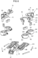
- the first closure parts 2A-2D whose function will be explained in detail below, are arranged on the fastening unit 50 and point, as shown in the exploded view Fig. 3 in conjunction with 6 and 7 can be seen, each with a locking element 23, an adjusting part 21 and an active element 24 rotatably received in a respectively assigned bearing receptacle 502A-502D of the housing part 500.
- each active element 24 On a rotating body 240 of each active element 24 is, for example Fig. 8 can be seen, a toothing 243 is formed, via which each active element 24 is in toothed engagement with an associated toothing section 41A-41D on an adjusting body 40 of the actuating element 4, so that the active elements 24 can be rotated together by actuating the actuating element 4.
- the actuating element 4 is spring-loaded relative to the housing part 500 via a spring element 43, so that the actuating element 4 is actuated in the unlocking direction E against the spring preload of the spring element 43 designed as a tension spring and the actuating element 4 automatically switches to a non-actuated position after an actuation has taken place due to the spring preload Starting position is reset.
- the second closure parts 3A-3D are, for example Figs. 4 and 5 can be seen, in contrast, formed on a horseshoe-shaped base 30 and each have an engagement element 31 with an engagement section 310 formed thereon, which serves to interact with the locking elements 23 of the first closure parts 2A-2D of the fastening unit 50.
- the base 30 is to be fixed to a higher-level unit, for example a vehicle, for example a tank of a motorcycle, via a fastening plate 33 and suitable fastening elements, for example in the form of screws.
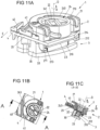
- each closure device 1A-1D will be explained below based on Figs. 9A-9E until Figs. 12A-12E are described, whereby in Figs. 9A-9E until Figs. 12A-12E a single closure device 1 shown in different positions and uniform - representative of the closure devices 1A-1D according to Fig. 1-8 - is designated by the reference number 1.
- the closure device 1 as shown in Figs. 9A-9E until Figs. 12A-12E is shown, has a locking element 23 in the form of a rod-shaped element which is arranged on bearing arms 211, 212 on a body element 210 of the adjusting part 21 and is received with ends spaced apart from one another in bearing openings 213, 214 on the bearing arms 211, 212.
- the adjusting part 21 is adjustable along an actuation direction B, which is opposite to the closing direction Fig. 3 ).
- the adjusting part 21 protrudes through the body 20 with the bearing arms 211, 212 and is coupled to the locking element 23 on a side of the body 20 facing away from the active element 24.
- the active element 24 has a rotating body 240, which is rotatable about an axis of rotation D relative to the body 20.
- the active element 24 is via guide devices 242 in the form of diametrically opposed link guides formed on an external, circumferential surface of the rotating body 240 (see for example Fig. 8 ) with guide elements 215, 216 in the form of guide pins on the inside of the body element 210 of the adjusting part 21 coupled in such a way that a rotational movement of the active element 24 in a direction of rotation A about the axis of rotation D in a linear adjustment movement of the adjusting part 21 in the actuation direction B to the body 20 and thus converted to the bottom 503 of the housing part 500.
- the link guides 242 are extended obliquely to the closing direction
- Figs. 9A-9E show the closure device 1 in the closed position, in which the locking element 23 of the closure part 2 on the fastening unit 50 is lockingly engaged with an engagement element 31 of the closure part 3 on the fastening unit 51, as shown, for example, in the sectional view Fig. 9C in conjunction with the enlarged representation Fig. 13 is visible.
- the locking element 23 is, in addition to the coupling with the adjusting part 21, accommodated in a receiving opening 202 on a support element 200 formed on the body 20 and projecting in the closing direction X from the bottom 503 of the fastening unit 50, as can be seen from a synopsis of Fig. 7 with Fig. 13 is visible.
- the receiving opening 202 is shaped like an elongated hole and extends obliquely to the closing direction X in a plane spanned by the closing direction extends, in which the associated receiving opening 202 is movable.
- the closure parts 2, 3 are placed together along the closure direction
- the engagement element 31 pushes the locking element 23 outwards and thus aside in the receiving openings 202, so that the closure parts 2, 3 are inserted into the inside Figs. 9A-9E reach the closed position shown.
- Each closure part 2, 3 has a magnetic device which is magnetically attracted to one another when the closure parts 2, 3 are placed on one another, so that the attachment of the fastening units 50, 51 on one another is magnetically supported in order to close the closure assembly 5.
- the magnet devices 22, 32 can, for example, each be formed by a permanent magnet, with the magnet devices 22, 32 of the individual closure parts 2, 3 facing each other with opposite poles and thus interacting in a magnetically attractive manner. It is also conceivable to design one of the magnet devices 22, 32 with a permanent magnet and the other magnet device 32, 22 with a magnetic armature made of a ferromagnetic material.
- the magnetic device 22 of the closure part 2 is accommodated in a mounting opening 241 within the rotating body 240 of the active element 24, so that the magnetic device 22 can be rotated together with the active element 24 about the axis of rotation D when the active element 24 is rotated.
- the magnet device 32 of the closure part 3 is, in contrast, accommodated within the base 30.
- the magnet device 32 of the second closure part 3 interacts with the locking element 23 in a magnetically attractive manner. This causes the locking element 23 to engage with the engagement section 310 on the engagement element 31 in the closed position is pulled so that a positive lock is created between the closure parts 2, 3, as shown Figs. 9A-9E is visible.
- the locking element 23 wedges between an inclined surface 311 on the engagement section 310 and an opposite inclined surface 201 within the receiving opening 202 on the support element 200, as shown Fig. 13 is visible.
- the closure parts 2, 3 are thus held together in a locked manner and cannot easily separate from one another, at least not without releasing the lock (although it may be possible for the closure parts 2, 3 to be separated if a predetermined limit force is exceeded).
- the active element 24 can be rotated about the axis of rotation D in the direction of rotation A by moving the actuating element 4 in the unlocking direction E to the housing part 500 of the fastening unit 50.
- the active elements 24 of all closure devices 1A-1D of the closure assembly 5 are actuated together, caused by the gear connection between the actuation element 4 and the individual active elements 24.
- each closure device 1 By rotating the active element 24 in the direction of rotation A, the adjusting part 21 of each closure device 1 becomes like this Figs. 10A-10D and 11A-11D can be seen, adjusted in the actuation direction B. As a result, the locking element 23 is taken along, with the locking element 23 running onto the inclined surface 311 on the engagement section 310 of the engagement element 31, thereby being adjusted outwards in the transverse direction Q and thus being moved past the engagement element 31.
- the magnetic device 22 of the closure part 2 is also rotated, weakens, as shown, for example, in the superimposed, transparent view Fig. 11 As can be seen, the magnetic attraction between the magnetic devices 22, 32 decreases because the magnetic devices 22, 32 are brought out of alignment with one another.
- the closure parts 2, 3 can thus be detached from one another in a simple manner against the closing direction X, as shown in Figs. 12A-12E is shown.
- the force required to open is predetermined by the magnetic force that acts between the magnet device 22 and the magnet device 32.
- the adjustment part 21 is therefore magnetically biased and cannot easily be accidentally opened by small trigger forces.
- Opening the closure device 1 is easy and comfortable.
- a user can simply grab the actuating element 4 on the handle 42 and pull it in the unlocking direction E.
- the closure devices 1A-1D can thereby be opened together, so that the fastening units 50, 51 can be released from one another in the opposite direction to the closing direction X.
- FIG. 14 to 22A-22C Another exemplary embodiment of a closure assembly 5 is shown in Figs. 14 to 22A-22C shown.
- a closure assembly 5 has fastening units 50, 51 which can be attached to one another in order to establish a connection between the fastening units 50, 51 and thus assemblies connected to the fastening units 50, 51.
- a first fastening unit 50 has a housing formed by housing parts 500, 501 which encloses a locking assembly 25.
- the locking assembly 25 forms locking devices 2A-2D, each of which has a locking element 23, which is arranged on associated support elements 200 in the form of tabs protruding from a disk body 250 and is guided in receiving openings 202 in the form of elongated holes on the support elements 200.
- Adjusting parts 21 of the locking devices 2A-2D are formed in the illustrated embodiment by an arrangement of sliding elements 217, which are guided on the housing part 500 of the housing and have bearing openings 213, 214 for acting on ends of the locking elements 23.
- an active element 24 is rotatably mounted about an axis of rotation D, which is assigned to the closure devices 2A-2D and forms guide devices 242 for cooperation with the sliding elements 217.
- the active element 24 is mounted on a bearing element 504 of the housing part 501 and can be rotated in order to adjust the sliding elements 217 together and thereby act on the locking elements 23.
- An actuating element 4 has an adjusting body 40 in the form of an elongated rod, which is coupled to a handle 42 on which a user can grip to actuate the actuating element 40.
- the actuating element 4 is guided displaceably between the housing parts 500, 501 along an unlocking direction E and is coupled to the active element 24 via a coupling element 400 in the form of a coupling pin in such a way that the active element 24 can be rotated about the axis of rotation D by longitudinally displacing the actuating element 4. in order to adjust the sliding elements 217 in this way.
- a second fastening unit 51 is formed by a body 30, on which closure parts 3A-3D are formed, each with an engagement element 31 in the form of an engagement section 310 delimited by a projection.
- a closure part 3A, 3D of the fastening unit 51 is assigned to each closure part 2A-2D of the fastening unit 50.
- Magnetic elements 22 are arranged on the active element 24 in the form of an arrangement of permanent magnets.
- the magnetic elements 22 are assigned to the fastening unit 50.
- Magnetic elements 32 are arranged on the body 30 of the fastening unit 51 in the form of an arrangement of permanent magnets. Through interaction of the magnetic elements 22, 32, the fastening units 50, 51 are attached to produce a locked connection between the closure parts 2A-2D, 3A-3D in a magnetically supported manner.
- Fig. 15 shows the closure assembly 5 in an open position.
- Fig. 16 shows the closure assembly 5 in a closed position. In the closed position, the fastening units 50, 51 are connected to one another and locked together in such a way that the fastening units 50, 51 and thus assemblies that are connected to the fastening units 50, 51 are held together firmly and resiliently.
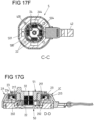
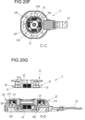
- FIG. 17A to 17G show views of the closure assembly 5 in the closed position.
- the locking elements 23 are in the associated receiving openings 202 of the support elements 200 of the locking assembly 25 in a position that is approximate to the fastening unit 51. Due to the oblique extension of the receiving openings 202, the locking elements 23 are offset radially inwards and are in engagement with the engagement elements 31 of the fastening units 51, as shown Fig. 17D is visible. A lock between the fastening units 50, 51 is thus established via the closure parts 2A-2D, 3A-3D.
- the locking elements 23 are magnetic and are automatically pulled into engagement with the engagement elements 31 by magnetic interaction with the magnetic elements 32 of the fastening unit 51, as shown Fig. 17D is visible.
- the sliding elements 217 are raised relative to the active element 24 in the direction of the fastening unit 51, as shown Fig. 17E is visible.
- the sliding elements 217 are not loaded via the active element 24, which is in a non-actuated rotational position.
- the actuating element 4 is actuated via the handle 42 in the unlocking direction E. Due to the coupling of the actuating element 4 via the coupling element 400 with the active element 24, the active element 24 is rotated about the axis of rotation D, as shown in particular Fig. 18F is visible.
- the active element 24 acts on the sliding elements 217 in that guide devices 242 of the active element 24 act on guide pins 215 on the sliding elements 217 and thereby pull the sliding elements 217 downwards in an actuation direction B, as shown Fig. 18D is visible.
- the locking elements 23 are thereby adjusted downwards and outwards in the associated receiving openings 202 of the locking assembly 25, as can be seen from Fig. 18D and 18G , caused by the coupling of the sliding elements 217 with the locking elements 23 via the position openings 213, 214.
- the magnetic elements 22 are also rotated together with the active element 24, so that the magnetic elements 22 are brought out of their opposite position with the magnetic elements 32, as shown Fig. 18G is visible.
- One Magnetic attraction between the fastening units 50, 51 is thus reduced or eliminated or even reversed into repulsion.
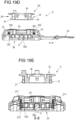
- the fastening units 50, 51 can thus be removed from one another after unlocking via the actuating element 4, as shown in 19A to 19G is shown.
- the actuating element 4 After opening the closure assembly and releasing the handle 42, the actuating element 4 returns to its non-actuated position, shown in 20A to 20G , whereby this resetting of the actuating element 4 occurs automatically, for example by pretensioning a spring element 43 (see Fig. 14 ) he follows.
- the closure assembly 5 is thus in an open position. By reattaching the fastening units 50, 51, the closure assembly 5 can be closed again.
- Figs. 21A-21C and Figs. 22A-22C show separate views of the locking assembly 25 with the closure parts 2A-2D arranged thereon and the active element 24.
- each sliding element 217 which together form the adjustment parts 21 of the closure parts 2A-2D, an inwardly pointing guide pin 215 is formed, which serves to cooperate with the guide devices 242 of the active element 24.
- Each sliding element 217 is assigned a guide device 242 on the outer circumference of the active element 24, so that the sliding elements 217 can be rotated together by rotating the active element 24 about the axis of rotation D.
- the guide devices 242 of the active element 24 in the illustrated embodiment are formed by ramps 246, 247, which delimit a circumferential recess 245 of the active element 24.
- Each sliding element 217 lies with the guide pins 215 in an assigned recess 245 of the active element 24.
- the sliding elements 217 are raised against the actuation direction B to the disk body 250.
- the locking elements 23 are in a raised, inwardly offset position, as can be seen from Fig. 21A .
- the guide pins are in this position 215 on a respective assigned first ramp 246, as shown 21B and 21C is visible.
- the sliding elements 217 are held in the raised position by the ramps 246. Additionally or alternatively, the sliding elements 217 are moved into the raised position with the locking elements 23 and held there. The locking elements 23 move into the upper, inwardly offset locking position on the active element 24 due to magnetic interaction with the magnetic elements 22.
- the active element 24 is rotated to actuate the sliding elements 217, as follows 22A to 22C
- the guide pins 215 of the sliding elements 217 come into contact with the respective assigned ramp 247 on the other side of the assigned recess 245 and run onto this ramp 247.
- the sliding elements 217 are moved together in the actuation direction B and thus adjusted so that the locking elements 23 in the associated receiving openings of the support elements 200 are offset downwards and outwards, as shown Fig. 22A is visible.
- the locking elements 23 are in this way disengaged from the associated engagement elements 31 of the closure parts 3A-3D of the fastening unit 51, as explained above.
- a common active element 24 is provided for jointly unlocking all locking elements 23 of the closure parts 2A-2D.
- the exemplary embodiments are otherwise essentially identical, so that with regard to the functionality of the exemplary embodiment according to Figs. 14 to 22A-22C also refer to the description of the exemplary embodiment Fig. 1 to 13 is referred.
- a closure device of the type described can be used in very different ways.
- a closure assembly can be used to connect an assembly, for example a bag, to a higher-level assembly, for example a vehicle.
- a bag can be attached to a tank of a motorcycle via a closure assembly.
- a closure device of the type described can also be used to connect an electronic device to a higher-level assembly, for example in or on a vehicle, for example a motor vehicle or bicycle.
- a mobile phone can be attached (releasably) to a dashboard of a motor vehicle or to a handlebar of a bicycle using such a device.
- the closure device can also be used to connect other objects to one another, for example as a closure for a helmet, in particular a sports helmet, for a bag or for a piece of clothing.
Landscapes
- Engineering & Computer Science (AREA)
- General Engineering & Computer Science (AREA)
- Mechanical Engineering (AREA)
- Lock And Its Accessories (AREA)
- Slide Fasteners, Snap Fasteners, And Hook Fasteners (AREA)
- Snaps, Bayonet Connections, Set Pins, And Snap Rings (AREA)
- Mutual Connection Of Rods And Tubes (AREA)
- Closures For Containers (AREA)
- Clamps And Clips (AREA)
Claims (15)
- Dispositif de fermeture (1, 1A - 1D), avecune première partie de fermeture (2, 2A - 2D) présentant un corps (20) et une deuxième partie de fermeture (3, 3A - 3D), qui peuvent être placées l'une sur l'autre pour fermer le dispositif de fermeture (1, 1A - 1D) le long d'une direction de fermeture (X) et sont reliées l'une à l'autre dans une position de fermeture, etau moins un élément de verrouillage (23), qui peut être ajusté par rapport au corps (20) de la première partie de fermeture (2, 2A - 2D), etau moins une section de prise (310), qui est formée sur la deuxième partie de fermeture (3, 3A - 3D), dans lequel l'au moins un élément de verrouillage (23) et l'au moins une section de prise (310) sont en prise l'un avec l'autre dans une position de fermeture de telle manière que la première partie de fermeture (2, 2A - 2D) et la deuxième partie de fermeture (3, 3A - 3D) sont verrouillées l'une à l'autre,dans lequel la première partie de fermeture (2, 2A - 2D) présente un premier système magnétique (22) et la deuxième partie de fermeture (3, 3A - 3D) présente un deuxième système magnétique (32), dans lequel le premier système magnétique (22) et le deuxième système magnétique (32) coopèrent de manière à s'attirer l'un l'autre magnétiquement lors du placement de la première partie de fermeture (2, 2A - 2D) et de la deuxième partie de fermeture (3, 3A - 3D) et l'au moins un élément de verrouillage (23) est réalisé de manière magnétique de telle manière que l'au moins un élément de verrouillage (23) est chargé dans la position de fermeture par le premier système magnétique (22) et/ou le deuxième système magnétique (32) en direction d'une prise avec l'au moins une section de prise (310), dans lequel la première partie de fermeture (2, 2A - 2D) présente une partie d'ajustement (21) et un élément actif (24) pouvant tourner autour d'un axe de rotation (D), interagissant avec la partie d'ajustement (21), dans lequel la partie d'ajustement (21) peut être actionnée par torsion de l'élément actif (24) dans une direction d'actionnement (B) pour dégager l'au moins un élément de verrouillage (23) de l'au moins une section de prise (310) pour détacher la première partie de fermeture (2, 2A - 2D) et la deuxième partie de fermeture (3, 3A - 3D) l'une de l'autre,caractérisé en ce quela section de prise (310) présente une première surface oblique (311) s'étendant de manière oblique par rapport à la direction de fermeture (X) et la première partie de fermeture (2, 2A - 2D) présente une deuxième surface oblique (201) s'étendant de manière oblique par rapport à la direction de fermeture (X), dans lequel l'au moins un élément de verrouillage (23) est disposé, dans la position de fermeture, entre la première surface oblique (311) et la deuxième surface oblique (201).
- Dispositif de fermeture (1, 1A - 1D) selon la revendication 1, caractérisé en ce que l'axe de rotation (D) est dirigé le long de la direction de fermeture (X).
- Dispositif de fermeture (1, 1A - 1D) selon la revendication 1 ou 2, caractérisé en ce que la direction d'actionnement (B) est dirigée le long de l'axe de rotation (D).
- Dispositif de fermeture (1, 1A - 1D) selon l'une quelconque des revendications 1 à 3, caractérisé en ce que l'élément actif (24) présente un système de guidage (242), sur lequel la partie d'ajustement (21) est guidée de telle manière que la partie d'ajustement (21) est actionnée lors de la torsion de l'élément actif (24) dans la direction d'actionnement (B).
- Dispositif de fermeture (1, 1A - 1D) selon la revendication 4, caractérisé en ce que le système de guidage (242) est réalisé par un guidage à coulisse ou au moins un plan incliné (246, 247).
- Dispositif de fermeture (1) selon l'une quelconque des revendications précédentes, caractérisé en ce que l'au moins un élément de verrouillage (23) est logé de manière à pouvoir être ajusté dans une ouverture de logement (202) de la première partie de fermeture (2).
- Dispositif de fermeture (1) selon la revendication 6, caractérisé en ce que l'ouverture de logement (202) s'étend de manière oblique par rapport à la direction de fermeture (X) de telle manière que l'au moins un élément de verrouillage (23) peut être ajusté le long d'une direction d'ajustement s'étendant de manière oblique par rapport à la direction de fermeture (X) dans l'ouverture de logement (202).
- Dispositif de fermeture (1, 1A - 1D) selon l'une quelconque des revendications précédentes, caractérisé en ce que l'au moins un élément de verrouillage (23) est disposé sur la partie d'ajustement (21).
- Dispositif de fermeture (1, 1A - 1D) selon la revendication 8, caractérisé en ce que l'au moins un élément de verrouillage (23) est logé dans une ouverture de montage (211, 212) de la partie d'ajustement (21) sur la partie d'ajustement (21) et peut être ajusté de manière transversale par rapport à la direction de fermeture (X) en direction de la partie d'ajustement (21).
- Dispositif de fermeture (1, 1A - 1D) selon l'une quelconque des revendications précédentes, caractérisé en ce que la première surface oblique (311) et la deuxième surface oblique (201) sont disposées dans un plan formé par la direction de fermeture (X) et la direction transversale (Q), de manière parallèle ou selon un angle supérieur à 0 ou inférieur à 0 l'une par rapport à l'autre.
- Dispositif de fermeture (1, 1A - 1D) selon l'une quelconque des revendications précédentes, caractérisé en ce que l'au moins un élément de verrouillage (23) est réalisé en tant qu'élément de barreau étiré en longueur.
- Dispositif de fermeture (1, 1A - 1D) selon l'une quelconque des revendications précédentes, caractérisé en ce que le premier système magnétique (22) est disposé sur l'élément actif (24) et peut être tourné conjointement avec l'élément actif (24).
- Dispositif de fermeture (1, 1A - 1D) selon l'une quelconque des revendications précédentes, caractérisé en ce que lors de la torsion de l'élément actif (24) depuis une position de rotation associée à la position de fermeture, une force d'attraction magnétique entre le premier système magnétique (22) et le deuxième système magnétique (32) est affaiblie.
- Dispositif de fermeture (1, 1A - 1D) selon l'une quelconque des revendications précédentes, caractérisé en ce que la deuxième partie de fermeture (3, 3A - 3D) présente une base (30), sur laquelle est disposée l'au moins une section de prise (310).
- Module de fermeture (5) avec une multitude de dispositifs de fermeture (1, 1A - 1D) selon l'une quelconque des revendications précédentes.
Applications Claiming Priority (2)
| Application Number | Priority Date | Filing Date | Title |
|---|---|---|---|
| DE102019215277.5A DE102019215277A1 (de) | 2019-10-02 | 2019-10-02 | Verschlussvorrichtung mit aneinander ansetzbaren Verschlussteilen |
| PCT/EP2020/077328 WO2021064002A1 (fr) | 2019-10-02 | 2020-09-30 | Appareil de fixation comprenant des pièces de fixation pouvant être placées l'une contre l'autre |
Publications (2)
| Publication Number | Publication Date |
|---|---|
| EP3827178A1 EP3827178A1 (fr) | 2021-06-02 |
| EP3827178B1 true EP3827178B1 (fr) | 2024-02-28 |
Family
ID=72744552
Family Applications (2)
| Application Number | Title | Priority Date | Filing Date |
|---|---|---|---|
| EP20199214.6A Active EP3800360B1 (fr) | 2019-10-02 | 2020-09-30 | Dispositif de verrouillage avec des parts de verrouillage qui s'attachent |
| EP20792926.6A Active EP3827178B1 (fr) | 2019-10-02 | 2020-09-30 | Appareil de fixation comprenant des pièces de fixation pouvant être placées l'une contre l'autre |
Family Applications Before (1)
| Application Number | Title | Priority Date | Filing Date |
|---|---|---|---|
| EP20199214.6A Active EP3800360B1 (fr) | 2019-10-02 | 2020-09-30 | Dispositif de verrouillage avec des parts de verrouillage qui s'attachent |
Country Status (8)
| Country | Link |
|---|---|
| US (1) | US11889901B2 (fr) |
| EP (2) | EP3800360B1 (fr) |
| JP (1) | JP7550749B2 (fr) |
| CN (1) | CN113056216B (fr) |
| DE (1) | DE102019215277A1 (fr) |
| ES (1) | ES2977316T3 (fr) |
| TW (1) | TWI766385B (fr) |
| WO (1) | WO2021064002A1 (fr) |
Families Citing this family (4)
| Publication number | Priority date | Publication date | Assignee | Title |
|---|---|---|---|---|
| DE102020207310B4 (de) * | 2020-06-11 | 2021-12-30 | Fidlock Gmbh | Bei Belastung gesicherte Verschlussvorrichtung |
| DE102022104735B3 (de) * | 2022-02-28 | 2023-06-07 | Fidlock Gmbh | Verschlussvorrichtung zum Verbinden zweier Baugruppen |
| DE102022104734B3 (de) * | 2022-02-28 | 2023-06-01 | Fidlock Gmbh | Verschlussvorrichtung zum Verbinden zweier Baugruppen |
| DE102022104733B3 (de) * | 2022-02-28 | 2023-04-20 | Fidlock Gmbh | Verschlussvorrichtung zum Verbinden zweier Baugruppen |
Family Cites Families (17)
| Publication number | Priority date | Publication date | Assignee | Title |
|---|---|---|---|---|
| DE2656511C2 (de) | 1976-12-14 | 1985-08-29 | Naamloze Vennootschap Nederlandsche Apparatenfabriek Nedap, Groenlo | Befestigungsvorrichtung |
| US6000306A (en) | 1998-06-12 | 1999-12-14 | Kennametal Inc. | Side activated tool unit clamping apparatus using mechanical advantage |
| JP2944643B1 (ja) | 1998-07-09 | 1999-09-06 | 有限会社ターモ | 磁気止め具 |
| US6182336B1 (en) | 1999-02-18 | 2001-02-06 | Irving Bauer | Magnetic safety snap locking device and method of fastening the device with manual resetting |
| US6295702B1 (en) * | 2000-09-15 | 2001-10-02 | Irving Bauer | Locking magnetic fastener |
| DE102004015873B4 (de) * | 2004-03-31 | 2007-03-22 | Joachim Fiedler | Lösbare Magnethalterung |
| PL2436280T3 (pl) * | 2006-07-12 | 2017-12-29 | Fidlock Gmbh | Mechaniczno-magnetyczna konstrukcja łącząca |
| ATE536113T1 (de) * | 2007-07-12 | 2011-12-15 | Fidlock Gmbh | Magnetverschluss mit öffnungsunterstützungsfeder |
| DE102007058188A1 (de) * | 2007-12-04 | 2009-06-10 | Fidlock Gmbh | Magnetische Kopplungsvorrichtung |
| US8353544B2 (en) * | 2008-01-27 | 2013-01-15 | Fidlock Gmbh | Locking magnet closure |
| DE202010010300U1 (de) * | 2009-08-24 | 2010-10-21 | Fidlock Gmbh | Mechanischer Verschluss mit einer Verriegelungsvorrichtung |
| DE102010044144B3 (de) * | 2010-11-18 | 2012-05-31 | Fidlock Gmbh | Verschlussvorrichtung |
| US9869423B2 (en) * | 2013-03-15 | 2018-01-16 | Otter Products, Llc | Releasable mount apparatus and system with lock switch |
| DE102016216422A1 (de) * | 2016-08-31 | 2018-03-01 | Fidlock Gmbh | Verschlussvorrichtung zum Verbinden eines Behälters z.B. an einem Fahrrad |
| WO2018073064A1 (fr) | 2016-10-19 | 2018-04-26 | Axel Tietz | Serrure par insertion magnétique, clé à insertion magnétique et combinaisons de celles-ci |
| DE102017212151A1 (de) * | 2017-07-14 | 2019-01-17 | Fidlock Gmbh | Verschlussvorrichtung mit elektrischen Kontakten |
| DE102018201021A1 (de) | 2017-11-14 | 2019-05-16 | Fidlock Gmbh | Verschlussvorrichtung mit einem Wickelelement |
-
2019
- 2019-10-02 DE DE102019215277.5A patent/DE102019215277A1/de not_active Withdrawn
-
2020
- 2020-09-30 CN CN202080006254.8A patent/CN113056216B/zh active Active
- 2020-09-30 TW TW109134269A patent/TWI766385B/zh active
- 2020-09-30 EP EP20199214.6A patent/EP3800360B1/fr active Active
- 2020-09-30 ES ES20792926T patent/ES2977316T3/es active Active
- 2020-09-30 EP EP20792926.6A patent/EP3827178B1/fr active Active
- 2020-09-30 US US17/277,336 patent/US11889901B2/en active Active
- 2020-09-30 WO PCT/EP2020/077328 patent/WO2021064002A1/fr not_active Ceased
- 2020-09-30 JP JP2021518758A patent/JP7550749B2/ja active Active
Also Published As
| Publication number | Publication date |
|---|---|
| TW202129160A (zh) | 2021-08-01 |
| ES2977316T3 (es) | 2024-08-21 |
| US20220312904A1 (en) | 2022-10-06 |
| TWI766385B (zh) | 2022-06-01 |
| EP3800360A1 (fr) | 2021-04-07 |
| CN113056216A (zh) | 2021-06-29 |
| WO2021064002A1 (fr) | 2021-04-08 |
| US11889901B2 (en) | 2024-02-06 |
| CN113056216B (zh) | 2024-09-06 |
| JP2022550493A (ja) | 2022-12-02 |
| EP3800360B1 (fr) | 2023-03-01 |
| DE102019215277A1 (de) | 2021-04-08 |
| JP7550749B2 (ja) | 2024-09-13 |
| EP3827178A1 (fr) | 2021-06-02 |
Similar Documents
| Publication | Publication Date | Title |
|---|---|---|
| EP3827178B1 (fr) | Appareil de fixation comprenant des pièces de fixation pouvant être placées l'une contre l'autre | |
| EP4023095B1 (fr) | Dispositif de verrouillage pourvu de pièces de verrouillage pouvant être placées les unes contre les autres | |
| EP3857075B1 (fr) | Dispositif de fermeture à éléments de fermeture pouvant être appliqués l'un contre l'autre | |
| EP2389084B1 (fr) | Dispositif de fermeture destiné à relier deux pièces | |
| EP3943762B1 (fr) | Dispositif de liaison permettant de relier de manière amovible deux modules | |
| EP3791075B1 (fr) | Dispositif de fermeture servant à relier deux modules l'un à l'autre | |
| EP4368059B1 (fr) | Dispositif de fermeture comprenant deux parties de fermeture pouvant être reliées à un module de logement | |
| DE102022207115B3 (de) | Verschlussvorrichtung | |
| EP1574641B1 (fr) | Dispositif de fermeture pour conteneurs, portes, armoires, meubles ou similaires | |
| WO2024133433A1 (fr) | Dispositif de fermeture doté d'un élément de liaison réglable | |
| EP4487018A1 (fr) | Dispositif de fermeture pour relier deux ensembles | |
| EP4493018B1 (fr) | Fermoir | |
| DE102023127479B3 (de) | Verschlussvorrichtung zum Verbinden zweier Gegenstände | |
| DE102022104735B3 (de) | Verschlussvorrichtung zum Verbinden zweier Baugruppen | |
| DE102022203588A1 (de) | Verschlussvorrichtung | |
| DE4019702A1 (de) | Loesbare arretiervorrichtung | |
| DE202019005390U1 (de) | Verschlussvorrichtung zum Verbinden von zwei Baugruppen miteinander |
Legal Events
| Date | Code | Title | Description |
|---|---|---|---|
| STAA | Information on the status of an ep patent application or granted ep patent |
Free format text: STATUS: UNKNOWN |
|
| STAA | Information on the status of an ep patent application or granted ep patent |
Free format text: STATUS: THE INTERNATIONAL PUBLICATION HAS BEEN MADE |
|
| PUAI | Public reference made under article 153(3) epc to a published international application that has entered the european phase |
Free format text: ORIGINAL CODE: 0009012 |
|
| STAA | Information on the status of an ep patent application or granted ep patent |
Free format text: STATUS: REQUEST FOR EXAMINATION WAS MADE |
|
| 17P | Request for examination filed |
Effective date: 20210224 |
|
| AK | Designated contracting states |
Kind code of ref document: A1 Designated state(s): AL AT BE BG CH CY CZ DE DK EE ES FI FR GB GR HR HU IE IS IT LI LT LU LV MC MK MT NL NO PL PT RO RS SE SI SK SM TR |
|
| REG | Reference to a national code |
Ref country code: HK Ref legal event code: DE Ref document number: 40047616 Country of ref document: HK |
|
| DAV | Request for validation of the european patent (deleted) | ||
| DAX | Request for extension of the european patent (deleted) | ||
| GRAP | Despatch of communication of intention to grant a patent |
Free format text: ORIGINAL CODE: EPIDOSNIGR1 |
|
| STAA | Information on the status of an ep patent application or granted ep patent |
Free format text: STATUS: GRANT OF PATENT IS INTENDED |
|
| INTG | Intention to grant announced |
Effective date: 20230515 |
|
| GRAJ | Information related to disapproval of communication of intention to grant by the applicant or resumption of examination proceedings by the epo deleted |
Free format text: ORIGINAL CODE: EPIDOSDIGR1 |
|
| STAA | Information on the status of an ep patent application or granted ep patent |
Free format text: STATUS: REQUEST FOR EXAMINATION WAS MADE |
|
| P01 | Opt-out of the competence of the unified patent court (upc) registered |
Effective date: 20230821 |
|
| INTC | Intention to grant announced (deleted) | ||
| GRAP | Despatch of communication of intention to grant a patent |
Free format text: ORIGINAL CODE: EPIDOSNIGR1 |
|
| STAA | Information on the status of an ep patent application or granted ep patent |
Free format text: STATUS: GRANT OF PATENT IS INTENDED |
|
| INTG | Intention to grant announced |
Effective date: 20231205 |
|
| GRAS | Grant fee paid |
Free format text: ORIGINAL CODE: EPIDOSNIGR3 |
|
| GRAA | (expected) grant |
Free format text: ORIGINAL CODE: 0009210 |
|
| STAA | Information on the status of an ep patent application or granted ep patent |
Free format text: STATUS: THE PATENT HAS BEEN GRANTED |
|
| AK | Designated contracting states |
Kind code of ref document: B1 Designated state(s): AL AT BE BG CH CY CZ DE DK EE ES FI FR GB GR HR HU IE IS IT LI LT LU LV MC MK MT NL NO PL PT RO RS SE SI SK SM TR |
|
| REG | Reference to a national code |
Ref country code: GB Ref legal event code: FG4D Free format text: NOT ENGLISH |
|
| REG | Reference to a national code |
Ref country code: CH Ref legal event code: EP |
|
| REG | Reference to a national code |
Ref country code: DE Ref legal event code: R096 Ref document number: 502020007192 Country of ref document: DE |
|
| REG | Reference to a national code |
Ref country code: IE Ref legal event code: FG4D Free format text: LANGUAGE OF EP DOCUMENT: GERMAN |
|
| REG | Reference to a national code |
Ref country code: LT Ref legal event code: MG9D |
|
| PG25 | Lapsed in a contracting state [announced via postgrant information from national office to epo] |
Ref country code: IS Free format text: LAPSE BECAUSE OF FAILURE TO SUBMIT A TRANSLATION OF THE DESCRIPTION OR TO PAY THE FEE WITHIN THE PRESCRIBED TIME-LIMIT Effective date: 20240628 |
|
| REG | Reference to a national code |
Ref country code: NL Ref legal event code: MP Effective date: 20240228 |
|
| PG25 | Lapsed in a contracting state [announced via postgrant information from national office to epo] |
Ref country code: LT Free format text: LAPSE BECAUSE OF FAILURE TO SUBMIT A TRANSLATION OF THE DESCRIPTION OR TO PAY THE FEE WITHIN THE PRESCRIBED TIME-LIMIT Effective date: 20240228 |
|
| PG25 | Lapsed in a contracting state [announced via postgrant information from national office to epo] |
Ref country code: GR Free format text: LAPSE BECAUSE OF FAILURE TO SUBMIT A TRANSLATION OF THE DESCRIPTION OR TO PAY THE FEE WITHIN THE PRESCRIBED TIME-LIMIT Effective date: 20240529 |
|
| PG25 | Lapsed in a contracting state [announced via postgrant information from national office to epo] |
Ref country code: HR Free format text: LAPSE BECAUSE OF FAILURE TO SUBMIT A TRANSLATION OF THE DESCRIPTION OR TO PAY THE FEE WITHIN THE PRESCRIBED TIME-LIMIT Effective date: 20240228 Ref country code: RS Free format text: LAPSE BECAUSE OF FAILURE TO SUBMIT A TRANSLATION OF THE DESCRIPTION OR TO PAY THE FEE WITHIN THE PRESCRIBED TIME-LIMIT Effective date: 20240528 Ref country code: NL Free format text: LAPSE BECAUSE OF FAILURE TO SUBMIT A TRANSLATION OF THE DESCRIPTION OR TO PAY THE FEE WITHIN THE PRESCRIBED TIME-LIMIT Effective date: 20240228 |
|
| PG25 | Lapsed in a contracting state [announced via postgrant information from national office to epo] |
Ref country code: RS Free format text: LAPSE BECAUSE OF FAILURE TO SUBMIT A TRANSLATION OF THE DESCRIPTION OR TO PAY THE FEE WITHIN THE PRESCRIBED TIME-LIMIT Effective date: 20240528 Ref country code: NO Free format text: LAPSE BECAUSE OF FAILURE TO SUBMIT A TRANSLATION OF THE DESCRIPTION OR TO PAY THE FEE WITHIN THE PRESCRIBED TIME-LIMIT Effective date: 20240528 Ref country code: NL Free format text: LAPSE BECAUSE OF FAILURE TO SUBMIT A TRANSLATION OF THE DESCRIPTION OR TO PAY THE FEE WITHIN THE PRESCRIBED TIME-LIMIT Effective date: 20240228 Ref country code: LT Free format text: LAPSE BECAUSE OF FAILURE TO SUBMIT A TRANSLATION OF THE DESCRIPTION OR TO PAY THE FEE WITHIN THE PRESCRIBED TIME-LIMIT Effective date: 20240228 Ref country code: IS Free format text: LAPSE BECAUSE OF FAILURE TO SUBMIT A TRANSLATION OF THE DESCRIPTION OR TO PAY THE FEE WITHIN THE PRESCRIBED TIME-LIMIT Effective date: 20240628 Ref country code: HR Free format text: LAPSE BECAUSE OF FAILURE TO SUBMIT A TRANSLATION OF THE DESCRIPTION OR TO PAY THE FEE WITHIN THE PRESCRIBED TIME-LIMIT Effective date: 20240228 Ref country code: GR Free format text: LAPSE BECAUSE OF FAILURE TO SUBMIT A TRANSLATION OF THE DESCRIPTION OR TO PAY THE FEE WITHIN THE PRESCRIBED TIME-LIMIT Effective date: 20240529 Ref country code: FI Free format text: LAPSE BECAUSE OF FAILURE TO SUBMIT A TRANSLATION OF THE DESCRIPTION OR TO PAY THE FEE WITHIN THE PRESCRIBED TIME-LIMIT Effective date: 20240228 Ref country code: BG Free format text: LAPSE BECAUSE OF FAILURE TO SUBMIT A TRANSLATION OF THE DESCRIPTION OR TO PAY THE FEE WITHIN THE PRESCRIBED TIME-LIMIT Effective date: 20240228 |
|
| PG25 | Lapsed in a contracting state [announced via postgrant information from national office to epo] |
Ref country code: PL Free format text: LAPSE BECAUSE OF FAILURE TO SUBMIT A TRANSLATION OF THE DESCRIPTION OR TO PAY THE FEE WITHIN THE PRESCRIBED TIME-LIMIT Effective date: 20240228 Ref country code: PT Free format text: LAPSE BECAUSE OF FAILURE TO SUBMIT A TRANSLATION OF THE DESCRIPTION OR TO PAY THE FEE WITHIN THE PRESCRIBED TIME-LIMIT Effective date: 20240628 |
|
| REG | Reference to a national code |
Ref country code: ES Ref legal event code: FG2A Ref document number: 2977316 Country of ref document: ES Kind code of ref document: T3 Effective date: 20240821 |
|
| PG25 | Lapsed in a contracting state [announced via postgrant information from national office to epo] |
Ref country code: SE Free format text: LAPSE BECAUSE OF FAILURE TO SUBMIT A TRANSLATION OF THE DESCRIPTION OR TO PAY THE FEE WITHIN THE PRESCRIBED TIME-LIMIT Effective date: 20240228 Ref country code: PT Free format text: LAPSE BECAUSE OF FAILURE TO SUBMIT A TRANSLATION OF THE DESCRIPTION OR TO PAY THE FEE WITHIN THE PRESCRIBED TIME-LIMIT Effective date: 20240628 Ref country code: PL Free format text: LAPSE BECAUSE OF FAILURE TO SUBMIT A TRANSLATION OF THE DESCRIPTION OR TO PAY THE FEE WITHIN THE PRESCRIBED TIME-LIMIT Effective date: 20240228 Ref country code: LV Free format text: LAPSE BECAUSE OF FAILURE TO SUBMIT A TRANSLATION OF THE DESCRIPTION OR TO PAY THE FEE WITHIN THE PRESCRIBED TIME-LIMIT Effective date: 20240228 |
|
| PG25 | Lapsed in a contracting state [announced via postgrant information from national office to epo] |
Ref country code: DK Free format text: LAPSE BECAUSE OF FAILURE TO SUBMIT A TRANSLATION OF THE DESCRIPTION OR TO PAY THE FEE WITHIN THE PRESCRIBED TIME-LIMIT Effective date: 20240228 |
|
| PG25 | Lapsed in a contracting state [announced via postgrant information from national office to epo] |
Ref country code: SM Free format text: LAPSE BECAUSE OF FAILURE TO SUBMIT A TRANSLATION OF THE DESCRIPTION OR TO PAY THE FEE WITHIN THE PRESCRIBED TIME-LIMIT Effective date: 20240228 |
|
| PG25 | Lapsed in a contracting state [announced via postgrant information from national office to epo] |
Ref country code: CZ Free format text: LAPSE BECAUSE OF FAILURE TO SUBMIT A TRANSLATION OF THE DESCRIPTION OR TO PAY THE FEE WITHIN THE PRESCRIBED TIME-LIMIT Effective date: 20240228 Ref country code: EE Free format text: LAPSE BECAUSE OF FAILURE TO SUBMIT A TRANSLATION OF THE DESCRIPTION OR TO PAY THE FEE WITHIN THE PRESCRIBED TIME-LIMIT Effective date: 20240228 |
|
| PG25 | Lapsed in a contracting state [announced via postgrant information from national office to epo] |
Ref country code: SK Free format text: LAPSE BECAUSE OF FAILURE TO SUBMIT A TRANSLATION OF THE DESCRIPTION OR TO PAY THE FEE WITHIN THE PRESCRIBED TIME-LIMIT Effective date: 20240228 |
|
| PG25 | Lapsed in a contracting state [announced via postgrant information from national office to epo] |
Ref country code: SM Free format text: LAPSE BECAUSE OF FAILURE TO SUBMIT A TRANSLATION OF THE DESCRIPTION OR TO PAY THE FEE WITHIN THE PRESCRIBED TIME-LIMIT Effective date: 20240228 Ref country code: SK Free format text: LAPSE BECAUSE OF FAILURE TO SUBMIT A TRANSLATION OF THE DESCRIPTION OR TO PAY THE FEE WITHIN THE PRESCRIBED TIME-LIMIT Effective date: 20240228 Ref country code: RO Free format text: LAPSE BECAUSE OF FAILURE TO SUBMIT A TRANSLATION OF THE DESCRIPTION OR TO PAY THE FEE WITHIN THE PRESCRIBED TIME-LIMIT Effective date: 20240228 Ref country code: EE Free format text: LAPSE BECAUSE OF FAILURE TO SUBMIT A TRANSLATION OF THE DESCRIPTION OR TO PAY THE FEE WITHIN THE PRESCRIBED TIME-LIMIT Effective date: 20240228 Ref country code: DK Free format text: LAPSE BECAUSE OF FAILURE TO SUBMIT A TRANSLATION OF THE DESCRIPTION OR TO PAY THE FEE WITHIN THE PRESCRIBED TIME-LIMIT Effective date: 20240228 Ref country code: CZ Free format text: LAPSE BECAUSE OF FAILURE TO SUBMIT A TRANSLATION OF THE DESCRIPTION OR TO PAY THE FEE WITHIN THE PRESCRIBED TIME-LIMIT Effective date: 20240228 |
|
| REG | Reference to a national code |
Ref country code: DE Ref legal event code: R097 Ref document number: 502020007192 Country of ref document: DE |
|
| PLBE | No opposition filed within time limit |
Free format text: ORIGINAL CODE: 0009261 |
|
| STAA | Information on the status of an ep patent application or granted ep patent |
Free format text: STATUS: NO OPPOSITION FILED WITHIN TIME LIMIT |
|
| 26N | No opposition filed |
Effective date: 20241129 |
|
| PG25 | Lapsed in a contracting state [announced via postgrant information from national office to epo] |
Ref country code: SI Free format text: LAPSE BECAUSE OF FAILURE TO SUBMIT A TRANSLATION OF THE DESCRIPTION OR TO PAY THE FEE WITHIN THE PRESCRIBED TIME-LIMIT Effective date: 20240228 Ref country code: MC Free format text: LAPSE BECAUSE OF FAILURE TO SUBMIT A TRANSLATION OF THE DESCRIPTION OR TO PAY THE FEE WITHIN THE PRESCRIBED TIME-LIMIT Effective date: 20240228 |
|
| REG | Reference to a national code |
Ref country code: CH Ref legal event code: PL |
|
| PG25 | Lapsed in a contracting state [announced via postgrant information from national office to epo] |
Ref country code: LU Free format text: LAPSE BECAUSE OF NON-PAYMENT OF DUE FEES Effective date: 20240930 |
|
| REG | Reference to a national code |
Ref country code: BE Ref legal event code: MM Effective date: 20240930 |
|
| PG25 | Lapsed in a contracting state [announced via postgrant information from national office to epo] |
Ref country code: BE Free format text: LAPSE BECAUSE OF NON-PAYMENT OF DUE FEES Effective date: 20240930 |
|
| PG25 | Lapsed in a contracting state [announced via postgrant information from national office to epo] |
Ref country code: CH Free format text: LAPSE BECAUSE OF NON-PAYMENT OF DUE FEES Effective date: 20240930 |
|
| PG25 | Lapsed in a contracting state [announced via postgrant information from national office to epo] |
Ref country code: IE Free format text: LAPSE BECAUSE OF NON-PAYMENT OF DUE FEES Effective date: 20240930 |
|
| PGFP | Annual fee paid to national office [announced via postgrant information from national office to epo] |
Ref country code: DE Payment date: 20250919 Year of fee payment: 6 |
|
| PGFP | Annual fee paid to national office [announced via postgrant information from national office to epo] |
Ref country code: GB Payment date: 20250923 Year of fee payment: 6 |
|
| PGFP | Annual fee paid to national office [announced via postgrant information from national office to epo] |
Ref country code: FR Payment date: 20250924 Year of fee payment: 6 Ref country code: AT Payment date: 20251020 Year of fee payment: 5 |
|
| PGFP | Annual fee paid to national office [announced via postgrant information from national office to epo] |
Ref country code: IT Payment date: 20250930 Year of fee payment: 6 |
|
| PG25 | Lapsed in a contracting state [announced via postgrant information from national office to epo] |
Ref country code: CY Free format text: LAPSE BECAUSE OF FAILURE TO SUBMIT A TRANSLATION OF THE DESCRIPTION OR TO PAY THE FEE WITHIN THE PRESCRIBED TIME-LIMIT; INVALID AB INITIO Effective date: 20200930 |
|
| PGFP | Annual fee paid to national office [announced via postgrant information from national office to epo] |
Ref country code: ES Payment date: 20251020 Year of fee payment: 6 |
|
| PG25 | Lapsed in a contracting state [announced via postgrant information from national office to epo] |
Ref country code: HU Free format text: LAPSE BECAUSE OF FAILURE TO SUBMIT A TRANSLATION OF THE DESCRIPTION OR TO PAY THE FEE WITHIN THE PRESCRIBED TIME-LIMIT; INVALID AB INITIO Effective date: 20200930 |